EP2840204A2 - Lock cylinder - Google Patents
Lock cylinder Download PDFInfo
- Publication number
- EP2840204A2 EP2840204A2 EP14182009.2A EP14182009A EP2840204A2 EP 2840204 A2 EP2840204 A2 EP 2840204A2 EP 14182009 A EP14182009 A EP 14182009A EP 2840204 A2 EP2840204 A2 EP 2840204A2
- Authority
- EP
- European Patent Office
- Prior art keywords
- driver
- sleeper
- lock cylinder
- hub
- housing
- Prior art date
- Legal status (The legal status is an assumption and is not a legal conclusion. Google has not performed a legal analysis and makes no representation as to the accuracy of the status listed.)
- Granted
Links
- 241001669679 Eleotris Species 0.000 claims abstract description 66
- 230000004913 activation Effects 0.000 claims description 9
- 238000006073 displacement reaction Methods 0.000 claims description 7
- 230000000717 retained effect Effects 0.000 claims description 2
- 230000008878 coupling Effects 0.000 description 67
- 238000010168 coupling process Methods 0.000 description 67
- 238000005859 coupling reaction Methods 0.000 description 67
- 210000003746 feather Anatomy 0.000 description 7
- 238000000034 method Methods 0.000 description 4
- 240000006829 Ficus sundaica Species 0.000 description 3
- 230000000903 blocking effect Effects 0.000 description 2
- 238000005553 drilling Methods 0.000 description 2
- 238000004519 manufacturing process Methods 0.000 description 2
- 241001391944 Commicarpus scandens Species 0.000 description 1
- 238000005452 bending Methods 0.000 description 1
- 230000000295 complement effect Effects 0.000 description 1
- 230000012447 hatching Effects 0.000 description 1
- 230000002427 irreversible effect Effects 0.000 description 1
- 230000001846 repelling effect Effects 0.000 description 1
- 238000000926 separation method Methods 0.000 description 1
- 238000010008 shearing Methods 0.000 description 1
- 239000007787 solid Substances 0.000 description 1
- 230000001960 triggered effect Effects 0.000 description 1
Images


Classifications
-
- E—FIXED CONSTRUCTIONS
- E05—LOCKS; KEYS; WINDOW OR DOOR FITTINGS; SAFES
- E05B—LOCKS; ACCESSORIES THEREFOR; HANDCUFFS
- E05B17/00—Accessories in connection with locks
- E05B17/0054—Fraction or shear lines; Slip-clutches, resilient parts or the like for preventing damage when forced or slammed
- E05B17/0062—Fraction or shear lines; Slip-clutches, resilient parts or the like for preventing damage when forced or slammed with destructive disengagement
-
- E—FIXED CONSTRUCTIONS
- E05—LOCKS; KEYS; WINDOW OR DOOR FITTINGS; SAFES
- E05B—LOCKS; ACCESSORIES THEREFOR; HANDCUFFS
- E05B17/00—Accessories in connection with locks
- E05B17/20—Means independent of the locking mechanism for preventing unauthorised opening, e.g. for securing the bolt in the fastening position
- E05B17/2084—Means to prevent forced opening by attack, tampering or jimmying
- E05B17/2092—Means responsive to tampering or attack providing additional locking
-
- E—FIXED CONSTRUCTIONS
- E05—LOCKS; KEYS; WINDOW OR DOOR FITTINGS; SAFES
- E05B—LOCKS; ACCESSORIES THEREFOR; HANDCUFFS
- E05B9/00—Lock casings or latch-mechanism casings ; Fastening locks or fasteners or parts thereof to the wing
- E05B9/04—Casings of cylinder locks
- E05B9/041—Double cylinder locks
-
- E—FIXED CONSTRUCTIONS
- E05—LOCKS; KEYS; WINDOW OR DOOR FITTINGS; SAFES
- E05B—LOCKS; ACCESSORIES THEREFOR; HANDCUFFS
- E05B9/00—Lock casings or latch-mechanism casings ; Fastening locks or fasteners or parts thereof to the wing
- E05B9/10—Coupling devices for the two halves of double cylinder locks, e.g. devices for coupling the rotor with the locking cam
-
- E—FIXED CONSTRUCTIONS
- E05—LOCKS; KEYS; WINDOW OR DOOR FITTINGS; SAFES
- E05B—LOCKS; ACCESSORIES THEREFOR; HANDCUFFS
- E05B9/00—Lock casings or latch-mechanism casings ; Fastening locks or fasteners or parts thereof to the wing
- E05B9/04—Casings of cylinder locks
- E05B2009/046—Cylinder locks operated by knobs or handles
Definitions
- the present invention relates to a lock cylinder with a housing, a rotatable driver in the housing with locking lug and with an outside and inside on both sides of the driver, wherein at least on the outside of a cylinder core is provided with tumblers and on the inside of a biased by spring force sleepers which is locked by an axially displaceable by spring force part and at least partially retained in the housing and blocks the lock cylinder when the outer side breaks away due to omission of the lock.
- Another method is to break out the entire outer part of the lock cylinder.
- the housing of the lock cylinder is greatly weakened in the middle;
- breaking points are sometimes provided, so that the outer part only partially breaks away and thus the driver and the locking lug are not directly accessible.
- the clutch is usually moved by the key; when a key is inserted inside, it is moved towards the outside of the lock cylinder and thereby couples the inner cylinder core with the locking lug. Often the coupling is biased by a spring in one direction, so that - if no key is plugged - occupies a defined position.
- the clutch can assume a third position when the outer cylinder core or the entire outer lock cylinder half is forcibly removed.
- the clutch is then moved by a spring even further towards the outside of the lock cylinder and blocked in this position by a sleeper.
- the inner cylinder is constantly rotatably connected to the locking lug, and the locking lug can only be rotated when a matching key is inserted on the inside.
- this solution is only a small advantage over conventional lock cylinders, where the coupling is biased towards the outside. With the latter locks you can simply push back the clutch and then move the locking lug; in the lock cylinder according to the WO 2009/156731 A If this is not so easy because of the sleeper, but if you hit the clutch with force, the sleeper is sheared off (analogous to the tumblers when "pulling" the cylinder core) and the clutch can be disengaged. Thereafter, the locking nose is movable again.
- a lock cylinder of the type mentioned is from the EP 2466039 A known.
- a double lock cylinder is described with sleepers, which are activated when canceling the outer part and should prevent rotation of the driver with the locking lug.
- the driver is arranged axially displaceable against spring force.
- This double lock cylinder will break in force application for lack of a defined breaking point at the threaded hole for the mounting bolt in Einstemmisch so that the driver can be broken out.
- EP 2466039 A lies in the displacement of the driver. The idea is understandable, as long as the double cylinder is not installed in a one-punch lock. As a result of the standard tolerances between the locking lug and the housing bottom or the ceiling of the Einstemmisches the locking lug hardly move axially in the Einstemmzzi. However, since the locking lug is formed integrally with the driver, the Einstemm240 impeded the safe operation and possibly prevents the engagement of the sleeper.
- Another disadvantage of this double-lock cylinder is that the sleeper is not activated when pulling the outer cylinder core, it must be broken off the entire outer part of the double lock cylinder, so that the sleeper is activated.
- a lock cylinder of the type mentioned according to the invention that in the housing on the outside between the immovable in the axial direction driver and the nearest tumbler a predetermined breaking point is provided and that the axially displaceable part relative to the driver slidably and constantly rotatably mounted in this is spring-loaded in the axial direction on the front side of the cylinder core of the outside directly or indirectly.
- the sleeper is provided in the coupling part, and he engages - when it is activated - in an opening in the driver.
- the sleeper according to the invention is not provided in the region of the driver or the closing nose, but further inside, so that it is less accessible from the outside. There is also more space available.
- the main advantage is that not the clutch (which can be disengaged by moving) is blocked, but a part that is permanently connected to the driver rotation. Characterized in that the blocking according to the invention acts on a part which is permanently connected in rotation with the driver, a repelling of this part in the starting position is ineffective.
- this part may be the hub, which is often present anyway, in a rotary knob cylinder, this may be the shaft of the knob, or of course also a hub.
- the driver together with the locking nose axially immovable, and it is located in the interior of an axially displaceable (but constantly rotatably connected to the driver) part, which bears against the cylinder core of the outside.
- an axially displaceable (but constantly rotatably connected to the driver) part which bears against the cylinder core of the outside.
- the axial displaceability of the constantly rotatably connected to the driver part is at most as large as the diameter of the sleeper, preferably at most half as large. In this way, a shearing of the sleeper is impossible. Since according to the invention the sleeper does not act on the coupling (which inevitably requires a larger displacement), the axial displaceability of the part to be blocked can be optimized for the present purpose; Normally, this part never moves axially, but only when a violent attempt at break-up takes place. Slightly less than half the sleeper's diameter is currently considered optimal; then the sleeper can be bent at most, but never sheared off.
- the part permanently connected to the driver is non-rotatably a hub of the driver and guided on both sides of the carrier in the housing. Since the lock cylinder does not break exactly in the middle as a result of the predetermined breaking point, but just before the driver, this results in a good guidance of the driver even after the break, which makes a violent "tipping out” of the locking lug from the plane in which it normally rotates, difficult.
- the lock cylinder is designed as a double lock cylinder, it is expedient if the sleeper - when breaking away the outside or pulling the outer cylinder core - the cylinder core of the inside with the permanently rotatably connected to the driver part couples. In this way, the lock cylinder can be locked from the inside even when the sleeper was active, so that an emergency opening is guaranteed after a break-in attempt. However, as long as no key is attached to the inside, the driver is blocked.
- the cylinder core of the inside is extended sleeve-shaped in the direction of the driver, that in the region of this sleeve-shaped extension, the hub is axially displaceable, that for the sleeper in the region of this sleeve-shaped extension a housing bore is provided which continues in the sleeve-shaped extension and in the hub - after axial displacement of the same - in a blind hole, and that the sleeper is in two parts, wherein the hub-facing part has a height corresponding to the thickness of the sleeve-shaped extension.
- the hub facing away from the part of the sleeper is formed on the side facing the hub cone-shaped. Due to the cone, the lower part of the sleeper is pushed back when the cylinder core is rotated.
- the lock cylinder is designed as a rotary knob cylinder and the rotary knob provided on the inside is constantly in rotary connection with the driver via a shaft, it is expedient if the sleeper - when the outer side or the outer cylinder core pulls away - blocks the shaft, if necessary a rotation of the shaft by a maximum of 30 °. In this case, so no separate component is necessary, it is blocked the shaft of the knob.
- the lock cylinder can still be dismantled after activation of the sleeper from the inside, it is expedient if the sleeper is releasable after its activation from the inside, so that an emergency opening is ensured after a break-up attempt.
- the distance of the predetermined breaking point from the center of the closing nose is 7-12 mm. This leaves - seen from the middle of the locking nose - 7-12 mm, when the outer part of the lock cylinder is broken away.
- Locking cylinder and associated cylinder locks are standardized. If such a lock cylinder is installed in a standard cylinder lock and is then broken at the predetermined breaking point, it breaks in the immediate vicinity of the lock box, but not so close to the lock box that the remaining lock cylinder can be tilted into the opening of the lock box.
- the two parts of the housing connected to each other on both sides of the predetermined breaking point by a web are, which extends obliquely to the longitudinal center plane of the housing.
- the housing breaks at the predetermined breaking point regardless of whether the outer part of the housing is bent left-right or top-bottom back and forth.
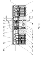
- the lock cylinder according to the invention (see Fig. 1 )
- a housing 1 in which inside and outside a respective cylinder core 2 and 3 is rotatably inserted.
- the housing 1 and the cylinder cores 2 and 3 are shown in 6-pin (ie there are six tumblers both inside and outside), but this is of course not mandatory.
- Each tumbler consists in the usual way of a core pin 15 and a housing pin 16, which are both pressed by a tumbler spring 17 in the direction of key channel or an inserted key 14.
- the measures provided for the housing pins 16 and the tumbler springs 17 corresponding holes in the housing 1 are each closed by a plug 18.
- the toothing is formed so that the dividing line between the core pin 15 and housing pin 16 at all tumblers coincides exactly with the dividing line between the cylinder core 2 and 3 and housing 1, so that the cylinder core 2 and 3 can be rotated, such as this in Fig. 1 can be seen on the left.
- the cylinder core 2 or 3 is blocked by the housing pins 16, as can be seen on the right in FIG.
- the cylinder core 2 or 3 is blocked by at least one core pin 15 or by at least one housing pin 16, depending on whether the teeth are milled too low or too deep at the appropriate location.
- the cylinder core 2 and 3 is fixed axially, it has a groove in each of which a locking ring 10 and 10 'is inserted.
- the housing 1 has for this purpose at the appropriate locations on a slot, so that the locking ring 10 and 10 'can be used and can then be supported on the flanks of the slot.
- the lock cylinder has a hollow-cylindrical driver 9 with a closing nose (in which Fig. 1 and 2 not visible).
- the driver 9 is driven by a hub 20.
- the hub 20 has externally a stepped toothing 20 "(see Fig. 2 ), and the driver 9 has inside a complementary toothing on.
- the hub 20 is thus connected to the driver 9 in a permanent rotationally fixed connection.
- a suitable key 14 (s. Fig. 1 ) is inserted, so only one cylinder core 2 or 3 is always rotatable (and the other is blocked), the hub 20 each with the cylinder core 2 or 3, in which a key is inserted, coupled and disconnected from the other cylinder core.
- the hub 20 forms part of the coupling. In Fig. 1 and 2 the hub is coupled on the left, in Fig. 1a and 2a she is coupled on the right.
- the hub 20 acts with an inner coupling part 21 and an outer coupling part 22 together. These two coupling parts 21 and 22 are connected to each other via a coupling pin 23, which ensures a predetermined distance between the two coupling parts 21 and 22.
- inner coupling part 21 a conventional Kupplungserierl is used (see Fig. 3a, 3b and 3c ).
- the protruding wings 21 'and 21 "engage in corresponding recesses of the hub 20 (see Fig. 2 ), when the coupling part 21 by the key 14 (see Fig. 1 ) is engaged (shifted to the right), as in Fig. 1 and 2 is shown. (Note: the wings 21 'and 21 "are according to the view Fig. 1 .
- the coupling part 21 (see Fig. 2 ), that is, the coupling part 21 is connected to the cylinder core 2 (see Fig. 1 ) always rotatably connected.
- the coupling and decoupling takes place between the coupling part 21 (see Fig. 2, 2a ) and the hub 20.
- the coupling part 22 is also to the right (see Fig. 2 ) (ie, in the disengaged position, as will be described below) when the coupling member 21 is displaced to the right in the engaged position.
- a cylindrical coupling body 22 ' (see Fig. 4a and 4b ) with a coupling pin 22 "and a projection 22 '" used.
- the coupling member 22 is thus always rotationally fixed to the cylinder core 3 (see Fig. 1 . 1a ) connected.
- the dimensions are chosen so that at the time of displacement of the clutch both sides are engaged; This ensures that the driver 9 can not turn unintentionally, whereby a coupling would be impossible.
- a predetermined breaking point 19 (see Fig. 1 and 2 ) intended. If you try to break out the lock cylinder, break the entire outer part (in Fig. 1 and 2 the right part), including the entire cylinder core 3.
- This predetermined breaking point 19 is realized by two cuts in the housing 1, between which a web 19 '(see Fig. 2b ) remains. This web 19 'extends obliquely to the longitudinal center plane of the housing. This causes the housing to break at the predetermined breaking point, regardless of whether the outer part of the housing is bent to the left-right or top-to-bottom.
- the hub 20 (see Fig. 1 . 1a ) is arranged axially displaceably in the housing 1.
- the sleeve-shaped extension 4 of the cylinder core 3 extends to the hub 20, so that the end face 4 '(see Fig. 2, 2a ) of the sleeve-shaped extension 4 forms a stop surface for the hub 20.
- the hub 20 is pressed with a spring 24 against this end face 4 '.
- the spring 11 ' is supported on a threaded pin 11.
- the housing bore 11 "continues in the sleeve-shaped extension 5 of the cylinder core 2, provided that it is in the starting position (which is always the case when the key is removed.)
- the upper part 12 of the sleeper essentially a cylindrical plate, which is also biased upward as a result of the spring 11 'and the lower part 13.
- the hub 20 is a blind hole 12' (see Fig. 2 ), which is offset in the normal position of the hub with respect to the bore in the cylinder core or in the housing, but in the activation position is aligned.
- the depth of the blind hole 12 ' is less than the thickness of the upper part 12 (of the cylindrical plate).
- the hub 20 is supported on the end face 4 'of the cylinder core 3 (see Fig. 1 . 1a ), and the blind hole 12 '(see Fig. 2, 2a ) is opposite the upper part 12 of the sleeper, so opposite the cylindrical plate, offset. This keeps the sleeper permanently disabled during normal operation (hence the name).
- the lock cylinder In order to remove the lock cylinder after activation of the sleeper, one must reach the inside of the lock cylinder. With the appropriate key 14, the lock cylinder can be locked, because the lower part 13 of the sleeper has a conical taper at the top, so that it is pressed upon rotation of the cylinder core 2 back into the bore in the housing 1 and does not hinder the rotation of the cylinder core 2. Thus, from the inside an emergency opening after a break-up attempt and thus an expansion of the lock cylinder is possible.
- a rotary knob cylinder has only on the outside of a conventional cylinder core 3 (see Fig. 5 ), which can be locked with a key 14; on the inside he has a knob 31, which can be turned by hand without a key.
- the cylinder core 3 according to this embodiment is designed very similar to the cylinder core 3 according to Fig. 1 ; in Fig. 5 are however the Core pins, housing pins, tumbler springs and plugs (items 15-18 in Fig. 1 ) not shown, you can see the housing bores 16 'and the core holes 15'. In the area of the key channel 14 ', the core bores 15' appear narrower.
- housing holes 16 are also present in the area of the inner side, but normally they are not used, but according to the present invention they are used, as will be explained below:
- the front part of the shaft 34 is rotatably connected to the driver 9 So the hub 20 of Fig. 1 and 2 ,
- the rotary connection can be done as usual with hubs on a stepped toothing.
- the knob 31 is thus permanently connected to the driver 9 and thus also with the locking lug 9 'in rotary connection.
- the shaft 34 rests with its free end on the end face 4 'of the cylinder core 3.
- the outer part of the lock cylinder is according to the embodiment Fig. 5 slightly shorter than in the embodiment according to Fig. 1 so that the extension pin 7 of Fig. 1 can be omitted.
- the clutch must offer a search function, because the knob can stand anywhere so that can not be engaged directly in every situation.
- first coupling part 41 and a second coupling part 42 are provided.
- the second coupling part 42 engages with wings 42 '(s. Fig. 6 ) in slots 42 "of the hollow shaft 34 in this area, the second coupling part 42 is thus non-rotatably but axially displaceably connected to the shaft 34. It is connected by a spring 43 (see FIG. Fig. 5 ) in the direction of cylinder core 3 (to the left) biased.
- the first coupling part 41 engages with a projection 41 'in a slot 41 "of the cylinder core 3.
- the first coupling part 41 is thus rotatably but axially displaceably connected to the cylinder core 3.
- a Spring 44 Between the first coupling part 41 and the second coupling part 42 there is a Spring 44. Also, the first coupling part 41 is thus in the direction Cylinder core 3 (to the left) biased.
- a predetermined breaking point 19 is provided in the housing 1. If you try to break out the lock cylinder, break the entire outer part (in Fig. 5 the left part), including the entire cylinder core 3, as shown in FIG Fig. 6 is shown.
- housing pins 16 are inserted, each by a (in Fig. 6 not shown) spring against a ball 32 are pressed, which are each inserted slightly off-center in a V-shaped recess 33 of the shaft 34.
- the shaft 34 together with the rotary knob 31 in the direction of the driver 9 with locking lug 9 '(to the left, as in FIGS. 5 and 6 shown biased), so that the shaft 34 against the end face 4 '(see Fig. 5 ) is pressed.
- a sleeper 13 ' is provided in the form of a stepped tumbler pin, which is also provided by a (in Fig. 6 not shown) spring is pushed upwards.
- a removable lock pin 38 (eg a threaded pin) forms the support for the springs.
- the shaft 34 has a groove 35 (s. Fig. 6 ), which is stepped at the closing nose 9 'side facing, so has a step 36.
- At Nutengrund are over the Circumference distributed holes 37 provided. The diameter of these holes 37 corresponds to the width of the groove 35 (without the gradation) and the diameter of the stepped end of the sleeper 13 '.
- the sleeper 13 ' is supported on the step 36.
- the shaft 34 together with the rotary knob 31 is axially fixed.
- the rotary knob cylinder according to the invention works as follows:
- the in the Fig. 7 and 8th illustrated third embodiment shows a similar knob cylinder, but in which the operation after a break-open attempt is even easier.
- the driver 9 with the locking lug 9 ' is not driven directly by the shaft 34 of the rotary knob 31, but by a hub 20.
- This hub 20 is fixedly connected by means of a pin 62 with a connecting piece 61, which in turn via another pin 63 is fixedly connected to a sleeve-shaped hub extension 64.
- the hub 20 and the hub extension 64 can therefore be considered as a solid part.
- the hub extension 64 is the shaft 34. This is secured therein by means of a pin 65, wherein the pin 65 is guided in the hub extension 64 but in slots 66. Therefore, the shaft 34 is axially slidably mounted in the hub extension 64, but non-rotatably connected thereto.
- a spring 67 which is supported on the one hand on the pin 65 (ie indirectly on the shaft 34) and on the other hand on the hub extension 64, the shaft 34 is biased in the direction of the outer cylinder core 3.
- housing bores 16 "are also present in the region of the inner side, and a sleeper 13 ', which normally slides at the end of the hub extension 64, is again inserted in one of these housing bores 16".
- the hub extension 64 translates toward the outer cylinder core three, it locks into one of the recesses 37 'of the shaft 34.
- these recesses 37 ' are U-shaped in plan view, starting from a step 59 of the shaft 34 and in the direction of this gradation 59 are open.
- a housing pin 16 is inserted, which is pressed by a spring against a ball 32, which is inserted slightly off-center in a V-shaped recess 33 of the hub extension 64.
- the Hub extension 64 together with hub 20 in the direction of the driver 9 with locking lug 9 '(to the left, as in Fig. 7 shown) biased so that the hub 20 against a ring 70 (which has a flange above) is pressed, which in turn is supported on the outer cylinder core 3.
- a fixing pin 69 is inserted in a third housing bore 16 ", which is pressed by a spring into a rectangular groove 68 of the hub extension 64.
- the diameter of the end of the fixing pin 69 is less than the width of the rectangular groove 68, so that the fixing pin 69 is the hub extension 64.
- the fixing pin 69 allows a displacement of the hub extension 64 including the hub 20 from the normal position towards the outer cylinder core 3 to some extent.
- a first coupling part 51 is axially displaceable in the cylinder core 3, but rotatably guided. This first coupling part 51 is also guided on a pin 51 'inserted centrally in the hub 20. (This pin 51 'has a slot which lies in the plane of the drawing, recognizable by the absence of hatching in this area.)
- a spring 54 which is mounted around the pin 51', pushes the first coupling part into the cylinder core 3.
- the second coupling part is realized in the form of a pin 52 which protrudes from the hub 20, but can be pressed against the force of a spring 53 in the hub 20. This pin 52 protrudes in the engaged state in a corresponding hole 55 of the first coupling part 51st
- the first coupling part 51 by the spring 54 is pressed into the cylinder core 3, so that the pin 52 is outside the hole 55 and the clutch is disengaged. If a key 14 is inserted, the first coupling part 51 is pressed in the direction of the hub 20. Since, in general, the hole 55 and the pin 52 will not be aligned, the pin 52 is pressed against the force of the spring 53 in the hub 20. Turning now the key 14, eventually the pin 52 and the hole 55 are aligned, and due to the spring 53, the pin 52 is pressed into the hole 55. Thus, the cylinder core 3 and the hub 20 are rotatably connected to each other, the clutch is engaged.
- a sleeve 8 In addition to the driver 9 is located on the side of the outer cylinder core 3, a sleeve 8, on the one hand leads the driver 9 and on the other hand serves as a stop for the hub 20 in the event of a Aufbruchtruchs. On the side of the knob 31 is located next to the driver 9, a ring 10 ", which carries the driver 9 on this page.
- the ring 70 can move until it rests with its flange against the sleeve 8.
- the hub 20 By the bias of the hub extension 64, the hub 20, the hub extension 64 and the ring 70 move to this stop.
- the sleeper 13 ' is no longer at the end of the hub extension 64 and locked - at least after a rotation of the hub 20 and thus the shaft 34 - in one of the recesses 37' a.
Abstract
Bei einem Schließzylinder mit einem Gehäuse (1), einem Mitnehmer (9) mit Schließnase (9') und mit einer Außenseite und einer In-nenseite zu beiden Seiten des Mitnehmers (9) ist zumin-dest an der Außenseite ein Zylinderkern (3) mit Zuhaltungen (15, 16, 17) vorgesehen. Im Gehäuse (1) ist an der Außenseite zwischen dem Mitnehmer (9) und der nächstgelege-nen Zuhaltung eine Sollbruchstelle (19) vorgesehen, und es ist an der Innenseite ein Schläfer (12, 13; 13') vorgesehen, der bei Wegbrechen der Außenseite sowie beim Ziehen des Zylinderkerns (3) einen ständig drehfest mit dem Mitnehmer (9) verbundenen, aber axial verschiebbaren Teil (20, 34) blockiert oder mit einem inneren Zylinderkern (2) verbindet. Zu diesem Zweck liegt der axial verschiebbare Teil (20, 34) in axialer Richtung federbelastet an der Stirnseite (4') des Zylinderkerns (3) der Außenseite direkt oder indirekt an. Der Mitnehmer ist axial unverschiebbar.

Description
Die vorliegende Erfindung betrifft einen Schließzylinder mit einem Gehäuse, einem im Gehäuse drehbaren Mitnehmer mit Schließnase und mit einer Außenseite und einer Innenseite zu beiden Seiten des Mitnehmers, wobei zumindest an der Außenseite ein Zylinderkern mit Zuhaltungen und an der Innenseite ein durch Federkraft vorgespannter Schläfer vorgesehen ist, der durch einen axial unter Federkraft verschiebbaren Teil verriegelt und zumindest teilweise im Gehäuse zurückgehalten ist und der den Schließzylinder bei Wegbrechen der Außenseite infolge Wegfalls der Verriegelung blockiert.The present invention relates to a lock cylinder with a housing, a rotatable driver in the housing with locking lug and with an outside and inside on both sides of the driver, wherein at least on the outside of a cylinder core is provided with tumblers and on the inside of a biased by spring force sleepers which is locked by an axially displaceable by spring force part and at least partially retained in the housing and blocks the lock cylinder when the outer side breaks away due to omission of the lock.
Es sind verschiedene Methoden bekannt, wie man Schließzylinder gewaltsam öffnen kann. Eine Methode ist das "Ziehen" des Zylinderkerns: man dreht eine Schraube in den Schlüsselkanal und zieht kräftig an. Dadurch werden die Zuhaltungsstifte abgeschert und der Zylinderkern kann entfernt werden.There are various methods known how to open lock cylinder forcibly. One method is to "pull" the cylinder core: turn a screw into the keyway and tighten vigorously. As a result, the tumbler pins are sheared off and the cylinder core can be removed.
Eine andere Methode besteht darin, den gesamten äußeren Teil des Schließzylinders herauszubrechen. Infolge der Schließnase ist das Gehäuse des Schließzylinders in der Mitte stark geschwächt; zusätzlich befindet sich in diesem Bereich auch noch die Gewindebohrung für die Befestigungsschraube. Wenn nun kein hochwertiger Beschlag verwendet wird, ist es relativ leicht, den äußeren Teil des Schließzylinders durch Hin- und Herbiegen herauszubrechen.Another method is to break out the entire outer part of the lock cylinder. As a result of the locking lug, the housing of the lock cylinder is greatly weakened in the middle; In addition, there is also the threaded hole for the fastening screw in this area. Now, if no high-quality fitting is used, it is relatively easy to break the outer part of the lock cylinder by bending back and forth.
Gegen letztere Aufbruchmethode werden manchmal Sollbruchstellen vorgesehen, sodass der äußere Teil nur teilweise wegbricht und somit der Mitnehmer und die Schließnase nicht direkt zugänglich sind.Against the latter breaking method, breaking points are sometimes provided, so that the outer part only partially breaks away and thus the driver and the locking lug are not directly accessible.
In der
- innerer Zylinderkern eingekuppelt und äußerer Zylinderkern ausgekuppelt
- äußerer Zylinderkern eingekuppelt und innerer Zylinderkern ausgekuppelt
- inner cylinder core coupled and disengaged outer cylinder core
- outer cylinder core engaged and disengaged inner cylinder core
Die Kupplung wird üblicher Weise vom Schlüssel verschoben; wenn innen ein Schlüssel angesteckt wird, wird sie in Richtung Außenseite des Schließzylinders verschoben und kuppelt dadurch den inneren Zylinderkern mit der Schließnase. Oft ist die Kupplung durch eine Feder in eine Richtung vorgespannt, damit sie - wenn kein Schlüssel angesteckt ist - eine definierte Lage einnimmt.The clutch is usually moved by the key; when a key is inserted inside, it is moved towards the outside of the lock cylinder and thereby couples the inner cylinder core with the locking lug. Often the coupling is biased by a spring in one direction, so that - if no key is plugged - occupies a defined position.
Gemäß der
Wie sich im Rahmen der vorliegenden Erfindung herausgestellt hat, ist diese Lösung nur ein geringer Vorteil gegenüber herkömmlichen Schließzylindern, wo die Kupplung in Richtung Außenseite vorgespannt ist. Bei letzteren Schlössern kann man die Kupplung einfach zurückdrücken und dann die Schließnase bewegen; bei dem Schließzylinder gemäß der
Dies wird durch den in Fig. 9a der
Ein Schließzylinder der eingangs genannten Art ist aus der
Die Idee der
Ein weiterer Nachteil dieses Doppelschließzylinders besteht darin, dass der Schläfer beim Ziehen des äußeren Zylinderkerns nicht aktiviert wird, es muss der gesamte äußere Teil des Doppelschließzylinders weggebrochen werden, damit der Schläfer aktiviert wird.Another disadvantage of this double-lock cylinder is that the sleeper is not activated when pulling the outer cylinder core, it must be broken off the entire outer part of the double lock cylinder, so that the sleeper is activated.
Es ist Aufgabe der vorliegenden Erfindung, die beiden beschriebenen Schließzylinder so zu verbessern, dass die Schließnase nach dem Herausbrechen des äußeren Teils nicht so leicht bewegt werden bzw. entfernt werden kann; die Schließnase soll nicht nur nach dem Herausbrechen des äußeren Teils blockiert werden, sondern auch nach dem Ziehen des äußeren Zylinderkerns; und schließlich soll eine sichere Funktion auch dann gewährleistet sein, wenn der Schließzylinder - wie üblich - in einem Einstemmschloss eingebaut ist.It is an object of the present invention to improve the two described lock cylinder so that the locking lug after the Breaking out of the outer part can not be easily moved or removed; the locking lug should not only be blocked after breaking out of the outer part, but also after pulling the outer cylinder core; and finally, a secure function should also be ensured if the lock cylinder - as usual - is installed in a one-punch lock.
Dies wird durch einen Schließzylinder der eingangs genannten Art erfindungsgemäß dadurch gelöst, dass im Gehäuse an der Außenseite zwischen dem in axialer Richtung unverschiebbaren Mitnehmer und der nächstgelegenen Zuhaltung eine Sollbruchstelle vorgesehen ist und dass der axial verschiebbare Teil gegenüber dem Mitnehmer verschiebbar und ständig drehfest in diesem gelagert ist sowie in axialer Richtung federbelastet an der Stirnseite des Zylinderkerns der Außenseite direkt oder indirekt anliegt.This is achieved by a lock cylinder of the type mentioned according to the invention that in the housing on the outside between the immovable in the axial direction driver and the nearest tumbler a predetermined breaking point is provided and that the axially displaceable part relative to the driver slidably and constantly rotatably mounted in this is spring-loaded in the axial direction on the front side of the cylinder core of the outside directly or indirectly.
Gemäß der
Wie oben erwähnt, wird bei dem Doppelschließzylinder gemäß der
Von besonderem Vorteil ist, wenn die axiale Verschiebbarkeit des ständig drehfest mit dem Mitnehmer verbundenen Teils maximal so groß ist wie der Durchmesser des Schläfers, vorzugsweise maximal halb so groß. Auf diese Weise ist ein Abscheren des Schläfers unmöglich. Da erfindungsgemäß der Schläfer nicht auf die Kupplung wirkt (die zwangsläufig einen größeren Verstellweg benötigt), kann die axiale Verschiebbarkeit des zu blockierenden Teils für den vorliegenden Zweck optimiert werden; dieser Teil bewegt sich nämlich im Normalfall nie axial, sondern nur dann, wenn ein gewaltsamer Aufbruchsversuch stattfindet. Etwas weniger als die Hälfte des Durchmessers des Schläfers wird derzeit für optimal gehalten; dann kann der Schläfer höchstens verbogen, aber niemals abgeschert werden.It is particularly advantageous if the axial displaceability of the constantly rotatably connected to the driver part is at most as large as the diameter of the sleeper, preferably at most half as large. In this way, a shearing of the sleeper is impossible. Since according to the invention the sleeper does not act on the coupling (which inevitably requires a larger displacement), the axial displaceability of the part to be blocked can be optimized for the present purpose; Normally, this part never moves axially, but only when a violent attempt at break-up takes place. Slightly less than half the sleeper's diameter is currently considered optimal; then the sleeper can be bent at most, but never sheared off.
Es ist günstig, wenn der ständig drehfest mit dem Mitnehmer verbundene Teil eine Nabe des Mitnehmers ist und beidseitig des Mitnehmers im Gehäuse geführt ist. Da der Schließzylinder infolge der Sollbruchstelle nicht genau in der Mitte bricht, sondern knapp vor dem Mitnehmer, ergibt sich dadurch eine gute Führung des Mitnehmers auch nach dem Bruch, was ein gewaltsames "Herauskippen" der Schließnase aus der Ebene, in der sie sich normalerweise dreht, erschwert.It is advantageous if the part permanently connected to the driver is non-rotatably a hub of the driver and guided on both sides of the carrier in the housing. Since the lock cylinder does not break exactly in the middle as a result of the predetermined breaking point, but just before the driver, this results in a good guidance of the driver even after the break, which makes a violent "tipping out" of the locking lug from the plane in which it normally rotates, difficult.
Wenn der Schließzylinder als Doppelschließzylinder ausgebildet ist, ist es zweckmäßig, wenn der Schläfer - bei Wegbrechen der Außenseite bzw. Ziehen des äußeren Zylinderkerns - den Zylinderkern der Innenseite mit dem ständig drehfest mit dem Mitnehmer verbundenen Teil kuppelt. Auf diese Weise kann der Schließzylinder von der Innenseite auch dann gesperrt werden, wenn der Schläfer aktiv wurde, sodass eine Notöffnung nach einem Aufbruchsversuch gewährleistet ist. Solange jedoch an der Innenseite kein Schlüssel angesteckt ist, ist der Mitnehmer blockiert.If the lock cylinder is designed as a double lock cylinder, it is expedient if the sleeper - when breaking away the outside or pulling the outer cylinder core - the cylinder core of the inside with the permanently rotatably connected to the driver part couples. In this way, the lock cylinder can be locked from the inside even when the sleeper was active, so that an emergency opening is guaranteed after a break-in attempt. However, as long as no key is attached to the inside, the driver is blocked.
Um dies konkret zu realisieren kann man vorsehen, dass der Zylinderkern der Innenseite hülsenförmig in Richtung zum Mitnehmer verlängert ist, dass sich im Bereich dieser hülsenförmigen Verlängerung die Nabe axial verschiebbar befindet, dass für den Schläfer im Bereich dieser hülsenförmigen Verlängerung eine Gehäusebohrung vorgesehen ist, die sich in der hülsenförmigen Verlängerung und in der Nabe - nach axialer Verschiebung derselben - in einem Sackloch fortsetzt, und dass der Schläfer zweiteilig ist, wobei der der Nabe zugewandte Teil eine Höhe hat, die der Dicke der hülsenförmigen Verlängerung entspricht. Durch diese Ausführungsform ist es also - im Gegensatz zur
Damit bei dieser Lösung aber nicht der innere Zylinderkern durch den unteren Teil des Schläfers blockiert wird, ist es zweckmäßig, dass der der Nabe abgewandte Teil des Schläfers an der der Nabe zugewandten Seite konusförmig ausgebildet ist. Auf Grund des Konus wird der untere Teil des Schläfers zurückgedrückt, wenn der Zylinderkern gedreht wird.So that in this solution but not the inner cylinder core is blocked by the lower part of the sleeper, it is expedient that the hub facing away from the part of the sleeper is formed on the side facing the hub cone-shaped. Due to the cone, the lower part of the sleeper is pushed back when the cylinder core is rotated.
Wenn der Schließzylinder als Drehknopfzylinder ausgebildet ist und der an der Innenseite vorgesehene Drehknopf über eine Welle ständig mit dem Mitnehmer in Drehverbindung steht, ist es zweckmäßig, wenn der Schläfer - bei Wegbrechen der Außenseite bzw. Ziehen des äußeren Zylinderkerns - die Welle blockiert, gegebenenfalls nach einer Drehung der Welle um maximal 30°. In diesem Fall ist also kein gesonderter Bauteil notwendig, es wird die Welle des Drehknopfs blockiert.If the lock cylinder is designed as a rotary knob cylinder and the rotary knob provided on the inside is constantly in rotary connection with the driver via a shaft, it is expedient if the sleeper - when the outer side or the outer cylinder core pulls away - blocks the shaft, if necessary a rotation of the shaft by a maximum of 30 °. In this case, so no separate component is necessary, it is blocked the shaft of the knob.
Damit der Schließzylinder dennoch nach Aktivierung des Schläfers von der Innenseite her demontiert werden kann ist es zweckmäßig, wenn der Schläfer nach seiner Aktivierung von der Innenseite lösbar ist, sodass eine Notöffnung nach einem Aufbruchsversuch gewährleistet ist.So that the lock cylinder can still be dismantled after activation of the sleeper from the inside, it is expedient if the sleeper is releasable after its activation from the inside, so that an emergency opening is ensured after a break-up attempt.
Dies kann in zweckmäßiger Weise so realisiert werden, dass in der Welle an einer Abstufung ein Kranz U-förmiger Ausnehmungen vorgesehen ist, wobei die Ausnehmungen mit der offenen Seite des U von dieser Abstufung ausgehen, dass der Schläfer - bei Wegbrechen der Außenseite bzw. Ziehen des äußeren Zylinderkerns - in eine dieser Ausnehmungen einrastet, und dass der Drehknopf samt Welle gegen Federkraft axial aus dem Schließzylinder herausziehbar ist, bis der Schläfer außer Eingriff aus der einen Ausnehmung kommt. Auf diese Weise kann man das Schloss nach einem gewaltsamen Aufbruchsversuch ganz einfach öffnen, indem man den Drehknopf herauszieht und dann wie gewohnt dreht.This can be realized in an expedient manner so that a ring of U-shaped recesses is provided in the shaft at a gradation, the recesses with the open side of the U starting from this gradation that the sleeper - when breaking away the outside or pulling of the outer cylinder core - engages in one of these recesses, and that the rotary knob together with the shaft against spring force is axially pulled out of the lock cylinder until the sleeper disengaged from a recess. In this way you can open the lock after a violent escape attempt simply by pulling the knob and then turn as usual.
Schließlich ist es zweckmäßig, wenn der Abstand der Sollbruchstelle von der Mitte der Schließnase 7-12 mm beträgt. Damit bleiben - von der Mitte der Schließnase aus gesehen - 7-12 mm stehen, wenn der äußere Teil des Schließzylinders weggebrochen wird. Schließzylinder und zugehörige Zylinderschlösser sind genormt. Wenn solch ein Schließzylinder in ein normgerechtes Zylinderschloss eingebaut ist und dann an der Sollbruchstelle gebrochen wird, bricht er in unmittelbarer Nähe des Schlosskastens, aber dennoch nicht so nahe am Schlosskasten, dass der verbleibende Schließzylinder in die Öffnung des Schlosskastens gekippt werden kann.Finally, it is expedient if the distance of the predetermined breaking point from the center of the closing nose is 7-12 mm. This leaves - seen from the middle of the locking nose - 7-12 mm, when the outer part of the lock cylinder is broken away. Locking cylinder and associated cylinder locks are standardized. If such a lock cylinder is installed in a standard cylinder lock and is then broken at the predetermined breaking point, it breaks in the immediate vicinity of the lock box, but not so close to the lock box that the remaining lock cylinder can be tilted into the opening of the lock box.
Zuletzt ist es auch günstig, wenn die beiden Teile des Gehäuses zu beiden Seiten der Sollbruchstelle durch einen Steg miteinander verbunden sind, der schräg zur Längsmittelebene des Gehäuses verläuft. Bei dieser Ausbildung bricht das Gehäuse an der Sollbruchstelle unabhängig davon, ob der äußere Teil des Gehäuses links-rechts oder oben-unten hin und her gebogen wird.Finally, it is also advantageous if the two parts of the housing connected to each other on both sides of the predetermined breaking point by a web are, which extends obliquely to the longitudinal center plane of the housing. In this design, the housing breaks at the predetermined breaking point regardless of whether the outer part of the housing is bent left-right or top-bottom back and forth.
An Hand der beiliegenden Zeichnungen wird die vorliegende Erfindung näher erläutert. Es zeigt:
-
Fig. 1 einen Längsschnitt durch eine erste Ausführungsform eines erfindungsgemäßen Schließzylinders mit links eingestecktem Schlüssel; -
Fig. 1a denselben ohne Schlüssel; -
Fig. 2 das Detail II vonFig. 1 in vergrößertem Maßstab; -
Fig. 2a dasselbe ohne eingesteckten Schlüssel; -
Fig. 2b einen Schnitt entlang der Linie IIb-IIb vonFig. 1a ; -
Fig. 3a bis 3c den inneren Kupplungsteil; -
Fig. 4a und 4b den äußeren Kupplungsteil; -
Fig. 5 einen Längsschnitt durch eine zweite Ausführungsform der vorliegenden Erfindung; -
Fig. 6 dasselbe, jedoch mit weggebrochenem äußeren Teil, wobei außerdem die Welle des Drehknopfs nicht geschnitten, sondern in Ansicht dargestellt ist; -
Fig. 7 einen Längsschnitt durch eine dritte Ausführungsform der vorliegenden Erfindung; und -
Fig. 8 den Drehknopf samt Welle gemäß der dritten Ausführungsform in perspektivischer Ansicht.
-
Fig. 1 a longitudinal section through a first embodiment of a lock cylinder according to the invention with left inserted key; -
Fig. 1a the same without a key; -
Fig. 2 the detail II ofFig. 1 on an enlarged scale; -
Fig. 2a the same without the key inserted; -
Fig. 2b a section along the line IIb-IIb ofFig. 1a ; -
Fig. 3a to 3c the inner coupling part; -
Fig. 4a and 4b the outer coupling part; -
Fig. 5 a longitudinal section through a second embodiment of the present invention; -
Fig. 6 the same, but with the outer part broken away, and in addition the shaft of the rotary knob is not cut but shown in view; -
Fig. 7 a longitudinal section through a third embodiment of the present invention; and -
Fig. 8 the knob with shaft according to the third embodiment in a perspective view.
Der erfindungsgemäße Schließzylinder (siehe
Damit der Zylinderkern 2 bzw. 3 axial fixiert ist, weist er eine Nut auf, in die jeweils ein Sicherungsring 10 bzw. 10' eingesetzt ist. Das Gehäuse 1 weist zu diesem Zweck an den entsprechenden Stellen einen Schlitz auf, sodass der Sicherungsring 10 bzw. 10' eingesetzt werden kann und sich danach an den Flanken des Schlitzes abstützen kann.Thus, the
Damit der Zylinderkern 2 bzw. 3 das zugehörige Zylinderschloss betätigen kann, weist der Schließzylinder einen hohlzylindrischen Mitnehmer 9 mit einer Schließnase (in den
Da im Normalfall immer nur entweder innen oder außen ein passender Schlüssel 14 (s.
Die Nabe 20 (siehe
Auf der Außenseite steht für ein Kupplungsflügerl nicht genügend Platz zur Verfügung, aus diesem Grunde wird als Kupplungsteil 22 ein zylindrischer Kupplungskörper 22' (siehe
Die Abmessungen sind dabei so gewählt, dass bei der Verschiebung der Kupplung kurzfristig beide Seiten eingekuppelt sind; dadurch wird sichergestellt, dass sich der Mitnehmer 9 nicht unbeabsichtigt verdrehen kann, wodurch ein Einkuppeln unmöglich gemacht würde.The dimensions are chosen so that at the time of displacement of the clutch both sides are engaged; This ensures that the
Soweit entspricht dieser Schließzylinder - mit Ausnahme der asymmetrisch ausgebildeten Kupplung - weitgehend dem Stand der Technik.As far as corresponds to this lock cylinder - with the exception of the asymmetrical coupling - largely the prior art.
Weiters ist eine Sollbruchstelle 19 (siehe
Diese Sollbruchstelle 19 wird durch zwei Einschnitte im Gehäuse 1 realisiert, zwischen denen ein Steg 19' (siehe
Auch dies ist Stand der Technik.This too is state of the art.
Um nun den Schließzylinder auch bei Herausbrechen der äußeren Zylinderhälfte (in
Die Nabe 20 (siehe
Neben dem Mitnehmer 9 befindet sich eine Hülse 8. Diese hat zur Verzahnung 20" der Nabe 20 einen Abstand 25. Wenn nach Wegbrechen der äußeren Schließzylinderhälfte die als Anschlagfläche wirkende Stirnseite 4' wegfällt, bewegt sich die Nabe 20 auf Grund der Feder 24 aus der Normalstellung (wie dargestellt) um den Abstand 25 nach rechts in die Aktivierungsstellung, bis die Verzahnung 20" an der Hülse 8 anliegt. In
In der inneren Schließzylinderhälfte ist eine zusätzliche Zuhaltung (siehe
Die erfindungsgemäßen Merkmale funktionieren wie folgt:The features of the invention function as follows:
Solange der Schließzylinder intakt ist, stützt sich die Nabe 20 an der Stirnseite 4' des Zylinderkerns 3 (siehe
Wenn jedoch der äußere Teil des Schließzylinders an der Sollbruchstelle 19 weggebrochen wird, wird auch der gesamte Zylinderkern 3 (siehe
Um nach Aktivierung des Schläfers den Schließzylinder auszubauen, muss man zur Innenseite des Schließzylinders gelangen. Mit dem passenden Schlüssel 14 lässt sich der Schließzylinder sperren, denn der untere Teil 13 des Schläfers weist oben eine kegelförmige Verjüngung auf, sodass er bei Drehung des Zylinderkerns 2 zurück in die Bohrung im Gehäuse 1 gedrückt wird und die Drehung des Zylinderkerns 2 nicht behindert. Somit ist von der Innenseite eine Notöffnung nach einem Aufbruchsversuch und somit ein Ausbau des Schließzylinders möglich.In order to remove the lock cylinder after activation of the sleeper, one must reach the inside of the lock cylinder. With the
An Hand der
Für Drehknopfzylinder wählt man in der Serienfertigung aus Kostengründen meist dasselbe Gehäuse 1 wie bei Doppelzylindern, wobei statt des inneren Zylinderkerns der Drehknopf 31 mit einer Welle 34 eingesetzt wird. Daher sind auch im Bereich der Innenseite Gehäusebohrungen 16" vorhanden. Normalerweise sind diese ohne Verwendung, gemäß der vorliegenden Erfindung kommen sie jedoch zum Einsatz, wie dies weiter unten erläutert wird. Der vordere Teil der Welle 34 steht mit dem Mitnehmer 9 in Drehverbindung, ersetzt also die Nabe 20 von
Der äußere Teil des Schließzylinders ist bei der Ausführungsform gemäß
Aus diesem Grunde sind ein erster Kupplungsteil 41 und ein zweiter Kupplungsteil 42 vorgesehen. Der zweite Kupplungsteil 42 greift mit Flügeln 42' (s.
Der erste Kupplungsteil 41 greift mit einem Vorsprung 41' in einen Schlitz 41" des Zylinderkerns 3 ein. Der erste Kupplungsteil 41 ist somit drehfest, aber axial verschiebbar mit dem Zylinderkern 3 verbunden. Zwischen dem ersten Kupplungsteil 41 und dem zweiten Kupplungsteil 42 befindet sich eine Feder 44. Auch der erste Kupplungsteil 41 ist somit in Richtung Zylinderkern 3 (nach links) vorgespannt.The
In der dargestellten Lage, wenn der Schlüssel 14 gegen den ersten Kupplungsteil 41 drückt, ist dieser mit dem zweiten Kupplungsteil 42 drehfest verbunden, weil ein Flügel 45 des ersten Kupplungsteils 41 in einen entsprechenden Schlitz des zweiten Kupplungsteils 42 eingreift.In the illustrated position, when the key 14 presses against the
Wenn der Schlüssel 14 angesteckt wird, stehen jedoch der Flügel 45 und der entsprechende Schlitz normalerweise nicht einander gegenüber. In diesem Fall drückt der Schlüssel 14 beide Kupplungsteile 41 und 42 nach rechts (entgegen der Kraft der Feder 43). Wird nun der Schlüssel 14 gedreht, kommen der Flügel 45 und der entsprechende Schlitz irgendwann einander gegenüber zu liegen; da die Feder 43 stärker ist als die Feder 44, wird nun der zweite Kupplungsteil 42 nach links (wie in
Weiters ist im Gehäuse 1 eine Sollbruchstelle 19 vorgesehen. Wird versucht, den Schließzylinder herauszubrechen, bricht man den gesamten äußeren Teil (in
Soweit entspricht der Drehknopfzylinder weitgehend dem Stand der Technik.As far as the rotary knob cylinder largely corresponds to the prior art.
Erfindungsgemäß sind in zwei Gehäusebohrungen 16" (s.
Weiters ist ein Schläfer 13' in Form eines abgestuften Zuhaltungsstiftes vorgesehen, der ebenso durch eine (in
Der erfindungsgemäße Drehknopfzylinder funktioniert wie folgt:The rotary knob cylinder according to the invention works as follows:
Solange der Schließzylinder intakt ist, stützt sich der Schläfer 13' an der Stufe 36 ab, die Welle 34 samt Drehknopf 31 lässt sich frei drehen und nimmt den Mitnehmer 9 samt der Schließnase 9' mit.As long as the lock cylinder is intact, the sleeper 13 'is supported on the step 36, the
Wird der äußere Teil des Drehknopfzylinders herausgebrochen, reißt dieser an der Sollbruchstelle 19 (siehe
Das Vorsehen der Löcher 37 in der Nut 35 (und nicht am Außenumfang der Welle 34) hat den Vorteil, dass die Trennfläche zwischen dem Schläfer 13' und der Welle 34 nicht zugänglich ist. Es ist daher nicht möglich, ein dünnes Blättchen zwischen der Welle 34 und dem Gehäuse 1 bis zu den Löchern 37 einzuschieben, um ein Einrasten des Schläfers 13' in eines der Löcher 37 zu verhindern.The provision of the
Um den Schließzylinder nach einem Aufbruchsversuch (also nach Aktivierung des Schläfers 13') zu demontieren, muss man auch hier an die Innenseite des Schließzylinders gelangen. Dann kann man den Verschlussstift 38 herausnehmen: Dadurch verlieren die Federn ihr Widerlager, der Schläfer 13' fällt aus dem Loch 37 heraus und der Drehknopf 31 lässt sich wieder drehen. Somit ist auch hier nach einem Aufbruchsversuch eine Notöffnung und somit eine Demontage desIn order to disassemble the lock cylinder after a break-up attempt (ie after activation of the sleeper 13 '), one must also get to the inside of the lock cylinder here. Then you can take out the lock pin 38: As a result, the springs lose their abutment, the sleeper 13 'falls out of the
Schließzylinders möglich.Locking cylinder possible.
Die in den
Zu diesem Zweck wird der Mitnehmer 9 mit der Schließnase 9' nicht direkt von der Welle 34 des Drehknopfs 31 angetrieben, sondern von einer Nabe 20. Diese Nabe 20 ist mittels eines Stifts 62 mit einem Verbindungsstück 61 fest verbunden, das seinerseits über einen weiteren Stift 63 mit einer hülsenförmigen Nabenverlängerung 64 fest verbunden ist. Die Nabe 20 und die Nabenverlängerung 64 können daher als ein fester Teil betrachtet werden. In der Nabenverlängerung 64 befindet sich die Welle 34. Diese ist darin mittels eines Stifts 65 befestigt, wobei der Stift 65 in der Nabenverlängerung 64 aber in Langlöchern 66 geführt ist. Daher ist die Welle 34 in der Nabenverlängerung 64 axial verschiebbar gelagert, aber dennoch drehfest mit dieser verbunden. Durch eine Feder 67, die sich einerseits am Stift 65 (also indirekt an der Welle 34) und andererseits an der Nabenverlängerung 64 abstützt, ist die Welle 34 in Richtung zum äußeren Zylinderkern 3 vorgespannt.For this purpose, the
Wie bereits bei der zweiten Ausführungsform erwähnt, wählt man für Drehknopfzylinder in der Serienfertigung aus Kostengründen meist dasselbe Gehäuse 1 wie bei Doppelzylindern. Daher sind auch im Bereich der Innenseite Gehäusebohrungen 16" vorhanden. In einer dieser Gehäusebohrungen 16" ist wiederum ein Schläfer 13' eingesetzt, der im Normalfall am Ende der Nabenverlängerung 64 gleitet. Wenn sich die Nabenverlängerung 64 jedoch in Richtung zum äußeren Zylinderkern drei verlagert, rastet er in einer der Ausnehmungen 37' der Welle 34 ein. Wie in
Weiters ist in einer anderen Gehäusebohrung 16" ein Gehäusestift 16 eingesetzt, der durch eine Feder gegen eine Kugel 32 gedrückt wird, welche etwas außermittig in eine V-förmige Vertiefung 33 der Nabenverlängerung 64 eingesetzt ist. Dadurch wird die Nabenverlängerung 64 samt Nabe 20 in Richtung zum Mitnehmer 9 mit Schließnase 9' (nach links, wie in
Schließlich ist in einer dritten Gehäusebohrung 16" ein Fixierstift 69 eingesetzt, der durch eine Feder in eine Rechtecknut 68 der Nabenverlängerung 64 gedrückt wird. Der Durchmesser des Endes des Fixierstiftes 69 ist geringer als die Breite der Rechtecknut 68, sodass der Fixierstift 69 die Nabenverlängerung 64 und somit die Nabe 20 mit einem gewissen Spiel axial fixiert. Infolge des Fixierstiftes 69 ist es unmöglich, den Drehknopf 31 samt Nabe 20 und Nabenverlängerung 64 aus dem Schließzylinder herauszuziehen, der Fixierstift 69 lässt aber eine Verschiebung der Nabenverlängerung 64 samt Nabe 20 von der Normalposition in Richtung zum äußeren Zylinderkern 3 in einem gewissen Ausmaß zu.Finally, a fixing
Der links dargestellte (äußere) Zylinderkern 3, der wie üblich durch einen Sicherungsring 10 axial fixiert ist, kann in üblicher Weise durch einen Schlüssel 14, der in einen Schlüsselkanal 14' eingesteckt ist, betätigt werden, weil der Schlüssel 14 die Kernstifte 15 und die Gehäusestifte 16 so anordnet, dass deren Trennflächen genau an der Grenzfläche des Zylinderkerns 3 liegen.The illustrated on the left (outer)
Die Kupplung ist hier wie folgt realisiert: Ein erster Kupplungsteil 51 ist im Zylinderkern 3 axial verschiebbar, aber drehfest geführt. Dieser erste Kupplungsteil 51 ist außerdem an einem zentral in der Nabe 20 eingesetzten Stift 51' geführt. (Dieser Stift 51' weist einen Schlitz auf, der in der Zeichenebene liegt, erkennbar am Fehlen der Schraffur in diesem Bereich.) Eine Feder 54, die um den Stift 51' angebracht ist, drückt den ersten Kupplungsteil in den Zylinderkern 3 hinein. Der zweite Kupplungsteil ist in Form eines Stiftes 52 realisiert, der aus der Nabe 20 hervorragt, aber entgegen der Kraft einer Feder 53 in die Nabe 20 gedrückt werden kann. Dieser Stift 52 ragt im eingekuppelten Zustand in ein entsprechendes Loch 55 des ersten Kupplungsteils 51.The coupling is realized here as follows: A first coupling part 51 is axially displaceable in the
Ist kein Schlüssel 14 eingeschoben, wird der erste Kupplungsteil 51 durch die Feder 54 in den Zylinderkern 3 gedrückt, sodass der Stift 52 außerhalb des Lochs 55 liegt und die Kupplung ausgekuppelt ist. Wird ein Schlüssel 14 eingeschoben, wird der erste Kupplungsteil 51 in Richtung Nabe 20 gedrückt. Da im Allgemeinen das Loch 55 und der Stift 52 nicht fluchten werden, wird der Stift 52 entgegen der Kraft der Feder 53 in die Nabe 20 gedrückt. Dreht man nun den Schlüssel 14, fluchten irgendwann der Stift 52 und das Loch 55, und infolge der Feder 53 wird der Stift 52 in das Loch 55 gedrückt. Damit sind der Zylinderkern 3 und die Nabe 20 drehfest miteinander verbunden, die Kupplung ist eingekuppelt.If no key 14 is inserted, the first coupling part 51 by the spring 54 is pressed into the
Neben dem Mitnehmer 9 befindet sich an der Seite zum äußeren Zylinderkern 3 eine Hülse 8, die einerseits den Mitnehmer 9 führt und andererseits als Anschlag für die Nabe 20 im Falle eines Aufbruchsversuchs dient. An der Seite zum Drehknopf 31 befindet sich neben dem Mitnehmer 9 ein Ring 10", der den Mitnehmer 9 an dieser Seite führt.In addition to the
Im Normalfall befinden sich alle Teile in der in
Wird jedoch der äußere Zylinderkern 3 bei einem Aufbruchsversuch entfernt (sei es durch Kernziehen, sei es durch Wegbrechen des gesamten äußeren Teils an der Sollbruchstelle 19), kann sich der Ring 70 verschieben, bis er mit seinem Flansch an der Hülse 8 anliegt. Durch die Vorspannung der Nabenverlängerung 64 bewegen sich die Nabe 20, die Nabenverlängerung 64 und der Ring 70 bis zu diesem Anschlag. Dadurch liegt der Schläfer 13' nicht mehr länger am Ende der Nabenverlängerung 64 auf und rastet - jedenfalls nach einer Verdrehung der Nabe 20 und damit der Welle 34 - in einer der Ausnehmungen 37' ein.However, if the
Um das Schloss von innen zu öffnen, braucht man nur den Drehknopf 31 nach innen zu ziehen, denn infolge der in Richtung zur Abstufung 59 offenen Löcher 37 kommt der Schläfer 13' dadurch außer Eingriff, und der Drehknopf 31 kann wie üblich gedreht und das Schloss somit geöffnet werden.To open the lock from the inside, you only need to turn the
- 11
- Gehäusecasing
- 22
- Zylinderkern, innenCylinder core, inside
- 33
- Zylinderkern, außenCylinder core, outside
- 3'3 '
- Ausnehmungrecess
- 44
- Hülsenförmige VerlängerungSleeve-shaped extension
- 4'4 '
- Stirnseitefront
- 55
- Hülsenförmige VerlängerungSleeve-shaped extension
- 66
- Verlängerungsstiftextension pin
- 77
- Verlängerungsstiftextension pin
- 88th
- Hülseshell
- 99
- Mitnehmertakeaway
- 9'9 '
- SchließnaseCam
- 10, 10'10, 10 '
- Sicherungsringcirclip
- 10"10 "
- Ringring
- 1111
- GewindestiftSet screw
- 11'11 '
- Federfeather
- 11"11 "
- Gehäusebohrunghousing bore
- 1212
- Oberer Teil des SchläfersUpper part of the sleeper
- 12'12 '
- Sacklochblind
- 1313
- Unterer Teil des SchläfersLower part of the sleeper
- 13'13 '
- Schläfersleeper
- 1414
- Schlüsselkey
- 14'14 '
- Schlüsselkanalkeyway
- 1515
- Kernstiftcore pin
- 15'15 '
- Kernbohrungcore drilling
- 1616
- Gehäusestifthousing pin
- 16'16 '
- Gehäusebohrunghousing bore
- 16"16 "
- Gehäusebohrunghousing bore
- 1717
- Zuhaltungsfedertumbler
- 1818
- StopfenPlug
- 1919
- SollbruchstelleBreaking point
- 19'19 '
- Stegweb
- 2020
- Nabehub
- 20'20 '
- Bohrung in 20Bore in 20
- 20"20 "
- Verzahnunggearing
- 2121
- innerer Kupplungsteilinner coupling part
- 21', 21"21 ', 21 "
- Flügel von 21Wing of 21
- 2222
- äußerer Kupplungsteilouter coupling part
- 22'22 '
- Kupplungskörper von 22Coupling body of 22
- 22"22 "
- Kupplungsstift von 22Coupling pin of 22
- 22'"22 ''
- Vorsprung von 22Advantage of 22
- 2323
- Kupplungsstiftcoupling pin
- 2424
- Federfeather
- 2525
- Abstanddistance
- 3131
- Drehknopfknob
- 3232
- KugelBullet
- 3333
- V-förmige VertiefungV-shaped recess
- 3434
- Welle des DrehknopfsWave of the knob
- 3535
- Nutgroove
- 3636
-
Stufe der Nut 35Step of the
groove 35 - 3737
- Löcherholes
- 37'37 '
- Ausnehmungrecess
- 3838
- Verschlussstiftlocking pin
- 4141
- erster Kupplungsteilfirst coupling part
- 41'41 '
- Vorsprung von 41Advantage of 41
- 41"41 "
- Schlitzslot
- 4242
- zweiter Kupplungsteilsecond coupling part
- 42'42 '
- Flügelwing
- 42"42 "
- Schlitzslot
- 4343
- Federfeather
- 4444
- Federfeather
- 4545
- Flügelwing
- 5151
- erster Kupplungsteilfirst coupling part
- 51'51 '
- Stiftpen
- 5252
- Stiftpen
- 5353
- Federfeather
- 5454
- Federfeather
- 5555
- Lochhole
- 5959
- Abstufunggradation
- 6161
- Verbindungsstückjoint
- 6262
- Stiftpen
- 6363
- Stiftpen
- 6464
- Nabenverlängerunghub extension
- 6565
- Stiftpen
- 6666
- Langlöcher in 64Long holes in 64
- 6767
- Federfeather
- 6868
- Rechtecknutrectangular groove
- 6969
- Fixierstiftlocating pin
- 7070
- Ringring
Claims (11)
Applications Claiming Priority (1)
| Application Number | Priority Date | Filing Date | Title |
|---|---|---|---|
| ATGM50112/2013U AT14128U1 (en) | 2013-08-23 | 2013-08-23 | lock cylinder |
Publications (3)
| Publication Number | Publication Date |
|---|---|
| EP2840204A2 true EP2840204A2 (en) | 2015-02-25 |
| EP2840204A3 EP2840204A3 (en) | 2015-08-05 |
| EP2840204B1 EP2840204B1 (en) | 2016-10-05 |
Family
ID=51390033
Family Applications (1)
| Application Number | Title | Priority Date | Filing Date |
|---|---|---|---|
| EP14182009.2A Active EP2840204B1 (en) | 2013-08-23 | 2014-08-22 | Lock cylinder |
Country Status (2)
| Country | Link |
|---|---|
| EP (1) | EP2840204B1 (en) |
| AT (1) | AT14128U1 (en) |
Cited By (6)
| Publication number | Priority date | Publication date | Assignee | Title |
|---|---|---|---|---|
| GB2545389A (en) * | 2015-09-07 | 2017-06-21 | Banham Patent Locks Ltd | Security mechanism |
| GB2548224A (en) * | 2016-03-11 | 2017-09-13 | O'sullivan Mark | Further improved locks and locking mechanisms |
| WO2018051094A1 (en) * | 2016-09-15 | 2018-03-22 | Apecs Consult Limited | Anti-snap cylinder lock |
| WO2019073494A1 (en) * | 2017-10-10 | 2019-04-18 | Cisa S.P.A. | Anti-intrusion cylinder |
| EP3517713A1 (en) * | 2018-01-29 | 2019-07-31 | C. Ed. Schulte Gesellschaft mit beschränkter Haftung Zylinderschlossfabrik | Closing device |
| EP3680424A1 (en) * | 2019-01-10 | 2020-07-15 | Federal Lock Co., Ltd. | Auto locked lock cylinder after destruction |
Families Citing this family (2)
| Publication number | Priority date | Publication date | Assignee | Title |
|---|---|---|---|---|
| DE102022114905A1 (en) | 2021-06-29 | 2022-12-29 | C.Ed. Schulte Gesellschaft mit beschränkter Haftung Zylinderschlossfabrik | Lock with a bolt that can be rotated by an operating element |
| EP4112856A1 (en) | 2021-06-29 | 2023-01-04 | C.Ed. Schulte Gesellschaft mit beschränkter Haftung Zylinderschlossfabrik | Lock with a bolt rotatable by an actuating element |
Citations (2)
| Publication number | Priority date | Publication date | Assignee | Title |
|---|---|---|---|---|
| WO2009156731A2 (en) | 2008-06-26 | 2009-12-30 | Avocet Hardware Ltd | Lock mechanism |
| EP2466039A2 (en) | 2010-12-17 | 2012-06-20 | Talleres De Escoriaza, S.A. | Security device for lock cylinder |
Family Cites Families (1)
| Publication number | Priority date | Publication date | Assignee | Title |
|---|---|---|---|---|
| GB2318824B (en) * | 1996-11-02 | 2001-01-31 | Anglian Windows Ltd | Euro-cylinder door locks |
-
2013
- 2013-08-23 AT ATGM50112/2013U patent/AT14128U1/en not_active IP Right Cessation
-
2014
- 2014-08-22 EP EP14182009.2A patent/EP2840204B1/en active Active
Patent Citations (2)
| Publication number | Priority date | Publication date | Assignee | Title |
|---|---|---|---|---|
| WO2009156731A2 (en) | 2008-06-26 | 2009-12-30 | Avocet Hardware Ltd | Lock mechanism |
| EP2466039A2 (en) | 2010-12-17 | 2012-06-20 | Talleres De Escoriaza, S.A. | Security device for lock cylinder |
Cited By (12)
| Publication number | Priority date | Publication date | Assignee | Title |
|---|---|---|---|---|
| GB2545389A (en) * | 2015-09-07 | 2017-06-21 | Banham Patent Locks Ltd | Security mechanism |
| GB2545389B (en) * | 2015-09-07 | 2021-06-23 | Banham Patent Locks Ltd | Security mechanism |
| GB2548224A (en) * | 2016-03-11 | 2017-09-13 | O'sullivan Mark | Further improved locks and locking mechanisms |
| GB2548159A (en) * | 2016-03-11 | 2017-09-13 | O'sullivan Mark | Improved locks and locking mechanisms |
| GB2548159B (en) * | 2016-03-11 | 2018-03-07 | Osullivan Marcus | A Cylinder Lock with Cam Securing Mechanism |
| GB2548224B (en) * | 2016-03-11 | 2019-06-26 | Mark Osullivan | A cylinder lock with cam securing mechanism |
| WO2018051094A1 (en) * | 2016-09-15 | 2018-03-22 | Apecs Consult Limited | Anti-snap cylinder lock |
| GB2553812B (en) * | 2016-09-15 | 2021-03-24 | Apecs Consult Ltd | Anti-snap cylinder lock |
| WO2019073494A1 (en) * | 2017-10-10 | 2019-04-18 | Cisa S.P.A. | Anti-intrusion cylinder |
| EP3517713A1 (en) * | 2018-01-29 | 2019-07-31 | C. Ed. Schulte Gesellschaft mit beschränkter Haftung Zylinderschlossfabrik | Closing device |
| EP3789568A1 (en) | 2018-01-29 | 2021-03-10 | C. Ed. Schulte Gesellschaft mit beschränkter Haftung Zylinderschlossfabrik | Locking cylinder |
| EP3680424A1 (en) * | 2019-01-10 | 2020-07-15 | Federal Lock Co., Ltd. | Auto locked lock cylinder after destruction |
Also Published As
| Publication number | Publication date |
|---|---|
| AT14128U1 (en) | 2015-04-15 |
| EP2840204A3 (en) | 2015-08-05 |
| EP2840204B1 (en) | 2016-10-05 |
Similar Documents
| Publication | Publication Date | Title |
|---|---|---|
| EP2840204B1 (en) | Lock cylinder | |
| EP2020474B1 (en) | Lock | |
| EP2019178B1 (en) | Lock with articulated rods | |
| DE69926773T2 (en) | CYLINDER LOCK WITH BURGLARY LOCK | |
| AT513607B1 (en) | cylinder lock | |
| DE202011106812U1 (en) | Wendenschloss | |
| EP2868850B1 (en) | Padlock | |
| EP3258036B1 (en) | Fitting with a fitting lock | |
| DE2530116A1 (en) | EMERGENCY KEY DEVICE ON A CYLINDER LOCK WITH DOUBLE LOCKING CYLINDER | |
| EP2218850B1 (en) | Locking system with coupling device for a double closing cylinder with emergency and danger function comprising two cylinder cores and with corresponding key | |
| DE202005020043U1 (en) | Bolting device for e.g. cabinets has movable pin that allows or prevents torque transfer between rotor and knob when rotor and knob are respectively coupled or uncoupled | |
| DE102015001960A1 (en) | Locking cylinder with two on the same axis spaced locking lugs | |
| EP3517713B1 (en) | Closing device | |
| EP2166179A1 (en) | Lock cylinder, in particular for a door lock | |
| DE102015121175A1 (en) | Security fitting for panic lock | |
| EP0036141B1 (en) | Lock device for casement fastener, bar shutters and the like | |
| EP3550097B1 (en) | Closing device | |
| EP0569997B1 (en) | Lock cylinder, locking installation, key and method of producing a combination of a lock cylinder and its corresponding key | |
| DE102006003836A1 (en) | Cylinder lock for e.g. vehicle doors, has closing and opening mechanism with cylinder, and output unit provided at lower end side of cylinder, where connection between main part of cylinder and rear edge part is released | |
| EP3535463B1 (en) | Locking unit for a motor vehicle | |
| DE202015001220U1 (en) | Lock cylinder with two spaced on the same axis spaced locking lugs | |
| DE102018131779A1 (en) | Locking device | |
| EP0296337B1 (en) | Profile locking cylinder | |
| DE102010015463B4 (en) | Swivel lever lock with rotation prevention for the actuating shaft | |
| EP3812537A1 (en) | Locking cylinder |
Legal Events
| Date | Code | Title | Description |
|---|---|---|---|
| PUAI | Public reference made under article 153(3) epc to a published international application that has entered the european phase |
Free format text: ORIGINAL CODE: 0009012 |
|
| 17P | Request for examination filed |
Effective date: 20140822 |
|
| AK | Designated contracting states |
Kind code of ref document: A2 Designated state(s): AL AT BE BG CH CY CZ DE DK EE ES FI FR GB GR HR HU IE IS IT LI LT LU LV MC MK MT NL NO PL PT RO RS SE SI SK SM TR |
|
| AX | Request for extension of the european patent |
Extension state: BA ME |
|
| GBCC | Gb: corrected translation (of claims) filed (gb section 80(3)/1977) | ||
| PUAL | Search report despatched |
Free format text: ORIGINAL CODE: 0009013 |
|
| AK | Designated contracting states |
Kind code of ref document: A3 Designated state(s): AL AT BE BG CH CY CZ DE DK EE ES FI FR GB GR HR HU IE IS IT LI LT LU LV MC MK MT NL NO PL PT RO RS SE SI SK SM TR |
|
| AX | Request for extension of the european patent |
Extension state: BA ME |
|
| RIC1 | Information provided on ipc code assigned before grant |
Ipc: E05B 9/04 20060101ALI20150626BHEP Ipc: E05B 9/10 20060101AFI20150626BHEP Ipc: E05B 17/20 20060101ALI20150626BHEP Ipc: E05B 17/00 20060101ALI20150626BHEP Ipc: E05B 27/00 20060101ALI20150626BHEP |
|
| R17P | Request for examination filed (corrected) |
Effective date: 20150812 |
|
| RBV | Designated contracting states (corrected) |
Designated state(s): AL AT BE BG CH CY CZ DE DK EE ES FI FR GB GR HR HU IE IS IT LI LT LU LV MC MK MT NL NO PL PT RO RS SE SI SK SM TR |
|
| GRAP | Despatch of communication of intention to grant a patent |
Free format text: ORIGINAL CODE: EPIDOSNIGR1 |
|
| INTG | Intention to grant announced |
Effective date: 20160517 |
|
| GRAS | Grant fee paid |
Free format text: ORIGINAL CODE: EPIDOSNIGR3 |
|
| GRAA | (expected) grant |
Free format text: ORIGINAL CODE: 0009210 |
|
| AK | Designated contracting states |
Kind code of ref document: B1 Designated state(s): AL AT BE BG CH CY CZ DE DK EE ES FI FR GB GR HR HU IE IS IT LI LT LU LV MC MK MT NL NO PL PT RO RS SE SI SK SM TR |
|
| REG | Reference to a national code |
Ref country code: GB Ref legal event code: FG4D Free format text: NOT ENGLISH |
|
| REG | Reference to a national code |
Ref country code: CH Ref legal event code: EP |
|
| REG | Reference to a national code |
Ref country code: AT Ref legal event code: REF Ref document number: 834833 Country of ref document: AT Kind code of ref document: T Effective date: 20161015 |
|
| REG | Reference to a national code |
Ref country code: IE Ref legal event code: FG4D Free format text: LANGUAGE OF EP DOCUMENT: GERMAN |
|
| REG | Reference to a national code |
Ref country code: DE Ref legal event code: R096 Ref document number: 502014001637 Country of ref document: DE |
|
| REG | Reference to a national code |
Ref country code: NL Ref legal event code: MP Effective date: 20161005 |
|
| REG | Reference to a national code |
Ref country code: LT Ref legal event code: MG4D |
|
| PG25 | Lapsed in a contracting state [announced via postgrant information from national office to epo] |
Ref country code: LV Free format text: LAPSE BECAUSE OF FAILURE TO SUBMIT A TRANSLATION OF THE DESCRIPTION OR TO PAY THE FEE WITHIN THE PRESCRIBED TIME-LIMIT Effective date: 20161005 |
|
| PG25 | Lapsed in a contracting state [announced via postgrant information from national office to epo] |
Ref country code: NO Free format text: LAPSE BECAUSE OF FAILURE TO SUBMIT A TRANSLATION OF THE DESCRIPTION OR TO PAY THE FEE WITHIN THE PRESCRIBED TIME-LIMIT Effective date: 20170105 Ref country code: LT Free format text: LAPSE BECAUSE OF FAILURE TO SUBMIT A TRANSLATION OF THE DESCRIPTION OR TO PAY THE FEE WITHIN THE PRESCRIBED TIME-LIMIT Effective date: 20161005 Ref country code: SE Free format text: LAPSE BECAUSE OF FAILURE TO SUBMIT A TRANSLATION OF THE DESCRIPTION OR TO PAY THE FEE WITHIN THE PRESCRIBED TIME-LIMIT Effective date: 20161005 Ref country code: GR Free format text: LAPSE BECAUSE OF FAILURE TO SUBMIT A TRANSLATION OF THE DESCRIPTION OR TO PAY THE FEE WITHIN THE PRESCRIBED TIME-LIMIT Effective date: 20170106 |
|
| PG25 | Lapsed in a contracting state [announced via postgrant information from national office to epo] |
Ref country code: IS Free format text: LAPSE BECAUSE OF FAILURE TO SUBMIT A TRANSLATION OF THE DESCRIPTION OR TO PAY THE FEE WITHIN THE PRESCRIBED TIME-LIMIT Effective date: 20170205 Ref country code: NL Free format text: LAPSE BECAUSE OF FAILURE TO SUBMIT A TRANSLATION OF THE DESCRIPTION OR TO PAY THE FEE WITHIN THE PRESCRIBED TIME-LIMIT Effective date: 20161005 Ref country code: FI Free format text: LAPSE BECAUSE OF FAILURE TO SUBMIT A TRANSLATION OF THE DESCRIPTION OR TO PAY THE FEE WITHIN THE PRESCRIBED TIME-LIMIT Effective date: 20161005 Ref country code: ES Free format text: LAPSE BECAUSE OF FAILURE TO SUBMIT A TRANSLATION OF THE DESCRIPTION OR TO PAY THE FEE WITHIN THE PRESCRIBED TIME-LIMIT Effective date: 20161005 Ref country code: PT Free format text: LAPSE BECAUSE OF FAILURE TO SUBMIT A TRANSLATION OF THE DESCRIPTION OR TO PAY THE FEE WITHIN THE PRESCRIBED TIME-LIMIT Effective date: 20170206 Ref country code: HR Free format text: LAPSE BECAUSE OF FAILURE TO SUBMIT A TRANSLATION OF THE DESCRIPTION OR TO PAY THE FEE WITHIN THE PRESCRIBED TIME-LIMIT Effective date: 20161005 Ref country code: RS Free format text: LAPSE BECAUSE OF FAILURE TO SUBMIT A TRANSLATION OF THE DESCRIPTION OR TO PAY THE FEE WITHIN THE PRESCRIBED TIME-LIMIT Effective date: 20161005 Ref country code: PL Free format text: LAPSE BECAUSE OF FAILURE TO SUBMIT A TRANSLATION OF THE DESCRIPTION OR TO PAY THE FEE WITHIN THE PRESCRIBED TIME-LIMIT Effective date: 20161005 |
|
| REG | Reference to a national code |
Ref country code: DE Ref legal event code: R097 Ref document number: 502014001637 Country of ref document: DE |
|
| PG25 | Lapsed in a contracting state [announced via postgrant information from national office to epo] |
Ref country code: EE Free format text: LAPSE BECAUSE OF FAILURE TO SUBMIT A TRANSLATION OF THE DESCRIPTION OR TO PAY THE FEE WITHIN THE PRESCRIBED TIME-LIMIT Effective date: 20161005 Ref country code: CZ Free format text: LAPSE BECAUSE OF FAILURE TO SUBMIT A TRANSLATION OF THE DESCRIPTION OR TO PAY THE FEE WITHIN THE PRESCRIBED TIME-LIMIT Effective date: 20161005 Ref country code: DK Free format text: LAPSE BECAUSE OF FAILURE TO SUBMIT A TRANSLATION OF THE DESCRIPTION OR TO PAY THE FEE WITHIN THE PRESCRIBED TIME-LIMIT Effective date: 20161005 Ref country code: RO Free format text: LAPSE BECAUSE OF FAILURE TO SUBMIT A TRANSLATION OF THE DESCRIPTION OR TO PAY THE FEE WITHIN THE PRESCRIBED TIME-LIMIT Effective date: 20161005 Ref country code: SK Free format text: LAPSE BECAUSE OF FAILURE TO SUBMIT A TRANSLATION OF THE DESCRIPTION OR TO PAY THE FEE WITHIN THE PRESCRIBED TIME-LIMIT Effective date: 20161005 |
|
| PLBE | No opposition filed within time limit |
Free format text: ORIGINAL CODE: 0009261 |
|
| STAA | Information on the status of an ep patent application or granted ep patent |
Free format text: STATUS: NO OPPOSITION FILED WITHIN TIME LIMIT |
|
| PG25 | Lapsed in a contracting state [announced via postgrant information from national office to epo] |
Ref country code: BG Free format text: LAPSE BECAUSE OF FAILURE TO SUBMIT A TRANSLATION OF THE DESCRIPTION OR TO PAY THE FEE WITHIN THE PRESCRIBED TIME-LIMIT Effective date: 20170105 Ref country code: IT Free format text: LAPSE BECAUSE OF FAILURE TO SUBMIT A TRANSLATION OF THE DESCRIPTION OR TO PAY THE FEE WITHIN THE PRESCRIBED TIME-LIMIT Effective date: 20161005 Ref country code: SM Free format text: LAPSE BECAUSE OF FAILURE TO SUBMIT A TRANSLATION OF THE DESCRIPTION OR TO PAY THE FEE WITHIN THE PRESCRIBED TIME-LIMIT Effective date: 20161005 |
|
| 26N | No opposition filed |
Effective date: 20170706 |
|
| REG | Reference to a national code |
Ref country code: FR Ref legal event code: PLFP Year of fee payment: 4 |
|
| PG25 | Lapsed in a contracting state [announced via postgrant information from national office to epo] |
Ref country code: SI Free format text: LAPSE BECAUSE OF FAILURE TO SUBMIT A TRANSLATION OF THE DESCRIPTION OR TO PAY THE FEE WITHIN THE PRESCRIBED TIME-LIMIT Effective date: 20161005 |
|
| REG | Reference to a national code |
Ref country code: CH Ref legal event code: PL |
|
| PG25 | Lapsed in a contracting state [announced via postgrant information from national office to epo] |
Ref country code: MC Free format text: LAPSE BECAUSE OF FAILURE TO SUBMIT A TRANSLATION OF THE DESCRIPTION OR TO PAY THE FEE WITHIN THE PRESCRIBED TIME-LIMIT Effective date: 20161005 |
|
| PG25 | Lapsed in a contracting state [announced via postgrant information from national office to epo] |
Ref country code: LI Free format text: LAPSE BECAUSE OF NON-PAYMENT OF DUE FEES Effective date: 20170831 Ref country code: CH Free format text: LAPSE BECAUSE OF NON-PAYMENT OF DUE FEES Effective date: 20170831 |
|
| REG | Reference to a national code |
Ref country code: BE Ref legal event code: MM Effective date: 20170831 |
|
| PG25 | Lapsed in a contracting state [announced via postgrant information from national office to epo] |
Ref country code: LU Free format text: LAPSE BECAUSE OF NON-PAYMENT OF DUE FEES Effective date: 20170822 |
|
| REG | Reference to a national code |
Ref country code: FR Ref legal event code: PLFP Year of fee payment: 5 |
|
| PG25 | Lapsed in a contracting state [announced via postgrant information from national office to epo] |
Ref country code: BE Free format text: LAPSE BECAUSE OF NON-PAYMENT OF DUE FEES Effective date: 20170831 |
|
| PG25 | Lapsed in a contracting state [announced via postgrant information from national office to epo] |
Ref country code: MT Free format text: LAPSE BECAUSE OF FAILURE TO SUBMIT A TRANSLATION OF THE DESCRIPTION OR TO PAY THE FEE WITHIN THE PRESCRIBED TIME-LIMIT Effective date: 20161005 |
|
| PG25 | Lapsed in a contracting state [announced via postgrant information from national office to epo] |
Ref country code: HU Free format text: LAPSE BECAUSE OF FAILURE TO SUBMIT A TRANSLATION OF THE DESCRIPTION OR TO PAY THE FEE WITHIN THE PRESCRIBED TIME-LIMIT; INVALID AB INITIO Effective date: 20140822 |
|
| PG25 | Lapsed in a contracting state [announced via postgrant information from national office to epo] |
Ref country code: CY Free format text: LAPSE BECAUSE OF FAILURE TO SUBMIT A TRANSLATION OF THE DESCRIPTION OR TO PAY THE FEE WITHIN THE PRESCRIBED TIME-LIMIT Effective date: 20161005 |
|
| PG25 | Lapsed in a contracting state [announced via postgrant information from national office to epo] |
Ref country code: MK Free format text: LAPSE BECAUSE OF FAILURE TO SUBMIT A TRANSLATION OF THE DESCRIPTION OR TO PAY THE FEE WITHIN THE PRESCRIBED TIME-LIMIT Effective date: 20161005 |
|
| PG25 | Lapsed in a contracting state [announced via postgrant information from national office to epo] |
Ref country code: TR Free format text: LAPSE BECAUSE OF FAILURE TO SUBMIT A TRANSLATION OF THE DESCRIPTION OR TO PAY THE FEE WITHIN THE PRESCRIBED TIME-LIMIT Effective date: 20161005 |
|
| PG25 | Lapsed in a contracting state [announced via postgrant information from national office to epo] |
Ref country code: AL Free format text: LAPSE BECAUSE OF FAILURE TO SUBMIT A TRANSLATION OF THE DESCRIPTION OR TO PAY THE FEE WITHIN THE PRESCRIBED TIME-LIMIT Effective date: 20161005 |
|
| REG | Reference to a national code |
Ref country code: DE Ref legal event code: R082 Ref document number: 502014001637 Country of ref document: DE Representative=s name: TAPPE, UDO, DIPL.-PHYS. DR.RER.NAT., DE |
|
| PGFP | Annual fee paid to national office [announced via postgrant information from national office to epo] |
Ref country code: IE Payment date: 20230822 Year of fee payment: 10 Ref country code: GB Payment date: 20230822 Year of fee payment: 10 Ref country code: AT Payment date: 20230822 Year of fee payment: 10 |
|
| PGFP | Annual fee paid to national office [announced via postgrant information from national office to epo] |
Ref country code: FR Payment date: 20230824 Year of fee payment: 10 Ref country code: DE Payment date: 20230821 Year of fee payment: 10 |