EP2840015B1 - Fahrradgriff - Google Patents
Fahrradgriff Download PDFInfo
- Publication number
- EP2840015B1 EP2840015B1 EP14181612.4A EP14181612A EP2840015B1 EP 2840015 B1 EP2840015 B1 EP 2840015B1 EP 14181612 A EP14181612 A EP 14181612A EP 2840015 B1 EP2840015 B1 EP 2840015B1
- Authority
- EP
- European Patent Office
- Prior art keywords
- bicycle
- grip
- hand grip
- bicycle hand
- clamping
- Prior art date
- Legal status (The legal status is an assumption and is not a legal conclusion. Google has not performed a legal analysis and makes no representation as to the accuracy of the status listed.)
- Active
Links
Images

Classifications
-
- B—PERFORMING OPERATIONS; TRANSPORTING
- B62—LAND VEHICLES FOR TRAVELLING OTHERWISE THAN ON RAILS
- B62K—CYCLES; CYCLE FRAMES; CYCLE STEERING DEVICES; RIDER-OPERATED TERMINAL CONTROLS SPECIALLY ADAPTED FOR CYCLES; CYCLE AXLE SUSPENSIONS; CYCLE SIDECARS, FORECARS, OR THE LIKE
- B62K21/00—Steering devices
- B62K21/26—Handlebar grips
Definitions
- the invention relates to a bicycle handle, in particular for enduro bicycles.
- Modern bicycle grips are preferably adapted to their intended use.
- Mountain bikes have a large number of specially designed bicycle grips that are designed according to individual requirements and in particular are ergonomically adapted.
- the ergonomic adaptation of a bicycle handle depends on the bike type and the user.
- the ergonomic design is particularly dependent on the use of the bicycle.
- it can be a mountain bike used for long distances, a mountain bike used for sprints or a mountain bike used for downhill.
- a special application with regard to the frame geometry, suspension etc. is the application of the bicycle as an enduro.
- This sport requires a special arm position, especially when driving downhill.
- the elbows are slightly angled, especially to cushion impacts. This is also supported by specially shaped enduro handlebars. On the one hand, these are slightly raised and on the other hand, the handlebar ends are slightly bent towards the driver.
- a bicycle handle which is in particular an enduro bicycle handle.
- this has a sleeve with a clamping area.
- the clamping area is surrounded by a clamping means, such as a clamp.
- a gripping element of the bicycle handle surrounding the sleeve has a projection protruding in the radial direction to prevent slipping.
- the object of the invention is to develop a bicycle handle particularly suitable for enduro bicycles, which is adapted to the particular ergonomic requirements.
- the bicycle handle according to the invention which was developed especially for enduro bicycles, has an essentially cylindrical sleeve.
- This sleeve which is provided in the interior of the bicycle handle and is possibly made of harder plastic, is used to attach the bicycle handle to the handlebar.
- the inside of the sleeve is cylindrical.
- the outside can have elevations or indentations. These can serve, for example, for a better connection to a grip element surrounding the sleeve.
- the sleeve can also have through openings, so that the grip element surrounding the sleeve is not supported by the sleeve in this area and thus has a greater damping property.
- the sleeve is surrounded by a grip element.
- the grip element is usually a separate element which is connected to the sleeve, for example by injection molding.
- the grip element is in particular made of a softer material than the sleeve. Possibly.
- the sleeves and the grip element can also be formed in one piece.
- the sleeve has a clamping area. This is provided on the inside of the bicycle handle and particularly preferably connects directly to the inside of the handle element.
- the clamping area is surrounded by a clamping means, in particular a clamp that can be fixed by a screw or another fastening element.
- the bicycle handle is clamped on the bicycle handlebar by reducing the inside diameter of the clamping element.
- the grip element has an outer surface which, when assembled, is inclined to an outside of the bicycle handlebar.
- the outer surface of the grip element is the surface facing away from the handlebar in the assembled state. This outer surface of the grip element is inclined towards the outside of the bicycle handlebar.
- the outside of the bicycle handlebar is formed by the outward-facing end of the bicycle handlebar.
- the bicycle handlebar is usually tubular, so that the outside is annular.
- the outside of the bicycle handlebar is usually perpendicular to the longitudinal axis of the bicycle handlebar.
- the outer surface of the handle element is inclined at an angle ⁇ 90 ° with respect to a longitudinal axis of the handle, in particular the sleeve of the handle.
- ⁇ 90 ° the inclination of the outer surface
- the outside of the bicycle handlebar could also have an angle ⁇ 90 ° to the longitudinal axis of the bicycle handlebar, the bevel of the outside of the bicycle handlebar preferably corresponding to the inclination of the outer surface of the bicycle handle, so that the bicycle handlebar plugged onto the bicycle handlebar is essentially completely filled or filled by the bicycle handlebar is supported.
- an outer edge region of the grip element is formed, which in the assembled state protrudes laterally beyond the outside of the bicycle handlebar.
- the edge region of the grip element would be arranged in the assembled state in the region of the bicycle handlebar which projects beyond a vertical outside of the bicycle handlebar.
- This outer edge area provided according to the invention which in a conventional bicycle handlebar protrudes by preferably 5-15 mm, in particular 8-12 mm, makes it possible to provide an additional support area for the driver's hand. This significantly improves handling. The provision of such an additional edge area also leads to an intuitively more ergonomic hand position, particularly in enduro bicycles.
- the grip element is thickened in the edge area. Furthermore, the thickened edge area points upwards in the assembled state. In this respect, the driver's palm rests on the thickened edge area when assembled.
- the outer surface of the bicycle handle has an angle of 100-125 °, preferably 110-115 °, relative to a longitudinal axis of the bicycle handle, which corresponds to the longitudinal axis of the bicycle handlebar in the assembled state.
- the angle between the outer surface of the handle element and the outside of the bicycle handlebar is perpendicular to the longitudinal axis of the bicycle handlebar and is between 10-35 °, preferably 20-25 °. Good ergonomic hand positions can be achieved in this way.
- the thickness of the grip element increases in the region pointing upwards in the assembled state, for example starting from the center of the grip in the direction of the outer edge region.
- the increase in thickness is preferably continuous and particularly preferably continuous.
- the top of the grip element is preferably flat, in particular not convex.
- the outer thickening raises the ball of the hand in the outer area and thus an ergonomically preferred alignment of the wrist.
- This increase in the outer edge results in an ergonomically positive tilting of the wrist in comparison with the hand position in the case of a cylindrical grip element.
- the increase in thickness represents an invention which is independent of the inclination of the outer surface of the bicycle handle.
- an inside of the grip element is also inclined with respect to the longitudinal axis of the bicycle grip.
- the inside is preferably essentially parallel to the outside surface of the bicycle handle, a deviation of ⁇ 5 ° being possible. It is preferred at least that the inclination of the inside takes place in the same direction as the inclination of the outside surface of the bicycle handle.
- an inner edge area of the grip element is thickened. Furthermore, it is preferred that this thickened inner region is the region of the bicycle handle that points downward in the assembled state. The thumb of the cyclist lies in this area. The handling is improved by such a thickening, since a more secure and reliable gripping of the bicycle handle is guaranteed.
- the ergonomically positive hand position is also supported.
- the sleeve can have a clamping slot.
- This can be a clamping slot that is only a few millimeters wide, but also a clamping slot that may extend by more than 90 °, in particular also more than 180 °, around the circumference of the sleeve.
- a relatively wide clamping slot which extends, for example, by more than 30 ° of the circumference of the sleeve, it is possible to provide a projection or a step on the clamping element, so that the position of the clamping element relative to the sleeve is defined. This is incorrect assembly avoided.
- the clamping element is designed such that the clamping means, like the screw, is arranged on the underside of the bicycle handle in the assembled state.
- the thickened inner region of the grip element can, in particular, pass continuously into a thickened region of the clamping element in which the screw is arranged.
- the clamping element is essentially trapezoidal in side view. With a corresponding configuration of the inside and the outside of the clamping element, this makes it possible for the inner end of the bicycle handle, which is formed by the outside of the clamping element, to run essentially perpendicular to the longitudinal direction of the grip element or the bicycle handlebar.
- This has the advantage that further components, such as the brake or a switching element, can be mounted on the handlebar immediately after the clamping element.
- an inside of the clamping element rests on the inside of the grip element. The installation is preferably carried out over the entire area or completely over the entire circumference of the inside.
- the outside of the clamping element is preferably designed such that in the assembled state it runs perpendicular to the longitudinal axis of the grip element or the handlebar.
- the bicycle handle according to the invention shown in a preferred embodiment in the figures, has an essentially cylindrical sleeve 10 ( Fig. 7 ) on.
- This sleeve 10 is in particular made of harder plastic and surrounded by a grip element 12, for example overmoulded.
- the grip element 12 is preferably made of a softer material. Possibly.
- the gripping element 12 can also be made of different materials, so that in an upper region 14 in the assembled state the gripping element 12 has a different material than in the rest, in particular in the lower region 16 in the assembled state. As a result, the grip of the bicycle handle and thus the handling can be improved.
- the slot 20 can in particular extend over an angular range of approximately 30 ° of the clamping area 18.
- a projection 24 of the clamping element 22 is in this area in the assembled state ( Fig. 6 ) arranged. This defines the positioning of the clamping element 22 relative to the sleeve 12 and thus to the entire bicycle handle.
- the sleeve can have one or more recesses 26 ( Fig. 7 ) exhibit.
- the recesses 26 can be through openings in the sleeve 10 or also recesses in the sleeve 10.
- the recesses 26 cause a region of the grip element 12 arranged above to receive less support and, in this respect, to achieve higher damping properties.
- the recess 26 extends in particular in an outer half of the sleeve 10 and in the assembled state is oriented essentially in the direction of the driver. Improved, softer cushioning is thus achieved especially in the area of the palm. A large number of impacts into the driver's hand or wrist are initiated via this.
- an outer surface 28 is opposite an outer side 30 of a bicycle handlebar 32 ( Fig. 3 ) inclined.
- the outer surface 28 of the grip element 12 has an angle ⁇ 90 ° with respect to a longitudinal axis 34 of the bicycle grip.
- the corresponding angle ⁇ between the longitudinal axis 34 and the outer surface 28 is approximately 100-125 °, preferably 110-115 °.
- An angle ⁇ between the outside 28 of the grip element and the outside 30 of the bicycle handlebar 32 is thus in the range of 10-15 ° and preferably 20-25 °.
- the sleeve 10 is closed by a plug or insert 29, which is preferably also made of a rigid material. This is preferably firmly connected to the sleeve, for example by gluing, pressing, welding or the like.
- the insert 29 carries a particularly circular insert element 31, which is fixed via a snap connection 33.
- the insert 29, which is made in particular of stiff material, serves to stiffen the bicycle handle in the protruding parts beyond the outside of the handlebars Areas.
- the insert 29 preferably closes the outside of the sleeve 10.
- an edge region 36 of the grip element 12 in the assembled state protrudes laterally beyond the outside 30 of the bicycle handlebar 32 ( Fig. 3 ). In this way, a widening of the grip with respect to the bicycle handlebar is achieved. This leads to better handling and a more ergonomic hand and forearm posture, especially for bicycle grips for enduro bicycles.
- the edge region 36 of the grip element 12 is also thickened.
- the part 14 of the grip element 12 made of a different material continuously increases in thickness starting from approximately the center of the grip element 12.
- the increase in thickness is preferably carried out only on an upper side of the grip element in the assembled state.
- the thickness of the handle element in the remaining areas i.e. constant in the areas facing forwards, backwards or downwards.
- the grip element is thus essentially hollow-cylindrical, with the exception of the thickening in the edge region 36, the continuous increase in thickness on the top side and the thickening in the edge region 40 on the inside, the thickening on the inside being optional.
- the grip element 12 is made of material that has a certain elasticity or softness and is in particular softer than the sleeve 10. This also applies in particular to the thickenings in the edge area 36 and in the edge area 40.
- An inclination essentially corresponding to the inclination of the outer surface also has an inside 38.
- the inner side 38 runs essentially parallel to the outer surface 28.
- an inner edge region 40 of the grip element 12 is also thickened. This is a thickening with a relatively small radius that only occurs in the edge area. In contrast to the thickening of the outer edge region 36, this thickening begins only about 15-20 mm within the grip element 12.
- the inner thickening 40 is oriented downwards and the outer thickening in the edge region 36 is oriented upwards. The thumb rests on the inner thickening 40, and on the outer thickening of the ball of the thumb provided on the edge region 36. This means the hand is ergonomically aligned.
- the clamping element 22 ( Figs. 4-6 ) is in side view ( Fig. 5 ) designed trapezoidal.
- An inside 42 of the clamping element 22 is inclined with respect to the longitudinal axis 34 of the grip element in the opposite direction to the inside 38 of the grip element 12. In the assembled state, the two surfaces 38, 42 lie against one another over the entire surface.
- the outside 44 of the clamping element 22 opposite the inside 42 is oriented perpendicular to the longitudinal axis 34.
- this has the advantage that directly after the clamping element 22, for example clamping elements for the brake or the circuit can be arranged on the handlebar 32.
- clamping element 32 narrower side a thickening in which a slot 46 is formed.
- a clamping means such as a screw, can be used via appropriately designed bores 48, which may have an internal thread.
Landscapes
- Engineering & Computer Science (AREA)
- Mechanical Engineering (AREA)
- Steering Devices For Bicycles And Motorcycles (AREA)
Description
- Die Erfindung betrifft einen Fahrradgriff, insbesondere für Enduro-Fahrräder.
- Moderne Fahrradgriffe sind vorzugsweise auf ihren Einsatzzweck angepasst. So gibt es speziell ausgestaltete Fahrradgriffe für Touringräder und Mountainbikes. Bei Mountainbikes gibt es eine Vielzahl besonders ausgestalteter Fahrradgriffe, die je nach individuellen Anforderungen ausgebildet und insbesondere ergonomisch angepasst sind. Die ergonomische Anpassung eines Fahrradgriffs ist einerseits vom Fahrradtyp sowie von dem Benutzer abhängig. Andererseits ist die ergonomische Ausgestaltung insbesondere auch von dem Einsatz des Fahrrads abhängig. So kann es sich beispielsweise um ein für Langstrecken eingesetztes Mountainbike, um ein für Sprints oder ein für Downhill eingesetztes Mountainbike handeln. Ein besonderer Einsatzzweck hinsichtlich der Rahmengeometrie, der Federung etc. ist der Einsatzzweck des Fahrrads als Enduro. Diese Sportart erfordert insbesondere beim Bergabfahren eine besondere Armhaltung. Die Ellenbogen sind insbesondere zum guten Abfedern von Stößen leicht angewinkelt. Dies wird auch durch speziell geformte Endurolenker unterstützt. Diese sind einerseits leicht erhöht und anderseits sind die Lenkerenden leicht in Richtung des Fahrers gebogen.
- Insbesondere bei Enduro-Fahrrädern besteht bei der Verwendung bekannter Fahrradgriffe eine ungünstige ergonomische Haltung zwischen dem Handgelenk und dem Unterarm. Hierdurch ist das Handling verschlechtert. Ferner treten leicht Ermüdungen oder Überbeanspruchungen auf.
- Aus
DE 20 2005 013 861 ist ein Fahrradgriff bekannt, bei dem es sich insbesondere um einen Enduro-Fahrradgriff handelt. Um ein Verdrehen des Fahrradgriffs auf dem Lenker zu vermeiden, weist dieser eine Hülse mit einem Klemmbereich auf. Der Klemmbereich ist von einem Klemmmittel, wie einer Schelle umgeben. An einer Außenseite weist ein die Hülse umgebendes Greifelement dieses Fahrradgriffs einen in radialer Richtung vorstehenden Ansatz als Abrutschsicherung auf. - Aufgabe der Erfindung ist es, einen insbesondere für Enduro-Fahrräder geeigneten Fahrradgriff zu entwickeln, der an die besonderen ergonomischen Ansprüche angepasst ist.
- Die Lösung der Aufgabe erfolgt erfindungsgemäß durch die Merkmale des Anspruchs 1.
- Der erfindungsgemäße Fahrradgriff, der insbesondere für Enduro-Fahrräder entwickelt wurde, weist eine im Wesentlichen zylindrische Hülse auf. Diese im Inneren des Fahrradgriffs vorgesehene Hülse, die ggf. aus härterem Kunststoff ausgebildet ist, dient zum Aufstecken des Fahrradgriffs auf den Lenker. Insofern ist die Innenseite der Hülse zylindrisch ausgebildet. Die Außenseite kann Erhebungen oder Einbuchtungen aufweisen. Diese können beispielsweise zur besseren Verbindung mit einem die Hülse umgebenden Griffelement dienen. Auch kann die Hülse durchgehende Öffnungen aufweisen, so dass das die Hülse umgebende Griffelement in diesem Bereich durch die Hülse nicht unterstützt ist und somit eine größere Dämpfungseigenschaft aufweist. Die Hülse ist von einem Griffelement umgeben. Bei dem Griffelement handelt es sich üblicherweise um ein gesondertes Element, das mit der Hülse beispielsweise durch Umspritzen verbunden ist. Das Griffelement ist insbesondere aus weicherem Material als die Hülse. Ggf. können die Hülsen und das Griffelement jedoch auch einstückig ausgebildet sein.
- Um ein Verdrehen des Fahrradgriffs auf dem Fahrradlenker zu vermeiden, weist die Hülse einen Klemmbereich auf. Dieser ist an der Innenseite des Fahrradgriffs vorgesehen und schließt besonders bevorzugt unmittelbar an die Innenseite des Griffelements an. Der Klemmbereich ist von einem Klemmmittel, insbesondere einem durch eine Schraube oder ein anderes Befestigungselement fixierbare Klemmschelle umgeben. Ein Klemmen des Fahrradgriffs auf dem Fahrradlenker erfolgt durch Verringern des Innendurchmessers des Klemmelements.
- Erfindungsgemäß weist das Griffelement eine Außenfläche auf, die in montiertem Zustand zu einer Außenseite des Fahrradlenkers geneigt ist. Die Außenfläche des Griffelements ist diejenige in montiertem Zustand nach außen vom Lenker weg weisende Fläche. Diese Außenfläche des Griffelements ist gegenüber der Außenseite des Fahrradlenkers geneigt. Die Außenseite des Fahrradlenkers ist durch das nach außen weisende Ende des Fahrradlenkers gebildet. Der Fahrradlenker ist üblicherweise rohrförmig ausgebildet, so dass die Außenseite ringförmig ausgebildet ist. Die Außenseite des Fahrradlenkers verläuft üblicherweise senkrecht zu der Längsachse des Fahrradlenkers.
- Erfindungsgemäß ist die Außenfläche des Griffelements gegenüber einer Längsachse des Griffs, insbesondere der Hülse des Griffs, um einen Winkel ≠ 90° geneigt. Bei dieser Definition der Neigung der Außenfläche ist diese unabhängig von dem Montagezustand und insbesondere unabhängig von der Ausgestaltung der Außenseite des Fahrradlenkers. Insofern könnte die Außenseite des Fahrradlenkers auch einen Winkel ≠ 90° zur Längsachse des Fahrradlenkers aufweisen, wobei die Anschrägung der Außenseite des Fahrradlenkers vorzugsweise der Neigung der Außenfläche des Fahrradgriffs entspricht, so dass der auf den Fahrradlenker aufgesteckte Fahrradgriff im Wesentlichen vollständig von dem Fahrradlenker ausgefüllt bzw. unterstützt ist.
- Erfindungsgemäß ist aufgrund der geneigten Außenfläche ein äußerer Randbereich des Griffelements ausgebildet , der in montiertem Zustand seitlich über die Außenseite des Fahrradlenkers übersteht. Bei einem abgeschrägten Ende des Fahrradlenkers wäre der Randbereich des Griffelements in montiertem Zustand in dem bezogen auf eine senkrechte Außenseite des Fahrradlenkers überstehenden Bereich des Fahrradlenkers angeordnet. Durch diesen erfindungsgemäß vorgesehenen äußeren Randbereich, der bei einem herkömmlichen Fahrradlenker gegenüber diesem um vorzugsweise 5 - 15 mm, insbesondere 8 - 12 mm übersteht, kann ein zusätzlicher Abstützbereich für die Hand des Fahrers realisiert werden. Hierdurch ist das Handling deutlich verbessert. Auch führt das Vorsehen eines derartigen zusätzlichen Randbereichs zu einer intuitiv ergonomischeren Handhaltung, insbesondere bei Enduro-Fahrrädern.
- Zur weiteren Verbesserung der Ergonomie und insbesondere zur Verbesserung der Handhaltung bei Enduro-Fahrrädern bei abgewinkeltem Ellenbogen ist das Griffelement im Randbereich verdickt. Des Weiteren weist der verdickte Randbereich in montiertem Zustand nach oben. Insofern liegt in montiertem Zustand der Handballen des Fahrers auf dem verdickten Randbereich auf.
- Die Außenfläche des Fahrradgriffs weist in bevorzugter Ausführungsform gegenüber einer Längsachse des Fahrradgriffs, die in montiertem Zustand der Längsachse des Fahrradlenkers entspricht, einen Winkel von 100 - 125°, vorzugsweise 110 - 115° auf. Bei einer nicht abgeschrägten, d.h. senkrecht zur Längsachse des Fahrradlenkers verlaufenden Außenseite des Fahrradlenkers ist der Winkel zwischen der Außenfläche des Griffelements und der Außenseite des Fahrradlenkers im Bereich von 10 - 35°, vorzugsweise 20 - 25°. Hierdurch können gute ergonomische Handhaltungen erzielt werden.
- Zur weiteren Verbesserung der Handhaltung, insbesondere bei gewinkeltem Ellenbogen nimmt erfindungsgemäß die Dicke des Griffelements in dem in montiertem Zustand nach oben weisenden Bereich, etwa von der Griffmitte ausgehend in Richtung des äußeren Randbereichs zu. Die Dickenzunahme ist hierbei vorzugsweise stufenlos und besonders bevorzugt kontinuierlich. Die Oberseite des Griffelements ist hierbei vorzugsweise eben, insbesondere nicht konvex ausgebildet. Gegenüber einem zylindrischen Griffelement erfolgt durch die äußere Verdickung eine Anhebung des Handballens im äußeren Bereich und somit eine ergonomisch bevorzugte Ausrichtung des Handgelenks. Durch diese Außenranderhöhung ergibt sich ein ergonomisch positives Verkippen des Handgelenks im Vergleich mit der Handstellung bei einem zylindrisch ausgebildeten Griffelement. Die Dickenzunahme stellt eine von der Neigung der Außenfläche des Fahrradgriffs unabhängige Erfindung dar.
- Bei einer weiteren bevorzugten Ausführungsform ist auch eine Innenseite des Griffelements gegenüber der Längsachse des Fahrradgriffs geneigt. Vorzugsweise ist die Innenseite im Wesentlichen parallel zur Außenfläche des Fahrradgriffs, wobei eine Abweichung von ± 5° möglich ist. Bevorzugt ist es zumindest, dass die Neigung der Innenseite in dieselbe Richtung erfolgt wie die Neigung der Außenfläche des Fahrradgriffs. Des Weiteren ist es bevorzugt, dass im Bereich der Innenseite, insbesondere bei geneigter Innenseite, ein innerer Randbereich des Griffelements verdickt ausgebildet ist. Des Weiteren ist es bevorzugt, dass es sich bei diesem verdickten Innenbereich um den in montiertem Zustand nach unten weisenden Bereich des Fahrradgriffs handelt. In diesem Bereich liegt der Daumen des Fahrradfahrers an. Durch eine derartige Verdickung wird das Handling verbessert, da ein sichereres und zuverlässigeres Greifen des Fahrradgriffs gewährleistet ist. Auch wird wiederum die ergonomisch positive Handstellung unterstützt.
- Zur Verbesserung der Klemmwirkung durch die Klemmschelle im Klemmbereich kann die Hülse einen Klemmschlitz aufweisen. Hierbei kann es sich um einen nur einige wenige Millimeter breiten Klemmschlitz, aber auch um einen sich ggf. um mehr als 90°, insbesondere auch mehr als 180° um den Umfang der Hülse erstreckenden Klemmschlitz handeln. Insbesondere bei einem relativ breiten Klemmschlitz, der sich beispielsweise um mehr als 30° des Umfangs der Hülse erstreckt, ist es möglich, einen Vorsprung bzw. eine Abstufung an dem Klemmelement vorzusehen, so dass die Lage des Klemmelements relativ zur Hülse definiert ist. Hierdurch ist eine Fehlmontage vermieden. Bevorzugt ist es hierbei, dass das Klemmelement derart ausgebildet ist, dass das Klemmmittel, wie die Schraube, an der Unterseite des Fahrradgriffs in montiertem Zustand angeordnet ist. Der verdickte Innenbereich des Griffelements kann insbesondere stufenlos in einen verdickten Bereich des Klemmelements, in dem die Schraube angeordnet ist, übergehen.
- Besonders bevorzugt ist es, dass das Klemmelement in Seitenansicht im Wesentlichen trapezförmig ausgebildet ist. Hierdurch ist es bei entsprechender Ausgestaltung der Winkel der Innenseite und der Außenseite des Klemmelements möglich, dass der innere Abschluss des Fahrradgriffs, der durch die Außenseite des Klemmelements gebildet ist, wiederum im Wesentlichen senkrecht zur Längsrichtung des Griffelements bzw. des Fahrradlenkers verläuft. Dies hat den Vorteil, dass unmittelbar anschließend an das Klemmelement auf dem Lenker weitere Bauteile, wie die Bremse oder ein Schaltelement, montiert werden können. Bevorzugt ist es insofern, dass eine Innenseite des Klemmelements an der Innenseite des Griffelements anliegt. Bevorzugt erfolgt die Anlage ganzflächig bzw. vollständig am gesamten Umfang der Innenseite. Die Außenseite des Klemmelements ist vorzugsweise derart ausgebildet, dass sie in montiertem Zustand senkrecht zur Längsachse des Griffelements bzw. des Lenkers verläuft.
- Nachfolgend wird die Erfindung anhand einer bevorzugten Ausführungsform unter Bezugnahme auf die anliegenden Zeichnungen näher erläutert.
- Es zeigen:
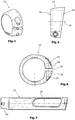
- Fig. 1
- eine schematische Ansicht des Fahrradgriffs von unten,
- Fig. 2
- eine schematische Seitenansicht des in
Fig. 1 dargestellten Fahrradgriffs, - Fig. 3
- eine schematische Schnittansicht des in
Fig. 1 dargestellten Fahrradgriffs entlang der Linie III-III, - Fig. 4
- eine schematische perspektivische Ansicht des Klemmelements,
- Fig. 5
- eine schematische Seitenansicht des Klemmelements,
- Fig. 6
- eine schematische Draufsicht des Klemmelements, und
- Fig. 7
- eine schematische Seitenansicht einer Hülse des Fahrradgriffs.
- Der in bevorzugter Ausführungsform in den Figuren dargestellte erfindungsgemäße Fahrradgriff weist eine im Wesentlichen zylindrisch ausgebildete Hülse 10 (
Fig. 7 ) auf. Dies Hülse 10 ist insbesondere aus härterem Kunststoff hergestellt und von einem Griffelement 12 umgeben, beispielsweise umspritzt. Das Griffelement 12 ist hierbei vorzugsweise aus einem weicheren Material hergestellt. Ggf. kann das Griffelement 12 auch aus unterschiedlichen Materialien hergestellt sein, so dass in einem in montiertem Zustand oberen Bereich 14 das Griffelement 12 ein anderes Material als in dem übrigen, insbesondere in dem in montiertem Zustand unteren Bereich 16 aufweist. Hierdurch kann die Griffigkeit des Fahrradgriffs und damit das Handling verbessert werden. - Die Hülse 10 im montierten Zustand unmittelbar an der Außenseite des Lenkrads an und weist vorzugsweise einen gegenüber dem Griffelement auf einer in montiertem Zustand inneren Seite vorstehenden Klemmbereich 18 (
Fig. 3 ) auf. Der Klemmbereich 18, der im dargestellten Ausführungsbeispiel einen Klemmschlitz 20 aufweist, ist von einem im dargestellten Ausführungsbeispiel als Schelle ausgebildeten Klemmelement 22 (Fig. 1 ) umgeben. Der Schlitz 20 kann sich hierbei insbesondere um einen Winkelbereich von ca. 30° des Klemmbereichs 18 erstrecken. In diesem Bereich ist in montiertem Zustand ein Vorsprung 24 des Klemmelements 22 (Fig. 6 ) angeordnet. Hierdurch ist die Positionierung des Klemmelements 22 relativ zu der Hülse 12 und somit zu dem gesamten Fahrradgriff definiert. - Ferner kann die Hülse eine oder mehrere Ausnehmungen 26 (
Fig. 7 ) aufweisen. Bei den Ausnehmungen 26 kann es sich um durchgehende Öffnungen in der Hülse 10 handeln oder auch um Vertiefungen in der Hülse 10. Die Ausnehmungen 26 bewirken, dass ein darüber angeordneter Bereich des Griffelements 12 eine geringere Unterstützung erfährt und insofern höhere Dämpfungseigenschaften realisiert sind. Die Ausnehmung 26 erstreckt sich insbesondere in einer äußeren Hälfte der Hülse 10 und ist in montiertem Zustand im Wesentlichen in Richtung des Fahrers ausgerichtet. Eine verbesserte, weichere Dämpfung erfolgt somit insbesondere im Bereich des Handtellers. Über diesen werden eine Vielzahl von Stößen in die Hand bzw. das Handgelenk des Fahrers eingeleitet. - Erfindungsgemäß ist eine Außenfläche 28 gegenüber einer Außenseite 30 eines Fahrradlenkers 32 (
Fig. 3 ) geneigt. In nicht montiertem Zustand weist die Außenfläche 28 des Griffelements 12 gegenüber einer Längsachse 34 des Fahrradgriffs einen Winkel ≠ 90° auf. Der entsprechende Winkel α zwischen der Längsachse 34 und der Außenfläche 28 beträgt etwa 100 - 125°, vorzugsweise 110 - 115°. Ein Winkel β zwischen der Außenseite 28 des Griffelements und der Außenseite 30 des Fahrradlenkers 32 liegt somit im Bereich von 10 - 15° und vorzugsweise 20 - 25°. - Die Hülse 10 ist durch einen vorzugsweise ebenfalls aus steifem Material hergestellten Stopfen oder Einsatz 29 verschlossen. Dieser ist vorzugsweise mit der Hülse bspw. durch Verkleben, Verpressen, Verschweißen oder dergleichen fest verbunden. Der Einsatz 29 trägt ein insbesondere kreisförmig ausgebildetes Einsatzelement 31, das über eine Rastverbindung 33 fixiert ist. Der insbesondere aus steifem Material hergestellte Einsatz 29 dient zur Versteifung des Fahrradgriffs in den über die Lenkeraußenseite überstehenden Bereichen. Der Einsatz 29 verschließt vorzugsweise die Außenseite der Hülse 10.
- Ein weiterer erfindungswesentlicher Aspekt besteht darin, dass ein Randbereich 36 des Griffelements 12 in montiertem Zustand seitlich über die Außenseite 30 des Fahrradlenkers 32 vorsteht (
Fig. 3 ). Hierdurch ist eine Griffverbreiterung bezogen auf den Fahrradlenker erzielt. Dies führt zu einem besseren Handling und einer insbesondere bei Fahrradgriffen für Enduro-Fahrrädern ergonomischeren Hand- und Unterarmhaltung. - Der Randbereich 36 des Griffelements 12 ist ferner verdickt. Hierzu nimmt im dargestellten Ausführungsbeispiel das aus einem anderen Material hergestellte Teil 14 des Griffelements 12, ausgehend etwa von der Mitte des Griffelements 12, nach außen in der Dicke kontinuierlich zu. Die Dickenzunahme erfolgt hierbei vorzugsweise nur an einer im montierten Zustand oberen Seite des Griffelements. Insbesondere ausgehend von der Mitte des Griffelements nach außen, ist die Dicke des Griffelements in den übrigen Bereichen, d.h. in den in Fahrtrichtung nach vorne, hinten oder unten weisenden Bereichen konstant. Das Griffelement ist somit im Wesentlichen hohl-zylindrisch ausgestaltet, mit der Ausnahme der Verdickung im Randbereich 36, der kontinuierlichen Dickenzunahme an der Oberseite und der Verdickung im Randbereich 40 der Innenseite, wobei die Verdickung an der Innenseite optional ist.
- Zur Verbesserung des Greifkomforts ist das Griffelement 12 aus Material, das eine gewisse Elastizität bzw. Weichheit aufweist und insbesondere weicher als die Hülse 10 ist. Dies gilt insbesondere auch für die Verdickungen im Randbereich 36 sowie im Randbereich 40.
- Eine im Wesentlichen der Neigung der Außenfläche entsprechende Neigung weist auch eine Innenseite 38 auf. Die Innenseite 38 verläuft im Wesentlichen parallel zur Außenfläche 28.
- Ein weiterer zur Verbesserung der Ergonomie der Handhaltung bevorzugter Aspekt der Erfindung besteht darin, dass ein innerer Randbereich 40 des Griffelements 12 ebenfalls verdickt ist. Hierbei handelt es sich um eine nur im Randbereich erfolgende Verdickung mit verhältnismäßig kleinem Radius. Im Unterschied zu der Verdickung des äußeren Randbereichs 36 beginnt diese Verdickung nur etwa 15 - 20 mm innerhalb des Griffelements 12. In montiertem Zustand ist die innere Verdickung 40 nach unten und die äußere Verdickung im Randbereich 36 nach oben ausgerichtet. An der inneren Verdickung 40 liegt somit der Daumen, und an der äußeren am Randbereich 36 vorgesehenen Verdickung der Handballen an. Hierdurch ist die Hand ergonomisch ausgerichtet.
- Das im dargestellten Ausführungsbeispiel als Schelle ausgebildete Klemmelement 22 (
Fig. 4 - 6 ) ist in Seitenansicht (Fig. 5 ) trapezförmig ausgestaltet. Eine Innenseite 42 des Klemmelements 22 ist gegenüber der Längsachse 34 des Griffelements in entgegengesetzter Richtung zu der Innenseite 38 des Griffelements 12 geneigt. In montiertem Zustand liegen die beiden Flächen 38, 42 ganzflächig aneinander an. - Die der Innenseite 42 gegenüberliegende Außenseite 44 des Klemmelements 22 ist senkrecht zu der Längsachse 34 ausgerichtet. In montiertem Zustand (
Fig. 1 ) weist dies den Vorteil auf, dass unmittelbar anschließend an das Klemmelement 22, beispielsweise Klemmelemente für die Bremse oder die Schaltung auf dem Lenker 32 angeordnet werden können. - Das Klemmelement 32 weist an seiner in Seitenansicht (
Fig. 5 ) schmaleren Seite eine Verdickung auf, in der ein Schlitz 46 ausgebildet ist. Über entsprechend ausgebildete Bohrungen 48, die ggf. ein Innengewinde aufweisen, kann ein Klemmmittel, wie eine Schraube, eingesetzt werden.
Claims (11)
- Fahrradgriff, insbesondere für Enduro-Fahrräder, mit
einer im Wesentlichen zylindrischen Hülse (10) zum Aufstecken des Fahrradgriffs auf einen Fahrradlenker (32), und
einem die Hülse (10) umgebenden Griffelement (12),
wobei die Hülse (10) einen sich an eine Innenseite (38) des Griffelements (12) anschließenden Klemmbereich (18) aufweist, der von einem Klemmelement (22) umgeben ist,
dadurch gekennzeichnet, dass
das Griffelement (12) eine Außenfläche (28) aufweist, die in montiertem Zustand zu einer Längsachse (34) des Fahrradgriffs einen Winkel ≠ 90° aufweist, wobei aufgrund der geneigten Außenfläche (28) ein äußerer Randbereich (36) des Griffelements (12) ausgebildet ist, der in montiertem Zustand des Fahrradgriffs seitlich über die Außenseite (30) des Fahrradlenkers (32) übersteht, das Griffelement im Randbereich verdickt ist, wobei der verdickte Randbereich in montiertem Zustand nach oben weist und
eine Dicke des Griffelements in einem im montierten Zustand nach oben weisenden Bereich ausgehend von etwa der Mitte des Griffelements bis zum im montierten Zustand äußeren Randbereichs zunimmt. - Fahrradgriff nach Anspruch 1, dadurch gekennzeichnet, dass die Dickenzunahme kontinuierlich und/oder stufenlos erfolgt.
- Fahrradgriff nach Anspruch 1 oder 2, dadurch gekennzeichnet, dass eine Oberseite des Griffelements im Bereich der Dickenzunahme im Wesentlichen eben ist.
- Fahrradgriff nach einem der Ansprüche 1 bis 3, dass das Griffelement (12) eine Außenfläche (28) aufweist, die in montiertem Zustand des Fahrradgriffs zu einer Außenseite (30) des Fahrradlenkers (32) geneigt ist.
- Fahrradgriff nach einem der Ansprüche 1 bis 4, dadurch gekennzeichnet, dass die Außenfläche (28) gegenüber der Längsachse (34) des Fahrradgriffs einen Winkel (α) von 100 - 125°, insbesondere 110 - 115° aufweist.
- Fahrradgriff nach einem der Ansprüche 1 - 5, dadurch gekennzeichnet, dass eine Innenseite (38) des Griffelements (12) gegenüber der Längsachse (34) des Fahrradgriffs geneigt ist, wobei die Innenseite (38) vorzugsweise im Wesentlichen parallel zur Außenfläche (28) verläuft.
- Fahrradgriff nach Anspruch 6, dadurch gekennzeichnet, dass im Bereich der Innenseite (38) ein innerer Randbereich (40) des Griffelements verdickt ist, wobei der innere Randbereich (40) in montiertem Zustand des Fahrradgriffs vorzugsweise nach unten weist.
- Fahrradgriff nach einem der Ansprüche 1 - 7, dadurch gekennzeichnet, dass der Klemmbereich (18) einen insbesondere in Längsrichtung (34) des Fahrradgriffs verlaufenden Klemmschlitz (20) aufweist.
- Fahrradgriff nach Anspruch 8, dadurch gekennzeichnet, dass das Klemmelement (22) in Seitenansicht im Wesentlichen trapezförmig ist.
- Fahrradgriff nach Anspruch 8 oder 9, dadurch gekennzeichnet, dass das Klemmelement (22) eine an der Innenseite (38) des Griffelements (12) anliegende Innenseite (42) aufweist.
- Fahrradgriff nach einem der Ansprüche 8 - 10, dadurch gekennzeichnet, dass eine Außenseite (44) des Klemmelement (22) im Wesentlichen senkrecht zur Längsachse (34) des Fahrradgriffs ausgerichtet ist.
Applications Claiming Priority (1)
| Application Number | Priority Date | Filing Date | Title |
|---|---|---|---|
| DE202013007448.5U DE202013007448U1 (de) | 2013-08-22 | 2013-08-22 | Fahrradgriff |
Publications (3)
| Publication Number | Publication Date |
|---|---|
| EP2840015A1 EP2840015A1 (de) | 2015-02-25 |
| EP2840015B1 true EP2840015B1 (de) | 2020-07-01 |
| EP2840015B2 EP2840015B2 (de) | 2025-01-22 |
Family
ID=51357862
Family Applications (1)
| Application Number | Title | Priority Date | Filing Date |
|---|---|---|---|
| EP14181612.4A Active EP2840015B2 (de) | 2013-08-22 | 2014-08-20 | Fahrradgriff |
Country Status (2)
| Country | Link |
|---|---|
| EP (1) | EP2840015B2 (de) |
| DE (2) | DE202013007448U1 (de) |
Families Citing this family (4)
| Publication number | Priority date | Publication date | Assignee | Title |
|---|---|---|---|---|
| DE202016001959U1 (de) | 2016-03-24 | 2017-06-27 | Rti Sports Gmbh | Downhill-Fahrradgriff |
| DE202017004442U1 (de) * | 2017-08-25 | 2018-11-27 | Ergon International Gmbh | Fahrradgriff |
| DE102022119624A1 (de) | 2022-08-04 | 2024-02-15 | MPR GmbH & Co. KG | Lenkergriff |
| DE102023108575A1 (de) | 2023-04-04 | 2024-10-10 | MPR GmbH & Co. KG | Fahrradgriff |
Citations (6)
| Publication number | Priority date | Publication date | Assignee | Title |
|---|---|---|---|---|
| WO1999039970A1 (de) | 1998-02-05 | 1999-08-12 | Graetz Michael | Klemmgriff, insbesondere für lenkstangen von fahrrädern und dergleichen |
| DE20303932U1 (de) * | 2003-01-09 | 2003-05-22 | International Bicycle Products Corp., Taicha, Taichung | Lenker-Handgriff für ein Fahrrad |
| DE202005013861U1 (de) | 2005-09-01 | 2007-01-11 | Rti Sports Vertrieb Von Sportartikeln Gmbh | Fahrradgriff |
| WO2011021132A1 (en) | 2009-08-19 | 2011-02-24 | Sunny Wheel Industrial Co. Ltd | Bicycle handlebar grip |
| EP2500248A1 (de) | 2011-03-15 | 2012-09-19 | Velo Enterprise Co., Ltd. | Lenkermontierter Griff |
| DE202011104764U1 (de) | 2011-08-24 | 2012-11-27 | RTI Sports, Vertrieb von Sportartikeln GmbH | Fahrradgriff |
Family Cites Families (7)
| Publication number | Priority date | Publication date | Assignee | Title |
|---|---|---|---|---|
| US445914A (en) * | 1891-02-03 | Henry waterson | ||
| BE443664A (de) * | 1941-12-09 | 1942-01-31 | ||
| DE8135796U1 (de) * | 1981-12-09 | 1982-03-11 | Gerdes Gmbh & Co, 5830 Schwelm | Griff zur befestigung auf einer insbesondere rohrfoermigen stange |
| JPH0199789U (de) * | 1987-12-25 | 1989-07-04 | ||
| CA2009728A1 (en) * | 1989-08-29 | 1991-02-28 | Yukio Nakamura | Steering handle grip for jet-propelled type gliding boats |
| ITVI20010079A1 (it) * | 2001-04-06 | 2002-10-06 | Selle Royal Spa | Manopola per manubrio in particolare di bicicletta |
| NL1026246C2 (nl) * | 2004-05-21 | 2005-11-22 | Konink Gazelle B V | Handvat. |
-
2013
- 2013-08-22 DE DE202013007448.5U patent/DE202013007448U1/de not_active Expired - Lifetime
-
2014
- 2014-08-20 EP EP14181612.4A patent/EP2840015B2/de active Active
- 2014-08-20 DE DE202014011432.3U patent/DE202014011432U1/de not_active Expired - Lifetime
Patent Citations (7)
| Publication number | Priority date | Publication date | Assignee | Title |
|---|---|---|---|---|
| WO1999039970A1 (de) | 1998-02-05 | 1999-08-12 | Graetz Michael | Klemmgriff, insbesondere für lenkstangen von fahrrädern und dergleichen |
| DE20303932U1 (de) * | 2003-01-09 | 2003-05-22 | International Bicycle Products Corp., Taicha, Taichung | Lenker-Handgriff für ein Fahrrad |
| DE202005013861U1 (de) | 2005-09-01 | 2007-01-11 | Rti Sports Vertrieb Von Sportartikeln Gmbh | Fahrradgriff |
| WO2011021132A1 (en) | 2009-08-19 | 2011-02-24 | Sunny Wheel Industrial Co. Ltd | Bicycle handlebar grip |
| EP2500248A1 (de) | 2011-03-15 | 2012-09-19 | Velo Enterprise Co., Ltd. | Lenkermontierter Griff |
| DE202011104764U1 (de) | 2011-08-24 | 2012-11-27 | RTI Sports, Vertrieb von Sportartikeln GmbH | Fahrradgriff |
| WO2013026756A1 (de) | 2011-08-24 | 2013-02-28 | Rti Sports Vertrieb Von Sportartikeln Gmbh | Fahrradgriff |
Non-Patent Citations (4)
| Title |
|---|
| ANONYMOUS: "Ride Giant", RIDE GIANT 2013 FULL LINE SOURCEBOOK, GIANT BICYCLE CANADA, INC., 1 January 2013 (2013-01-01), pages 1 - 3, XP093092830, Retrieved from the Internet <URL:https://vdocuments.mx/giant-uk-2012-brochure.html?page=130> [retrieved on 20231018] |
| CUBE: "Katalog Cube Workbook 2013", 2013, article "Griffe, RFR Griffe", XP055794167 |
| GIANT BICYCLES: "Giant - catalogue 2012", 2011, article "Grips, tape and bar ends", XP055794166 |
| ZEDLER-INSTITUT- KURY BERICHT, 3 February 2021 (2021-02-03), pages 1 - 45 |
Also Published As
| Publication number | Publication date |
|---|---|
| EP2840015A1 (de) | 2015-02-25 |
| DE202014011432U1 (de) | 2020-07-08 |
| EP2840015B2 (de) | 2025-01-22 |
| DE202013007448U1 (de) | 2014-11-25 |
Similar Documents
| Publication | Publication Date | Title |
|---|---|---|
| EP2423089B1 (de) | Fahrradgriff | |
| EP2423088B1 (de) | Fahrradgriff | |
| EP3786045A1 (de) | Rennradlenker | |
| EP3085611B1 (de) | Lenkervorbau | |
| EP2840015B2 (de) | Fahrradgriff | |
| EP3222507B1 (de) | Downhill-fahrradgriff | |
| DE202004021618U1 (de) | Fahrradgriff | |
| EP3736200B1 (de) | Lenkervorbau sowie vorbausystem | |
| EP3895965A1 (de) | Fahrradgriff | |
| EP3257734B1 (de) | Fahrradgriff | |
| EP2748056B1 (de) | Fahrradgriff | |
| EP3390212B1 (de) | Fahrradlenker | |
| DE202007012180U1 (de) | Fahrradgriff | |
| EP2881314B1 (de) | Fahrradgriff | |
| DE102018212198A1 (de) | Fahrradgriff | |
| DE202009005939U1 (de) | Griff mit Nut und Haltering | |
| EP3279071B1 (de) | Griffelement | |
| EP2431268A1 (de) | Fahrrad-Lenkergriff | |
| DE202005013861U1 (de) | Fahrradgriff | |
| EP3590803A1 (de) | Fahrradsattel | |
| EP4477516A1 (de) | Fahrradgriff | |
| EP3786047B1 (de) | Fahrradgriff mit asymmetrischer innenhülse | |
| EP4727830A1 (de) | Fahrradgriff | |
| DE102020119618A1 (de) | Griff für den Lenker eines Zweirads | |
| DE202021104464U1 (de) | Handgriff mit Verdrehsicherung, Griffanordnung sowie Rollator aufweisend selbige |
Legal Events
| Date | Code | Title | Description |
|---|---|---|---|
| PUAI | Public reference made under article 153(3) epc to a published international application that has entered the european phase |
Free format text: ORIGINAL CODE: 0009012 |
|
| 17P | Request for examination filed |
Effective date: 20140820 |
|
| AK | Designated contracting states |
Kind code of ref document: A1 Designated state(s): AL AT BE BG CH CY CZ DE DK EE ES FI FR GB GR HR HU IE IS IT LI LT LU LV MC MK MT NL NO PL PT RO RS SE SI SK SM TR |
|
| AX | Request for extension of the european patent |
Extension state: BA ME |
|
| R17P | Request for examination filed (corrected) |
Effective date: 20150824 |
|
| RBV | Designated contracting states (corrected) |
Designated state(s): AL AT BE BG CH CY CZ DE DK EE ES FI FR GB GR HR HU IE IS IT LI LT LU LV MC MK MT NL NO PL PT RO RS SE SI SK SM TR |
|
| RAP1 | Party data changed (applicant data changed or rights of an application transferred) |
Owner name: RTI SPORTS GMBH |
|
| STAA | Information on the status of an ep patent application or granted ep patent |
Free format text: STATUS: EXAMINATION IS IN PROGRESS |
|
| 17Q | First examination report despatched |
Effective date: 20170407 |
|
| RAP1 | Party data changed (applicant data changed or rights of an application transferred) |
Owner name: ERGON INTERNATIONAL GMBH |
|
| GRAP | Despatch of communication of intention to grant a patent |
Free format text: ORIGINAL CODE: EPIDOSNIGR1 |
|
| STAA | Information on the status of an ep patent application or granted ep patent |
Free format text: STATUS: GRANT OF PATENT IS INTENDED |
|
| INTG | Intention to grant announced |
Effective date: 20200117 |
|
| GRAS | Grant fee paid |
Free format text: ORIGINAL CODE: EPIDOSNIGR3 |
|
| GRAA | (expected) grant |
Free format text: ORIGINAL CODE: 0009210 |
|
| STAA | Information on the status of an ep patent application or granted ep patent |
Free format text: STATUS: THE PATENT HAS BEEN GRANTED |
|
| AK | Designated contracting states |
Kind code of ref document: B1 Designated state(s): AL AT BE BG CH CY CZ DE DK EE ES FI FR GB GR HR HU IE IS IT LI LT LU LV MC MK MT NL NO PL PT RO RS SE SI SK SM TR |
|
| REG | Reference to a national code |
Ref country code: CH Ref legal event code: EP Ref country code: AT Ref legal event code: REF Ref document number: 1285928 Country of ref document: AT Kind code of ref document: T Effective date: 20200715 |
|
| REG | Reference to a national code |
Ref country code: DE Ref legal event code: R096 Ref document number: 502014014383 Country of ref document: DE |
|
| REG | Reference to a national code |
Ref country code: IE Ref legal event code: FG4D Free format text: LANGUAGE OF EP DOCUMENT: GERMAN |
|
| REG | Reference to a national code |
Ref country code: NL Ref legal event code: FP |
|
| PGFP | Annual fee paid to national office [announced via postgrant information from national office to epo] |
Ref country code: NL Payment date: 20200916 Year of fee payment: 7 |
|
| REG | Reference to a national code |
Ref country code: LT Ref legal event code: MG4D |
|
| PG25 | Lapsed in a contracting state [announced via postgrant information from national office to epo] |
Ref country code: BG Free format text: LAPSE BECAUSE OF FAILURE TO SUBMIT A TRANSLATION OF THE DESCRIPTION OR TO PAY THE FEE WITHIN THE PRESCRIBED TIME-LIMIT Effective date: 20201001 |
|
| PGFP | Annual fee paid to national office [announced via postgrant information from national office to epo] |
Ref country code: BE Payment date: 20200909 Year of fee payment: 7 |
|
| PG25 | Lapsed in a contracting state [announced via postgrant information from national office to epo] |
Ref country code: FI Free format text: LAPSE BECAUSE OF FAILURE TO SUBMIT A TRANSLATION OF THE DESCRIPTION OR TO PAY THE FEE WITHIN THE PRESCRIBED TIME-LIMIT Effective date: 20200701 Ref country code: LT Free format text: LAPSE BECAUSE OF FAILURE TO SUBMIT A TRANSLATION OF THE DESCRIPTION OR TO PAY THE FEE WITHIN THE PRESCRIBED TIME-LIMIT Effective date: 20200701 Ref country code: CZ Free format text: LAPSE BECAUSE OF FAILURE TO SUBMIT A TRANSLATION OF THE DESCRIPTION OR TO PAY THE FEE WITHIN THE PRESCRIBED TIME-LIMIT Effective date: 20200701 Ref country code: PT Free format text: LAPSE BECAUSE OF FAILURE TO SUBMIT A TRANSLATION OF THE DESCRIPTION OR TO PAY THE FEE WITHIN THE PRESCRIBED TIME-LIMIT Effective date: 20201102 Ref country code: GR Free format text: LAPSE BECAUSE OF FAILURE TO SUBMIT A TRANSLATION OF THE DESCRIPTION OR TO PAY THE FEE WITHIN THE PRESCRIBED TIME-LIMIT Effective date: 20201002 Ref country code: ES Free format text: LAPSE BECAUSE OF FAILURE TO SUBMIT A TRANSLATION OF THE DESCRIPTION OR TO PAY THE FEE WITHIN THE PRESCRIBED TIME-LIMIT Effective date: 20200701 Ref country code: NO Free format text: LAPSE BECAUSE OF FAILURE TO SUBMIT A TRANSLATION OF THE DESCRIPTION OR TO PAY THE FEE WITHIN THE PRESCRIBED TIME-LIMIT Effective date: 20201001 Ref country code: HR Free format text: LAPSE BECAUSE OF FAILURE TO SUBMIT A TRANSLATION OF THE DESCRIPTION OR TO PAY THE FEE WITHIN THE PRESCRIBED TIME-LIMIT Effective date: 20200701 Ref country code: SE Free format text: LAPSE BECAUSE OF FAILURE TO SUBMIT A TRANSLATION OF THE DESCRIPTION OR TO PAY THE FEE WITHIN THE PRESCRIBED TIME-LIMIT Effective date: 20200701 |
|
| PG25 | Lapsed in a contracting state [announced via postgrant information from national office to epo] |
Ref country code: RS Free format text: LAPSE BECAUSE OF FAILURE TO SUBMIT A TRANSLATION OF THE DESCRIPTION OR TO PAY THE FEE WITHIN THE PRESCRIBED TIME-LIMIT Effective date: 20200701 Ref country code: LV Free format text: LAPSE BECAUSE OF FAILURE TO SUBMIT A TRANSLATION OF THE DESCRIPTION OR TO PAY THE FEE WITHIN THE PRESCRIBED TIME-LIMIT Effective date: 20200701 Ref country code: PL Free format text: LAPSE BECAUSE OF FAILURE TO SUBMIT A TRANSLATION OF THE DESCRIPTION OR TO PAY THE FEE WITHIN THE PRESCRIBED TIME-LIMIT Effective date: 20200701 Ref country code: IS Free format text: LAPSE BECAUSE OF FAILURE TO SUBMIT A TRANSLATION OF THE DESCRIPTION OR TO PAY THE FEE WITHIN THE PRESCRIBED TIME-LIMIT Effective date: 20201101 |
|
| REG | Reference to a national code |
Ref country code: DE Ref legal event code: R026 Ref document number: 502014014383 Country of ref document: DE |
|
| PG25 | Lapsed in a contracting state [announced via postgrant information from national office to epo] |
Ref country code: MC Free format text: LAPSE BECAUSE OF FAILURE TO SUBMIT A TRANSLATION OF THE DESCRIPTION OR TO PAY THE FEE WITHIN THE PRESCRIBED TIME-LIMIT Effective date: 20200701 |
|
| REG | Reference to a national code |
Ref country code: CH Ref legal event code: PL |
|
| PLBI | Opposition filed |
Free format text: ORIGINAL CODE: 0009260 |
|
| PLAX | Notice of opposition and request to file observation + time limit sent |
Free format text: ORIGINAL CODE: EPIDOSNOBS2 |
|
| PG25 | Lapsed in a contracting state [announced via postgrant information from national office to epo] |
Ref country code: LU Free format text: LAPSE BECAUSE OF NON-PAYMENT OF DUE FEES Effective date: 20200820 Ref country code: RO Free format text: LAPSE BECAUSE OF FAILURE TO SUBMIT A TRANSLATION OF THE DESCRIPTION OR TO PAY THE FEE WITHIN THE PRESCRIBED TIME-LIMIT Effective date: 20200701 Ref country code: SM Free format text: LAPSE BECAUSE OF FAILURE TO SUBMIT A TRANSLATION OF THE DESCRIPTION OR TO PAY THE FEE WITHIN THE PRESCRIBED TIME-LIMIT Effective date: 20200701 Ref country code: EE Free format text: LAPSE BECAUSE OF FAILURE TO SUBMIT A TRANSLATION OF THE DESCRIPTION OR TO PAY THE FEE WITHIN THE PRESCRIBED TIME-LIMIT Effective date: 20200701 Ref country code: DK Free format text: LAPSE BECAUSE OF FAILURE TO SUBMIT A TRANSLATION OF THE DESCRIPTION OR TO PAY THE FEE WITHIN THE PRESCRIBED TIME-LIMIT Effective date: 20200701 Ref country code: CH Free format text: LAPSE BECAUSE OF NON-PAYMENT OF DUE FEES Effective date: 20200831 Ref country code: IT Free format text: LAPSE BECAUSE OF FAILURE TO SUBMIT A TRANSLATION OF THE DESCRIPTION OR TO PAY THE FEE WITHIN THE PRESCRIBED TIME-LIMIT Effective date: 20200701 Ref country code: LI Free format text: LAPSE BECAUSE OF NON-PAYMENT OF DUE FEES Effective date: 20200831 |
|
| 26 | Opposition filed |
Opponent name: MPR GMBH & CO. KG Effective date: 20210326 |
|
| PG25 | Lapsed in a contracting state [announced via postgrant information from national office to epo] |
Ref country code: AL Free format text: LAPSE BECAUSE OF FAILURE TO SUBMIT A TRANSLATION OF THE DESCRIPTION OR TO PAY THE FEE WITHIN THE PRESCRIBED TIME-LIMIT Effective date: 20200701 |
|
| PG25 | Lapsed in a contracting state [announced via postgrant information from national office to epo] |
Ref country code: SK Free format text: LAPSE BECAUSE OF FAILURE TO SUBMIT A TRANSLATION OF THE DESCRIPTION OR TO PAY THE FEE WITHIN THE PRESCRIBED TIME-LIMIT Effective date: 20200701 |
|
| PG25 | Lapsed in a contracting state [announced via postgrant information from national office to epo] |
Ref country code: FR Free format text: LAPSE BECAUSE OF NON-PAYMENT OF DUE FEES Effective date: 20200901 |
|
| PLBB | Reply of patent proprietor to notice(s) of opposition received |
Free format text: ORIGINAL CODE: EPIDOSNOBS3 |
|
| PG25 | Lapsed in a contracting state [announced via postgrant information from national office to epo] |
Ref country code: IE Free format text: LAPSE BECAUSE OF NON-PAYMENT OF DUE FEES Effective date: 20200820 Ref country code: SI Free format text: LAPSE BECAUSE OF FAILURE TO SUBMIT A TRANSLATION OF THE DESCRIPTION OR TO PAY THE FEE WITHIN THE PRESCRIBED TIME-LIMIT Effective date: 20200701 |
|
| REG | Reference to a national code |
Ref country code: AT Ref legal event code: MM01 Ref document number: 1285928 Country of ref document: AT Kind code of ref document: T Effective date: 20200820 |
|
| PG25 | Lapsed in a contracting state [announced via postgrant information from national office to epo] |
Ref country code: AT Free format text: LAPSE BECAUSE OF NON-PAYMENT OF DUE FEES Effective date: 20200820 |
|
| PGFP | Annual fee paid to national office [announced via postgrant information from national office to epo] |
Ref country code: GB Payment date: 20210824 Year of fee payment: 8 |
|
| REG | Reference to a national code |
Ref country code: NL Ref legal event code: MM Effective date: 20210901 |
|
| REG | Reference to a national code |
Ref country code: BE Ref legal event code: MM Effective date: 20210831 |
|
| PG25 | Lapsed in a contracting state [announced via postgrant information from national office to epo] |
Ref country code: TR Free format text: LAPSE BECAUSE OF FAILURE TO SUBMIT A TRANSLATION OF THE DESCRIPTION OR TO PAY THE FEE WITHIN THE PRESCRIBED TIME-LIMIT Effective date: 20200701 Ref country code: MT Free format text: LAPSE BECAUSE OF FAILURE TO SUBMIT A TRANSLATION OF THE DESCRIPTION OR TO PAY THE FEE WITHIN THE PRESCRIBED TIME-LIMIT Effective date: 20200701 Ref country code: CY Free format text: LAPSE BECAUSE OF FAILURE TO SUBMIT A TRANSLATION OF THE DESCRIPTION OR TO PAY THE FEE WITHIN THE PRESCRIBED TIME-LIMIT Effective date: 20200701 |
|
| PG25 | Lapsed in a contracting state [announced via postgrant information from national office to epo] |
Ref country code: NL Free format text: LAPSE BECAUSE OF NON-PAYMENT OF DUE FEES Effective date: 20210901 Ref country code: MK Free format text: LAPSE BECAUSE OF FAILURE TO SUBMIT A TRANSLATION OF THE DESCRIPTION OR TO PAY THE FEE WITHIN THE PRESCRIBED TIME-LIMIT Effective date: 20200701 |
|
| PG25 | Lapsed in a contracting state [announced via postgrant information from national office to epo] |
Ref country code: BE Free format text: LAPSE BECAUSE OF NON-PAYMENT OF DUE FEES Effective date: 20210831 |
|
| GBPC | Gb: european patent ceased through non-payment of renewal fee |
Effective date: 20220820 |
|
| P01 | Opt-out of the competence of the unified patent court (upc) registered |
Effective date: 20230523 |
|
| PG25 | Lapsed in a contracting state [announced via postgrant information from national office to epo] |
Ref country code: GB Free format text: LAPSE BECAUSE OF NON-PAYMENT OF DUE FEES Effective date: 20220820 |
|
| PUAH | Patent maintained in amended form |
Free format text: ORIGINAL CODE: 0009272 |
|
| STAA | Information on the status of an ep patent application or granted ep patent |
Free format text: STATUS: PATENT MAINTAINED AS AMENDED |
|
| 27A | Patent maintained in amended form |
Effective date: 20250122 |
|
| AK | Designated contracting states |
Kind code of ref document: B2 Designated state(s): AL AT BE BG CH CY CZ DE DK EE ES FI FR GB GR HR HU IE IS IT LI LT LU LV MC MK MT NL NO PL PT RO RS SE SI SK SM TR |
|
| REG | Reference to a national code |
Ref country code: DE Ref legal event code: R102 Ref document number: 502014014383 Country of ref document: DE |
|
| PGFP | Annual fee paid to national office [announced via postgrant information from national office to epo] |
Ref country code: DE Payment date: 20250729 Year of fee payment: 12 |