EP2839903A1 - Cooling apparatus and segment for continuous casting machine provided with same - Google Patents
Cooling apparatus and segment for continuous casting machine provided with same Download PDFInfo
- Publication number
- EP2839903A1 EP2839903A1 EP20120874530 EP12874530A EP2839903A1 EP 2839903 A1 EP2839903 A1 EP 2839903A1 EP 20120874530 EP20120874530 EP 20120874530 EP 12874530 A EP12874530 A EP 12874530A EP 2839903 A1 EP2839903 A1 EP 2839903A1
- Authority
- EP
- European Patent Office
- Prior art keywords
- unit
- rod
- coolant
- cooling apparatus
- coolant spray
- Prior art date
- Legal status (The legal status is an assumption and is not a legal conclusion. Google has not performed a legal analysis and makes no representation as to the accuracy of the status listed.)
- Granted
Links
Images


Classifications
-
- B—PERFORMING OPERATIONS; TRANSPORTING
- B22—CASTING; POWDER METALLURGY
- B22D—CASTING OF METALS; CASTING OF OTHER SUBSTANCES BY THE SAME PROCESSES OR DEVICES
- B22D11/00—Continuous casting of metals, i.e. casting in indefinite lengths
- B22D11/12—Accessories for subsequent treating or working cast stock in situ
- B22D11/124—Accessories for subsequent treating or working cast stock in situ for cooling
-
- B—PERFORMING OPERATIONS; TRANSPORTING
- B22—CASTING; POWDER METALLURGY
- B22D—CASTING OF METALS; CASTING OF OTHER SUBSTANCES BY THE SAME PROCESSES OR DEVICES
- B22D11/00—Continuous casting of metals, i.e. casting in indefinite lengths
- B22D11/12—Accessories for subsequent treating or working cast stock in situ
- B22D11/124—Accessories for subsequent treating or working cast stock in situ for cooling
- B22D11/1246—Nozzles; Spray heads
Definitions
- the present invention relates to a cooling apparatus and a segment for a continuous casting machine having the same, and more particularly, to a cooling apparatus that is capable of effectively cooling a strand in response to a variation in width of the strand when continuous casting is performed and a segment for a continuous casting machine having the cooling apparatus.
- molten steel is continuously injected into a mold having a predetermined shape, and then a strand that is semi-coagulated in the mold is continuously drawn downward from the mold to manufacture half-finished products having various shapes such as slabs, blooms, and billets.
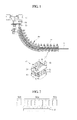
- FIG. 1 A schematic configuration of the general continuous casting apparatus in which the above-described continuous casting process is performed and a segment provided in the continuous casting machine will now be described with reference to FIG. 1 .
- a general continuous casting machine includes a ladle 10 into which molten steel refined through a steel manufacturing process is received, a tundish 20 receiving the molten steel through an injection nozzle connected to the ladle 10 to temporarily store the molten steel, a mold 30 receiving the molten steel temporarily stored in the tundish 20 to initially coagulate the received molten steel in a predetermined shape, and a cooling line 40 disposed below the mold 30 so that a plurality of segments 50 are successively arranged on the cooling line 40 to conduct a series of molding works while performing a cooling process on a non-coagulated strand S.
- each of the segments 50 includes a plurality of tie rods (not shown) vertically connecting upper and lower frames, which are vertically spaced apart from each other, to each other so that a plurality of rollers that are respectively provided in the upper and lower frames are arranged to face each other, a plurality of hydraulic cylinders 55 using the tie rod as a piston to adjust a distance between the upper frame 51 and the lower frame 53, thereby applying a rolling force to the strand S, and a cooling apparatus (not shown) disposed in the upper and lower frames 51 and 53 to cool the strand S.
- the strand S passing through the mold 30 may be pressed by the plurality of rollers 52 and 54 while passing through the space between the upper and lower frames 51 and 53 and be molded in a predetermined shape.
- the cooling apparatus may spray coolant onto the strand S passing through the space between the upper and lower frames 51 and 53 to cool the strand S.
- the cooling apparatus has to be maintained at the same level of cooling performance regardless of a variation in width of the strand S from a narrow width to a wide width of the strand S so as to respond to the variation in width of the strand S.
- a plurality of nozzles 56a and 56b are arranged in a width direction of the strand S to cool the strand S while opening/closing a portion of nozzles, e.g., the nozzle 56b disposed on an edge of the strand S according to the width of the strand S.
- a method in which coolant is sprayed while a nozzle having a wide spray angle moves along a width of a strand has been suggested.
- the driving unit since a driving unit for moving the nozzle is disposed close to the strand S, the driving unit is deteriorated or frequently broken down due to heat generated from the strand S and moisture generated from the coolant.
- the present invention provides a cooling apparatus that is capable of easily adjusting an area on which coolant is sprayed in response to a variation in width of a strand and a segment for a continuous casting machine having the same.
- the present invention provides a precisely and stably controllable cooling apparatus and a segment for a continuous casting machine having the same.
- the present invention provides a cooling apparatus having improved durability and a segment for a continuous casting machine having the same.
- the present invention provides a cooling apparatus having improved process efficiency and productivity and a segment for a continuous casting machine having the same.
- a cooling apparatus includes: a driving unit providing a rotation force; coolant spray units respectively disposed on both sides of the driving unit, each of the coolant spray units having at least one nozzle through which coolant is sprayed; and a moving unit disposed between the driving unit and the coolant spray unit to symmetrically move the coolant spray units.
- the coolant spray unit may include: a head in which a flow passage is defined therein; and a plurality of nozzles spaced apart from each other on the head to communicate with the flow passage.
- the moving unit may move the coolant spray unit in vertical and horizontal directions and may include: a rotation shaft connected to the driving unit; a rod having one side connected to the coolant spray unit, the rod being inclinedly disposed; and a motion conversion unit disposed between the rotation shaft and the rod to convert a rotation motion into a linear motion, thereby linearly moving the rod.
- the rotation shaft and the motion conversion unit may constitute a worm gear, and the motion conversion unit and the rod may constitute a rack gear.
- the moving unit may be accommodated in a housing and fixed to the driving unit and the coolant spray unit.
- the rod having the other side on which a hallow guide member having an inner space to allow the rod to move therethrough may be disposed, wherein the guide member is fixed to the housing.
- the driving unit may include a servomotor.
- a segment for a continuous casting machine includes: upper and lower frames vertically spaced apart from each other; a plurality of rollers respectively disposed in the upper and lower frames, the plurality of rollers being arranged in a width direction of a strand; a cooling apparatus spraying coolant between the plurality of rollers; a driving unit disposed in an upper central portion of each of the upper frame and the lower frame; coolant spray units respectively disposed on both sides of the driving unit, each of the coolant spray units having at least one nozzle through which the coolant is sprayed; and a moving unit disposed between the driving unit and the coolant spray unit to symmetrically move the coolant spray units.
- the coolant spray unit having a flow passage defined therein may include: a head disposed in a longitudinal direction of the strand; and a plurality of nozzles spaced apart from each other on the head to communicate with the flow passage.
- the moving unit may reciprocate the coolant spray unit in width and vertical directions of the strand.
- the moving unit may include: a rotation shaft connected to the driving unit; a rod having one side connected to the coolant spray unit, the rod being disposed inclined toward the inside of the segment; and a motion conversion unit disposed between the rotation shaft and the rod to convert a rotation motion of the rotation shaft into a linear motion to diagonally move the rod.
- the driving unit may include a servomotor.
- the cooling apparatus and the segment for the continuous casting machine having the cooling apparatus may easily control the area onto which the coolant is sprayed in response to a variation in width of the strip that is continuously casted.
- the area onto which the coolant is sprayed may be controlled to be bilateral symmetrically distributed by using one driving unit.
- the equipment may be reduced in size and improved in maintainability to improve process efficiency and productivity and reduce manufacturing and maintenance costs.
- FIG. 3 is a view illustrating a structure of a segment for a continuous casting machine according to an embodiment of the present invention
- FIGS. 4 and 5 are a perspective view and front view of a cooling apparatus of FIG. 3 .
- a segment includes an upper roller coupling body and a lower roller coupling body.
- the segment includes an upper frame 100 and a lower frame 102, which are vertically spaced apart from each other, a plurality of girder plates 110 disposed in the upper and lower frames 100 and 102 to support a plurality of rollers disposed in a width direction of a strand S, respectively, and a cooling apparatus spraying coolant between the plurality of rollers 120 and 122.
- the segment includes a tie rod 140 through which the upper frame 100 and the lower frame 102 are vertically connected to each other in a state where the upper frame 100 are spaced apart from the lower frame and a hydraulic cylinder 130 adjusting a distance between the upper frame 100 and the lower frame 102 to apply a pressure to the strand S.
- the cooling apparatus may be disposed at each of upper central portions of the upper frame 100 and the lower frame 102, i.e., on each of the girder plates 10 to spray the coolant onto the strand S transferred between the upper frame 100 and the lower frame 102.
- the cooling apparatus includes a driving unit 210 providing a rotation force to each of the girder plates 110, first and second coolant spray units 220 and 220' disposed on both sides of the driving unit 110 and each of which includes at least one nozzle 224 through which the coolant is sprayed, first and second moving units respectively connecting the first and second coolant spray units 220 and 220' to the driving unit 210 to reciprocate the first and second coolant spray units 220 and 220' in a diagonal direction, and a control unit controlling an operation of the driving unit 210.
- a coolant injection hole through which the coolant is supplied may be defined in each of the first and second coolant spray units 220 and 220'.
- Each of the first and second coolant spray units 220 and 220' includes a head 222 having a flow passage through which the coolant flows and a plurality of nozzles 224 communicating with the flow passage and disposed spaced apart from each other on the head 222 in a longitudinal direction of the strand S.
- the plurality of nozzles 224 may be connected to the head to spray the coolant in the longitudinal direction of the strand S within the segment.
- the nozzle 224 disposed in the upper frame 100 may extend downward to spray the coolant downward, and the nozzle 224 disposed in the lower frame 102 may extend upward to spray the coolant upward.
- the plurality of nozzles 224 may spray the coolant onto the strand S passing between the upper frame 100 and the lower frame 102.
- each of the nozzles 224 may have a slit shape so that an area on which the coolant is sprayed is defined in the width direction of the strand S.
- equipment such as a pipe for supplying the coolant may be simply designed when compared to the conventional structure in which the coolant is supplied into each of the plurality of nozzles 224.
- Various kinds of motors such as a DC motor, a stepping motor, and an AC servomotor, which are capable of rotating each of rotation shafts 232, may be used as the driving unit 210.
- the driving unit 210 may be finely adjusted in rotation rate, and thus the moving distances of the coolant spray units 220 and 220' may be precisely controlled.
- one driving unit 210 that is finely adjustable in rotation rate may be used to control the moving distance of each of the pair of coolant spray units 220 and 220' that is symmetrically connected to the driving unit 210.
- the pair of coolant spray units 220 and 220' may symmetrically move in the same distance by the one driving unit 210. Also, since the driving unit 210 is disposed in the segment, the pipe for supplying the coolant into the coolant spray units 220 and 220' may be reduced in length. Thus, the equipment may be simplified in design, and a space in which the driving unit 210 is installed may be reduced in volume.
- Each of the first and second moving units includes the rotation shaft 232 connected to the driving unit 210, a rod 236 connected to the head, and a motion conversion unit disposed between the rotation shaft 232 and the rod 236.
- the first and second moving units 230 are accommodated within the housing 240 having an inner space and fixed to the driving unit 210 and the first and second coolant spray units 220 and 220'.
- the rotation shaft 232 may be horizontally connected to the driving unit 210.
- a screw may be formed along an outer circumferential surface of the rotation shaft 232.
- the screws may be formed on the rotation shafts connected to the first and second driving 210 in directions opposite to each other to symmetrically move the first and second coolant spray units 220 and 220'. That is, since the first and second coolant spray units 220 and 220' are driven by using one driving unit 210, the screws may be formed on the rotation shafts 232 connected to the driving unit 210 in the opposite directions to symmetrically move the first and second coolant spray units 220 and 220' disposed in directions opposite to each other.
- the rod 236 may be disposed on the same line in a vertical direction as the rotation shaft 232 and have one side connected to the head 222. Also, the rod 236 may be provided so that the other side of the rod 236 is inclined toward a central portion of the segment in a state where the rod 236 is connected to the head. A plurality of rods 236 may be connected to the head to sufficiently support the coolant spray units 220 and 220'. A sawtooth may be formed on an outer circumferential surface of the rod 236 along a longitudinal direction.
- the motion conversion unit may have an annular shape.
- the motion conversion unit includes a wheel 234 having a sawtooth engaged with screw of the rotation shaft 232 and the sawtooth of the rod 236 on an outer circumferential surface thereof and a shaft 234 used as a rotation shaft.
- the motion conversion unit may convert a rotation motion of the rotation shaft 232 into a linear motion to transmit the linear motion to the rod 236.
- the rod 236 may linearly move by using a rotation force supplied from the driving unit 210.
- the shaft 234 may be arranged perpendicular to the rotation shaft 232 and rotatably fixed to the inside of the housing 240.
- a worm gear may be constituted by the rotation shaft 232 and the motion conversion unit.
- the motion conversion unit and the rod 236 may constitute a rack gear. Through a combination of the worm gear and the rack gear, the rod 236 may linearly move in a diagonal direction to reciprocate the first and second coolant spray units 220 and 220' in width and vertical directions of the strand S.
- the screw formed on the rotation shaft 232 and the sawtooth formed on each of the rod 236 and the motion conversion unit may be formed so that the first and second coolant spray units 220 and 220' move by the same distance using the rotation force supplied from the driving unit 210.
- a protection member 237 that is extendable and contractible may be disposed on an outer circumferential surface of one side of the rod 236 exposed from the housing 240.
- the protection member 237 may be fixed to the housing 240.
- the protection member 237 may extend and contract according to the movement of the rod 236 and may prevent the rod 236 from being deteriorated due to high-temperature heat and moisture.
- the protection member 237 may relieve a shock generated while the rod 236 moves to prevent a connection portion between the coolant spray units 220 and 220' and the rod 236 from being damaged.
- a guide member 238 is disposed on the other side of the rod 236.
- the guide member 238 may have a hollow cylindrical shape with one side opened.
- the rod 236 may be reciprocated within the guide member 238.
- the guide member 238 may be disposed inclined toward the central portion of the segment according to the arrangement of the rod 236 and be fixed to the housing 240.
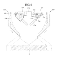
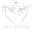
- FIGS. 6 and 7 are views illustrating a state where the cooling apparatus is in use according to an embodiment of the present invention.
- the cooling apparatus is installed in the upper roller coupling body
- the upper and lower cooling apparatus may have the same driving principle even though the upper and lower cooling apparatus may ascend or descend in directions opposite to each other.
- the rotation shaft 232 connected to the driving unit 210 rotates in one direction.
- the motion conversion unit engaged with the rotation shaft 232 rotates, and the rod 236 engaged with the motion conversion unit moves to the guide member 238 by the rotation of the motion conversion unit.
- the coolant spray units 220 and 220' connected to the rod 236 may diagonally move toward the inside of the segment to descend toward the strand S.
- the coolant spray units 220 and 220' respectively connected to both sides of the driving unit 210 may symmetrically move in the same distance.
- the nozzles 224 and 224' constituting the coolant spray units 220 and 220' and a surface of the strand S may be reduced in distance therebetween. Also, an area on which the coolant is sprayed through the nozzles 224 and 224' may be reduced.
- the strand S When a strand S having a large width, for example, a strand S having a width of approximately 700 mm is manufactured through the continuous casting process, the strand S may be cooled through a process for reversing the process for cooling the strand S having the relatively small width.
- the driving unit 210 operates through the control of the control unit to rotate the rotation shaft 232 connected to the driving unit 210 in a direction opposite to that in which the rotation shaft 232 rotates when the strand S having the small width is manufactured.
- the motion conversion unit engaged with the rotation shaft 232 rotates in a direction corresponding to that in which the rotation shaft 232 rotates, and the rod 236 engaged with the motion conversion unit moves to the outside of the guide member 238 by the rotation of the motion conversion unit.
- the coolant spray units 220 and 220' connected to the rod 236 may diagonally move toward the outside of the segment to ascend from the surface of the strand S.
- a distance between the nozzles 224 and 224' constituting the coolant spray units 220 and 220' and a surface of the strand S may increase.
- an area on which the coolant is sprayed through the nozzles 224 and 224' may increase.
- cooling apparatus has been described in regard to a cooling apparatus disposed in the segment constituting the continuous casting machine, the technical ideas of the cooling apparatus are not limited thereto.
- the cooling apparatus and the segment for continuous casting machine having the cooling apparatus may easily control the area on which the coolant is sprayed in response to a variation in width of the strand that is continuously casted using one driving unit.
- the equipment having the cooling apparatus and the segment may be significantly reduced in size when compared to that of the related art to improve the maintainability, the process efficiency, and the productivity. Therefore, the cooling apparatus and the segment for the continuous casting machine having the cooling apparatus may increase in industrial applicability.
Landscapes
- Engineering & Computer Science (AREA)
- Mechanical Engineering (AREA)
- Continuous Casting (AREA)
- Nozzles (AREA)
Abstract
Description
- The present invention relates to a cooling apparatus and a segment for a continuous casting machine having the same, and more particularly, to a cooling apparatus that is capable of effectively cooling a strand in response to a variation in width of the strand when continuous casting is performed and a segment for a continuous casting machine having the cooling apparatus.
- Generally, in a continuous casting process, molten steel is continuously injected into a mold having a predetermined shape, and then a strand that is semi-coagulated in the mold is continuously drawn downward from the mold to manufacture half-finished products having various shapes such as slabs, blooms, and billets.
- A schematic configuration of the general continuous casting apparatus in which the above-described continuous casting process is performed and a segment provided in the continuous casting machine will now be described with reference to
FIG. 1 . - A general continuous casting machine includes a
ladle 10 into which molten steel refined through a steel manufacturing process is received, a tundish 20 receiving the molten steel through an injection nozzle connected to theladle 10 to temporarily store the molten steel, amold 30 receiving the molten steel temporarily stored in the tundish 20 to initially coagulate the received molten steel in a predetermined shape, and acooling line 40 disposed below themold 30 so that a plurality ofsegments 50 are successively arranged on thecooling line 40 to conduct a series of molding works while performing a cooling process on a non-coagulated strand S. Here, each of thesegments 50 includes a plurality of tie rods (not shown) vertically connecting upper and lower frames, which are vertically spaced apart from each other, to each other so that a plurality of rollers that are respectively provided in the upper and lower frames are arranged to face each other, a plurality ofhydraulic cylinders 55 using the tie rod as a piston to adjust a distance between theupper frame 51 and thelower frame 53, thereby applying a rolling force to the strand S, and a cooling apparatus (not shown) disposed in the upper andlower frames - The strand S passing through the
mold 30 may be pressed by the plurality ofrollers lower frames lower frames FIG. 2 , a plurality ofnozzles nozzle 56b disposed on an edge of the strand S according to the width of the strand S. However, in the above-described method, since the number of nozzles increases, equipment such as a pipe may be complicated in design, and thus the cooling apparatus is difficult in maintenance. Therefore, a method in which coolant is sprayed while a nozzle having a wide spray angle moves along a width of a strand has been suggested. However, in this method, since a driving unit for moving the nozzle is disposed close to the strand S, the driving unit is deteriorated or frequently broken down due to heat generated from the strand S and moisture generated from the coolant. - Thus, in order to restrain the damage due to the heat and moisture, a method in which the driving unit is disposed outside the segment has been suggested. However, in this method, since a distance between the nozzle and the driving unit increases, it may be difficult to precisely control the movement of the nozzle. Also, since the nozzle increases in length, the nozzle may be oscillated due to a pressure of the coolant and be easily damaged.
- The present invention provides a cooling apparatus that is capable of easily adjusting an area on which coolant is sprayed in response to a variation in width of a strand and a segment for a continuous casting machine having the same.
- The present invention provides a precisely and stably controllable cooling apparatus and a segment for a continuous casting machine having the same.
- The present invention provides a cooling apparatus having improved durability and a segment for a continuous casting machine having the same.
- The present invention provides a cooling apparatus having improved process efficiency and productivity and a segment for a continuous casting machine having the same.
- A cooling apparatus according to embodiments of the present invention includes: a driving unit providing a rotation force; coolant spray units respectively disposed on both sides of the driving unit, each of the coolant spray units having at least one nozzle through which coolant is sprayed; and a moving unit disposed between the driving unit and the coolant spray unit to symmetrically move the coolant spray units.
- The coolant spray unit may include: a head in which a flow passage is defined therein; and a plurality of nozzles spaced apart from each other on the head to communicate with the flow passage.
- The moving unit may move the coolant spray unit in vertical and horizontal directions and may include: a rotation shaft connected to the driving unit; a rod having one side connected to the coolant spray unit, the rod being inclinedly disposed; and a motion conversion unit disposed between the rotation shaft and the rod to convert a rotation motion into a linear motion, thereby linearly moving the rod.
- The rotation shaft and the motion conversion unit may constitute a worm gear, and the motion conversion unit and the rod may constitute a rack gear.
- The moving unit may be accommodated in a housing and fixed to the driving unit and the coolant spray unit.
- The rod having the other side on which a hallow guide member having an inner space to allow the rod to move therethrough may be disposed, wherein the guide member is fixed to the housing.
- The driving unit may include a servomotor.
- A segment for a continuous casting machine according to embodiments of the present invention includes: upper and lower frames vertically spaced apart from each other; a plurality of rollers respectively disposed in the upper and lower frames, the plurality of rollers being arranged in a width direction of a strand; a cooling apparatus spraying coolant between the plurality of rollers; a driving unit disposed in an upper central portion of each of the upper frame and the lower frame; coolant spray units respectively disposed on both sides of the driving unit, each of the coolant spray units having at least one nozzle through which the coolant is sprayed; and a moving unit disposed between the driving unit and the coolant spray unit to symmetrically move the coolant spray units.
- The coolant spray unit having a flow passage defined therein may include: a head disposed in a longitudinal direction of the strand; and a plurality of nozzles spaced apart from each other on the head to communicate with the flow passage.
- The moving unit may reciprocate the coolant spray unit in width and vertical directions of the strand.
- The moving unit may include: a rotation shaft connected to the driving unit; a rod having one side connected to the coolant spray unit, the rod being disposed inclined toward the inside of the segment; and a motion conversion unit disposed between the rotation shaft and the rod to convert a rotation motion of the rotation shaft into a linear motion to diagonally move the rod.
- The driving unit may include a servomotor.
- The cooling apparatus and the segment for the continuous casting machine having the cooling apparatus according to the embodiments of the present invention may easily control the area onto which the coolant is sprayed in response to a variation in width of the strip that is continuously casted. Also, according to the embodiments of the present invention, the area onto which the coolant is sprayed may be controlled to be bilateral symmetrically distributed by using one driving unit. Also, the equipment may be reduced in size and improved in maintainability to improve process efficiency and productivity and reduce manufacturing and maintenance costs.
-
-
FIG. 1 is a view illustrating a configuration and a segment of a general continuous casting machine. -
FIG. 2 is a view illustrating an example in use of a cooling apparatus disposed in the segment ofFIG. 1 . -
FIG. 3 is a view illustrating a structure of a segment for a continuous casting machine according to an embodiment of the present invention. -
FIG. 4 is a perspective view of a cooling apparatus ofFIG. 3 . -
FIG. 5 is a front view of the cooling apparatus ofFIG. 4 . -
FIGS. 6 and7 are views illustrating a state where the cooling apparatus is in use according to an embodiment of the present invention. - Example embodiments of the present invention will now be described more fully hereinafter with reference to the accompanying drawings. The present invention may, however, be embodied in different forms and should not be construed as limited to the embodiments set forth herein. Rather, these embodiments are provided so that this disclosure will be thorough and complete, and will fully convey the scope of the present invention to those skilled in the art.
- Hereinafter, preferred embodiments of the present invention will be described with reference to the accompanying drawings.
- Prior to explain constitutions of a guide roller according to an embodiment of the present invention, constitutions of a general continuous casting machine will be described.
-
FIG. 3 is a view illustrating a structure of a segment for a continuous casting machine according to an embodiment of the present invention, andFIGS. 4 and 5 are a perspective view and front view of a cooling apparatus ofFIG. 3 . - Referring to
FIG. 3 , a segment includes an upper roller coupling body and a lower roller coupling body. The segment includes anupper frame 100 and alower frame 102, which are vertically spaced apart from each other, a plurality ofgirder plates 110 disposed in the upper andlower frames rollers tie rod 140 through which theupper frame 100 and thelower frame 102 are vertically connected to each other in a state where theupper frame 100 are spaced apart from the lower frame and ahydraulic cylinder 130 adjusting a distance between theupper frame 100 and thelower frame 102 to apply a pressure to the strand S. - The cooling apparatus may be disposed at each of upper central portions of the
upper frame 100 and thelower frame 102, i.e., on each of thegirder plates 10 to spray the coolant onto the strand S transferred between theupper frame 100 and thelower frame 102. - Referring to
FIGS. 4 and 5 , the cooling apparatus includes adriving unit 210 providing a rotation force to each of thegirder plates 110, first and secondcoolant spray units 220 and 220' disposed on both sides of thedriving unit 110 and each of which includes at least onenozzle 224 through which the coolant is sprayed, first and second moving units respectively connecting the first and secondcoolant spray units 220 and 220' to thedriving unit 210 to reciprocate the first and secondcoolant spray units 220 and 220' in a diagonal direction, and a control unit controlling an operation of thedriving unit 210. - A coolant injection hole through which the coolant is supplied may be defined in each of the first and second
coolant spray units 220 and 220'. Each of the first and secondcoolant spray units 220 and 220' includes ahead 222 having a flow passage through which the coolant flows and a plurality ofnozzles 224 communicating with the flow passage and disposed spaced apart from each other on thehead 222 in a longitudinal direction of the strand S. The plurality ofnozzles 224 may be connected to the head to spray the coolant in the longitudinal direction of the strand S within the segment. Also, in the plurality ofnozzles 224, thenozzle 224 disposed in theupper frame 100 may extend downward to spray the coolant downward, and thenozzle 224 disposed in thelower frame 102 may extend upward to spray the coolant upward. Thus, the plurality ofnozzles 224 may spray the coolant onto the strand S passing between theupper frame 100 and thelower frame 102. Here, each of thenozzles 224 may have a slit shape so that an area on which the coolant is sprayed is defined in the width direction of the strand S. Like this, since the plurality ofnozzles 224 communicate with the flow passage defined in thehead 222, equipment such as a pipe for supplying the coolant may be simply designed when compared to the conventional structure in which the coolant is supplied into each of the plurality ofnozzles 224. - Various kinds of motors such as a DC motor, a stepping motor, and an AC servomotor, which are capable of rotating each of
rotation shafts 232, may be used as thedriving unit 210. Particularly, when the AC servomotor is used as thedriving unit 210, thedriving unit 210 may be finely adjusted in rotation rate, and thus the moving distances of thecoolant spray units 220 and 220' may be precisely controlled. According to the present invention, onedriving unit 210 that is finely adjustable in rotation rate may be used to control the moving distance of each of the pair ofcoolant spray units 220 and 220' that is symmetrically connected to thedriving unit 210. Thus, the pair ofcoolant spray units 220 and 220' may symmetrically move in the same distance by the onedriving unit 210. Also, since the drivingunit 210 is disposed in the segment, the pipe for supplying the coolant into thecoolant spray units 220 and 220' may be reduced in length. Thus, the equipment may be simplified in design, and a space in which thedriving unit 210 is installed may be reduced in volume. - Each of the first and second moving units includes the
rotation shaft 232 connected to thedriving unit 210, arod 236 connected to the head, and a motion conversion unit disposed between therotation shaft 232 and therod 236. The first and second movingunits 230 are accommodated within thehousing 240 having an inner space and fixed to thedriving unit 210 and the first and secondcoolant spray units 220 and 220'. - The
rotation shaft 232 may be horizontally connected to thedriving unit 210. A screw may be formed along an outer circumferential surface of therotation shaft 232. Here, the screws may be formed on the rotation shafts connected to the first and second driving 210 in directions opposite to each other to symmetrically move the first and secondcoolant spray units 220 and 220'. That is, since the first and secondcoolant spray units 220 and 220' are driven by using onedriving unit 210, the screws may be formed on therotation shafts 232 connected to thedriving unit 210 in the opposite directions to symmetrically move the first and secondcoolant spray units 220 and 220' disposed in directions opposite to each other. - The
rod 236 may be disposed on the same line in a vertical direction as therotation shaft 232 and have one side connected to thehead 222. Also, therod 236 may be provided so that the other side of therod 236 is inclined toward a central portion of the segment in a state where therod 236 is connected to the head. A plurality ofrods 236 may be connected to the head to sufficiently support thecoolant spray units 220 and 220'. A sawtooth may be formed on an outer circumferential surface of therod 236 along a longitudinal direction. - The motion conversion unit may have an annular shape. The motion conversion unit includes a
wheel 234 having a sawtooth engaged with screw of therotation shaft 232 and the sawtooth of therod 236 on an outer circumferential surface thereof and ashaft 234 used as a rotation shaft. The motion conversion unit may convert a rotation motion of therotation shaft 232 into a linear motion to transmit the linear motion to therod 236. Thus, therod 236 may linearly move by using a rotation force supplied from the drivingunit 210. Here, theshaft 234 may be arranged perpendicular to therotation shaft 232 and rotatably fixed to the inside of thehousing 240. - Here, since the
rotation shaft 232 is used as a worm, and the motion conversion unit is used as a worm wheel, a worm gear may be constituted by therotation shaft 232 and the motion conversion unit. The motion conversion unit and therod 236 may constitute a rack gear. Through a combination of the worm gear and the rack gear, therod 236 may linearly move in a diagonal direction to reciprocate the first and secondcoolant spray units 220 and 220' in width and vertical directions of the strand S. - Also, the screw formed on the
rotation shaft 232 and the sawtooth formed on each of therod 236 and the motion conversion unit may be formed so that the first and secondcoolant spray units 220 and 220' move by the same distance using the rotation force supplied from the drivingunit 210. - A
protection member 237 that is extendable and contractible may be disposed on an outer circumferential surface of one side of therod 236 exposed from thehousing 240. Theprotection member 237 may be fixed to thehousing 240. Theprotection member 237 may extend and contract according to the movement of therod 236 and may prevent therod 236 from being deteriorated due to high-temperature heat and moisture. Also, theprotection member 237 may relieve a shock generated while therod 236 moves to prevent a connection portion between thecoolant spray units 220 and 220' and therod 236 from being damaged. Also, aguide member 238 is disposed on the other side of therod 236. Theguide member 238 may have a hollow cylindrical shape with one side opened. Therod 236 may be reciprocated within theguide member 238. Theguide member 238 may be disposed inclined toward the central portion of the segment according to the arrangement of therod 236 and be fixed to thehousing 240. -
FIGS. 6 and7 are views illustrating a state where the cooling apparatus is in use according to an embodiment of the present invention. Hereinafter, a structure in which the cooling apparatus is installed in the upper roller coupling body will be described. When the cooling apparatus is installed in the lower roller coupling body, the upper and lower cooling apparatus may have the same driving principle even though the upper and lower cooling apparatus may ascend or descend in directions opposite to each other. - First, a case in which a strand S having a small width, for example, a strand S having a width of approximately 200 mm is manufactured through the continuous casting process will be described.
- Referring to
FIG. 6 , when the drivingunit 210 operates under the control of the control unit, therotation shaft 232 connected to thedriving unit 210 rotates in one direction. Thus, the motion conversion unit engaged with therotation shaft 232 rotates, and therod 236 engaged with the motion conversion unit moves to theguide member 238 by the rotation of the motion conversion unit. Thus, thecoolant spray units 220 and 220' connected to therod 236 may diagonally move toward the inside of the segment to descend toward the strand S. Here, thecoolant spray units 220 and 220' respectively connected to both sides of thedriving unit 210 may symmetrically move in the same distance. Thenozzles 224 and 224' constituting thecoolant spray units 220 and 220' and a surface of the strand S may be reduced in distance therebetween. Also, an area on which the coolant is sprayed through thenozzles 224 and 224' may be reduced. - When a strand S having a large width, for example, a strand S having a width of approximately 700 mm is manufactured through the continuous casting process, the strand S may be cooled through a process for reversing the process for cooling the strand S having the relatively small width.
- Referring to
FIG. 7 , the drivingunit 210 operates through the control of the control unit to rotate therotation shaft 232 connected to thedriving unit 210 in a direction opposite to that in which therotation shaft 232 rotates when the strand S having the small width is manufactured. Thus, the motion conversion unit engaged with therotation shaft 232 rotates in a direction corresponding to that in which therotation shaft 232 rotates, and therod 236 engaged with the motion conversion unit moves to the outside of theguide member 238 by the rotation of the motion conversion unit. Thus, thecoolant spray units 220 and 220' connected to therod 236 may diagonally move toward the outside of the segment to ascend from the surface of the strand S. Thus, a distance between thenozzles 224 and 224' constituting thecoolant spray units 220 and 220' and a surface of the strand S may increase. Also, an area on which the coolant is sprayed through thenozzles 224 and 224' may increase. - Although the cooling apparatus according to the embodiment of the present invention has been described in regard to a cooling apparatus disposed in the segment constituting the continuous casting machine, the technical ideas of the cooling apparatus are not limited thereto.
- As described above, although the cooling apparatus and the segment for the continuous casting machine having the same have been described with reference to the specific embodiment, they are not limited thereto. Therefore, it will be readily understood by those skilled in the art that various modifications and changes can be made thereto without departing from the spirit and scope of the present invention defined by the appended claims.
- The cooling apparatus and the segment for continuous casting machine having the cooling apparatus according to the embodiments of the present invention may easily control the area on which the coolant is sprayed in response to a variation in width of the strand that is continuously casted using one driving unit. Thus, the equipment having the cooling apparatus and the segment may be significantly reduced in size when compared to that of the related art to improve the maintainability, the process efficiency, and the productivity. Therefore, the cooling apparatus and the segment for the continuous casting machine having the cooling apparatus may increase in industrial applicability.
Claims (13)
- A cooling apparatus comprising:a driving unit providing a rotation force;coolant spray units respectively disposed on both sides of the driving unit, each of the coolant spray units having at least one nozzle through which coolant is sprayed; anda moving unit disposed between the driving unit and the coolant spray unit to symmetrically move the coolant spray units.
- The cooling apparatus of claim 1, wherein the coolant spray unit comprises:a head in which a flow passage is defined therein; anda plurality of nozzles spaced apart from each other on the head to communicate with the flow passage.
- The cooling apparatus of claim 1, wherein the moving unit moves the coolant spray unit in vertical and horizontal directions.
- The cooling apparatus of claim 1 or 3, wherein the moving unit comprises:a rotation shaft connected to the driving unit;a rod having one side connected to the coolant spray unit, the rod being inclinedly disposed; anda motion conversion unit disposed between the rotation shaft and the rod to convert a rotation motion into a linear motion, thereby linearly moving the rod.
- The cooling apparatus of claim 4, wherein the rotation shaft and the motion conversion unit constitute a worm gear, and the motion conversion unit and the rod constitute a rack gear.
- The cooling apparatus of claim 4, wherein the moving unit is accommodated in a housing and fixed to the driving unit and the coolant spray unit.
- The cooling apparatus of claim 4, wherein the rod having the other side on which a hallow guide member having an inner space to allow the rod to move therethrough is disposed,
wherein the guide member is fixed to the housing. - The cooling apparatus of claim 1 or 3, wherein the driving unit comprises a servomotor.
- A segment for a continuous casting machine, the segment comprises:upper and lower frames vertically spaced apart from each other;a plurality of rollers respectively disposed in the upper and lower frames, the plurality of rollers being arranged in a width direction of a strand;a cooling apparatus spraying coolant between the plurality of rollers;a driving unit disposed in an upper central portion of each of the upper frame and the lower frame;coolant spray units respectively disposed on both sides of the driving unit, each of the coolant spray units having at least one nozzle through which the coolant is sprayed; anda moving unit disposed between the driving unit and the coolant spray unit to symmetrically move the coolant spray units.
- The segment of claim 9, wherein the coolant spray unit having a flow passage defined therein comprises:a head disposed in a longitudinal direction of the strand; anda plurality of nozzles spaced apart from each other on the head to communicate with the flow passage.
- The segment of claim 9, wherein the moving unit reciprocates the coolant spray unit in width and vertical directions of the strand.
- The segment of claim 9 or 11, wherein the moving unit comprises:a rotation shaft connected to the driving unit;a rod having one side connected to the coolant spray unit, the rod being disposed inclined toward the inside of the segment; anda motion conversion unit disposed between the rotation shaft and the rod to convert a rotation motion of the rotation shaft into a linear motion to diagonally move the rod.
- The segment of claim 9, wherein the driving unit comprises a servomotor.
Applications Claiming Priority (2)
| Application Number | Priority Date | Filing Date | Title |
|---|---|---|---|
| KR1020120041586A KR101460660B1 (en) | 2012-04-20 | 2012-04-20 | Cooling apparatus and continuous casting apparatus for segment having the same |
| PCT/KR2012/011702 WO2013157726A1 (en) | 2012-04-20 | 2012-12-28 | Cooling apparatus and segment for continuous casting machine provided with same |
Publications (3)
| Publication Number | Publication Date |
|---|---|
| EP2839903A1 true EP2839903A1 (en) | 2015-02-25 |
| EP2839903A4 EP2839903A4 (en) | 2015-12-23 |
| EP2839903B1 EP2839903B1 (en) | 2018-02-28 |
Family
ID=49383649
Family Applications (1)
| Application Number | Title | Priority Date | Filing Date |
|---|---|---|---|
| EP12874530.4A Not-in-force EP2839903B1 (en) | 2012-04-20 | 2012-12-28 | Segment for continuous casting machine |
Country Status (8)
| Country | Link |
|---|---|
| EP (1) | EP2839903B1 (en) |
| JP (1) | JP5951887B2 (en) |
| KR (1) | KR101460660B1 (en) |
| CN (1) | CN104245186A (en) |
| IN (1) | IN2014KN02300A (en) |
| RU (1) | RU2596536C2 (en) |
| UA (1) | UA110177C2 (en) |
| WO (1) | WO2013157726A1 (en) |
Family Cites Families (13)
| Publication number | Priority date | Publication date | Assignee | Title |
|---|---|---|---|---|
| CH572370A5 (en) * | 1974-02-28 | 1976-02-13 | Concast Ag | |
| DE2636666C2 (en) * | 1976-08-14 | 1978-06-29 | Demag Ag, 4100 Duisburg | Spray nozzle arrangement for metal, especially for continuous steel casting systems for extremely wide steel slabs |
| JPS5954149U (en) * | 1982-09-28 | 1984-04-09 | 日立造船株式会社 | Spray equipment for twin cast |
| JPS61226152A (en) * | 1985-03-29 | 1986-10-08 | Sumitomo Heavy Ind Ltd | Secondary cooling device for continuous casting installation |
| JPS61293639A (en) * | 1985-06-24 | 1986-12-24 | Nippon Kokan Kk <Nkk> | Cooling water spraying device for steel ingot |
| JPS6277162A (en) * | 1985-09-30 | 1987-04-09 | Hitachi Zosen Corp | Slab cooling device in continuous casting equipment |
| JPH07136752A (en) * | 1993-11-18 | 1995-05-30 | Nippon Steel Corp | Method and apparatus for secondary cooling of slab in continuous casting |
| JP2582553Y2 (en) * | 1993-12-30 | 1998-10-08 | 日本鋼管株式会社 | Spray nozzle moving device for secondary cooling of continuous casting equipment |
| KR100444438B1 (en) * | 1996-12-13 | 2004-10-14 | 현대자동차주식회사 | Fuel injection switchgear of car |
| KR200291692Y1 (en) * | 2002-07-05 | 2002-10-11 | 주식회사 포스코 | Cooling water injection device automatically located for slab |
| AT503526B1 (en) * | 2006-04-25 | 2008-07-15 | Voest Alpine Ind Anlagen | SPRAY NOZZLE ADJUSTMENT |
| DE102009010251A1 (en) * | 2008-10-01 | 2010-04-08 | Sms Siemag Aktiengesellschaft | Apparatus and method for secondary cooling in a continuous casting plant |
| CN202155497U (en) * | 2011-05-17 | 2012-03-07 | 宝山钢铁股份有限公司 | Secondary cooling spray system of continuous caster |
-
2012
- 2012-04-20 KR KR1020120041586A patent/KR101460660B1/en active Active
- 2012-12-28 EP EP12874530.4A patent/EP2839903B1/en not_active Not-in-force
- 2012-12-28 WO PCT/KR2012/011702 patent/WO2013157726A1/en not_active Ceased
- 2012-12-28 CN CN201280072516.6A patent/CN104245186A/en active Pending
- 2012-12-28 IN IN2300KON2014 patent/IN2014KN02300A/en unknown
- 2012-12-28 UA UAA201412416A patent/UA110177C2/en unknown
- 2012-12-28 JP JP2015506881A patent/JP5951887B2/en not_active Expired - Fee Related
- 2012-12-28 RU RU2014146566/02A patent/RU2596536C2/en not_active IP Right Cessation
Also Published As
| Publication number | Publication date |
|---|---|
| KR101460660B1 (en) | 2014-11-13 |
| RU2014146566A (en) | 2016-06-10 |
| RU2596536C2 (en) | 2016-09-10 |
| CN104245186A (en) | 2014-12-24 |
| EP2839903B1 (en) | 2018-02-28 |
| JP5951887B2 (en) | 2016-07-13 |
| UA110177C2 (en) | 2015-11-25 |
| JP2015514590A (en) | 2015-05-21 |
| IN2014KN02300A (en) | 2015-05-01 |
| WO2013157726A1 (en) | 2013-10-24 |
| KR20130118595A (en) | 2013-10-30 |
| EP2839903A4 (en) | 2015-12-23 |
Similar Documents
| Publication | Publication Date | Title |
|---|---|---|
| CN105964969B (en) | Full automatic 6-station centrifugal casting equipment | |
| CN115430821A (en) | Casting equipment for roller production and casting method thereof | |
| KR101389861B1 (en) | Cooling apparatus and continuous casting apparatus for segment having the same | |
| CN106345977A (en) | Secondary cooling method and device of high-speed small square billet or small round billet continuous casting machine | |
| CN103624224B (en) | Prepare the band extruder of battery grid. g., lead tape | |
| CN114643353A (en) | An aluminum alloy casting device that can reduce the work intensity of workers | |
| KR101435460B1 (en) | Segment upper frame rotation apparatus for continuous casting | |
| EP2839903B1 (en) | Segment for continuous casting machine | |
| KR20130119608A (en) | Cooling apparatus and continuous casting apparatus for segment having the same | |
| CN105499548B (en) | The running gate system and its mould carrying method of a kind of intelligent mould conveying | |
| KR101696828B1 (en) | Apparatus for rotatory body and segment for continous casting having the same | |
| CN103937938A (en) | Feeding temperature control device applied to continuous isothermal quenching production | |
| KR20140088053A (en) | Cooling apparatus and continuous casting apparatus for segment having the same | |
| KR101504976B1 (en) | Cooling apparatus and continuous casting apparatus for segment having it | |
| KR101209640B1 (en) | A horizontality casting equipment having a high speed cooling device | |
| CN110000037B (en) | Heat insulation material laying equipment for building | |
| CN105235157B (en) | A kind of equipment for cooling die | |
| CN224058477U (en) | Horizontal three-wheel powerful numerical control spinning machine | |
| CN215391618U (en) | Forced cooling device for production of rolling mill | |
| KR101526443B1 (en) | Gap maintaining apparatus and the segment for continuous casting apparatus using the same | |
| CN215587811U (en) | Hydraulic magnesium alloy round bar casting machine | |
| KR200447178Y1 (en) | Cooling device for rolling process | |
| CN203281833U (en) | Crystallization wheel ingot blank clamping-pushing type arc-shaped upper traction machine | |
| CN224208797U (en) | Spindle bracket of reciprocating transverse cogging mill | |
| CN203833967U (en) | Production device applied to continuous isothermal quenching production processing |
Legal Events
| Date | Code | Title | Description |
|---|---|---|---|
| PUAI | Public reference made under article 153(3) epc to a published international application that has entered the european phase |
Free format text: ORIGINAL CODE: 0009012 |
|
| 17P | Request for examination filed |
Effective date: 20141013 |
|
| AK | Designated contracting states |
Kind code of ref document: A1 Designated state(s): AL AT BE BG CH CY CZ DE DK EE ES FI FR GB GR HR HU IE IS IT LI LT LU LV MC MK MT NL NO PL PT RO RS SE SI SK SM TR |
|
| AX | Request for extension of the european patent |
Extension state: BA ME |
|
| DAX | Request for extension of the european patent (deleted) | ||
| RA4 | Supplementary search report drawn up and despatched (corrected) |
Effective date: 20151119 |
|
| RIC1 | Information provided on ipc code assigned before grant |
Ipc: B22D 11/124 20060101AFI20151113BHEP |
|
| 17Q | First examination report despatched |
Effective date: 20170324 |
|
| GRAP | Despatch of communication of intention to grant a patent |
Free format text: ORIGINAL CODE: EPIDOSNIGR1 |
|
| INTG | Intention to grant announced |
Effective date: 20170908 |
|
| GRAS | Grant fee paid |
Free format text: ORIGINAL CODE: EPIDOSNIGR3 |
|
| GRAA | (expected) grant |
Free format text: ORIGINAL CODE: 0009210 |
|
| AK | Designated contracting states |
Kind code of ref document: B1 Designated state(s): AL AT BE BG CH CY CZ DE DK EE ES FI FR GB GR HR HU IE IS IT LI LT LU LV MC MK MT NL NO PL PT RO RS SE SI SK SM TR |
|
| REG | Reference to a national code |
Ref country code: GB Ref legal event code: FG4D Ref country code: CH Ref legal event code: EP |
|
| REG | Reference to a national code |
Ref country code: AT Ref legal event code: REF Ref document number: 973567 Country of ref document: AT Kind code of ref document: T Effective date: 20180315 |
|
| REG | Reference to a national code |
Ref country code: IE Ref legal event code: FG4D |
|
| REG | Reference to a national code |
Ref country code: DE Ref legal event code: R096 Ref document number: 602012043539 Country of ref document: DE |
|
| REG | Reference to a national code |
Ref country code: NL Ref legal event code: MP Effective date: 20180228 |
|
| REG | Reference to a national code |
Ref country code: LT Ref legal event code: MG4D |
|
| PG25 | Lapsed in a contracting state [announced via postgrant information from national office to epo] |
Ref country code: ES Free format text: LAPSE BECAUSE OF FAILURE TO SUBMIT A TRANSLATION OF THE DESCRIPTION OR TO PAY THE FEE WITHIN THE PRESCRIBED TIME-LIMIT Effective date: 20180228 Ref country code: NL Free format text: LAPSE BECAUSE OF FAILURE TO SUBMIT A TRANSLATION OF THE DESCRIPTION OR TO PAY THE FEE WITHIN THE PRESCRIBED TIME-LIMIT Effective date: 20180228 Ref country code: CY Free format text: LAPSE BECAUSE OF FAILURE TO SUBMIT A TRANSLATION OF THE DESCRIPTION OR TO PAY THE FEE WITHIN THE PRESCRIBED TIME-LIMIT Effective date: 20180228 Ref country code: NO Free format text: LAPSE BECAUSE OF FAILURE TO SUBMIT A TRANSLATION OF THE DESCRIPTION OR TO PAY THE FEE WITHIN THE PRESCRIBED TIME-LIMIT Effective date: 20180528 Ref country code: FI Free format text: LAPSE BECAUSE OF FAILURE TO SUBMIT A TRANSLATION OF THE DESCRIPTION OR TO PAY THE FEE WITHIN THE PRESCRIBED TIME-LIMIT Effective date: 20180228 Ref country code: LT Free format text: LAPSE BECAUSE OF FAILURE TO SUBMIT A TRANSLATION OF THE DESCRIPTION OR TO PAY THE FEE WITHIN THE PRESCRIBED TIME-LIMIT Effective date: 20180228 Ref country code: HR Free format text: LAPSE BECAUSE OF FAILURE TO SUBMIT A TRANSLATION OF THE DESCRIPTION OR TO PAY THE FEE WITHIN THE PRESCRIBED TIME-LIMIT Effective date: 20180228 |
|
| PG25 | Lapsed in a contracting state [announced via postgrant information from national office to epo] |
Ref country code: RS Free format text: LAPSE BECAUSE OF FAILURE TO SUBMIT A TRANSLATION OF THE DESCRIPTION OR TO PAY THE FEE WITHIN THE PRESCRIBED TIME-LIMIT Effective date: 20180228 Ref country code: BG Free format text: LAPSE BECAUSE OF FAILURE TO SUBMIT A TRANSLATION OF THE DESCRIPTION OR TO PAY THE FEE WITHIN THE PRESCRIBED TIME-LIMIT Effective date: 20180528 Ref country code: SE Free format text: LAPSE BECAUSE OF FAILURE TO SUBMIT A TRANSLATION OF THE DESCRIPTION OR TO PAY THE FEE WITHIN THE PRESCRIBED TIME-LIMIT Effective date: 20180228 Ref country code: LV Free format text: LAPSE BECAUSE OF FAILURE TO SUBMIT A TRANSLATION OF THE DESCRIPTION OR TO PAY THE FEE WITHIN THE PRESCRIBED TIME-LIMIT Effective date: 20180228 Ref country code: GR Free format text: LAPSE BECAUSE OF FAILURE TO SUBMIT A TRANSLATION OF THE DESCRIPTION OR TO PAY THE FEE WITHIN THE PRESCRIBED TIME-LIMIT Effective date: 20180529 |
|
| PG25 | Lapsed in a contracting state [announced via postgrant information from national office to epo] |
Ref country code: IT Free format text: LAPSE BECAUSE OF FAILURE TO SUBMIT A TRANSLATION OF THE DESCRIPTION OR TO PAY THE FEE WITHIN THE PRESCRIBED TIME-LIMIT Effective date: 20180228 Ref country code: RO Free format text: LAPSE BECAUSE OF FAILURE TO SUBMIT A TRANSLATION OF THE DESCRIPTION OR TO PAY THE FEE WITHIN THE PRESCRIBED TIME-LIMIT Effective date: 20180228 Ref country code: PL Free format text: LAPSE BECAUSE OF FAILURE TO SUBMIT A TRANSLATION OF THE DESCRIPTION OR TO PAY THE FEE WITHIN THE PRESCRIBED TIME-LIMIT Effective date: 20180228 Ref country code: AL Free format text: LAPSE BECAUSE OF FAILURE TO SUBMIT A TRANSLATION OF THE DESCRIPTION OR TO PAY THE FEE WITHIN THE PRESCRIBED TIME-LIMIT Effective date: 20180228 Ref country code: EE Free format text: LAPSE BECAUSE OF FAILURE TO SUBMIT A TRANSLATION OF THE DESCRIPTION OR TO PAY THE FEE WITHIN THE PRESCRIBED TIME-LIMIT Effective date: 20180228 |
|
| REG | Reference to a national code |
Ref country code: DE Ref legal event code: R097 Ref document number: 602012043539 Country of ref document: DE |
|
| PG25 | Lapsed in a contracting state [announced via postgrant information from national office to epo] |
Ref country code: DK Free format text: LAPSE BECAUSE OF FAILURE TO SUBMIT A TRANSLATION OF THE DESCRIPTION OR TO PAY THE FEE WITHIN THE PRESCRIBED TIME-LIMIT Effective date: 20180228 Ref country code: SM Free format text: LAPSE BECAUSE OF FAILURE TO SUBMIT A TRANSLATION OF THE DESCRIPTION OR TO PAY THE FEE WITHIN THE PRESCRIBED TIME-LIMIT Effective date: 20180228 Ref country code: CZ Free format text: LAPSE BECAUSE OF FAILURE TO SUBMIT A TRANSLATION OF THE DESCRIPTION OR TO PAY THE FEE WITHIN THE PRESCRIBED TIME-LIMIT Effective date: 20180228 Ref country code: SK Free format text: LAPSE BECAUSE OF FAILURE TO SUBMIT A TRANSLATION OF THE DESCRIPTION OR TO PAY THE FEE WITHIN THE PRESCRIBED TIME-LIMIT Effective date: 20180228 |
|
| PLBE | No opposition filed within time limit |
Free format text: ORIGINAL CODE: 0009261 |
|
| STAA | Information on the status of an ep patent application or granted ep patent |
Free format text: STATUS: NO OPPOSITION FILED WITHIN TIME LIMIT |
|
| 26N | No opposition filed |
Effective date: 20181129 |
|
| PG25 | Lapsed in a contracting state [announced via postgrant information from national office to epo] |
Ref country code: SI Free format text: LAPSE BECAUSE OF FAILURE TO SUBMIT A TRANSLATION OF THE DESCRIPTION OR TO PAY THE FEE WITHIN THE PRESCRIBED TIME-LIMIT Effective date: 20180228 |
|
| REG | Reference to a national code |
Ref country code: DE Ref legal event code: R119 Ref document number: 602012043539 Country of ref document: DE |
|
| REG | Reference to a national code |
Ref country code: CH Ref legal event code: PL |
|
| GBPC | Gb: european patent ceased through non-payment of renewal fee |
Effective date: 20181228 |
|
| PG25 | Lapsed in a contracting state [announced via postgrant information from national office to epo] |
Ref country code: MC Free format text: LAPSE BECAUSE OF FAILURE TO SUBMIT A TRANSLATION OF THE DESCRIPTION OR TO PAY THE FEE WITHIN THE PRESCRIBED TIME-LIMIT Effective date: 20180228 Ref country code: LU Free format text: LAPSE BECAUSE OF NON-PAYMENT OF DUE FEES Effective date: 20181228 |
|
| REG | Reference to a national code |
Ref country code: IE Ref legal event code: MM4A |
|
| REG | Reference to a national code |
Ref country code: BE Ref legal event code: MM Effective date: 20181231 |
|
| PG25 | Lapsed in a contracting state [announced via postgrant information from national office to epo] |
Ref country code: DE Free format text: LAPSE BECAUSE OF NON-PAYMENT OF DUE FEES Effective date: 20190702 Ref country code: IE Free format text: LAPSE BECAUSE OF NON-PAYMENT OF DUE FEES Effective date: 20181228 Ref country code: FR Free format text: LAPSE BECAUSE OF NON-PAYMENT OF DUE FEES Effective date: 20181231 |
|
| PG25 | Lapsed in a contracting state [announced via postgrant information from national office to epo] |
Ref country code: BE Free format text: LAPSE BECAUSE OF NON-PAYMENT OF DUE FEES Effective date: 20181231 |
|
| PG25 | Lapsed in a contracting state [announced via postgrant information from national office to epo] |
Ref country code: LI Free format text: LAPSE BECAUSE OF NON-PAYMENT OF DUE FEES Effective date: 20181231 Ref country code: CH Free format text: LAPSE BECAUSE OF NON-PAYMENT OF DUE FEES Effective date: 20181231 Ref country code: GB Free format text: LAPSE BECAUSE OF NON-PAYMENT OF DUE FEES Effective date: 20181228 |
|
| PG25 | Lapsed in a contracting state [announced via postgrant information from national office to epo] |
Ref country code: MT Free format text: LAPSE BECAUSE OF NON-PAYMENT OF DUE FEES Effective date: 20181228 |
|
| PG25 | Lapsed in a contracting state [announced via postgrant information from national office to epo] |
Ref country code: TR Free format text: LAPSE BECAUSE OF FAILURE TO SUBMIT A TRANSLATION OF THE DESCRIPTION OR TO PAY THE FEE WITHIN THE PRESCRIBED TIME-LIMIT Effective date: 20180228 |
|
| PGFP | Annual fee paid to national office [announced via postgrant information from national office to epo] |
Ref country code: AT Payment date: 20191004 Year of fee payment: 8 |
|
| PG25 | Lapsed in a contracting state [announced via postgrant information from national office to epo] |
Ref country code: PT Free format text: LAPSE BECAUSE OF FAILURE TO SUBMIT A TRANSLATION OF THE DESCRIPTION OR TO PAY THE FEE WITHIN THE PRESCRIBED TIME-LIMIT Effective date: 20180228 |
|
| PG25 | Lapsed in a contracting state [announced via postgrant information from national office to epo] |
Ref country code: HU Free format text: LAPSE BECAUSE OF FAILURE TO SUBMIT A TRANSLATION OF THE DESCRIPTION OR TO PAY THE FEE WITHIN THE PRESCRIBED TIME-LIMIT; INVALID AB INITIO Effective date: 20121228 Ref country code: MK Free format text: LAPSE BECAUSE OF NON-PAYMENT OF DUE FEES Effective date: 20180228 |
|
| PG25 | Lapsed in a contracting state [announced via postgrant information from national office to epo] |
Ref country code: IS Free format text: LAPSE BECAUSE OF FAILURE TO SUBMIT A TRANSLATION OF THE DESCRIPTION OR TO PAY THE FEE WITHIN THE PRESCRIBED TIME-LIMIT Effective date: 20180628 |
|
| REG | Reference to a national code |
Ref country code: AT Ref legal event code: MM01 Ref document number: 973567 Country of ref document: AT Kind code of ref document: T Effective date: 20201228 |
|
| PG25 | Lapsed in a contracting state [announced via postgrant information from national office to epo] |
Ref country code: AT Free format text: LAPSE BECAUSE OF NON-PAYMENT OF DUE FEES Effective date: 20201228 |