EP2839779A1 - Vehicle-use seat - Google Patents
Vehicle-use seat Download PDFInfo
- Publication number
- EP2839779A1 EP2839779A1 EP13778140.7A EP13778140A EP2839779A1 EP 2839779 A1 EP2839779 A1 EP 2839779A1 EP 13778140 A EP13778140 A EP 13778140A EP 2839779 A1 EP2839779 A1 EP 2839779A1
- Authority
- EP
- European Patent Office
- Prior art keywords
- sensor
- sensors
- zone
- seated person
- seat back
- Prior art date
- Legal status (The legal status is an assumption and is not a legal conclusion. Google has not performed a legal analysis and makes no representation as to the accuracy of the status listed.)
- Withdrawn
Links
Images






Classifications
-
- A—HUMAN NECESSITIES
- A61—MEDICAL OR VETERINARY SCIENCE; HYGIENE
- A61B—DIAGNOSIS; SURGERY; IDENTIFICATION
- A61B5/00—Measuring for diagnostic purposes; Identification of persons
- A61B5/16—Devices for psychotechnics; Testing reaction times ; Devices for evaluating the psychological state
- A61B5/18—Devices for psychotechnics; Testing reaction times ; Devices for evaluating the psychological state for vehicle drivers or machine operators
-
- A—HUMAN NECESSITIES
- A61—MEDICAL OR VETERINARY SCIENCE; HYGIENE
- A61B—DIAGNOSIS; SURGERY; IDENTIFICATION
- A61B5/00—Measuring for diagnostic purposes; Identification of persons
- A61B5/02—Detecting, measuring or recording for evaluating the cardiovascular system, e.g. pulse, heart rate, blood pressure or blood flow
- A61B5/024—Measuring pulse rate or heart rate
- A61B5/0245—Measuring pulse rate or heart rate by using sensing means generating electric signals, i.e. ECG signals
-
- A—HUMAN NECESSITIES
- A61—MEDICAL OR VETERINARY SCIENCE; HYGIENE
- A61B—DIAGNOSIS; SURGERY; IDENTIFICATION
- A61B5/00—Measuring for diagnostic purposes; Identification of persons
- A61B5/24—Detecting, measuring or recording bioelectric or biomagnetic signals of the body or parts thereof
- A61B5/25—Bioelectric electrodes therefor
- A61B5/26—Bioelectric electrodes therefor maintaining contact between the body and the electrodes by the action of the subjects, e.g. by placing the body on the electrodes or by grasping the electrodes
-
- A—HUMAN NECESSITIES
- A61—MEDICAL OR VETERINARY SCIENCE; HYGIENE
- A61B—DIAGNOSIS; SURGERY; IDENTIFICATION
- A61B5/00—Measuring for diagnostic purposes; Identification of persons
- A61B5/24—Detecting, measuring or recording bioelectric or biomagnetic signals of the body or parts thereof
- A61B5/25—Bioelectric electrodes therefor
- A61B5/279—Bioelectric electrodes therefor specially adapted for particular uses
- A61B5/28—Bioelectric electrodes therefor specially adapted for particular uses for electrocardiography [ECG]
-
- A—HUMAN NECESSITIES
- A61—MEDICAL OR VETERINARY SCIENCE; HYGIENE
- A61B—DIAGNOSIS; SURGERY; IDENTIFICATION
- A61B5/00—Measuring for diagnostic purposes; Identification of persons
- A61B5/24—Detecting, measuring or recording bioelectric or biomagnetic signals of the body or parts thereof
- A61B5/30—Input circuits therefor
- A61B5/307—Input circuits therefor specially adapted for particular uses
- A61B5/308—Input circuits therefor specially adapted for particular uses for electrocardiography [ECG]
-
- A—HUMAN NECESSITIES
- A61—MEDICAL OR VETERINARY SCIENCE; HYGIENE
- A61B—DIAGNOSIS; SURGERY; IDENTIFICATION
- A61B5/00—Measuring for diagnostic purposes; Identification of persons
- A61B5/24—Detecting, measuring or recording bioelectric or biomagnetic signals of the body or parts thereof
- A61B5/316—Modalities, i.e. specific diagnostic methods
- A61B5/318—Heart-related electrical modalities, e.g. electrocardiography [ECG]
- A61B5/346—Analysis of electrocardiograms
- A61B5/349—Detecting specific parameters of the electrocardiograph cycle
-
- A—HUMAN NECESSITIES
- A61—MEDICAL OR VETERINARY SCIENCE; HYGIENE
- A61B—DIAGNOSIS; SURGERY; IDENTIFICATION
- A61B5/00—Measuring for diagnostic purposes; Identification of persons
- A61B5/68—Arrangements of detecting, measuring or recording means, e.g. sensors, in relation to patient
- A61B5/6887—Arrangements of detecting, measuring or recording means, e.g. sensors, in relation to patient mounted on external non-worn devices, e.g. non-medical devices
- A61B5/6891—Furniture
-
- A—HUMAN NECESSITIES
- A61—MEDICAL OR VETERINARY SCIENCE; HYGIENE
- A61B—DIAGNOSIS; SURGERY; IDENTIFICATION
- A61B5/00—Measuring for diagnostic purposes; Identification of persons
- A61B5/68—Arrangements of detecting, measuring or recording means, e.g. sensors, in relation to patient
- A61B5/6887—Arrangements of detecting, measuring or recording means, e.g. sensors, in relation to patient mounted on external non-worn devices, e.g. non-medical devices
- A61B5/6893—Cars
-
- A—HUMAN NECESSITIES
- A61—MEDICAL OR VETERINARY SCIENCE; HYGIENE
- A61B—DIAGNOSIS; SURGERY; IDENTIFICATION
- A61B5/00—Measuring for diagnostic purposes; Identification of persons
- A61B5/72—Signal processing specially adapted for physiological signals or for diagnostic purposes
- A61B5/7271—Specific aspects of physiological measurement analysis
- A61B5/7278—Artificial waveform generation or derivation, e.g. synthesizing signals from measured signals
-
- B—PERFORMING OPERATIONS; TRANSPORTING
- B60—VEHICLES IN GENERAL
- B60N—SEATS SPECIALLY ADAPTED FOR VEHICLES; VEHICLE PASSENGER ACCOMMODATION NOT OTHERWISE PROVIDED FOR
- B60N2/00—Seats specially adapted for vehicles; Arrangement or mounting of seats in vehicles
- B60N2/002—Seats provided with an occupancy detection means mounted therein or thereon
- B60N2/0021—Seats provided with an occupancy detection means mounted therein or thereon characterised by the type of sensor or measurement
- B60N2/0022—Seats provided with an occupancy detection means mounted therein or thereon characterised by the type of sensor or measurement for sensing anthropometric parameters, e.g. heart rate or body temperature
-
- B—PERFORMING OPERATIONS; TRANSPORTING
- B60—VEHICLES IN GENERAL
- B60N—SEATS SPECIALLY ADAPTED FOR VEHICLES; VEHICLE PASSENGER ACCOMMODATION NOT OTHERWISE PROVIDED FOR
- B60N2/00—Seats specially adapted for vehicles; Arrangement or mounting of seats in vehicles
- B60N2/002—Seats provided with an occupancy detection means mounted therein or thereon
- B60N2/0021—Seats provided with an occupancy detection means mounted therein or thereon characterised by the type of sensor or measurement
- B60N2/003—Seats provided with an occupancy detection means mounted therein or thereon characterised by the type of sensor or measurement characterised by the sensor mounting location in or on the seat
-
- B—PERFORMING OPERATIONS; TRANSPORTING
- B60—VEHICLES IN GENERAL
- B60N—SEATS SPECIALLY ADAPTED FOR VEHICLES; VEHICLE PASSENGER ACCOMMODATION NOT OTHERWISE PROVIDED FOR
- B60N2/00—Seats specially adapted for vehicles; Arrangement or mounting of seats in vehicles
- B60N2/002—Seats provided with an occupancy detection means mounted therein or thereon
- B60N2/0021—Seats provided with an occupancy detection means mounted therein or thereon characterised by the type of sensor or measurement
- B60N2/0035—Seats provided with an occupancy detection means mounted therein or thereon characterised by the type of sensor or measurement characterised by the sensor data transmission, e.g. wired connections or wireless transmitters therefor; characterised by the sensor data processing, e.g. seat sensor signal amplification or electric circuits for providing seat sensor information
-
- B—PERFORMING OPERATIONS; TRANSPORTING
- B60—VEHICLES IN GENERAL
- B60N—SEATS SPECIALLY ADAPTED FOR VEHICLES; VEHICLE PASSENGER ACCOMMODATION NOT OTHERWISE PROVIDED FOR
- B60N2/00—Seats specially adapted for vehicles; Arrangement or mounting of seats in vehicles
- B60N2/64—Back-rests or cushions
-
- A—HUMAN NECESSITIES
- A61—MEDICAL OR VETERINARY SCIENCE; HYGIENE
- A61B—DIAGNOSIS; SURGERY; IDENTIFICATION
- A61B5/00—Measuring for diagnostic purposes; Identification of persons
- A61B5/24—Detecting, measuring or recording bioelectric or biomagnetic signals of the body or parts thereof
- A61B5/316—Modalities, i.e. specific diagnostic methods
- A61B5/318—Heart-related electrical modalities, e.g. electrocardiography [ECG]
- A61B5/346—Analysis of electrocardiograms
- A61B5/349—Detecting specific parameters of the electrocardiograph cycle
- A61B5/352—Detecting R peaks, e.g. for synchronising diagnostic apparatus; Estimating R-R interval
-
- B—PERFORMING OPERATIONS; TRANSPORTING
- B60—VEHICLES IN GENERAL
- B60N—SEATS SPECIALLY ADAPTED FOR VEHICLES; VEHICLE PASSENGER ACCOMMODATION NOT OTHERWISE PROVIDED FOR
- B60N2210/00—Sensor types, e.g. for passenger detection systems or for controlling seats
- B60N2210/10—Field detection presence sensors
- B60N2210/12—Capacitive; Electric field
-
- B—PERFORMING OPERATIONS; TRANSPORTING
- B60—VEHICLES IN GENERAL
- B60N—SEATS SPECIALLY ADAPTED FOR VEHICLES; VEHICLE PASSENGER ACCOMMODATION NOT OTHERWISE PROVIDED FOR
- B60N2230/00—Communication or electronic aspects
- B60N2230/30—Signal processing of sensor data
Definitions
- the present invention relates to a vehicle seat and relates to a vehicle seat having a function of measuring heartbeats.
- Patent Literature 1 discloses a measuring device including a plurality of surface electrodes arranged at respective positions on which the back, a region from the waist to the buttocks, and the femoral region of the driver abut.
- the measuring device suppresses signal noise by allowing one of the surface electrodes to acquire the potential of the neutral point of an amplifier, and determines abnormality by appropriately detecting heartbeat signals and respiration signals of the driver.
- Patent Literature 2 discloses an electrocardiographic measuring device including two sensors arbitrarily arranged in a seat back and a ground electrode arranged in a seat cushion.
- Patent Literature 3 discloses a vehicle electrocardiographic measuring device including a sensor provided in a steering portion for detecting the body potential of a driver.
- Regions where a vehicle driver contacts a seat greatly differ between a case where the driver has a small build and a case where the driver has a large build.
- irregularities occur in the signals obtained by the surface electrodes if drivers physically differ.
- the electrocardiographic measuring device disclosed in Patent Literature 2 is intended to detect electrocardiographic signals using the two sensors provided in the seat back, and the sensors are not arranged depending on the physical difference. Owing to this, if the drivers physically differ, it is impossible to stably detect the electrocardiographic signals.
- a seat provided with this device is limited to a driver' s seat provided with a steering wheel, and a measurement target person is limited to the driver who touches the steering wheel.
- the present invention has been made in view of these problems, and an object of the present invention is to make it possible to stably measure heartbeats even if seated people differ physically, and to measure even heartbeats of those other than a driver.
- the problem can be solved by a vehicle seat according to the present invention.
- the vehicle seat includes: a seat back on which a seated person leans; and a measuring device including a plurality of sensors that are capacitively coupled sensors acquiring body potentials of the seated person in a non-contact manner, and that are provided in the seat back; and an arithmetic operation device that computes electrical signals relating to the detected body potentials to obtain an electrocardiographic signal of the seated person, the measuring device measuring heartbeats of the seated person, wherein the sensors are provided to face the seated person in a range from a lower portion to an upper portion in the seat back, and include at least three sensors of a first sensor provided in the lower portion, a second sensor provided in an intermediate portion, and a third sensor provided in the upper portion, wherein the first sensor is arranged at a lower right position of a front surface of the seat back relatively to the second sensor and the third sensor when seen from a direction facing the front surface of the seat back, and the front surface is a surface
- the second sensor is provided at the position of a height larger than a height of a center of the first zone.
- a length in a direction of a width between the first sensor and the third sensor is larger than a length in a direction of a width between the first sensor and the second sensor.
- the plurality of sensors further include a fourth sensor above the first sensor and below the third sensor, and that the first sensor, the second sensor, the third sensor, and the fourth sensor transmit the body potentials detected in the first zone, the second zone, and a third zone to the arithmetic operation device for computing the body potentials to obtain the electrocardiographic signal of the seated person if the third zone is defined based on the position of the third sensor and a position of the fourth sensor.
- each of the first sensor, the second sensor, and the third sensor includes a detection surface having shorter sides and longer sides, and is arranged so that a direction of the longer sides is along a width direction of the seat back.
- the seat back can be downsized in the height direction.
- the measuring device measures the heartbeats by selecting data having periodic amplitude corresponding to a heart contraction from among data detected by the plurality of sensors defining the zones.
- the present invention even if seated people physically differ, it is possible to stably detect a large potential difference signal corresponding to the heart contraction of each seated person, and to measure the heartbeats of even the seated person other than a driver. Furthermore, since the capacitively coupled sensors are provided in the seat back, the heartbeats can be measured without causing the seated person to feel inconvenience of attaching the sensor to the seated person.
- the present invention even if the seated person is a person of a small build having a small contact area, it is possible to provide a large difference signal between the detected body potentials.
- the present invention it is possible to provide a large potential difference signal between the body potentials detected from the seated person of each physical constitution since the widths between the sensors are set depending on the body width of the seated person of the small build and that of the seated person of the large build.
- the seat back can be downsized in the height direction.
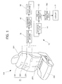
- a vehicle seat 10A includes a seat cushion 102 that is a region on which a seated person 80 shown in FIG. 5 and described later is seated, a seat back 104 that is a region rotatably attached to a back portion of the seat cushion 102 (hereinafter, a vehicle forward direction will be referred to as "front direction” and an opposite direction to the vehicle forward direction will be referred to as "back direction”) and that abuts on a backrest of the seated person 80, and a heartbeat measuring device 12 provided in the seat back 104 and including a sensor group 20 to be described later.
- the seat cushion 102 includes a urethane pad 102A, a urethane slab 102B adhesively bonded to an upper surface of the urethane pad 102A, and a skin 102C provided to further cover the urethane slab 102B. Furthermore, a ground electrode 20G, to be described later, is provided at a position facing the buttocks of the seated person 80 between the urethane pad 102A and the urethane slab 102B.
- the seat back 104 includes a urethane pad 104A, a urethane slab 104B adhesively bonded to an upper surface of the urethane pad 104A, and a skin 104C provided to further cover the urethane slab 104B.
- Sensors 20A to 20C, to be described later, are provided in the seat back 104 near on a surface of the seat back 104 (hereinafter, "front surface") facing the back of the seated person 80 between the urethane pad 104A and the urethane slab 104B.
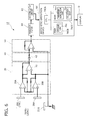
- the heartbeat measuring device 12 includes the sensor group 20 provided in the seat back 104, the ground electrode 20G, an instrumentation amplifier 30, a DC-component elimination circuit 40, an inverting amplifier 50, a bandpass filter 60, an A/D converter circuit 62, an arithmetic operation device 70C, and a display D.
- the sensor group 20 is an assembly constituted by the sensors 20A, 20B, and 20C each formed out of a conductive fabric tape, and is provided in the seat back 104 near the front surface of the seat back 104.
- each of the sensors 20A, 20B, and 20C functions to detect a body potential of the seated person 80 by being capacitively coupled to a body 800 of the seated person 80 via the skin 104C and clothes 802.
- a size of each of the sensors 20A, 20B, and 20C is 25 mm in height, 75 mm in width, and 1 mm in thickness.
- the sensors 20A, 20B, and 20C are arranged in the seat back 104 so that a longitudinal direction of the sensors 20A, 20B, and 20C is parallel to a width direction of the seat back 104. By so arranging, the seat back 104 can be downsized in a height direction.
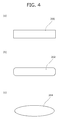
- a body-potential detection surface of each of the sensors 20A, 20B, and 20C has a shape having shorter and longer sides.
- the body-potential detection surface may be a rectangular detection surface 200 as shown in FIG. 4 (a) , a chamfered rectangular detection surface 202 as shown in FIG. 4 (b) or an elliptic detection surface 204 as shown in FIG. 4 (c) .
- the arrangement of the sensors 20A, 20B, and 20C in the seat back 104 in the height and width directions thereof will be described later in detail.
- the ground electrode 20G is formed out of a conductive fabric tape and provided in a region of the seat cushion 102 facing the buttocks of the seated person 80.
- the ground electrode 20G acquires a potential that serves as a reference potential used when offset signals contained in the signals from the sensors 20A, 20B, and 20C are eliminated.
- the ground electrode 20G is capacitively coupled to the body 800 of the seated person 80 via the skin 104C and the clothes 802.
- the ground electrode 20C is connected to plus-side input terminals of an operational amplifier 32 and the inverting amplifier 50 via a resistor using a ground electrode cable.
- the instrumentation amplifier 30 is constituted by operational amplifiers 30A, 30B, and 32.
- the operation amplifiers 30A and 30B amplify potential signals detected by the sensor group 20 and output the amplified potential signals to the operational amplifier 32.
- FIG. 6 particularly and only shows a circuit configuration including the sensors 20A and 20B. Other sensors shown later are the same circuit configuration, for example, the circuit configuration including the sensors 20A and 20B is a configuration in which the sensor 20B is replaced by the sensor 20C in FIG. 6 .
- the operational amplifier 32 is constituted by a differential amplifier and amplifies a difference signal between the potential signals output from the operational amplifiers 30A and 30B.
- the potential of the ground electrode 20G is applied to the plus-side input terminal of the operational amplifier 32.
- the ground electrode 20G is provided in the seat cushion 102 farther from the heart of the seated person 80 than the other sensors provided in the seat back 104, and capacitively coupled to the buttocks of the seated person 80.
- the ground electrode 20G therefore, can acquire the potential less influenced by electrocardiographic signals.
- a capacitor 42 acting as the DC-component elimination circuit 40 functions to eliminate low frequency components including a direct-current (DC) component and contained in the difference signal output from the operational amplifier 32, and provides AC coupling of an output terminal of the operation amplifier 32 to a minus-side input terminal of the inverting amplifier 50.
- DC direct-current
- the inverting amplifier 50 functions to invert the polarity of the potential difference signal from which the DC component is eliminated and to further amplify the resultant potential difference signal.
- the minus-side input terminal of the inverting amplifier 50 is connected to the capacitor 42 via a resistor, and the potential of the ground electrode 20G is applied to the plus-side input terminal of the inverting amplifier 50 as the reference potential.
- the bandpass filter 60 is provided to eliminate the low frequency components and high frequency components that are not regarded as frequencies of the electrocardiographic signals. By providing the bandpass filter 60, signals with frequencies relating to the electrocardiographic signals are input to the A/D converter circuit 62 in a restricted manner.
- the A/D converter circuit 62 converts an analog signal input from the inverting amplifier 50 via the bandpass filter 60 to a digital signal so as to use the digital signal as an input signal to the arithmetic operation device 70C.
- the arithmetic operation device 70C includes an arithmetic control CPU (Central Processing Unit) 70CA, a RAM (Random Access Memory) 70CB, and a ROM (Read Only Memory) 70CC. Furthermore, the signal input to the arithmetic operation device 70C is the potential difference signal that is the digital signal obtained by conversion in the A/D converter circuit 62, and a signal output from the arithmetic operation device 70C is an electric signal to be displayed on the display D.
- arithmetic control CPU Central Processing Unit
- RAM Random Access Memory
- ROM Read Only Memory
- the RAM 70CB temporarily stores therein parameters including signals under an arithmetic operation control and input/output signals.
- the RAM 70CB functions as a storage unit 700 that stores therein the digital-signal-converted potential difference signal and the other signals.
- the ROM 70CC stores therein programs executed by the CPU 70CA and predetermined parameters.
- a waveform generation unit 702 that generates voltage waveform data from the potential difference signal obtained from the sensor group 20 and a selection unit 704 that selects voltage waveform data having periodic amplitude corresponding to heart contraction are recorded in the ROM 70CC as the programs.
- the waveform generation unit 702 functions to generate voltage waveform data VAB and VAC with a vertical axis representing the potential difference signal and a horizontal axis representing time based on the potential difference signal between the potential signals output from the sensors 20A and 20B that is stored in the storage unit 700 and the potential difference signal between the potential signals output from the sensors 20A and 20C.
- the selection unit 704 functions to select the voltage waveform data corresponding to the heart contraction from between the voltage waveform data VAB and VAC, and to set the selected voltage waveform data as electrocardiographic waveform data VH. For example, a case is assumed where waveform data V1 shown in FIG. 7 (a) is generated as the voltage waveform data VAB, and where waveform data V2 shown in FIG. 7(b) or waveform data V3 shown in FIG. 7(c) is generated as the voltage waveform data VAC. In this case, the selection unit 704 selects the voltage waveform data V1 on which periodic R-waves clearly appear and that has high amplitude, that is, the voltage waveform data VAB.
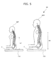
- an upper surface of the seat cushion 102 abutting on lower ends of the buttocks is defined as a cushion seat surface C in a state in which the seated person 80 (each of a female 80F and a male 80M) is seated on the seat cushion 102, and the cushion seat surface C is used as a reference for clearly expressing heights.
- FIG. 5 shows the female 80F as the seated person 80 having a small build and the male 80M as the seated person 80 having a large build, for the physically different seated people 80.
- the female 80F assumed as the seated person 80 having the small build is, for example, one of about 150-cm-tall Japanese female adults who are 5% of a total number accumulated from a shorter side.
- the male 80M assumed as the seated person 80 having the large build is, for example, one of about 190-cm-tall American male adults who are 95% of a total number accumulated from a shorter side.
- the heart of the female 80F is at a position of a height HF from the cushion seat surface C whereas the heart of the male 80M is at a position of a height HM from the cushion seat surface C.
- This height HF is about 370 mm for the female 80F who is about 150 cm tall whereas the height HM is about 550 mm for the male 80M who is about 190 cm tall.
- the following description will be given while using the female 80F as an expression replacing the seated person 80 having the small build and the male 80M as an expression replacing the seated person 80 having the large build.
- the arrangement of the sensors 20A, 20B, and 20C in the seat back 104 in the height and width directions thereof will be described.
- the sensor group 20 is arranged depending on the difference in the position of the heart due to the physical difference. Specifically, as shown in FIG. 3 , the sensor 20A placed in a lower portion among the three sensors is arranged so that a height 20HA of a center of the sensor 20A from the cushion seat surface C is smaller than the height HF of the heart of the female 80F. Moreover, the sensor 20A is provided offset rightward from a central axis by as much as a width 20WA while facing the front surface of the seat back 104. This width 20WA is arbitrarily set within a range from about 55 mm to about 75 mm.
- the sensor 20C placed in an upper portion among the three sensors is arranged so that a height 20HC of a center of the sensor 20C from the cushion seat surface C is larger than the height HM of the heart of the male 80M. Moreover, the sensor 20C is provided offset leftward from the central axis while facing the front surface of the seat back 104.
- the sensor 20B placed in an intermediate portion among the three sensors is arranged so that a height 20HB of a center of the sensor 20B from the cushion seat surface C is larger than the height HF of the heart of the female 80F.
- the sensor 20B is provided on the left and at the same position as the sensor 20C in the width direction while facing the front surface of the seat back 104. Note that the a length outward in a direction of a width between the sensors 20A and 20B, that is, a width of a zone 20AB is about 250 mm.
- the upper left sensor 20C and the lower right sensor 20A which face the front surface of the seat back 104, are arranged to obliquely hold the heart of the male 80M therebetween.
- An area defined as having the sensor 20A as a lower right corner and the sensor 20C as an upper left corner is assumed as a zone 20AC.
- This zone 20AC is the area that makes it possible to obtain a suited potential difference for detecting a potential of the heart of the male 80M. A heartbeat measuring method will be described later.
- the upper left sensor 20B and the lower right sensor 20A which face the front surface of the seat back 104, are arranged to obliquely hold the heart of the female 80F therebetween.
- An area defined as having the sensor 20A as a lower right corner and the sensor 20B as an upper left corner is assumed as a zone 20AB.
- This zone 20AB is the area that makes it possible to obtain a suited potential difference for detecting a potential of the heart of the female 80F.
- a vector of an electromotive force of the heart generated during expansion and contraction of the heart is generally in a direction from the right shoulder to the left leg if the seated person 80 is an ordinary person. This direction corresponds to a direction from upper left to lower right when facing the front surface of the seat back 104 in a state in which the seated person 80 is seated on the vehicle seat 10A. Therefore, the sensors 20A, 20B, and 20C are arranged so that a direction connecting the sensor 20A to the sensor 20B and that connecting the sensor 20A to the sensor 20C (indicated by two-dot chain lines in FIG. 3 ) are along the direction of the vector of the electromotive force of the heart. For this reason, a combination of the sensors 20A and 20B or that of the sensors 20A and 20C can be used to detect a large potential difference signal generated in response to the heart contraction (potential difference signal corresponding to the R-waves in an electrocardiogram).
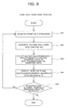
- a heartbeat measuring process performed by the heartbeat measuring device 12 configured as described above will be described with reference to FIG. 8 .
- the sensors 20A, 20B, and 20C detect the potential signals from the body 800 in response to start of a vehicle engine or to depression of a start switch.
- the potential signals detected by the sensors 20A and 20B and the sensor 20A and 20C are stored in the storage unit 700 of the arithmetic operation device 70C via the instrumentation amplifier 30, the DC-component elimination circuit 40, the inverting amplifier 50, the bandpass filter 60, and the A/D converter circuit 62 as the potential difference data. That is, the arithmetic operation device 70C acquires the potential difference data in the zones 20AB and 20AC (Step S01).
- the waveform generation unit 702 Based on the potential difference data acquired in the zones 20AB and 20AC, the waveform generation unit 702 generates the two voltage waveform data VAB and VAC with the respective axes representing the potential difference and the time (Step S02).
- the selection unit 704 selects the data synchronous with heartbeats and having the high amplitude of the R-waves from between the two voltage waveform data VAB and VAC, and sets the selected data as the electrocardiographic waveform data VH (Step S03).
- the arithmetic operation device 70C computes a peak interval at which a voltage (R-wave potential) exceeding a set threshold is detected by digitally filtering the electrocardiographic waveform data VH for emphasizing a waveform corresponding to QRS waves.
- the arithmetic operation device 70C sets an inverse of the peak interval as an instantaneous heart rate (heart rate per second) and further calculates the number of heartbeats detected per minute. That is, the arithmetic operation device 70C calculates the heart rate by arithmetic operation.
- the arithmetic operation device 70C transmits signals relating to the electrocardiographic waveform data VH and the heart rate to the display D so as to display the electrocardiographic waveform data VH and the heart rate on the display D (Step S04).
- the arithmetic operation device 70C determines whether an instruction to finish heartbeat measurement is received from a stop switch or the like (Step S05). If the arithmetic operation device 70C receives the instruction to finish the heartbeat measurement, the process ends. If the arithmetic operation device 70C does not receive the instruction to finish the heartbeat measurement, Steps S01 to S05 are repeated.
- the upper left sensor 20C and the lower right sensor 20A which face the front surface of the seat back 104, are arranged so as to obliquely hold the heart of the male 80M therebetween. Furthermore, the upper left sensor 20B and the lower right sensor 20A, which face to the front surface of the seat back 104, are arranged so as to obliquely hold the heart of the female 80F therebetween.
- the suited potential difference signal corresponding to the potential of the heart of the male 80M having the large build can be acquired.
- the suited potential difference signal corresponding to the potential of the heart of the female 80F having the small build can be acquired.
- the selection unit 704 of the arithmetic operation device 70C selects the voltage waveform data synchronous with the heartbeats and having the high amplitude from between the voltage waveform data VAB and VAC obtained in the zones 20AB and 20AC, and sets the selected voltage waveform data as the electrocardiographic waveform data VH. It is, therefore, possible to stably set the voltage waveform data containing the QRS waves as the electrocardiographic waveform data VH whoever is seated, the male 80M or the female 80F.
- a sensor group 21 according to a first modification will next be described.
- the same contents as those of the vehicle seat 10A according to the embodiment are not repeatedly described.
- the sensor group 21 according to the first modification is an assembly provided in the seat back 104 near the front surface of the seat back 104 and constituted by sensors 21A, 21B, and 21C arranged from below in order.
- the arrangement of the sensors 21A and 21C is identical to that of the sensors 20A and 20C according to the embodiment. It is assumed herein that an area defined as having the sensor 21A as a lower right corner and the sensor 21C as an upper left corner is a zone 21AC, and that an area defined as having the sensor 21A as a lower right corner and the sensor 21B as an upper left corner is a zone 21AB. Naturally, this zone 21AC is the area identical to the zone 20AC.
- the sensor group 21 according to the first modification differs from the sensor group 20 according to the embodiment as follows.
- a height 21HB of a center of the sensor 21B from the cushion seat surface C is larger than a height of a centerline CAC of the zone 21AC extending in a width direction of the zone 21AC.
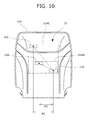
- a sensor group 22 according to a second modification is an assembly provided in the seat back 104 near the front surface of the seat back 104 and constituted by sensors 22A, 22B, and 22C arranged from below in order.
- the arrangement of the sensors 22A and 22C is identical to that of the sensors 20A and 20C according to the embodiment. It is assumed herein that an area defined as having the sensor 22A as a lower right corner and the sensor 22C as an upper left corner is a zone 22AC, and that an area defined as having the sensor 22A as a lower right corner and the sensor 22B as an upper left corner is a zone 22AB. Naturally, this zone 22AC is the area identical to the zone 20AC as well.
- the sensor group 22 according to the second modification is characterized in that a width W1 between centers of the sensors 22A and 22C is larger than a width W2 between centers of the sensors 22A and 22B.
- the male 80M and the female 80F differ in a contact height and a contact width with the seat back 104. That is, a detection range of the potential difference of the male 80M is preferably set wider than that of the female 80F so as to acquire a high potential difference in a contact range limited by the seated person 80 of each physical constitution.
- a configuration including the sensor group 22 according to the second modification it is possible to detect the potential difference suited for the female 80F in the zone 22AB and the potential difference suited for the male 80M in the zone 22AC.
- a sensor group 23 according to a third modification is an assembly provided in the seat back 104 near the front surface of the seat back 104 and constituted by four sensors 23A, 23B, 23C, and 23D arranged from below in order.
- the arrangement of the sensors 23A, 23B, and 23D is identical to that of the sensors 20A, 20B, and 20C according to the embodiment.
- heights 23HA, 23HB, and 23HD of the respective sensors 23A, 23B, and 23D in the seat back 104 from the cushion seat surface C are identical to the heights 20HA, 20HB, and 20HC of the respective sensors 20A, 20B, and 20C.
- the sensor 23C is provided to detect a potential signal containing QRS-waves of the male 80M. Owing to this, the sensor 23C is arranged above the sensor 23B and below the sensor 23D, and arranged vertically above the sensor 23A. The sensor 23C is arranged so that the heart of the male 80M is held obliquely between the sensors 23C and 23D.
- a zone 23AB is an area defined as having the sensor 23A as a lower right corner and the sensor 23B as an upper left corner.
- a zone 23AD is an area defined as having the sensor 23A as a lower right corner and the sensor 23D as an upper left corner.
- a zone 23CD is an area defined as having the sensor 23C as a lower right corner and the sensor 23D as an upper left corner.
- the zone 23AB is the area identical to the zone 20AB and the zone 23AD is the area identical to the zone 20AC.
- the zone 23AB is configured so that the sensor 20A is replaced by the sensor 23A and the sensor 20B is replaced by the sensor 23B.
- the zone 23AD is configured so that the sensor 20A is replaced by the sensor 23A and the sensor 20B is replaced by the sensor 23D.
- the zone 23CD is configured so that the sensor 20A is replaced by the sensor 23A and the sensor 20B is replaced by the sensor 23D.
- the two sensors 23A and 23C are combined with the sensor 23D each for detecting a potential difference.
- the sensor group 23 with such a configuration can detect a large potential difference if the seated person 80 is the male 80M having a vector of an electromotive force of the heart eccentric to a left axis.
- the sensor group 23 has more voltage waveform data to be selected by the selection unit 704 than the sensor group 21 by as much as the voltage waveform data detected by the combination of the sensors 23C and 23D.
- the heartbeat measuring device 12 can, therefore, obtain the electrocardiographic waveform data VH containing the QRS-waves more stably.
- a sensor group 24 according to a fourth modification is an assembly provided in the seat back 104 near the front surface of the seat back 104 and constituted by four sensors 24A, 24B, 24C, and 24D arranged from below in order. Note that heights of the sensors 24A, 24B, 24C, and 24D are identical to those of the sensors 23A, 23B, 23C, and 23D according to the third modification, respectively. The arrangement of the sensors 24C and 24D is identical to that of the sensors 23C and 23D according to the third modification. Similarly to the sensor 20A shown in FIG. 3 , the sensor 24A is provided at a position offset from the central axis of the seat back 104 by as much as the width 20WA.
- a width W3 between centers of the sensors 24A and 24D is smaller than a width W1 between centers of the sensors 24C and 24D.
- a width W4 between centers of the sensors 24A and 24B is smaller than the width W3.
- the sensor 24A is arranged closer to a center of the seat back 104 in the width direction than the sensor 24C, and the sensor 24B is arranged closer to the center of the seat back 104 in the width direction than the sensor 24D.
- a zone 24AB is an area defined as having the sensor 24A as a lower right corner and the sensor 24B as an upper left corner.
- a zone 24AD is an area defined as having the sensor 24A as a lower right corner and the sensor 24D as an upper left corner.
- a zone 24CD is an area defined as having the sensor 24C as a lower right corner and the sensor 24D as an upper left corner.
- the zone 24CD is the area identical to the zone 23CD.
- the sensor group 24 configured as described above can detect a large potential difference if the seated person 80 is the male 80M having the vector of the electromotive force of the heart eccentric to the left axis similarly to the sensor group 23 according to the third modification. Moreover, the sensor group 24 according to the fourth modification can detect a suited potential difference for the female 80F having a small body width in the zone 24AB, and detect a suited potential difference for the male 80M having a large body width in each of the zones 24AD and 24CD, thus providing sensor arrangements suited for physical constitutions.
- a sensor group 25 according to a fifth modification is an assembly provided in the seat back 104 near the front surface of the seat back 104 and constituted by four sensors 25A, 25B, 25C, and 25D arranged from below in order. Note that the arrangement of the sensors 25A and 25D is identical to that of the sensors 24A and 24D according to the fourth modification. Similarly to the sensor 20A shown in FIG. 3 , the sensors 25A and 25D are at positions of heights 25HA and 25HD from the cushion seat surface C to be offset from the central axis of the seat back 104 by as much as the width 20WA.
- the sensors 25B and 25C are arranged axisymmetric to the sensors 23B and 23C according to third modification about a centerline of the seat back 104 extending in the height direction.
- the sensor 25B is arranged in the seat back 104 so as to have a height 25HB identical to the height 23HB of the sensor 23B according to the third modification from the cushion seat surface C.
- the sensor 25C is arranged in the seat back 104 so as to have a height identical to the height 23HC of the sensor 23C according to the third modification from the cushion seat surface C. That is, the sensor 25C is arranged above the sensor 25B in the seat back 104.
- the sensor 25B is provided on a vertical line of the sensor 25A in the seat back 104
- the sensor 25C is provided on a vertical line of the sensor 25D.
- the sensor 25C is arranged in the seat back 104 so as to obliquely hold the heart of the female 80F and the heart of the seated person 80 of an intermediate build that is intermediate between those of the female 80F and the male 80M between the sensors 25C and 25A.
- the sensor 25B is arranged so as to obliquely hold the heart of the male 80M and the heart of the seated person 80 of the intermediate build between the sensors 25B and 25D.
- the sensors 25B and 25C are arranged so as to obliquely hold the heart of the seated person 80 of the intermediate build therebetween.
- an area defined as having the sensor 25A as a lower right corner and the sensor 25C as an upper left corner is a zone 25AC
- an area defined as having the sensor 25A as a lower right corner and the sensor 25D as an upper left corner is a zone 25AD
- an area defined as having the sensor 25B as a lower right corner and the sensor 25C as an upper left corner is a zone 25BC
- an area defined as having the sensor 25B as a lower right corner and the sensor 25D as an upper left corner is a zone 25BD.
- the zone 25AC is configured so that the sensor 20A is replaced by the sensor 25A and the sensor 20B is replaced by the sensor 25C.
- the zone 25AD is configured so that the sensor 20A is replaced by the sensor 25A and the sensor 20B is replaced by the sensor 25D.
- the zone 25BC is configured so that the sensor 20A is replaced by the sensor 25B and the sensor 20B is replaced by the sensor 25C.
- the zone 25BD is configured so that the sensor 20A is replaced by the sensor 25B and the sensor 20B is replaced by the sensor 25D.
- the two sensors 25A and 25B are combined with the sensor 25D each for detecting a potential difference. Furthermore, the two sensors 25A and 25B are combined with the sensor 25C each for detecting a potential difference.
- the sensor group 25 with such a configuration can detect a large potential difference if the seated person 80 is a person of the intermediate build.
- the sensor 25B is arranged at the lower right position relatively to the sensor 25C while facing the front surface of the seat back 104. That is, the sensors 25B and 25C are arranged in a direction along the vector of the electromotive force of the heart. A combination of the sensors 25B and 25C can, therefore, detect a high potential difference. Moreover, the sensor group 25 has more voltage waveform data to be selected by the selection unit 704 than the sensor group 23 by as much as the voltage waveform data detected by the combination of the sensors 25B and 25C. The heartbeat measuring device 12 can, therefore, obtain the electrocardiographic waveform data VH containing the QRS-waves more stably.
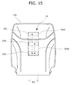
- a sensor group 26 according to a sixth modification is an assembly provided in the seat back 104 near the front surface of the seat back 104 and constituted by sensor units 26A, 26B, and 26C arranged in a line in a vertical direction from below in order.
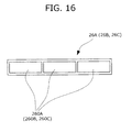
- the sensor units 26A, 26B, and 26C are constituted by three capacitively coupled sensors 260A, 260B, and 260C formed out of conductive fabric tapes, respectively, and arranged on a centerline extending vertically from the seat back 104.
- Heights of the sensor units 26A, 26B, and 26C in the seat back 104 from the cushion seat surface C are identical to the heights 20HA, 20HB, and 20HC of the sensors 20A, 20B, and 20C, respectively. That is, the sensor units 26A and 26B are provided so that the heart of the female 80F is located in a zone 26AB that is an area defined by positions of the sensor units 26A and 26B. Likewise, the sensor units 26A and 26C are provided so that the heart of the male 80M is located in a zone 26AC that is an area defined by positions of the sensor units 26A and 26C.
- the sensor group 26 is arranged so as to hold the heart of each of the male 80M and the female 80F between any one of the sensors 260B or 260C located at an upper left position and any one of the sensors 260A located at a lower right position while facing the front surface of the seat back 104.
- each sensor may be a sensor unit constituted by a plurality of sensors.
- each of the sensor units 26A, 26B, and 26C may be constituted by one sensor. Even with such a configuration, each of the sensor units 26A, 26B, and 26C can detect a large potential difference if the seated person has the vector of the electromotive force of the heart eccentric to the right axis.
- each of the sensor units 26A, 26B, and 26C preferably has a width W5 larger than the width of the sensor unit 20A since the zones 26AB and 26AC are limited in the width of the sensor.
- the number of sensors is three or four in the vehicle seat according to the embodiment and the modifications thereof, the number of sensors is not limited to this number but more plural sensors may be provided in light of the balance between the stability of the detection of the potential difference and manufacturing cost.
- the material may be a metal conductor having conduction, for example, conductive fiber and the like.
- this heartbeat measuring device includes the display for displaying electrocardiographic waveforms
- the device may also include a vibrating motor that is equipment for keeping the seated person awake, or an oscillator producing an alarm or a light-emitting unit emitting light as well as the display.
- the vehicle seat according to the embodiment is applicable for the purpose of monitoring a person who has heart disease.
- the display is preferably arranged at a position at which another passenger can monitor the operating state of the heart of the person with disease.
- the vehicle seat may be configured so that a seat (seats) other than the seat provided with the heartbeat measuring device includes (include) a vibrating motor that can vibrate the other seat (seats) to notify the other passenger (passengers) of the functional deterioration of the heart of the person having heart disease if the functional deterioration is detected.
- the seated person assumed to have the small build is the 150-cm-tall person and the seated person assumed to have the large build is the 190-cm-tall person by way of example
- the seated person of the small build and the seated person of the large build can be arbitrarily assumed.
- the seated people are set based on the physical constitution according to the assumption.
- the vehicle seat according to the present invention can easily detect electrocardiographic signals without need to directly attach a sensor to the body of the seated person since the vehicle seat includes the capacitively coupled sensors. It is also possible to measure heartbeats of the seated person other than the driver since no sensor is provided in the steering wheel.
- examples of the vehicle seat according to the present invention include not only seats of a motorbike and a motor scooter that are land-based vehicles but also those of a snowmobile and a personal watercraft, as well as vehicle seats of a straddle type vehicle such as a three-wheeled buggy or the like and a vehicle seat relating to a construction machine seat.
Landscapes
- Health & Medical Sciences (AREA)
- Life Sciences & Earth Sciences (AREA)
- Engineering & Computer Science (AREA)
- General Health & Medical Sciences (AREA)
- Heart & Thoracic Surgery (AREA)
- Biophysics (AREA)
- Animal Behavior & Ethology (AREA)
- Biomedical Technology (AREA)
- Veterinary Medicine (AREA)
- Medical Informatics (AREA)
- Molecular Biology (AREA)
- Surgery (AREA)
- Pathology (AREA)
- Physics & Mathematics (AREA)
- Public Health (AREA)
- Cardiology (AREA)
- Mechanical Engineering (AREA)
- Aviation & Aerospace Engineering (AREA)
- Transportation (AREA)
- Signal Processing (AREA)
- Physiology (AREA)
- Psychiatry (AREA)
- Developmental Disabilities (AREA)
- Child & Adolescent Psychology (AREA)
- Educational Technology (AREA)
- Hospice & Palliative Care (AREA)
- Psychology (AREA)
- Social Psychology (AREA)
- Computer Networks & Wireless Communication (AREA)
- Computer Vision & Pattern Recognition (AREA)
- Artificial Intelligence (AREA)
- Measurement And Recording Of Electrical Phenomena And Electrical Characteristics Of The Living Body (AREA)
- Seats For Vehicles (AREA)
- Measuring Pulse, Heart Rate, Blood Pressure Or Blood Flow (AREA)
Abstract
Description
- The present invention relates to a vehicle seat and relates to a vehicle seat having a function of measuring heartbeats.
- In recent years, there has been proposed a configuration for determining whether a driver has a health problem by detecting various parameters indicative of a driver's condition with views of preventing a serious accident that possibly occurs while the driver is driving a vehicle and so as to promptly notify the driver of the occurrence of the health problem.
- For example,
Patent Literature 1 discloses a measuring device including a plurality of surface electrodes arranged at respective positions on which the back, a region from the waist to the buttocks, and the femoral region of the driver abut. The measuring device suppresses signal noise by allowing one of the surface electrodes to acquire the potential of the neutral point of an amplifier, and determines abnormality by appropriately detecting heartbeat signals and respiration signals of the driver. - Patent Literature 2 discloses an electrocardiographic measuring device including two sensors arbitrarily arranged in a seat back and a ground electrode arranged in a seat cushion.
- Patent Literature 3 discloses a vehicle electrocardiographic measuring device including a sensor provided in a steering portion for detecting the body potential of a driver.
-
- Patent Document 1:
JP 2007-301175 A - Patent Document 2:
JP 2009-50679 A - Patent Document 3:
JP 2011-24902 A - Regions where a vehicle driver contacts a seat greatly differ between a case where the driver has a small build and a case where the driver has a large build. For example, in a case of the vehicle seat disclosed in
Patent Literature 1, irregularities occur in the signals obtained by the surface electrodes if drivers physically differ. - Furthermore, the electrocardiographic measuring device disclosed in Patent Literature 2 is intended to detect electrocardiographic signals using the two sensors provided in the seat back, and the sensors are not arranged depending on the physical difference. Owing to this, if the drivers physically differ, it is impossible to stably detect the electrocardiographic signals.
- Moreover, in a case of the electrocardiographic measuring device disclosed in Patent Literature 3, a seat provided with this device is limited to a driver' s seat provided with a steering wheel, and a measurement target person is limited to the driver who touches the steering wheel.
- The present invention has been made in view of these problems, and an object of the present invention is to make it possible to stably measure heartbeats even if seated people differ physically, and to measure even heartbeats of those other than a driver.
- The problem can be solved by a vehicle seat according to the present invention. The vehicle seat includes: a seat back on which a seated person leans; and a measuring device including a plurality of sensors that are capacitively coupled sensors acquiring body potentials of the seated person in a non-contact manner, and that are provided in the seat back; and an arithmetic operation device that computes electrical signals relating to the detected body potentials to obtain an electrocardiographic signal of the seated person, the measuring device measuring heartbeats of the seated person, wherein the sensors are provided to face the seated person in a range from a lower portion to an upper portion in the seat back, and include at least three sensors of a first sensor provided in the lower portion, a second sensor provided in an intermediate portion, and a third sensor provided in the upper portion, wherein the first sensor is arranged at a lower right position of a front surface of the seat back relatively to the second sensor and the third sensor when seen from a direction facing the front surface of the seat back, and the front surface is a surface of the seat back facing the seated person, wherein the second sensor is arranged above the first sensor and below the third sensor, wherein the first sensor and the third sensor are arranged so that a heart of the seated person is located in a first zone if the first zone is defined based on a position of the first sensor and a position of the third sensor and a second zone is defined based on the position of the first sensor and a position of the second sensor, and wherein the first sensor, the second sensor, and the third sensor transmit electrical signals at least relating to the body potentials detected in the first zone and the second zone to the arithmetic operation device.
- By doing so, even if seated people physically differ, it is possible to stably detect a large potential difference signal corresponding to the heart contraction of each seated person, and to measure the heartbeats of the seated person other than a driver by providing the sensors in seats other than a driver's seat. Furthermore, since the capacitively coupled sensors are provided in the seat back, the heartbeats can be measured without causing the seated person to feel inconvenience of attaching the sensor to the seated person.
- It is more preferable that the second sensor is provided at the position of a height larger than a height of a center of the first zone.
- By doing so, even if the seated person is a person of a small build having a small contact area, it is possible to provide a large difference signal between the detected body potentials.
- Moreover, it is preferable that a length in a direction of a width between the first sensor and the third sensor is larger than a length in a direction of a width between the first sensor and the second sensor.
- By so setting, it is possible to provide a large potential difference signal between the body potentials detected from the seated person of each physical constitution since the widths between the sensors are set depending on the body width of the seated person of the small build and that of the seated person of the large build.
- Furthermore, it is preferable that the plurality of sensors further include a fourth sensor above the first sensor and below the third sensor, and that the first sensor, the second sensor, the third sensor, and the fourth sensor transmit the body potentials detected in the first zone, the second zone, and a third zone to the arithmetic operation device for computing the body potentials to obtain the electrocardiographic signal of the seated person if the third zone is defined based on the position of the third sensor and a position of the fourth sensor.
- In this way, it is possible to stably obtain electrocardiographic signals by the arithmetic operation of the arithmetic operation device since the number of detected potential difference signals increases by increasing the number of sensors provided in the seat back.
- Moreover, it is preferable that each of the first sensor, the second sensor, and the third sensor includes a detection surface having shorter sides and longer sides, and is arranged so that a direction of the longer sides is along a width direction of the seat back.
- By doing so, the seat back can be downsized in the height direction.
- Furthermore, it is preferable that the measuring device measures the heartbeats by selecting data having periodic amplitude corresponding to a heart contraction from among data detected by the plurality of sensors defining the zones.
- By doing so, it is possible to stably measure the heartbeats based on the stable data corresponding to the heart contraction.
- According to the present invention, even if seated people physically differ, it is possible to stably detect a large potential difference signal corresponding to the heart contraction of each seated person, and to measure the heartbeats of even the seated person other than a driver. Furthermore, since the capacitively coupled sensors are provided in the seat back, the heartbeats can be measured without causing the seated person to feel inconvenience of attaching the sensor to the seated person.
- Furthermore, according to the present invention, even if the seated person is a person of a small build having a small contact area, it is possible to provide a large difference signal between the detected body potentials.
- Moreover, according to the present invention, it is possible to provide a large potential difference signal between the body potentials detected from the seated person of each physical constitution since the widths between the sensors are set depending on the body width of the seated person of the small build and that of the seated person of the large build.
- Furthermore, according to the present invention, it is possible to stably obtain electrocardiographic signals by the arithmetic operation of the arithmetic operation device since the number of detected potential difference signals increases by increasing the number of sensors provided in the seat back.
- Moreover, according to the present invention, the seat back can be downsized in the height direction.
- Furthermore, according to the present invention, it is possible to stably measure the heartbeats based on the stable data corresponding to the heart contraction.
-
- [
FIG. 1] FIG. 1 shows an overall configuration of a vehicle seat according to an embodiment. - [
FIG. 2] FIG. 2 is a cross-sectional view of a seat cushion and a seat back for showing arrangement positions of sensors. - [
FIG. 3] FIG. 3 is a front view of the seat back for showing the arrangement of the sensors. - [
FIG. 4] FIG. 4(a) shows a sensor having a rectangular detection surface,FIG. 4 (b) shows a sensor having a chamfered rectangular detection surface, andFIG. 4(c) shows a sensor having an elliptical detection surface. - [
FIG. 5] FIG. 5 shows a difference in heart height depending on a physical difference. - [
FIG. 6] FIG. 6 is a schematic diagram showing a circuit configuration and a configuration of an arithmetic operation device for detecting electrocardiographic signals. - [
FIG. 7] FIGS. 7(a) to 7(c) show examples of detected waveform data. - [
FIG. 8] FIG. 8 is a flowchart showing a flow of a heartbeat measuring process. - [
FIG. 9] FIG. 9 is a front view of a seatback for showing arrangement of sensors according to a first modification. - [
FIG. 10] FIG. 10 is a front view of a seatback for showing arrangement of sensors according to a second modification. - [
FIG. 11] FIG. 11 is a front view of a seatback for showing arrangement of sensors according to a third modification. - [
FIG. 12] FIGS. 12(a) to 12(c) show combinations of sensors for detecting a potential difference. - [
FIG. 13] FIG. 13 is a front view of a seatback for showing arrangement of sensors according to a fourth modification. - [
FIG. 14] FIG. 14 is a front view of a seatback for showing arrangement of sensors according to a fifth modification. - [
FIG. 15] FIG. 15 is a front view of a seatback for showing arrangement of sensors according to a sixth modification. - [
FIG. 16] FIG. 16 is a schematic diagram showing a configuration of the sensors according to the sixth modification. - An embodiment of a vehicle seat according to the present invention will be specifically described hereinafter with reference to the accompanying drawings.
- As shown in
FIG. 1 , avehicle seat 10A according to the embodiment includes aseat cushion 102 that is a region on which a seatedperson 80 shown inFIG. 5 and described later is seated, aseat back 104 that is a region rotatably attached to a back portion of the seat cushion 102 (hereinafter, a vehicle forward direction will be referred to as "front direction" and an opposite direction to the vehicle forward direction will be referred to as "back direction") and that abuts on a backrest of theseated person 80, and aheartbeat measuring device 12 provided in theseat back 104 and including asensor group 20 to be described later. - As shown in
FIG. 2 , theseat cushion 102 includes aurethane pad 102A, aurethane slab 102B adhesively bonded to an upper surface of theurethane pad 102A, and askin 102C provided to further cover theurethane slab 102B. Furthermore, aground electrode 20G, to be described later, is provided at a position facing the buttocks of theseated person 80 between theurethane pad 102A and theurethane slab 102B. - As shown in
FIG. 2 , theseat back 104 includes aurethane pad 104A, aurethane slab 104B adhesively bonded to an upper surface of theurethane pad 104A, and askin 104C provided to further cover theurethane slab 104B.Sensors 20A to 20C, to be described later, are provided in the seat back 104 near on a surface of the seat back 104 (hereinafter, "front surface") facing the back of the seatedperson 80 between theurethane pad 104A and theurethane slab 104B. - As shown in
FIG. 1 , theheartbeat measuring device 12 includes thesensor group 20 provided in the seat back 104, theground electrode 20G, aninstrumentation amplifier 30, a DC-component elimination circuit 40, an invertingamplifier 50, abandpass filter 60, an A/D converter circuit 62, anarithmetic operation device 70C, and a display D. - As shown in
FIG. 3 , thesensor group 20 is an assembly constituted by thesensors FIG. 2 , each of thesensors person 80 by being capacitively coupled to abody 800 of the seatedperson 80 via theskin 104C and clothes 802. A size of each of thesensors sensors sensors - It suffices that a body-potential detection surface of each of the
sensors rectangular detection surface 200 as shown inFIG. 4 (a) , a chamferedrectangular detection surface 202 as shown inFIG. 4 (b) or anelliptic detection surface 204 as shown inFIG. 4 (c) . The arrangement of thesensors - The
ground electrode 20G is formed out of a conductive fabric tape and provided in a region of theseat cushion 102 facing the buttocks of the seatedperson 80. Theground electrode 20G acquires a potential that serves as a reference potential used when offset signals contained in the signals from thesensors sensors ground electrode 20G is capacitively coupled to thebody 800 of the seatedperson 80 via theskin 104C and theclothes 802. Moreover, as shown inFIG. 6 , theground electrode 20C is connected to plus-side input terminals of anoperational amplifier 32 and the invertingamplifier 50 via a resistor using a ground electrode cable. - As shown in
FIG. 6 , theinstrumentation amplifier 30 is constituted byoperational amplifiers operation amplifiers sensor group 20 and output the amplified potential signals to theoperational amplifier 32.FIG. 6 particularly and only shows a circuit configuration including thesensors sensors sensor 20B is replaced by thesensor 20C inFIG. 6 . - The
operational amplifier 32 is constituted by a differential amplifier and amplifies a difference signal between the potential signals output from theoperational amplifiers - The potential of the
ground electrode 20G is applied to the plus-side input terminal of theoperational amplifier 32. As described above, theground electrode 20G is provided in theseat cushion 102 farther from the heart of the seatedperson 80 than the other sensors provided in the seat back 104, and capacitively coupled to the buttocks of the seatedperson 80. Theground electrode 20G, therefore, can acquire the potential less influenced by electrocardiographic signals. - A
capacitor 42 acting as the DC-component elimination circuit 40 functions to eliminate low frequency components including a direct-current (DC) component and contained in the difference signal output from theoperational amplifier 32, and provides AC coupling of an output terminal of theoperation amplifier 32 to a minus-side input terminal of the invertingamplifier 50. - The inverting
amplifier 50 functions to invert the polarity of the potential difference signal from which the DC component is eliminated and to further amplify the resultant potential difference signal. The minus-side input terminal of the invertingamplifier 50 is connected to thecapacitor 42 via a resistor, and the potential of theground electrode 20G is applied to the plus-side input terminal of the invertingamplifier 50 as the reference potential. - The
bandpass filter 60 is provided to eliminate the low frequency components and high frequency components that are not regarded as frequencies of the electrocardiographic signals. By providing thebandpass filter 60, signals with frequencies relating to the electrocardiographic signals are input to the A/D converter circuit 62 in a restricted manner. - The A/
D converter circuit 62 converts an analog signal input from the invertingamplifier 50 via thebandpass filter 60 to a digital signal so as to use the digital signal as an input signal to thearithmetic operation device 70C. - The
arithmetic operation device 70C includes an arithmetic control CPU (Central Processing Unit) 70CA, a RAM (Random Access Memory) 70CB, and a ROM (Read Only Memory) 70CC. Furthermore, the signal input to thearithmetic operation device 70C is the potential difference signal that is the digital signal obtained by conversion in the A/D converter circuit 62, and a signal output from thearithmetic operation device 70C is an electric signal to be displayed on the display D. - The RAM 70CB temporarily stores therein parameters including signals under an arithmetic operation control and input/output signals. The RAM 70CB functions as a
storage unit 700 that stores therein the digital-signal-converted potential difference signal and the other signals. - The ROM 70CC stores therein programs executed by the CPU 70CA and predetermined parameters. A
waveform generation unit 702 that generates voltage waveform data from the potential difference signal obtained from thesensor group 20 and aselection unit 704 that selects voltage waveform data having periodic amplitude corresponding to heart contraction are recorded in the ROM 70CC as the programs. - The
waveform generation unit 702 functions to generate voltage waveform data VAB and VAC with a vertical axis representing the potential difference signal and a horizontal axis representing time based on the potential difference signal between the potential signals output from thesensors storage unit 700 and the potential difference signal between the potential signals output from thesensors - The
selection unit 704 functions to select the voltage waveform data corresponding to the heart contraction from between the voltage waveform data VAB and VAC, and to set the selected voltage waveform data as electrocardiographic waveform data VH. For example, a case is assumed where waveform data V1 shown inFIG. 7 (a) is generated as the voltage waveform data VAB, and where waveform data V2 shown inFIG. 7(b) or waveform data V3 shown inFIG. 7(c) is generated as the voltage waveform data VAC. In this case, theselection unit 704 selects the voltage waveform data V1 on which periodic R-waves clearly appear and that has high amplitude, that is, the voltage waveform data VAB. - The arrangement of the
sensor group 20 for stably detecting body potentials irrespectively of a physical difference between theseated people 80 will be described. In the following description, an upper surface of theseat cushion 102 abutting on lower ends of the buttocks is defined as a cushion seat surface C in a state in which the seated person 80 (each of a female 80F and a male 80M) is seated on theseat cushion 102, and the cushion seat surface C is used as a reference for clearly expressing heights. - First, the seated
people 80 having a physical difference are defined as follows.FIG. 5 shows the female 80F as the seatedperson 80 having a small build and the male 80M as the seatedperson 80 having a large build, for the physically different seatedpeople 80. The female 80F assumed as the seatedperson 80 having the small build is, for example, one of about 150-cm-tall Japanese female adults who are 5% of a total number accumulated from a shorter side. Furthermore, the male 80M assumed as the seatedperson 80 having the large build is, for example, one of about 190-cm-tall American male adults who are 95% of a total number accumulated from a shorter side. - The heart of the female 80F is at a position of a height HF from the cushion seat surface C whereas the heart of the male 80M is at a position of a height HM from the cushion seat surface C. This height HF is about 370 mm for the female 80F who is about 150 cm tall whereas the height HM is about 550 mm for the male 80M who is about 190 cm tall. The following description will be given while using the female 80F as an expression replacing the seated
person 80 having the small build and the male 80M as an expression replacing the seatedperson 80 having the large build. - The arrangement of the
sensors sensor group 20 is arranged depending on the difference in the position of the heart due to the physical difference. Specifically, as shown inFIG. 3 , thesensor 20A placed in a lower portion among the three sensors is arranged so that a height 20HA of a center of thesensor 20A from the cushion seat surface C is smaller than the height HF of the heart of the female 80F. Moreover, thesensor 20A is provided offset rightward from a central axis by as much as a width 20WA while facing the front surface of the seat back 104. This width 20WA is arbitrarily set within a range from about 55 mm to about 75 mm. - Furthermore, the
sensor 20C placed in an upper portion among the three sensors is arranged so that a height 20HC of a center of thesensor 20C from the cushion seat surface C is larger than the height HM of the heart of the male 80M. Moreover, thesensor 20C is provided offset leftward from the central axis while facing the front surface of the seat back 104. - Furthermore, the
sensor 20B placed in an intermediate portion among the three sensors is arranged so that a height 20HB of a center of thesensor 20B from the cushion seat surface C is larger than the height HF of the heart of the female 80F. Moreover, thesensor 20B is provided on the left and at the same position as thesensor 20C in the width direction while facing the front surface of the seat back 104. Note that the a length outward in a direction of a width between thesensors - In the
sensor group 20 arranged as described above, the upperleft sensor 20C and the lowerright sensor 20A, which face the front surface of the seat back 104, are arranged to obliquely hold the heart of the male 80M therebetween. An area defined as having thesensor 20A as a lower right corner and thesensor 20C as an upper left corner is assumed as a zone 20AC. This zone 20AC is the area that makes it possible to obtain a suited potential difference for detecting a potential of the heart of the male 80M. A heartbeat measuring method will be described later. - Furthermore, the upper
left sensor 20B and the lowerright sensor 20A, which face the front surface of the seat back 104, are arranged to obliquely hold the heart of the female 80F therebetween. An area defined as having thesensor 20A as a lower right corner and thesensor 20B as an upper left corner is assumed as a zone 20AB. This zone 20AB is the area that makes it possible to obtain a suited potential difference for detecting a potential of the heart of the female 80F. - The reason for arranging the
sensors person 80 is an ordinary person. This direction corresponds to a direction from upper left to lower right when facing the front surface of the seat back 104 in a state in which the seatedperson 80 is seated on thevehicle seat 10A. Therefore, thesensors sensor 20A to thesensor 20B and that connecting thesensor 20A to thesensor 20C (indicated by two-dot chain lines inFIG. 3 ) are along the direction of the vector of the electromotive force of the heart. For this reason, a combination of thesensors sensors - A heartbeat measuring process performed by the
heartbeat measuring device 12 configured as described above will be described with reference toFIG. 8 . Thesensors body 800 in response to start of a vehicle engine or to depression of a start switch. - The potential signals detected by the
sensors sensor storage unit 700 of thearithmetic operation device 70C via theinstrumentation amplifier 30, the DC-component elimination circuit 40, the invertingamplifier 50, thebandpass filter 60, and the A/D converter circuit 62 as the potential difference data. That is, thearithmetic operation device 70C acquires the potential difference data in the zones 20AB and 20AC (Step S01). - Based on the potential difference data acquired in the zones 20AB and 20AC, the
waveform generation unit 702 generates the two voltage waveform data VAB and VAC with the respective axes representing the potential difference and the time (Step S02). - The
selection unit 704 selects the data synchronous with heartbeats and having the high amplitude of the R-waves from between the two voltage waveform data VAB and VAC, and sets the selected data as the electrocardiographic waveform data VH (Step S03). - The
arithmetic operation device 70C computes a peak interval at which a voltage (R-wave potential) exceeding a set threshold is detected by digitally filtering the electrocardiographic waveform data VH for emphasizing a waveform corresponding to QRS waves. Next, thearithmetic operation device 70C sets an inverse of the peak interval as an instantaneous heart rate (heart rate per second) and further calculates the number of heartbeats detected per minute. That is, thearithmetic operation device 70C calculates the heart rate by arithmetic operation. Next, thearithmetic operation device 70C transmits signals relating to the electrocardiographic waveform data VH and the heart rate to the display D so as to display the electrocardiographic waveform data VH and the heart rate on the display D (Step S04). - The
arithmetic operation device 70C determines whether an instruction to finish heartbeat measurement is received from a stop switch or the like (Step S05). If thearithmetic operation device 70C receives the instruction to finish the heartbeat measurement, the process ends. If thearithmetic operation device 70C does not receive the instruction to finish the heartbeat measurement, Steps S01 to S05 are repeated. - It is effective to set lower limit time that is inappropriate for an R-wave generation interval as an algorithm used for the arithmetic operation of the peak interval. Specifically, after detection of one R-wave, voltage signals detected at shorter intervals than this time are eliminated from a signal corresponding to a next R-wave. By doing so, it is possible to prevent the peak interval from being computed as a value that does not obviously correspond to a heart contraction cycle. Alternatively, if the peak interval exceeds an upper limit of a set range, for example, such a high voltage as to correspond to the voltage of the R-wave may be searched again at time near an intermediate point of the interval or the peak interval may be set as half of the time assuming that the R-wave is detected at the intermediate point. By doing so, even if the voltage corresponding to the R-wave cannot be temporarily detected due to, for example, a body motion or the like of the seated
person 80, it is possible to prevent the heart rate that is obviously erroneous from being output. - As described above, in the
vehicle seat 10A according to the embodiment, the upperleft sensor 20C and the lowerright sensor 20A, which face the front surface of the seat back 104, are arranged so as to obliquely hold the heart of the male 80M therebetween. Furthermore, the upperleft sensor 20B and the lowerright sensor 20A, which face to the front surface of the seat back 104, are arranged so as to obliquely hold the heart of the female 80F therebetween. In the zone 20AC defined by thesensors sensors - Moreover, the
selection unit 704 of thearithmetic operation device 70C selects the voltage waveform data synchronous with the heartbeats and having the high amplitude from between the voltage waveform data VAB and VAC obtained in the zones 20AB and 20AC, and sets the selected voltage waveform data as the electrocardiographic waveform data VH. It is, therefore, possible to stably set the voltage waveform data containing the QRS waves as the electrocardiographic waveform data VH whoever is seated, the male 80M or the female 80F. - A
sensor group 21 according to a first modification will next be described. In the following description, for making clearer the difference in features of the first modification from the embodiment, the same contents as those of thevehicle seat 10A according to the embodiment are not repeatedly described. - As shown in
FIG. 9 , thesensor group 21 according to the first modification is an assembly provided in the seat back 104 near the front surface of the seat back 104 and constituted bysensors sensors sensors sensor 21A as a lower right corner and thesensor 21C as an upper left corner is a zone 21AC, and that an area defined as having thesensor 21A as a lower right corner and thesensor 21B as an upper left corner is a zone 21AB. Naturally, this zone 21AC is the area identical to the zone 20AC. - The
sensor group 21 according to the first modification differs from thesensor group 20 according to the embodiment as follows. A height 21HB of a center of thesensor 21B from the cushion seat surface C is larger than a height of a centerline CAC of the zone 21AC extending in a width direction of the zone 21AC. By so arranging thesensor 21B and forming the zone 21AB wider than the zone 20AB, it is possible to detect a large potential difference from thesensors person 80 is the female 80F. - As shown in
FIG. 10 , asensor group 22 according to a second modification is an assembly provided in the seat back 104 near the front surface of the seat back 104 and constituted bysensors sensors sensors sensor 22A as a lower right corner and thesensor 22C as an upper left corner is a zone 22AC, and that an area defined as having thesensor 22A as a lower right corner and thesensor 22B as an upper left corner is a zone 22AB. Naturally, this zone 22AC is the area identical to the zone 20AC as well. - The
sensor group 22 according to the second modification is characterized in that a width W1 between centers of thesensors sensors - Because of the physical difference between the male 80M and the female 80F, the male 80M and the female 80F differ in a contact height and a contact width with the seat back 104. That is, a detection range of the potential difference of the male 80M is preferably set wider than that of the female 80F so as to acquire a high potential difference in a contact range limited by the seated
person 80 of each physical constitution. With a configuration including thesensor group 22 according to the second modification, it is possible to detect the potential difference suited for the female 80F in the zone 22AB and the potential difference suited for the male 80M in the zone 22AC. - As shown in
FIG. 11 , asensor group 23 according to a third modification is an assembly provided in the seat back 104 near the front surface of the seat back 104 and constituted by foursensors sensors sensors respective sensors respective sensors - The
sensor 23C is provided to detect a potential signal containing QRS-waves of the male 80M. Owing to this, thesensor 23C is arranged above thesensor 23B and below thesensor 23D, and arranged vertically above thesensor 23A. Thesensor 23C is arranged so that the heart of the male 80M is held obliquely between thesensors - As shown in
FIGS. 12 (a) to 12 (c) , a zone 23AB is an area defined as having thesensor 23A as a lower right corner and thesensor 23B as an upper left corner. A zone 23AD is an area defined as having thesensor 23A as a lower right corner and thesensor 23D as an upper left corner. A zone 23CD is an area defined as having thesensor 23C as a lower right corner and thesensor 23D as an upper left corner. The zone 23AB is the area identical to the zone 20AB and the zone 23AD is the area identical to the zone 20AC. - A circuit configuration relating to the
sensor group 23 constituted by the foursensors FIG. 6 . The zone 23AB is configured so that thesensor 20A is replaced by thesensor 23A and thesensor 20B is replaced by thesensor 23B. Likewise, the zone 23AD is configured so that thesensor 20A is replaced by thesensor 23A and thesensor 20B is replaced by thesensor 23D. Likewise, the zone 23CD is configured so that thesensor 20A is replaced by thesensor 23A and thesensor 20B is replaced by thesensor 23D. - In the
sensor group 23 configured as described above, the twosensors sensor 23D each for detecting a potential difference. Thesensor group 23 with such a configuration can detect a large potential difference if the seatedperson 80 is the male 80M having a vector of an electromotive force of the heart eccentric to a left axis. Thesensor group 23 has more voltage waveform data to be selected by theselection unit 704 than thesensor group 21 by as much as the voltage waveform data detected by the combination of thesensors heartbeat measuring device 12 can, therefore, obtain the electrocardiographic waveform data VH containing the QRS-waves more stably. - As shown in
FIG. 13 , asensor group 24 according to a fourth modification is an assembly provided in the seat back 104 near the front surface of the seat back 104 and constituted by foursensors sensors sensors sensors sensors sensor 20A shown inFIG. 3 , thesensor 24A is provided at a position offset from the central axis of the seat back 104 by as much as the width 20WA. - A width W3 between centers of the
sensors sensors sensors sensor 24A is arranged closer to a center of the seat back 104 in the width direction than thesensor 24C, and thesensor 24B is arranged closer to the center of the seat back 104 in the width direction than thesensor 24D. - Furthermore, a zone 24AB is an area defined as having the
sensor 24A as a lower right corner and thesensor 24B as an upper left corner. A zone 24AD is an area defined as having thesensor 24A as a lower right corner and thesensor 24D as an upper left corner. A zone 24CD is an area defined as having thesensor 24C as a lower right corner and thesensor 24D as an upper left corner. The zone 24CD is the area identical to the zone 23CD. - The
sensor group 24 configured as described above can detect a large potential difference if the seatedperson 80 is the male 80M having the vector of the electromotive force of the heart eccentric to the left axis similarly to thesensor group 23 according to the third modification. Moreover, thesensor group 24 according to the fourth modification can detect a suited potential difference for the female 80F having a small body width in the zone 24AB, and detect a suited potential difference for the male 80M having a large body width in each of the zones 24AD and 24CD, thus providing sensor arrangements suited for physical constitutions. - As shown in
FIG. 14 , asensor group 25 according to a fifth modification is an assembly provided in the seat back 104 near the front surface of the seat back 104 and constituted by foursensors sensors sensors sensor 20A shown inFIG. 3 , thesensors - The
sensors sensors - Specifically or in other words, the
sensor 25B is arranged in the seat back 104 so as to have a height 25HB identical to the height 23HB of thesensor 23B according to the third modification from the cushion seat surface C. Thesensor 25C is arranged in the seat back 104 so as to have a height identical to the height 23HC of thesensor 23C according to the third modification from the cushion seat surface C. That is, thesensor 25C is arranged above thesensor 25B in the seat back 104. Furthermore, thesensor 25B is provided on a vertical line of thesensor 25A in the seat back 104, and thesensor 25C is provided on a vertical line of thesensor 25D. - Moreover, the
sensor 25C is arranged in the seat back 104 so as to obliquely hold the heart of the female 80F and the heart of the seatedperson 80 of an intermediate build that is intermediate between those of the female 80F and the male 80M between thesensors sensor 25B is arranged so as to obliquely hold the heart of the male 80M and the heart of the seatedperson 80 of the intermediate build between thesensors sensors person 80 of the intermediate build therebetween. - It is assumed that an area defined as having the
sensor 25A as a lower right corner and thesensor 25C as an upper left corner is a zone 25AC, and that an area defined as having thesensor 25A as a lower right corner and thesensor 25D as an upper left corner is a zone 25AD. Furthermore, it is assumed that an area defined as having thesensor 25B as a lower right corner and thesensor 25C as an upper left corner is a zone 25BC, and that an area defined as having thesensor 25B as a lower right corner and thesensor 25D as an upper left corner is a zone 25BD. - A circuit configuration relating to the
sensor group 25 constituted by the foursensors FIG. 6 . The zone 25AC is configured so that thesensor 20A is replaced by thesensor 25A and thesensor 20B is replaced by thesensor 25C. Likewise, the zone 25AD is configured so that thesensor 20A is replaced by thesensor 25A and thesensor 20B is replaced by thesensor 25D. Likewise, the zone 25BC is configured so that thesensor 20A is replaced by thesensor 25B and thesensor 20B is replaced by thesensor 25C. Likewise, the zone 25BD is configured so that thesensor 20A is replaced by thesensor 25B and thesensor 20B is replaced by thesensor 25D. - In the
sensor group 25 configured as described above, the twosensors sensor 25D each for detecting a potential difference. Furthermore, the twosensors sensor 25C each for detecting a potential difference. Thesensor group 25 with such a configuration can detect a large potential difference if the seatedperson 80 is a person of the intermediate build. - The
sensor 25B is arranged at the lower right position relatively to thesensor 25C while facing the front surface of the seat back 104. That is, thesensors sensors sensor group 25 has more voltage waveform data to be selected by theselection unit 704 than thesensor group 23 by as much as the voltage waveform data detected by the combination of thesensors heartbeat measuring device 12 can, therefore, obtain the electrocardiographic waveform data VH containing the QRS-waves more stably. - As shown in
FIG. 15 , asensor group 26 according to a sixth modification is an assembly provided in the seat back 104 near the front surface of the seat back 104 and constituted bysensor units - As shown in
FIG. 16 , thesensor units sensors - Heights of the
sensor units sensors sensor units sensor units sensor units sensor units - That is, the
sensor group 26 is arranged so as to hold the heart of each of the male 80M and the female 80F between any one of thesensors sensors 260A located at a lower right position while facing the front surface of the seat back 104. - Even with such a configuration, it is possible to stably detect the potential of the heart irrespectively of the physical constitution by selecting the data on which the QRS-waves appear most clearly from among the voltage waveform data acquired by combinations of the
sensors - Moreover, with such a configuration, even if the body of the seated
person 80 is offset to one side in the width direction of the seat by a centrifugal force generated when the vehicle driven by the seatedperson 80 makes a turn, the contact of the seatedperson 80 with thesensor group 26 is easily maintained and thesensor group 26 can stably acquire the potential difference. - The sensors provided in the
vehicle seat 10A according to the embodiment and the sensors according to the modifications other than the embodiment may be configured similarly to thesensor units - Furthermore, each of the
sensor units sensor units sensor units sensor unit 20A since the zones 26AB and 26AC are limited in the width of the sensor. - While the present invention has been described specifically based on the embodiment and the modifications thereof, the present invention is not limited to the embodiment and the modifications. Various changes such as a combination of the respective features and the like can be made of the invention within the scope of the spirit of the invention.
- For example, while the number of sensors is three or four in the vehicle seat according to the embodiment and the modifications thereof, the number of sensors is not limited to this number but more plural sensors may be provided in light of the balance between the stability of the detection of the potential difference and manufacturing cost.
- While it has been described that the sensors constituting the sensor groups and the ground electrodes are each formed out of the conductive fabric tape, the material may be a metal conductor having conduction, for example, conductive fiber and the like.
- While it has been described that this heartbeat measuring device includes the display for displaying electrocardiographic waveforms, the device may also include a vibrating motor that is equipment for keeping the seated person awake, or an oscillator producing an alarm or a light-emitting unit emitting light as well as the display.
- Moreover, the vehicle seat according to the embodiment is applicable for the purpose of monitoring a person who has heart disease. In this case, the display is preferably arranged at a position at which another passenger can monitor the operating state of the heart of the person with disease. Alternatively, the vehicle seat may be configured so that a seat (seats) other than the seat provided with the heartbeat measuring device includes (include) a vibrating motor that can vibrate the other seat (seats) to notify the other passenger (passengers) of the functional deterioration of the heart of the person having heart disease if the functional deterioration is detected.
- While it has been described above that the seated person assumed to have the small build is the 150-cm-tall person and the seated person assumed to have the large build is the 190-cm-tall person by way of example, the seated person of the small build and the seated person of the large build can be arbitrarily assumed. For example, in a case where only American adults are assumed to be seated or only children are assumed to be seated, the seated people are set based on the physical constitution according to the assumption. By determining the positions of the upper left and lower right sensors, which face the front surface of the seat back, so as to hold the heart of the person set as a basis therebetween and determining the position of another sensor therebetween in a state in which the person of the physical constitution as the basis is seated, similar effects can be attained.
- Moreover, the vehicle seat according to the present invention can easily detect electrocardiographic signals without need to directly attach a sensor to the body of the seated person since the vehicle seat includes the capacitively coupled sensors. It is also possible to measure heartbeats of the seated person other than the driver since no sensor is provided in the steering wheel.
- It is assumed that examples of the vehicle seat according to the present invention include not only seats of a motorbike and a motor scooter that are land-based vehicles but also those of a snowmobile and a personal watercraft, as well as vehicle seats of a straddle type vehicle such as a three-wheeled buggy or the like and a vehicle seat relating to a construction machine seat.
-
- 10A
- Vehicle seat
- 102
- Seat cushion
- 104
- Seat back
- 12
- Heartbeat measuring device
- 20, 21, 22, 23, 24, 25, 26
- Sensor group
- 20A, 21A, 22A, 23A, 24A, 25A, 260A
- Sensor (first sensor)
- 20B, 21B, 22B, 23C, 24C, 25C, 260B
- Sensor (second sensor)
- 20C, 21C, 22C, 23D, 24D, 25D, 260C
- Sensor (third sensor)
- 23B, 24B, 25B
- (Fourth sensor)
- 26A, 26B, 26C
- Sensor unit
- 20AC, 21AC, 22AC, 23AD, 24AD, 25AD, 26AC
- Zone (first zone)
- 20AB, 21AB, 22AB, 23AB, 24AB, 25AC, 26AB
- Zone (second zone)
- 23CD, 24CD, 25BD
- Zone (third zone)
- 25BC
- Zone (fourth zone)
- 70C
- Arithmetic operation device
- 700
- Storage unit
- 702
- Waveform generation unit
- 704
- Selection unit
- 80
- Seated person
- 80M
- Male
- 80F
- Female
- C
- Cushion seat surface
- D
- Display
Claims (6)
- A vehicle seat comprising:a seat back on which a seated person leans; anda measuring device comprising a plurality of sensors that are capacitively coupled sensors acquiring body potentials of the seated person in a non-contact manner, and that are provided in the seat back, and an arithmetic operation device that computes electrical signals relating to the detected body potentials to obtain an electrocardiographic signal of the seated person, the measuring device measuring heartbeats of the seated person,wherein the sensors are provided to face the seated person in a range from a lower portion to an upper portion in the seat back, and comprise at least three sensors of a first sensor provided in the lower portion, a second sensor provided in an intermediate portion, and a third sensor provided in the upper portion,wherein the first sensor is arranged at a lower right position of a front surface of the seat back relatively to the second sensor and the third sensor when seen from a direction facing the front surface of the seat back, the front surface being a surface of the seat back facing the seated person,wherein the second sensor is arranged above the first sensor and below the third sensor,wherein the first sensor and the third sensor are arranged so that a heart of the seated person is located in a first zone if the first zone is defined based on a position of the first sensor and a position of the third sensor and a second zone is defined based on the position of the first sensor and a position of the second sensor, andwherein the first sensor, the second sensor, and the third sensor transmit electrical signals at least relating to the body potentials detected in the first zone and the second zone to the arithmetic operation device.
- The vehicle seat according to claim 1, wherein the second sensor is provided at the position of a height larger than a height of a center of the first zone.
- The vehicle seat according to claim 1 or 2, wherein a length in a direction of a width between the first sensor and the third sensor is larger than a length in a direction of a width between the first sensor and the second sensor.
- The vehicle seat according to any one of claims 1 to 3, wherein
the plurality of sensors further comprise a fourth sensor above the first sensor and below the third sensor, and
the first sensor, the second sensor, the third sensor, and the fourth sensor transmit the body potentials detected in the first zone, the second zone, and a third zone to the arithmetic operation device for computing the body potentials to obtain the electrocardiographic signal of the seated person if the third zone is defined based on the position of the third sensor and a position of the fourth sensor. - The vehicle seat according to any one of claims 1 to 4, wherein each of the first sensor, the second sensor, and the third sensor comprises a detection surface having shorter sides and longer sides, and is arranged so that a direction of the longer sides is along a width direction of the seat back.
- The vehicle seat according to any one of claims 1 to 5, wherein the measuring device measures the heartbeats by selecting data having periodic amplitude corresponding to a heart contraction from among data detected by the plurality of sensors defining the zones.
Applications Claiming Priority (2)
| Application Number | Priority Date | Filing Date | Title |
|---|---|---|---|
| JP2012095788A JP6068820B2 (en) | 2012-04-19 | 2012-04-19 | Vehicle seat |
| PCT/JP2013/061520 WO2013157608A1 (en) | 2012-04-19 | 2013-04-18 | Vehicle-use seat |
Publications (2)
| Publication Number | Publication Date |
|---|---|
| EP2839779A1 true EP2839779A1 (en) | 2015-02-25 |
| EP2839779A4 EP2839779A4 (en) | 2015-04-15 |
Family
ID=49383560
Family Applications (1)
| Application Number | Title | Priority Date | Filing Date |
|---|---|---|---|
| EP13778140.7A Withdrawn EP2839779A4 (en) | 2012-04-19 | 2013-04-18 | SEAT FOR USE IN A VEHICLE |
Country Status (4)
| Country | Link |
|---|---|
| US (1) | US20150133804A1 (en) |
| EP (1) | EP2839779A4 (en) |
| JP (1) | JP6068820B2 (en) |
| WO (1) | WO2013157608A1 (en) |
Cited By (3)
| Publication number | Priority date | Publication date | Assignee | Title |
|---|---|---|---|---|
| EP2997891A4 (en) * | 2013-05-17 | 2016-05-04 | Ts Tech Co Ltd | VITAL INFORMATION MEASURING DEVICE AND VEHICLE SEAT |
| ES2585211A1 (en) * | 2016-03-31 | 2016-10-04 | Centro Tecnológico Del Mueble Y La Madera De La Región De Murcia | Back-up device for measuring electrocardiogram and / or respiratory rate |
| CN107788968A (en) * | 2017-03-07 | 2018-03-13 | 中南大学 | A kind of contactless multi-lead electrocardiogram monitor system based on array type capacity electrode |
Families Citing this family (18)
| Publication number | Priority date | Publication date | Assignee | Title |
|---|---|---|---|---|
| US9468388B2 (en) * | 2013-04-25 | 2016-10-18 | Denso Corporation | Electrocardiographic waveform measuring apparatus |
| JP5776723B2 (en) * | 2013-04-25 | 2015-09-09 | 株式会社デンソー | ECG waveform measuring device |
| BR112016030185A2 (en) | 2014-09-23 | 2021-09-08 | Rr Sequences Inc | Digital processing module (dpm), system and method for providing electrocardiogram (ecg) signals to a human body |
| JP6905198B2 (en) * | 2015-03-27 | 2021-07-21 | テイ・エス テック株式会社 | Seat |
| WO2016158759A1 (en) | 2015-03-27 | 2016-10-06 | テイ・エス テック株式会社 | Chair |
| US10160544B2 (en) * | 2015-09-09 | 2018-12-25 | Airbus Group India Private Limited | Aircraft occupant health, safety, and comfort management |
| US10176694B2 (en) * | 2015-09-09 | 2019-01-08 | Airbus Group India Private Limited | Aircraft occupant seat for aircraft occupant health, safety, and comfort management |
| JP6475680B2 (en) | 2016-02-05 | 2019-02-27 | テイ・エス テック株式会社 | Biological information measuring device |
| WO2017135263A1 (en) * | 2016-02-05 | 2017-08-10 | テイ・エス テック株式会社 | Bioinformation measurement device |
| JP6803679B2 (en) * | 2016-04-14 | 2020-12-23 | Joyson Safety Systems Japan株式会社 | Buckle and in-vehicle system |
| US11517240B2 (en) * | 2016-04-29 | 2022-12-06 | Freer Logic, Inc. | Non-contact body and head based monitoring of brain electrical activity |
| JP2018102710A (en) * | 2016-12-27 | 2018-07-05 | 株式会社豊田中央研究所 | Electrocardiographic measurement apparatus, method, and program |
| DE202017105144U1 (en) | 2017-08-28 | 2017-09-05 | Faurecia Autositze Gmbh | Vehicle seat system |
| JP7191576B2 (en) * | 2018-07-31 | 2022-12-19 | ヌヴォトンテクノロジージャパン株式会社 | BIOLOGICAL SIGNAL MEASURING DEVICE AND CONTROL METHOD |
| JP7239850B2 (en) * | 2019-07-03 | 2023-03-15 | テイ・エス テック株式会社 | sheet |
| WO2022072656A1 (en) * | 2020-09-30 | 2022-04-07 | Joyson Safety Systems Acquisition Llc | Force sensing seat belt sensor assembly |
| WO2023032120A1 (en) * | 2021-09-02 | 2023-03-09 | 日本電信電話株式会社 | Heartbeat detection method and heartbeat detection device |
| JP7643281B2 (en) | 2021-09-29 | 2025-03-11 | トヨタ紡織株式会社 | Seat |
Family Cites Families (12)
| Publication number | Priority date | Publication date | Assignee | Title |
|---|---|---|---|---|
| US6509747B2 (en) * | 2000-03-21 | 2003-01-21 | Honda Giken Kogyo Kabushiki Kaisha | Apparatus for detecting seated condition |
| JP2007195690A (en) * | 2006-01-25 | 2007-08-09 | Matsushita Electric Works Ltd | Portable electrocardiograph |
| JP2007301175A (en) * | 2006-05-11 | 2007-11-22 | Goto Ikueikai | Bioelectric signal collection device |
| JP5057070B2 (en) * | 2007-07-31 | 2012-10-24 | 株式会社エクォス・リサーチ | ECG sensor |
| CN101896120B (en) * | 2007-12-12 | 2012-10-10 | 皇家飞利浦电子股份有限公司 | Sleep position detection |
| JP4962735B2 (en) * | 2008-01-25 | 2012-06-27 | 株式会社エクォス・リサーチ | Biological information acquisition device |
| JP4993123B2 (en) * | 2008-01-25 | 2012-08-08 | 株式会社エクォス・リサーチ | Biological information acquisition device |
| JP2011024902A (en) | 2009-07-28 | 2011-02-10 | Toyota Motor Corp | Electrocardiographic device for vehicle |
| JP5196191B2 (en) * | 2009-08-04 | 2013-05-15 | 株式会社デンソー | Biological sensing device for vehicles |
| JP2011156215A (en) * | 2010-02-02 | 2011-08-18 | Denso Corp | Electrode for biological signal and biological information measuring system |
| JP5573282B2 (en) * | 2010-03-26 | 2014-08-20 | アイシン精機株式会社 | Biological information detection device |
| WO2012038867A1 (en) * | 2010-09-22 | 2012-03-29 | Koninklijke Philips Electronics N.V. | Method and device for identifying a subject in a sensor based monitoring system |
-
2012
- 2012-04-19 JP JP2012095788A patent/JP6068820B2/en active Active
-
2013
- 2013-04-18 US US14/395,375 patent/US20150133804A1/en not_active Abandoned
- 2013-04-18 EP EP13778140.7A patent/EP2839779A4/en not_active Withdrawn
- 2013-04-18 WO PCT/JP2013/061520 patent/WO2013157608A1/en not_active Ceased
Cited By (5)
| Publication number | Priority date | Publication date | Assignee | Title |
|---|---|---|---|---|
| EP2997891A4 (en) * | 2013-05-17 | 2016-05-04 | Ts Tech Co Ltd | VITAL INFORMATION MEASURING DEVICE AND VEHICLE SEAT |
| US10244959B2 (en) | 2013-05-17 | 2019-04-02 | Ts Tech Co., Ltd. | Vital information measurement device and vehicle seat |
| US10765334B2 (en) | 2013-05-17 | 2020-09-08 | Ts Tech Co., Ltd. | Vital information measurement device and vehicle seat |
| ES2585211A1 (en) * | 2016-03-31 | 2016-10-04 | Centro Tecnológico Del Mueble Y La Madera De La Región De Murcia | Back-up device for measuring electrocardiogram and / or respiratory rate |
| CN107788968A (en) * | 2017-03-07 | 2018-03-13 | 中南大学 | A kind of contactless multi-lead electrocardiogram monitor system based on array type capacity electrode |
Also Published As
| Publication number | Publication date |
|---|---|
| US20150133804A1 (en) | 2015-05-14 |
| WO2013157608A1 (en) | 2013-10-24 |
| JP6068820B2 (en) | 2017-01-25 |
| EP2839779A4 (en) | 2015-04-15 |
| JP2013220322A (en) | 2013-10-28 |
Similar Documents
| Publication | Publication Date | Title |
|---|---|---|
| US20150133804A1 (en) | Vehicle seat | |
| US10117589B2 (en) | Vehicle seat | |
| US10765334B2 (en) | Vital information measurement device and vehicle seat | |
| JP4962735B2 (en) | Biological information acquisition device | |
| US20080071177A1 (en) | Bioinformation Sensor | |
| JP2011024902A (en) | Electrocardiographic device for vehicle | |
| JP6411264B2 (en) | Sheet | |
| Matsuda et al. | ECG monitoring of a car driver using capacitively-coupled electrodes | |
| WO2016158758A1 (en) | Seat with detector | |
| EP2839985A1 (en) | Vehicle seat | |
| JP6550844B2 (en) | Sheet | |
| Yang et al. | Vehicle driver's ECG and sitting posture monitoring system | |
| JP6800564B2 (en) | Vehicle seat | |
| US12569180B2 (en) | Electrocardiographic signal measurement device and electrocardiographic signal measurement system technical field | |
| US20160183834A1 (en) | Semi-contact-type ecg measurement system and measurement method thereof | |
| JP6731785B2 (en) | Reliability determination device and reliability determination method | |
| US20250366756A1 (en) | Electrocardiogram data detection device | |
| Son et al. | Lumbar cushion based real-time ECG sensing system for monitoring driver's state | |
| JP2019195651A (en) | Sheet | |
| JP2016185778A (en) | Vehicle seat | |
| JP7239850B2 (en) | sheet | |
| TW201739421A (en) | Biological information acquisition device characterized by being capable of precisely acquiring human biological information |
Legal Events
| Date | Code | Title | Description |
|---|---|---|---|
| PUAI | Public reference made under article 153(3) epc to a published international application that has entered the european phase |
Free format text: ORIGINAL CODE: 0009012 |
|
| 17P | Request for examination filed |
Effective date: 20141118 |
|
| AK | Designated contracting states |
Kind code of ref document: A1 Designated state(s): AL AT BE BG CH CY CZ DE DK EE ES FI FR GB GR HR HU IE IS IT LI LT LU LV MC MK MT NL NO PL PT RO RS SE SI SK SM TR |
|
| AX | Request for extension of the european patent |
Extension state: BA ME |
|
| RA4 | Supplementary search report drawn up and despatched (corrected) |
Effective date: 20150316 |
|
| RIC1 | Information provided on ipc code assigned before grant |
Ipc: A61B 5/0428 20060101ALI20150310BHEP Ipc: A61B 5/0408 20060101AFI20150310BHEP Ipc: B60R 21/015 20060101ALI20150310BHEP Ipc: A61B 5/0452 20060101ALI20150310BHEP Ipc: B60N 2/44 20060101ALI20150310BHEP Ipc: A61B 5/0478 20060101ALI20150310BHEP |
|
| DAX | Request for extension of the european patent (deleted) | ||
| TPAC | Observations filed by third parties |
Free format text: ORIGINAL CODE: EPIDOSNTIPA |
|
| 17Q | First examination report despatched |
Effective date: 20160329 |
|
| STAA | Information on the status of an ep patent application or granted ep patent |
Free format text: STATUS: THE APPLICATION IS DEEMED TO BE WITHDRAWN |
|
| 18D | Application deemed to be withdrawn |
Effective date: 20170627 |