EP2839560B1 - Motorkreiselpumpe mit anschlusskasten - Google Patents
Motorkreiselpumpe mit anschlusskasten Download PDFInfo
- Publication number
- EP2839560B1 EP2839560B1 EP13708688.0A EP13708688A EP2839560B1 EP 2839560 B1 EP2839560 B1 EP 2839560B1 EP 13708688 A EP13708688 A EP 13708688A EP 2839560 B1 EP2839560 B1 EP 2839560B1
- Authority
- EP
- European Patent Office
- Prior art keywords
- plug
- rotary pump
- pump according
- terminal box
- motorized rotary
- Prior art date
- Legal status (The legal status is an assumption and is not a legal conclusion. Google has not performed a legal analysis and makes no representation as to the accuracy of the status listed.)
- Active
Links
Images

Classifications
-
- H—ELECTRICITY
- H02—GENERATION; CONVERSION OR DISTRIBUTION OF ELECTRIC POWER
- H02G—INSTALLATION OF ELECTRIC CABLES OR LINES, OR OF COMBINED OPTICAL AND ELECTRIC CABLES OR LINES
- H02G3/00—Installations of electric cables or lines or protective tubing therefor in or on buildings, equivalent structures or vehicles
- H02G3/02—Details
- H02G3/08—Distribution boxes; Connection or junction boxes
- H02G3/081—Bases, casings or covers
- H02G3/083—Inlets
-
- F—MECHANICAL ENGINEERING; LIGHTING; HEATING; WEAPONS; BLASTING
- F04—POSITIVE - DISPLACEMENT MACHINES FOR LIQUIDS; PUMPS FOR LIQUIDS OR ELASTIC FLUIDS
- F04D—NON-POSITIVE-DISPLACEMENT PUMPS
- F04D13/00—Pumping installations or systems
- F04D13/02—Units comprising pumps and their driving means
- F04D13/06—Units comprising pumps and their driving means the pump being electrically driven
- F04D13/0693—Details or arrangements of the wiring
-
- H—ELECTRICITY
- H02—GENERATION; CONVERSION OR DISTRIBUTION OF ELECTRIC POWER
- H02G—INSTALLATION OF ELECTRIC CABLES OR LINES, OR OF COMBINED OPTICAL AND ELECTRIC CABLES OR LINES
- H02G3/00—Installations of electric cables or lines or protective tubing therefor in or on buildings, equivalent structures or vehicles
- H02G3/02—Details
- H02G3/08—Distribution boxes; Connection or junction boxes
- H02G3/086—Assembled boxes
Definitions
- the invention relates to a motor centrifugal pump having an electronic components having, attached to the motor terminal box, lead to the electrical cable.
- From the EP 0 447 869 A1 is an electrical connection between two wires by means of insulation displacement technology in a housing known, wherein the connection is effected in that two halves of the housing are pressed into one another.
- a plug does not disclose this font.
- the object of the invention is to facilitate in a pump of the type mentioned the connection work and thus attaching and contacting the cable and to provide secure connections, especially in a hard to reach pump.
- On the terminal box therefore, a box-shaped plug is detachably plugged which forms an inner terminal space in which the electrical cables are inserted and connected. This will allow the installer to fix the leads in the plug away from the assembled pump and then the pre-assembled one Connect the plug to the pump box with the electronics, without having to make individual conductor contacts. This results in a simple construction to a lesser and easier work and a secure contact.
- a protected and secure position of the plug is given when the plug within the terminal box partially or completely rests.
- the plug can be partially or completely enclosed by the terminal box.
- a power supply cable and a signal transmitting signal cable is connected to the plug as a control line and used in the interior of the plug at least one separate contact block, are fixed to the conductor of the cable contacting.
- the contact block has a protruding, in particular molded, connector strip which, when the plug is plugged in, contacts mating contacts of the electronic circuit board of the connection box with its contacts contacted.
- the connector strip at the bottom of the connector before, in case of the terminal box fixed connector in the junction box penetrate.
- the contact block is inserted in the direction parallel to the axis of the motor in the plug.
- the plug is inserted in the direction of axis-parallel direction to the motor axis in the terminal box. It is advantageous if the plug rests positively in the terminal box. In this case, the plug can engage with at least 50 percent of its volume within the junction box in particular form-fitting manner.
- a particularly secure contact of the plug in the terminal box is achieved when the plug is inserted against the pressure of a spring element in the terminal box to the contact position and held in the contact position by a holding element.
- the retaining element may be a screw and / or a releasable locking element. A contact is thus only given when the screw is tightened.
- an additionally integrated spring system can push the plug against the contacting direction.
- the interior of the plug is closed by a cover through which the connector holding the connector box extending screw. It is also proposed for this purpose that the cables are each held by a clamping device tensile strength on the plug.
- the cables are securely held on the plug when the cable ends with their cable sheath in each case in a hollow connector formed on the plug eino, with a union nut over the connecting piece, which exerts a clamping force on the outside of the cable sheath. It is advantageous if on the cable sheath a coaxial clamping ring is located, the clamping cam, clamping fingers or clamping claws and is moved by the union nut against a pin located in the inner cone to press the clamping cam, clamping fingers or clamping claws against the cable sheath.
- the assembly is further facilitated if the plug is divided along a dividing plane in an upper and a lower region in particular two halves, the lower portion of the junction box is divided in particular with two halves, the lower portion of the junction box in particular with his / her Control block / contact blocks contacted.
- the parting line can run centrally through the connecting pieces such that the nozzle axes lie in the parting plane. It is also advantageous if the upper half of the plug is hinged to the lower half, wherein the hinge point is located on the side facing away from the connecting piece of the plug.
- a particularly secure contact is given when the two connector halves penetrating screw down beyond the bottom of the lower already protrudes and penetrates into a threaded bore of the terminal box, wherein screwed in the threaded bore state, the contacts of the plug and / or the contact block / contact blocks Contact with the mating contacts of the terminal box.
- FIG. 1 To FIG. 1 is on the front, the pump housing facing away from the end face of a pump motor, a terminal box (terminal box) 1 made of plastic attached in particular welded, that the bottom 2 of the junction box 1 on the engine front side of the electric motor, not shown (in particular a centrifugal motor pump) is applied.
- a terminal box terminal box 1 made of plastic attached in particular welded
- the bottom 2 of the junction box 1 on the engine front side of the electric motor not shown (in particular a centrifugal motor pump) is applied.
- the electrical connections of the electronic and electrical components of the junction box 1 with the electric motor in the drawing are not shown.
- a box-shaped plug with terminal space (terminal chamber, terminal box, terminal box) made of plastic positively inserted axially parallel to the motor axis, protrude to the two parallel arranged connecting piece 5 outside of the front, one of which the power supply cable 6 and the other the connected to the terminal box electronics signal cable 7 receives.
- the plug 4 is at least 50 percent of its volume within the junction box 1 in particular a form-fitting.
- the conductive strands of both cables 6, 7 are electrically connected to the contact block 8.
- the plug 4 is held in the inserted state by a screw 11 which extends through an upper cover 10 and the plug 4 and extends beyond the underside of the plug 4, hineinzuich with its lower end in a threaded bore of the junction box 1 and held by a locking ring to be. By tightening the screw 11 ensures that a contact is made in the terminal box 1.
- the plug 4 overcomes when pressed into the interior 3 of the junction box 1, a compression spring, which is stretched by the impressions.
- the plug 4 is in this case held in the in-state by a retaining means against the spring pressure, which is a screw or a releasable locking element. If the holding means is released, the spring pushes the plug 4 out of the connection box 1.
- connection box 1 After insertion of the plug 4, the interior 3 of the connection box 1 is closed by a cover 10, which is held by a screw 11 on the plug 4 or the terminal box 1.
- each cable end of the cable 6, 7 is guided by a clamping ring 12 for strain relief, which is pressure-loaded via a seal 13 and a union nut 14, which is screwed onto the free end of the connecting piece 5.
- the clamping ring has clamping cams, clamping fingers or clamping claws and is moved by the union nut against a located in the connection piece 5 inner cone to press the clamping cam, clamping fingers or clamping claws against the cable sheath.
- these clamping parts are integrated in the lower and upper regions 4a, 4b, which will be described below.
- the plug 4 is divided into an upper 4a and lower region 4b (or upper connector part 4a, lower connector part 4b), wherein the parting plane extends substantially horizontally and centrally through the connecting pieces 5.
- the lid 10 is unnecessary and the upper portion 4a is fixed to the lower portion 4b by at least one screw.
- the two areas or parts 4a, 4b are hinged to each other, wherein the hinge point is located on the back of the plug 4.
Landscapes
- Engineering & Computer Science (AREA)
- Architecture (AREA)
- Civil Engineering (AREA)
- Structural Engineering (AREA)
- Mechanical Engineering (AREA)
- General Engineering & Computer Science (AREA)
- Motor Or Generator Frames (AREA)
- Structures Of Non-Positive Displacement Pumps (AREA)
Description
- Die Erfindung betrifft eine Motorkreiselpumpe mit einem elektronische Bauteile aufweisenden, am Motor befestigten Anschlusskasten, zu dem elektrische Kabel führen.
- Es ist bekannt, an dem Elektronikgehäuse (Klemmenkasten) einer Motorkreiselpumpe den Stecker eines Stromversorgungskabels zu befestigen. Soll die Elektronik zusätzlich mit einem Signalkabel verbunden werden, so muss eine Kontaktierung des Signalkabels zudem vorgenommen werden. Das Befestigen und Konstruieren der Kabel an der Pumpe bedeutet für den Monteur nicht unerhebliche Arbeiten, die bei einer schwer zugänglichen Pumpe nicht leicht durchführbar sind. Aus der
EP 1 452 739 ist es an sich bekannt, an dem Klemmenkasten einer Pumpe einen Stecker anzustecken, um eine Anschlussleitung zu befestigen. Der Stecker bildet aber keinen inneren Klemmraum, um dort zwei oder mehr Kabel anzuschließen , sondern ist lediglich für eine einzige elektrische Anschlussleitung vorgesehen. Aus derEP 0 447 869 A1 ist eine elektrische Verbindung zwischen zwei Adern mittels Schneid-Klemmtechnik in einem Gehäuse bekannt, wobei die Verbindung dadurch erfolgt, dass zwei Hälften des Gehäuses ineinander gedrückt werden. Einen Stecker offenbart diese Schrift nicht. Aufgabe der Erfindung ist es, bei einer Pumpe der eingangs genannten Art die Anschlussarbeiten und damit das Befestigen und Kontaktieren der Kabel zu erleichtern und sichere Verbindungen zu schaffen, insbesondere bei einer schwer zugänglichen Pumpe. Am Anschlusskasten ist daher ein kastenförmiger Stecker lösbar angesteckt der einen inneren Klemmraum bildet, in dem die elektrischen Kabel hineingeführt und angeschlossen sind. Hierdurch wird es dem Monteur ermöglicht, in Entfernung von der montierten Pumpe die Leitungen im Stecker zu befestigen und danach den vormontierten Stecker am die Elektronik aufweisenden Pumpenanschlusskasten anzustecken, ohne dann noch einzelne Leiterkontaktierungen vornehmen zu müssen. Dies führt bei einfacher Konstruktion zu einer geringeren und leichteren Arbeit und einer sicheren Kontaktierung. - Eine geschützte und sichere Lage des Steckers ist dann gegeben, wenn der Stecker innerhalb des Anschlusskastens teilweise oder vollständig einliegt. Hierbei kann der Stecker vom Anschlusskasten teilweise oder vollständig umschlossen sein. Erfindungsgemäß ist am Stecker ein Stromversorgungskabel und ein Signale übertragendes Signalkabel als Steuerleitung angeschlossen und im Innenraum des Steckers mindestens ein separater Kontaktblock eingesetzt, an dem Leiter der Kabel kontaktierend befestigt sind.
- Der Stecker hat damit mehrere Funktionen:
- Aufnahme der insbesondere zwei Anschlusskabel
- Zugentlastung der Kabel
- Trennung von Netz- und Signalleitungen
- Kontaktierung der Netz- und Signalleitungen
- direkte Kontaktierung auf der Elektronikplatine durch integrierten Kontaktblock im Stecker.
- Besonders vorteilhaft ist hierbei, wenn der Kontaktblock eine vorstehende insbesondere angeformte Steckleiste aufweist, die bei eingestecktem Stecker mit seinen Kontakten Gegenkontakte der Elektronikplatine des Anschlusskastens kontaktiert. Hierzu steht die Steckleiste an der Unterseite des Steckers vor, um bei am Anschlusskasten befestigtem Stecker in den Anschlusskasten einzudringen. Vorzugsweise ist der Kontaktblock in achsparalleler Richtung zur Motorenachse in dem Stecker eingesteckt.
- Auch wird vorgeschlagen, dass der Stecker in achsparalleler Richtung zur Motorenachse in den Anschlusskasten eingesteckt ist. Von Vorteil ist, wenn der Stecker formschlüssig im Anschlusskasten einliegt. Dabei kann der Stecker mit mindestens 50 Prozent seines Volumens innerhalb des Anschlusskastens insbesondere formschlüssig einliegen.
- Eine besonders sichere Kontaktierung des Steckers im Anschlusskasten wird erreicht, wenn der Stecker gegen den Druck eines Federelementes in den Anschlusskasten bis zur Kontaktstellung eingeschoben und in der Kontaktstellung durch ein Halteelement gehalten ist. Hierbei kann das Halteelement eine Schraube und/oder ein lösbares Rastelement sein. Eine Kontaktierung ist somit nur gegeben, wenn die Schraube angezogen ist. Hierbei kann ein zusätzlich integriertes Federsystem den Stecker gegen die Kontaktierungsrichtung drücken.
- Zur Absicherung wird vorgeschlagen, dass der Innenraum des Steckers von einem Deckel verschlossen ist, durch den die den Anschlussstecker am Anschlusskasten haltende Schraube verläuft. Auch wird hierzu vorgeschlagen, dass die Kabel am Stecker jeweils durch eine Klemmeinrichtung zugfest gehalten sind.
- Die Kabel sind am Stecker sicher gehalten, wenn die Kabelenden mit ihrem Kabelmantel jeweils in einem am Stecker angeformten hohlen Anschlussstutzen einliegen, wobei über dem Anschlussstutzen eine Überwurfmutter liegt, die außen auf dem Kabelmantel eine Klemmkraft ausübt. Dabei ist von Vorteil, wenn auf dem Kabelmantel ein koaxialer Klemmring liegt, der Klemmnocken, Klemmfinger oder Klemmkrallen aufweist und durch die Überwurfmutter gegen einen im Anschlussstutzen befindlichen Innenkonus bewegt wird, um die Klemmnocken, Klemmfinger oder Klemmkrallen gegen den Kabelmantel zu drücken.
- Die Montage wird noch dadurch erleichtert, wenn der Stecker entlang einer Trennebene in einen oberen und einen unteren Bereich insbesondere zwei Hälften geteilt ist, wobei der untere Bereich den Anschlusskasten insbesondere mit zwei Hälften geteilt ist, wobei der untere Bereich den Anschlusskasten insbesondere mit seinem/seinen Kontrollblock/Kontaktblöcken kontaktiert. Hierbei kann die Trennebene mittig durch die Anschlussstutzen derart verlaufen, dass die Stutzenachsen in der Trennebene liegen. Ferner ist von Vorteil, wenn die obere Hälfte des Steckers an der unteren Hälfte angelenkt ist, wobei die Gelenkstelle auf der dem Anschlußstutzen abgewandten Seite des Steckers liegt.
- Eine besonders sichere Kontaktierung ist gegeben wenn, die die beiden Steckerhälften durchdringende Schraube nach unten über die Unterseite des unteren Bereits hinaussteht und in eine Gewindebohrung des Anschlusskastens eindringt, wobei im in der Gewindebohrung eingeschraubtem Zustand die Kontakte des Steckers und/oder des Kontaktblockes/der Kontaktblöcke mit den Gegenkontakten des Anschlusskastens kontaktieren.
- Zwei Ausführungsbeispiele der Erfindung sind in den Zeichnungen dargestellt und werden im Folgenden näher beschrieben. Es zeigen
- Figur 1
- ein erstes Ausführungsbeispiel von Anschlusskasten und Stecker im auseinander genommenen Zustand,
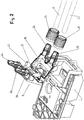
- Figur 2
- ein zweites Ausführungsbeispiel.
- Nach
Figur 1 ist auf der vorderen, dem Pumpengehäuse abgewandten Stirnseite eines Pumpenmotors ein Anschlusskasten (Klemmenkasten) 1 aus Kunststoff derart befestigt insbesondere angeschweißt, dass die Unterseite 2 des Anschlusskastens 1 an der Motorenstirnseite des nicht dargestellten Elektromotors (insbesondere einer Kreiselmotorpumpe) anliegt. Hierbei sind die elektrischen Verbindungen der elektronischen und elektrischen Bauteile des Anschlusskastens 1 mit dem Elektromotor in der Zeichnung nicht dargestellt. - Im Innenraum 3 des Anschlusskastens 1 ist ein kastenförmiger Stecker mit Klemmraum (Klemmkammer, Klemmbox, Klemmkasten) aus Kunststoff formschlüssig achsparallel zur Motorenachse eingesteckt, an dem zwei zueinander parallel angeordnete Anschlussstutzen 5 außen an der Vorderseite vorstehen, von denen einer das Stromversorgungskabel 6 und der andere das mit der Anschlusskastenelektronik verbundene Signalkabel 7 aufnimmt. Der Stecker 4 liegt mit mindestens 50 Prozent seines Volumens innerhalb des Anschlusskastens 1 insbesondere formschlüssig ein.
- Im Stecker 4 ist achsparallel zur Motorenachse mindestens ein Kontaktblock 8 insbesondere aus Kunststoff eingesteckt, an dem auf der dem Motor zugewandten Seite eine angeformte Steckleiste 9 vorsteht, die durch eine Öffnung im Boden des Steckers 4 hindurchragt und in den Innenraum 3 des Anschlusskastens 1 so weit hineinragt, dass die Steckleiste mit ihren Kontakten die Gegenkontakte der Elektronikplatine des Anschlusskastens 1 kontaktiert. Hierbei sind die leitenden Litzen beider Kabel 6, 7 am Kontaktblock 8 elektrisch angeschlossen.
- Der Stecker 4 ist im eingestecktem Zustand durch eine Schraube 11 gehalten, die durch einen oberen Deckel 10 und den Stecker 4 verläuft und über die Unterseite des Steckers 4 hinausragt, um mit ihrem unteren Ende in eine Gewindebohrung des Anschlusskastens 1 hineinzureichen und durch einen Sicherungsring gehalten zu sein. Durch ein Anziehen der Schraube 11 wird sichergestellt, dass eine Kontaktierung im Anschlusskasten 1 erfolgt.
- In einer Ausführung überwindet der Stecker 4 bei seinem Eindrücken in den Innenraum 3 des Anschlusskastens 1 eine Druckfeder, die durch das Eindrücken gespannt wird. Der Stecker 4 wird hierbei im einliegenden Zustand durch ein Haltemittel gegen den Federdruck festgehalten, das eine Schraube oder ein lösbares Rastelement ist. Wird das Haltemittel gelöst, so drückt die Feder den Stecker 4 aus dem Anschlusskasten 1 heraus.
- Nach dem Einstecken des Steckers 4 wird der Innenraum 3 des Anschlusskastens 1 durch einen Deckel 10 verschlossen, der durch eine Schraube 11 am Stecker 4 oder am Anschlusskasten 1 gehalten ist.
- In den Anschlussstutzen 5 ist jedes Kabelende der Kabel 6, 7 durch einen Klemmring 12 zur Zugentlastung geführt, der über eine Dichtung 13 und eine Überwurfmutter 14 druckbelastet ist, die auf das freie Ende des Anschlussstutzens 5 aufgeschraubt ist. Der Klemmring weist Klemmnocken, Klemmfinger oder Klemmkrallen auf und wird durch die Überwurfmutter gegen einen im Anschlussstutzen 5 befindlichen Innenkonus bewegt, um die Klemmnocken, Klemmfinger oder Klemmkrallen gegen den Kabelmantel zu drücken. Alternativ sind diese Klemmteile in dem unteren und oberen Bereich 4a, 4b integriert, die im Folgenden beschrieben werden.
- In einer weiteren Ausführung ist der Stecker 4 in einen oberen 4a und unteren Bereich 4b (bzw. Steckeroberteil 4a, Steckerunterteil 4b) geteilt, wobei die Trennebene im Wesentlichen waagerecht und mittig durch die Anschlussstutzen 5 verläuft. Damit erübrigt sich der Deckel 10 und der obere Bereich 4a ist am unteren Bereich 4b durch mindestens eine Schraube befestigt. Hierbei sind die beiden Bereiche bzw. Teile 4a, 4b aneinander angelenkt, wobei die Gelenkstelle auf der Rückseite des Steckers 4 liegt.
Claims (19)
- Motorkreiselpumpe mit einem elektronische Bauteile aufweisenden, am Motor befestigten Anschlusskasten (1), zu dem elektrische Kabel (6,7) führen, wobei am Anschlusskasten (11) ein kastenförmiger Stecker (4) lösbar angesteckt ist, der einen inneren Klemmraum bildet, in dem die elektrischen Kabel (6) hineingeführt und angeschiossen sind und am Stecker (4) ein Stromversorgungskabel (6) und ein Signale übertragendes Signalkabel (7) als Steuerleitung angeschlossen sind, dadurch gekennzeichnet dass im Klemmraum des Steckers (4) mindestens ein separater Kontaktblock (8) eingesetzt ist, an dem Leiter der Stromversorgungskabel (6) und der Signalkabel (7) kontaktierend befestigt sind.
- Motorkreiselpumpe nach Anspruch 1, dadurch gekennzeichnet, dass der Stecker (4) innerhalb des Anschlusskastens (1) teilweise oder vollständig einliegt.
- Motorkreiselpumpe nach Anspruch 2, dadurch gekennzeichnet, dass der Stecker (4) vom Anschlusskasten (1) teilweise oder vollständig umschlossen ist.
- Motorkreiselpumpe nach einem der vorherigen Ansprüche, dadurch gekennzeichnet, dass der Kontaktblock (8) eine vorstehende insbesondere angeformte Steckleiste (9) aufweist, die bei angestecktem Stecker (4) mit seinen Kontakten Gegenkontakte der Elektronikplatine des Anschlusskastens (1) kontaktiert.
- Motorkreiselpumpe nach Anspruch 4, dadurch gekennzeichnet, dass die Steckleiste an der Unterseite des Steckers (4) vorsteht, um bei am Anschlusskasten (1) befestigten Stecker in den Anschlusskasten einzudringen.
- Motorkreiselpumpe nach einem der vorherigen Ansprüche, dadurch gekennzeichnet, dass der Kontaktblock (8) in achsparalleler Richtung zur Motorenachse in dem Stecker (4) eingesteckt ist.
- Motorkreiselpumpe nach einem der vorherigen Ansprüche, dadurch gekennzeichnet, dass der Stecker (4) in achsparalleler Richtung zur Motorenachse in dem Anschlusskasten (1) eingesteckt ist.
- Motorkreiselpumpe nach einem der vorherigen Ansprüche, dadurch gekennzeichnet, dass der Stecker (4) formschlüssig im Anschlusskasten (1) einliegt.
- Motorkreiselpumpe nach einem der vorherigen Ansprüche, dadurch gekennzeichnet, dass der Stecker (4) mit mindestens 50 Prozent seines Volumens innerhalb des Anschlusskastens (1) insbesondere formschlüssig einliegt.
- Motorkreiselpumpe nach einem der vorherigen Ansprüche, dadurch gekennzeichnet, dass der Stecker (4) gegen den Druck eines Federelementes in den Anschlusskasten (1) bis zur Kontaktstellung eingeschoben und in der Kontaktstellung durch ein Halteelement (11) gehalten ist.
- Motorkreiselpumpe nach Anspruch 10, dadurch gekennzeichnet, dass das Halteelement eine Schraube (11) oder ein lösbares Rastelement ist.
- Motorkreiselpumpe nach einem der vorherigen Ansprüche, dadurch gekennzeichnet, dass der Innenraum des Steckers (4) von einem Deckel (10) verschlossen ist, durch den die den Stecker am Anschlusskasten (1) haltende Schraube verläuft.
- Motorkreiselpumpe nach einem der vorherigen Ansprüche, dadurch gekennzeichnet, dass die Kabel am Stecker (4) jeweils durch eine Klemmeinrichtung zugfest gehalten sind.
- Motorkreiselpumpe nach einem der vorherigen Ansprüche, dadurch gekennzeichnet, dass die Kabelenden mit ihrem Kabelmantel jeweils in einem am Stecker (4) angeformten hohlen Anschlussstutzen (5) einliegen, wobei über dem Anschlussstutzen eine Überwurfmutter (14) liegt, die außen auf den Kabelmantel eine Klemmkraft ausübt.
- Motorkreiselpumpe nach Anspruch 14, dadurch gekennzeichnet, dass auf dem Kabelmantel ein koaxialer Klemmring (12) liegt, der Klemmnocken, Klemmfinger oder Klemmkrallen aufweist und durch die Überwurfmutter gegen einen im Anschlussstutzen (5) befindlichen Innenkonus bewegt wird, um die Klemmnocken, Klemmfinger oder Klemmkrallen gegen den Kabelmantel zu drücken.
- Motorkreiselpumpe nach einem der vorherigen Ansprüche, dadurch gekennzeichnet, dass der Stecker (4) entlang einer Trennebene in einen oberen und einen unteren Bereich (4a, 4b) insbesondere zwei Hälften geteilt ist, wobei der untere Bereich (4b) den Anschlusskasten (1) insbesondere mit seinem/seinen Kontaktblock/Kontaktblöcken (8) kontaktiert.
- Motorkreiselpumpe nach Anspruch 16, dadurch gekennzeichnet, dass die Trennebene mittig durch die Anschlussstutzen (5) derart verläuft, dass die Stutzenachsen in der Trennebene liegen.
- Motorkreiselpumpe nach Anspruch 16 oder 17, dadurch gekennzeichnet, dass die obere Hälfte (4a) des Steckers (4) an der unteren Hälfte (4b) angelenkt ist, wobei die Gelenkstelle auf der dem Anschlußstutzen (5) abgewandten Seite des Steckers liegt.
- Motorkreiselpumpe nach einem der vorherigen Ansprüche, dadurch gekennzeichnet, dass die die beiden Steckerhälften (4a, 4b) durchdringende Schraube (11) nach unten über die Unterseite des unteren Bereits (4b) hinaussteht und in eine Gewindebohrung des Anschlusskastens (1) eindringt, wobei im in der Gewindebohrung eingeschraubtem Zustand die Kontakte des Steckers (4) und/oder des Kontaktblockes/der Kontaktblöcke (8) mit den Gegenkontakten des Anschlusskastens (1) kontaktieren.
Applications Claiming Priority (2)
| Application Number | Priority Date | Filing Date | Title |
|---|---|---|---|
| DE102012007962A DE102012007962A1 (de) | 2012-04-20 | 2012-04-20 | Motorkreiselpumpe mit Anschlusskasten |
| PCT/EP2013/000644 WO2013156099A2 (de) | 2012-04-20 | 2013-03-06 | Motorkreiselpumpe mit anschlusskasten |
Publications (2)
| Publication Number | Publication Date |
|---|---|
| EP2839560A2 EP2839560A2 (de) | 2015-02-25 |
| EP2839560B1 true EP2839560B1 (de) | 2017-08-30 |
Family
ID=47845910
Family Applications (1)
| Application Number | Title | Priority Date | Filing Date |
|---|---|---|---|
| EP13708688.0A Active EP2839560B1 (de) | 2012-04-20 | 2013-03-06 | Motorkreiselpumpe mit anschlusskasten |
Country Status (4)
| Country | Link |
|---|---|
| EP (1) | EP2839560B1 (de) |
| CN (1) | CN104350654B (de) |
| DE (1) | DE102012007962A1 (de) |
| WO (1) | WO2013156099A2 (de) |
Families Citing this family (3)
| Publication number | Priority date | Publication date | Assignee | Title |
|---|---|---|---|---|
| DE102015004470A1 (de) * | 2015-04-04 | 2016-10-06 | AMK Arnold Müller GmbH & Co. KG | Anschlussverfahren zur kostengünstigen Steuerung eines Elektronikmotors |
| DE102020210229B4 (de) | 2020-08-12 | 2022-03-10 | Festo Se & Co. Kg | Prozesstechnik-Gerät, Ventilanordnung und Verfahren |
| DE102021118376A1 (de) | 2021-07-15 | 2023-01-19 | KSB SE & Co. KGaA | Kabelabdeckung mit Kabelführung |
Citations (1)
| Publication number | Priority date | Publication date | Assignee | Title |
|---|---|---|---|---|
| EP0447869A1 (de) * | 1990-03-19 | 1991-09-25 | Walter Rose GmbH & Co. KG | Klemmverbinder für Kabel |
Family Cites Families (16)
| Publication number | Priority date | Publication date | Assignee | Title |
|---|---|---|---|---|
| US4451750A (en) * | 1981-02-03 | 1984-05-29 | Elektro-Mechanik Gmbh | Protective arrangement for a plug-connected electric motor sealed against pressure, vapors and radiation |
| US4880391A (en) * | 1988-06-30 | 1989-11-14 | General Electric Company | Apparatus for connecting multiple windings |
| DE8814031U1 (de) * | 1988-11-09 | 1990-03-22 | Grote & Hartmann Gmbh & Co Kg, 5600 Wuppertal | Zentraler Stromverteiler, insbesondere für Kraftfahrzeuge |
| DE4040610C1 (de) * | 1990-12-19 | 1992-06-17 | Volkswagen Ag, 3180 Wolfsburg, De | |
| EP0551195A1 (de) * | 1992-01-07 | 1993-07-14 | Bml Enterprises Ltd. | Elektromotor mit Schalter |
| DE19511170A1 (de) * | 1995-03-28 | 1996-10-02 | Wilo Gmbh | Doppelpumpe mit übergeordneter Steuerung |
| DE29808744U1 (de) * | 1998-05-14 | 1998-09-10 | Stoeber Antriebstech Gmbh & Co | Motorklemmkasten |
| DE29904361U1 (de) * | 1999-03-10 | 1999-05-12 | ebm Werke GmbH & Co., 74673 Mulfingen | Stator für einen Elektromotor |
| DE19917352A1 (de) * | 1999-04-16 | 2000-10-19 | Siemens Ag | Bussystem mit einer Datenbusleitung und einer Energiebusleitung |
| EP1452739B1 (de) * | 2003-02-26 | 2014-09-17 | Grundfos A/S | Pumpensteuerungsschnittstelle |
| US6896536B1 (en) * | 2003-07-21 | 2005-05-24 | Yazaki North America | Electronic connector utilizing edge board terminal systems |
| DE102007030450A1 (de) * | 2007-06-29 | 2009-01-02 | Robert Bosch Gmbh | Anschlussplatte für einen Klemmkasten |
| CN201138769Y (zh) * | 2007-08-06 | 2008-10-22 | 天津百利科技有限公司 | 污水电机出线盒 |
| DE202008004766U1 (de) * | 2008-04-04 | 2009-08-13 | Coninvers Gmbh | Codierbare Motoranschlusssteckkupplung |
| EP2164314B1 (de) * | 2008-09-16 | 2014-11-19 | Grundfos Management A/S | Klemmenkasten zum elektrischen Anschluss an einen Elektromotor |
| JP2011117378A (ja) * | 2009-12-04 | 2011-06-16 | Panasonic Electric Works Co Ltd | ポンプおよび液体供給装置 |
-
2012
- 2012-04-20 DE DE102012007962A patent/DE102012007962A1/de not_active Withdrawn
-
2013
- 2013-03-06 EP EP13708688.0A patent/EP2839560B1/de active Active
- 2013-03-06 CN CN201380030466.XA patent/CN104350654B/zh active Active
- 2013-03-06 WO PCT/EP2013/000644 patent/WO2013156099A2/de not_active Ceased
Patent Citations (1)
| Publication number | Priority date | Publication date | Assignee | Title |
|---|---|---|---|---|
| EP0447869A1 (de) * | 1990-03-19 | 1991-09-25 | Walter Rose GmbH & Co. KG | Klemmverbinder für Kabel |
Also Published As
| Publication number | Publication date |
|---|---|
| EP2839560A2 (de) | 2015-02-25 |
| WO2013156099A2 (de) | 2013-10-24 |
| DE102012007962A1 (de) | 2013-10-24 |
| CN104350654A (zh) | 2015-02-11 |
| WO2013156099A3 (de) | 2013-12-12 |
| CN104350654B (zh) | 2018-06-26 |
Similar Documents
| Publication | Publication Date | Title |
|---|---|---|
| DE602005000574T2 (de) | Verbinder | |
| EP3152809B1 (de) | Elektrisches gerät | |
| DE102008052327A1 (de) | Elektromagnetisch abgeschirmter Steckverbinder | |
| EP3014707B2 (de) | Steckverbindermodul | |
| EP2425494B1 (de) | Kabelanschlusseinrichtung | |
| EP3338326B1 (de) | Steckverbinder | |
| EP2532061B1 (de) | Elektrisches gerät mit einer durchführung eines kabels durch eine gehäusewand | |
| WO2011157709A1 (de) | Anbausteckverbinder | |
| WO2015104117A1 (de) | Vorrichtung zur fixierung einer elektrischen leitung in einem stecker, stecker für eine elektrische leitung sowie elektrisches kabel | |
| DE102012009877A1 (de) | Steckverbindergehäuse und Steckverbinder | |
| WO2013156099A2 (de) | Motorkreiselpumpe mit anschlusskasten | |
| DE102013113878B4 (de) | Steckverbinder mit Einzeladerabdichtung | |
| WO2010091985A1 (de) | Steckbare anschlussvorrichtung zum anschluss eines kabels an ein anschlussgehäuse | |
| DE10236398B3 (de) | Anschlusssystem | |
| CH680958A5 (de) | ||
| EP2658040B1 (de) | Stecker | |
| DE102011003873A1 (de) | Steckverbindung zur elektrischen Direktkontaktierung einer Leiterplatte | |
| EP1303020B1 (de) | Elektrische Verkabelung mit Zugentlastung | |
| DE19830635C1 (de) | Netzanschlußvorrichtung mit Funkentstörung für elektrische Geräte | |
| DE102019214966A1 (de) | Steckverbinder-Baugruppe | |
| DE102013209533A1 (de) | Elemente für eine mechanische und elektrische Verbindung | |
| DE10130299A1 (de) | Elektrische Mehrfachsteckdoseneinheit | |
| EP4203197A1 (de) | Umhausung zur aufnahme einer oder mehrerer leiteranschlussklemme sowie damit gebildetes set | |
| EP3176882A1 (de) | Elektrisches kupplungsteil mit angeschlossener elektrischer leitung | |
| EP3174163B1 (de) | Steckvorrichtung für eine elektrische leitung |
Legal Events
| Date | Code | Title | Description |
|---|---|---|---|
| PUAI | Public reference made under article 153(3) epc to a published international application that has entered the european phase |
Free format text: ORIGINAL CODE: 0009012 |
|
| 17P | Request for examination filed |
Effective date: 20141021 |
|
| AK | Designated contracting states |
Kind code of ref document: A2 Designated state(s): AL AT BE BG CH CY CZ DE DK EE ES FI FR GB GR HR HU IE IS IT LI LT LU LV MC MK MT NL NO PL PT RO RS SE SI SK SM TR |
|
| AX | Request for extension of the european patent |
Extension state: BA ME |
|
| DAX | Request for extension of the european patent (deleted) | ||
| 17Q | First examination report despatched |
Effective date: 20160808 |
|
| GRAP | Despatch of communication of intention to grant a patent |
Free format text: ORIGINAL CODE: EPIDOSNIGR1 |
|
| INTG | Intention to grant announced |
Effective date: 20170328 |
|
| GRAS | Grant fee paid |
Free format text: ORIGINAL CODE: EPIDOSNIGR3 |
|
| GRAA | (expected) grant |
Free format text: ORIGINAL CODE: 0009210 |
|
| AK | Designated contracting states |
Kind code of ref document: B1 Designated state(s): AL AT BE BG CH CY CZ DE DK EE ES FI FR GB GR HR HU IE IS IT LI LT LU LV MC MK MT NL NO PL PT RO RS SE SI SK SM TR |
|
| REG | Reference to a national code |
Ref country code: GB Ref legal event code: FG4D Free format text: NOT ENGLISH |
|
| REG | Reference to a national code |
Ref country code: CH Ref legal event code: EP |
|
| REG | Reference to a national code |
Ref country code: AT Ref legal event code: REF Ref document number: 924483 Country of ref document: AT Kind code of ref document: T Effective date: 20170915 |
|
| REG | Reference to a national code |
Ref country code: IE Ref legal event code: FG4D Free format text: LANGUAGE OF EP DOCUMENT: GERMAN |
|
| REG | Reference to a national code |
Ref country code: DE Ref legal event code: R096 Ref document number: 502013008198 Country of ref document: DE |
|
| REG | Reference to a national code |
Ref country code: NL Ref legal event code: MP Effective date: 20170830 |
|
| REG | Reference to a national code |
Ref country code: LT Ref legal event code: MG4D |
|
| PG25 | Lapsed in a contracting state [announced via postgrant information from national office to epo] |
Ref country code: SE Free format text: LAPSE BECAUSE OF FAILURE TO SUBMIT A TRANSLATION OF THE DESCRIPTION OR TO PAY THE FEE WITHIN THE PRESCRIBED TIME-LIMIT Effective date: 20170830 Ref country code: LT Free format text: LAPSE BECAUSE OF FAILURE TO SUBMIT A TRANSLATION OF THE DESCRIPTION OR TO PAY THE FEE WITHIN THE PRESCRIBED TIME-LIMIT Effective date: 20170830 Ref country code: HR Free format text: LAPSE BECAUSE OF FAILURE TO SUBMIT A TRANSLATION OF THE DESCRIPTION OR TO PAY THE FEE WITHIN THE PRESCRIBED TIME-LIMIT Effective date: 20170830 Ref country code: FI Free format text: LAPSE BECAUSE OF FAILURE TO SUBMIT A TRANSLATION OF THE DESCRIPTION OR TO PAY THE FEE WITHIN THE PRESCRIBED TIME-LIMIT Effective date: 20170830 Ref country code: NO Free format text: LAPSE BECAUSE OF FAILURE TO SUBMIT A TRANSLATION OF THE DESCRIPTION OR TO PAY THE FEE WITHIN THE PRESCRIBED TIME-LIMIT Effective date: 20171130 |
|
| REG | Reference to a national code |
Ref country code: FR Ref legal event code: PLFP Year of fee payment: 6 |
|
| PG25 | Lapsed in a contracting state [announced via postgrant information from national office to epo] |
Ref country code: ES Free format text: LAPSE BECAUSE OF FAILURE TO SUBMIT A TRANSLATION OF THE DESCRIPTION OR TO PAY THE FEE WITHIN THE PRESCRIBED TIME-LIMIT Effective date: 20170830 Ref country code: GR Free format text: LAPSE BECAUSE OF FAILURE TO SUBMIT A TRANSLATION OF THE DESCRIPTION OR TO PAY THE FEE WITHIN THE PRESCRIBED TIME-LIMIT Effective date: 20171201 Ref country code: RS Free format text: LAPSE BECAUSE OF FAILURE TO SUBMIT A TRANSLATION OF THE DESCRIPTION OR TO PAY THE FEE WITHIN THE PRESCRIBED TIME-LIMIT Effective date: 20170830 Ref country code: LV Free format text: LAPSE BECAUSE OF FAILURE TO SUBMIT A TRANSLATION OF THE DESCRIPTION OR TO PAY THE FEE WITHIN THE PRESCRIBED TIME-LIMIT Effective date: 20170830 Ref country code: BG Free format text: LAPSE BECAUSE OF FAILURE TO SUBMIT A TRANSLATION OF THE DESCRIPTION OR TO PAY THE FEE WITHIN THE PRESCRIBED TIME-LIMIT Effective date: 20171130 Ref country code: IS Free format text: LAPSE BECAUSE OF FAILURE TO SUBMIT A TRANSLATION OF THE DESCRIPTION OR TO PAY THE FEE WITHIN THE PRESCRIBED TIME-LIMIT Effective date: 20171230 |
|
| PG25 | Lapsed in a contracting state [announced via postgrant information from national office to epo] |
Ref country code: NL Free format text: LAPSE BECAUSE OF FAILURE TO SUBMIT A TRANSLATION OF THE DESCRIPTION OR TO PAY THE FEE WITHIN THE PRESCRIBED TIME-LIMIT Effective date: 20170830 |
|
| PG25 | Lapsed in a contracting state [announced via postgrant information from national office to epo] |
Ref country code: RO Free format text: LAPSE BECAUSE OF FAILURE TO SUBMIT A TRANSLATION OF THE DESCRIPTION OR TO PAY THE FEE WITHIN THE PRESCRIBED TIME-LIMIT Effective date: 20170830 Ref country code: CZ Free format text: LAPSE BECAUSE OF FAILURE TO SUBMIT A TRANSLATION OF THE DESCRIPTION OR TO PAY THE FEE WITHIN THE PRESCRIBED TIME-LIMIT Effective date: 20170830 Ref country code: PL Free format text: LAPSE BECAUSE OF FAILURE TO SUBMIT A TRANSLATION OF THE DESCRIPTION OR TO PAY THE FEE WITHIN THE PRESCRIBED TIME-LIMIT Effective date: 20170830 Ref country code: DK Free format text: LAPSE BECAUSE OF FAILURE TO SUBMIT A TRANSLATION OF THE DESCRIPTION OR TO PAY THE FEE WITHIN THE PRESCRIBED TIME-LIMIT Effective date: 20170830 |
|
| PG25 | Lapsed in a contracting state [announced via postgrant information from national office to epo] |
Ref country code: SK Free format text: LAPSE BECAUSE OF FAILURE TO SUBMIT A TRANSLATION OF THE DESCRIPTION OR TO PAY THE FEE WITHIN THE PRESCRIBED TIME-LIMIT Effective date: 20170830 Ref country code: SM Free format text: LAPSE BECAUSE OF FAILURE TO SUBMIT A TRANSLATION OF THE DESCRIPTION OR TO PAY THE FEE WITHIN THE PRESCRIBED TIME-LIMIT Effective date: 20170830 Ref country code: EE Free format text: LAPSE BECAUSE OF FAILURE TO SUBMIT A TRANSLATION OF THE DESCRIPTION OR TO PAY THE FEE WITHIN THE PRESCRIBED TIME-LIMIT Effective date: 20170830 |
|
| REG | Reference to a national code |
Ref country code: DE Ref legal event code: R097 Ref document number: 502013008198 Country of ref document: DE |
|
| PLBE | No opposition filed within time limit |
Free format text: ORIGINAL CODE: 0009261 |
|
| STAA | Information on the status of an ep patent application or granted ep patent |
Free format text: STATUS: NO OPPOSITION FILED WITHIN TIME LIMIT |
|
| 26N | No opposition filed |
Effective date: 20180531 |
|
| PG25 | Lapsed in a contracting state [announced via postgrant information from national office to epo] |
Ref country code: SI Free format text: LAPSE BECAUSE OF FAILURE TO SUBMIT A TRANSLATION OF THE DESCRIPTION OR TO PAY THE FEE WITHIN THE PRESCRIBED TIME-LIMIT Effective date: 20170830 |
|
| PG25 | Lapsed in a contracting state [announced via postgrant information from national office to epo] |
Ref country code: MT Free format text: LAPSE BECAUSE OF FAILURE TO SUBMIT A TRANSLATION OF THE DESCRIPTION OR TO PAY THE FEE WITHIN THE PRESCRIBED TIME-LIMIT Effective date: 20170830 |
|
| REG | Reference to a national code |
Ref country code: CH Ref legal event code: PL |
|
| PG25 | Lapsed in a contracting state [announced via postgrant information from national office to epo] |
Ref country code: MC Free format text: LAPSE BECAUSE OF FAILURE TO SUBMIT A TRANSLATION OF THE DESCRIPTION OR TO PAY THE FEE WITHIN THE PRESCRIBED TIME-LIMIT Effective date: 20170830 |
|
| REG | Reference to a national code |
Ref country code: BE Ref legal event code: MM Effective date: 20180331 |
|
| REG | Reference to a national code |
Ref country code: IE Ref legal event code: MM4A |
|
| PG25 | Lapsed in a contracting state [announced via postgrant information from national office to epo] |
Ref country code: LU Free format text: LAPSE BECAUSE OF NON-PAYMENT OF DUE FEES Effective date: 20180306 |
|
| PG25 | Lapsed in a contracting state [announced via postgrant information from national office to epo] |
Ref country code: IE Free format text: LAPSE BECAUSE OF NON-PAYMENT OF DUE FEES Effective date: 20180306 |
|
| PG25 | Lapsed in a contracting state [announced via postgrant information from national office to epo] |
Ref country code: BE Free format text: LAPSE BECAUSE OF NON-PAYMENT OF DUE FEES Effective date: 20180331 Ref country code: LI Free format text: LAPSE BECAUSE OF NON-PAYMENT OF DUE FEES Effective date: 20180331 Ref country code: CH Free format text: LAPSE BECAUSE OF NON-PAYMENT OF DUE FEES Effective date: 20180331 |
|
| REG | Reference to a national code |
Ref country code: AT Ref legal event code: MM01 Ref document number: 924483 Country of ref document: AT Kind code of ref document: T Effective date: 20180306 |
|
| PG25 | Lapsed in a contracting state [announced via postgrant information from national office to epo] |
Ref country code: AT Free format text: LAPSE BECAUSE OF NON-PAYMENT OF DUE FEES Effective date: 20180306 |
|
| PG25 | Lapsed in a contracting state [announced via postgrant information from national office to epo] |
Ref country code: TR Free format text: LAPSE BECAUSE OF FAILURE TO SUBMIT A TRANSLATION OF THE DESCRIPTION OR TO PAY THE FEE WITHIN THE PRESCRIBED TIME-LIMIT Effective date: 20170830 |
|
| PG25 | Lapsed in a contracting state [announced via postgrant information from national office to epo] |
Ref country code: PT Free format text: LAPSE BECAUSE OF FAILURE TO SUBMIT A TRANSLATION OF THE DESCRIPTION OR TO PAY THE FEE WITHIN THE PRESCRIBED TIME-LIMIT Effective date: 20170830 |
|
| PG25 | Lapsed in a contracting state [announced via postgrant information from national office to epo] |
Ref country code: CY Free format text: LAPSE BECAUSE OF FAILURE TO SUBMIT A TRANSLATION OF THE DESCRIPTION OR TO PAY THE FEE WITHIN THE PRESCRIBED TIME-LIMIT Effective date: 20170830 Ref country code: MK Free format text: LAPSE BECAUSE OF NON-PAYMENT OF DUE FEES Effective date: 20170830 Ref country code: HU Free format text: LAPSE BECAUSE OF FAILURE TO SUBMIT A TRANSLATION OF THE DESCRIPTION OR TO PAY THE FEE WITHIN THE PRESCRIBED TIME-LIMIT; INVALID AB INITIO Effective date: 20130306 |
|
| PG25 | Lapsed in a contracting state [announced via postgrant information from national office to epo] |
Ref country code: AL Free format text: LAPSE BECAUSE OF FAILURE TO SUBMIT A TRANSLATION OF THE DESCRIPTION OR TO PAY THE FEE WITHIN THE PRESCRIBED TIME-LIMIT Effective date: 20170830 |
|
| P01 | Opt-out of the competence of the unified patent court (upc) registered |
Effective date: 20230615 |
|
| PGFP | Annual fee paid to national office [announced via postgrant information from national office to epo] |
Ref country code: GB Payment date: 20260219 Year of fee payment: 14 |
|
| PGFP | Annual fee paid to national office [announced via postgrant information from national office to epo] |
Ref country code: DE Payment date: 20260219 Year of fee payment: 14 |
|
| PGFP | Annual fee paid to national office [announced via postgrant information from national office to epo] |
Ref country code: IT Payment date: 20260219 Year of fee payment: 14 |
|
| PGFP | Annual fee paid to national office [announced via postgrant information from national office to epo] |
Ref country code: FR Payment date: 20260219 Year of fee payment: 14 |