EP2839306B1 - Mri gradient power system with add on energy buffer - Google Patents
Mri gradient power system with add on energy buffer Download PDFInfo
- Publication number
- EP2839306B1 EP2839306B1 EP13726866.0A EP13726866A EP2839306B1 EP 2839306 B1 EP2839306 B1 EP 2839306B1 EP 13726866 A EP13726866 A EP 13726866A EP 2839306 B1 EP2839306 B1 EP 2839306B1
- Authority
- EP
- European Patent Office
- Prior art keywords
- voltage
- gradient
- power supply
- energy buffer
- gradient coil
- Prior art date
- Legal status (The legal status is an assumption and is not a legal conclusion. Google has not performed a legal analysis and makes no representation as to the accuracy of the status listed.)
- Not-in-force
Links
- 239000000872 buffer Substances 0.000 title claims description 38
- 239000003990 capacitor Substances 0.000 claims description 31
- 238000002595 magnetic resonance imaging Methods 0.000 claims description 24
- 238000000034 method Methods 0.000 claims description 12
- 238000004590 computer program Methods 0.000 claims description 3
- 230000000630 rising effect Effects 0.000 description 4
- 238000010586 diagram Methods 0.000 description 3
- 238000004146 energy storage Methods 0.000 description 3
- 238000003384 imaging method Methods 0.000 description 3
- 238000005259 measurement Methods 0.000 description 2
- 238000012800 visualization Methods 0.000 description 2
- 238000013016 damping Methods 0.000 description 1
- 230000001419 dependent effect Effects 0.000 description 1
- 230000005669 field effect Effects 0.000 description 1
- 239000004065 semiconductor Substances 0.000 description 1
- 238000004513 sizing Methods 0.000 description 1
- 230000003068 static effect Effects 0.000 description 1
Images


Classifications
-
- G—PHYSICS
- G01—MEASURING; TESTING
- G01R—MEASURING ELECTRIC VARIABLES; MEASURING MAGNETIC VARIABLES
- G01R33/00—Arrangements or instruments for measuring magnetic variables
- G01R33/20—Arrangements or instruments for measuring magnetic variables involving magnetic resonance
- G01R33/28—Details of apparatus provided for in groups G01R33/44 - G01R33/64
- G01R33/38—Systems for generation, homogenisation or stabilisation of the main or gradient magnetic field
- G01R33/385—Systems for generation, homogenisation or stabilisation of the main or gradient magnetic field using gradient magnetic field coils
- G01R33/3852—Gradient amplifiers; means for controlling the application of a gradient magnetic field to the sample, e.g. a gradient signal synthesizer
-
- G—PHYSICS
- G01—MEASURING; TESTING
- G01R—MEASURING ELECTRIC VARIABLES; MEASURING MAGNETIC VARIABLES
- G01R33/00—Arrangements or instruments for measuring magnetic variables
- G01R33/20—Arrangements or instruments for measuring magnetic variables involving magnetic resonance
- G01R33/44—Arrangements or instruments for measuring magnetic variables involving magnetic resonance using nuclear magnetic resonance [NMR]
- G01R33/48—NMR imaging systems
- G01R33/54—Signal processing systems, e.g. using pulse sequences ; Generation or control of pulse sequences; Operator console
- G01R33/543—Control of the operation of the MR system, e.g. setting of acquisition parameters prior to or during MR data acquisition, dynamic shimming, use of one or more scout images for scan plane prescription
Definitions
- the invention relates to magnetic resonance imaging, in particular to power supplies for the magnetic field gradient coils of magnetic resonance imaging systems.
- gradient amplifiers are typically used to provide current for magnetic field gradient coils to provide spatial encoding of atomic spins located in a magnetic field. These gradient amplifiers are typically characterized by high peak power and high precision of the generated current waveforms.
- US Patent 6,552,448 discloses an energy management controller for use with series connected amplifier modules which monitors the rail voltage across an energy storage capacitor.
- Magnetic Resonance Imaging (MRI) data is defined herein as being the recorded measurements of radio frequency signals emitted by atomic spins and acquired by the antenna of a magnetic resonance imaging apparatus during a magnetic resonance imaging scan.
- a magnetic resonance image is defined herein as being the reconstructed two or three dimensional visualization of magnetic resonance imaging data. This visualization can be performed using a computer.
- the invention relates to a power chain comprising a power supply system, an energy buffer and a gradient amplifier for supplying current to a gradient coil of a magnetic resonance imaging system, the power supply system comprising an electrical power supply to supply a first voltage to a gradient amplifier for driving the gradient coil, the gradient amplifier output being configured to be connected to the gradient coil; the energy buffer having an input connected to the electrical power supply, the energy buffer being configured to supply a second voltage to the gradient amplifier, the energy buffer being connected in parallel to the gradient amplifier and the electrical power supply, the energy buffer comprising a voltage converter configured to control the second voltage as to compensate for a variation in the first voltage resulting from the driving of the gradient coil.
- a power chain may be employed to provide a current to the gradient coil.
- the power chain comprises the power supply and the gradient amplifier which transforms its input signal with the use of the power supply to a level of a first voltage sufficient to drive the gradient coils.
- the current source is usually provided with energy conserving means (i.e. energy buffers).
- the energy conserving means comprise at least one capacitor to supply power to the gradient amplifier during waveforms for which the power dissipation in the gradient coil resistances exceeds the power ranges of the power supply.
- the current of the gradient coil then passes through the capacitor and the energy of the capacitor is added to the energy of the power supply.
- only a fraction of the stored energy in this capacitor is utilized because the gradient amplifier has a lower acceptable limit on the input voltage.
- the diminution of the input voltage to the gradient amplifier may be due to a dissipation of energy in the gradient coil.
- the present invention uses a voltage converter to decouple such capacitor from the gradient amplifier. That is, the voltage converter transforms a second voltage of the energy buffer so that the second voltage is supplied to the gradient amplifier and the sum of the energies of the capacitor and the power supply may be used to generate a desired magnetic gradient field in the gradient coil.
- the energy buffer with the voltage converter can be configured to fully compensate, within a preset tolerance range, variations in the first voltage. This avoids errors in the gradient encoding and thus avoids geometric distortions in the reconstructed magnetic resonance image.
- a partial compensation of the variations in the first voltage achieves that the electrical power supply that supplies the first voltage may satisfy less strict stability requirements.
- less strict stability requirements of the electrical power supply are acceptable because to some degree variations are compensated for by the energy buffer and voltage converter, a less expensive electrical power supply can be employed.
- An example of the voltage converter may be a DC-to-DC converter with controlled charge and discharge current.
- the energy buffer comprises a capacitor connected at an input of the voltage converter.
- the capacitor works as an energy accumulator. It is able to store a large amount of energy, in the order of 1 to 3 kJ and to supply currents for a period of time up to around 100 ms.
- the power supply system further comprises a supply capacitor connected in parallel circuit with the energy buffer and the gradient amplifier, the supply capacitor being configured to supply a peak power to the gradient coil.
- the supply capacitor may be used avoiding sizing the power supply itself to fulfill the requirement.
- the supply capacitor supplies an amount of energy in the order of 100-200 J and uses a short time period, in the order of 300 ⁇ s, to supply the current to the gradient coil.
- the variation in the first voltage is due to a voltage drop across the gradient coil which exceeds a maximum deliverable power of the electrical power supply. For example, during imaging scans, where the total dissipated power in the gradient coil is higher than the maximum power that the power supply may supply, the nominal voltage to the gradient coil cannot be reached. Thus, the power supply reaches its maximum output voltage.
- the power supply system further comprises a control unit for detecting the variation in the first voltage and providing feedback for controlling the second voltage to the energy buffer based on the detected variation.
- the energy buffer is an add-on module to the electrical power supply and/or the gradient amplifier.
- an add-on it can be placed as a separate module within a gradient amplifier cabinet and/ or in a housing of the power supply.
- the invention in another aspect, relates to a magnetic resonance imaging system comprising a power chain as described above.
- the invention in another aspect, relates to a method for supplying current to a gradient coil of a magnetic resonance imaging system by a gradient amplifier system, the method comprising:
- the invention in another aspect, relates to a computer program product comprising computer executable instructions to perform the method steps of the method of any one of the preceding embodiments.
- FIG. 1 illustrates an exemplary magnetic resonance imaging (MRI) system 100 for generating images of a patient 101.
- MRI system 100 comprises magnetic assembly 103 to generate magnetic fields that will be applied to patient 101.
- Magnetic assembly 103 comprises magnet coils 105 adapted to produce a static magnetic field required to perform magnetic resonance imaging and gradient coils 107.
- the gradient coils 107 are made up of an X-axis gradient coil, Y-axis gradient coil, and Z-axis gradient coil. This enables to image different regions of the patient 101.
- the MRI system 100 further comprises a gradient amplifier unit 109, and a system controller 111.
- the gradient amplifier unit 109 includes an X-axis gradient amplifier Gx, Y-axis gradient amplifier Gy, and Z-axis gradient amplifier Gz.
- the gradient coil 107 is connected with the gradient amplifier 109.
- the X-axis gradient coil, Y-axis gradient coil, and Z-axis gradient coil of the gradient coil 107 are connected, respectively, with the Gx amplifier, Gy amplifier and Gz amplifier of the gradient amplifier 109.
- a gradient magnetic field in an X-axis direction, gradient magnetic field in a Y-axis direction, and gradient magnetic field in a Z-axis direction are formed, respectively, by electric currents supplied to the X-axis gradient coil, Y-axis gradient coil, and Z-axis gradient coil, respectively, from the Gx amplifier, Gy amplifier and Gz amplifier of the gradient amplifier.
- Controller 111 is connected with the gradient amplifier 109.
- Controller 111 generates control signals for controlling the gradient amplifier.
- controller 111 may generate control signals that induce gradient amplifier unit 109 to energize gradient coils 107.
- the controller 111 is connected to a computer 115.
- the computer 115 comprises an input device 117 such as a keyboard, a display device 119, a processor 121, and a storage device 123.
- the processor 121 executes programs stored in the storage device 123 of the computer 115.
- the computer 115 is configured to receive MRI data of imaged regions from the controller 111 and to display imaging regions on the display device 119.
- the imaging region location is based on selection information from the input device 117.
- Fig. 2 shows a simplified architecture of a gradient amplifier 200 such as the gradient amplifier 109.
- Gradient amplifier 200 comprises an advanced gradient amplifier controller 201 and a gradient amplifier power chain 203.
- the advanced gradient amplifier controller 201 generates control signals for the power chain 203 in such a way that a setpoint 205 received digitally from a source such as a data acquisition system controller is accurately reproduced at the output of the power chain 203.
- the power chain 203 converts the main power to high voltage and high current that drive the gradient coil 207.
- the controller 201 comprises a controller 209 and a modulator 211.
- the digital controller 209 continuously dictates to the modulator 211 the required modulation setpoint in terms of output voltage based on the setpoint 205, actual and past measured output current and boundary conditions like voltages, damping the output filter, etc.
- the modulator 211 converts the modulation setpoint from the controller 209 into suitable Pulse Width Modulation (PWM) signals for all individual gate driver units of the power chain 203. These PWM signals are optimized for high voltage bandwidth and high ripple frequency under the condition that the first voltage is within defined limits.
- PWM Pulse Width Modulation
- the power chain 203 consists of a number of blocks that convert the main power to suitable high voltage and high current that drive the gradient coil 207.
- the power supply (not shown) providing the main power is an AC/DC converter.
- the main power is further filtered, rectified and stabilized to a nominal voltage.
- the power chain 203 comprises a power electronic stack 213, a filter 215 and a current sensor 217.
- the power electronic stack 213 comprises a capacitor 219 which is connected in parallel with a bridge 221 switching power stage.
- the bridge 221 may be for example a metal-oxide-semiconductor field-effect transistor (MOSFET) or an insulated gate bipolar transistor (IGBT) bridge.
- Switches 223 and 225 constitute a first half-bridge, 227 and 229 the second half-bridge.
- the half-bridges are separately driven by pulse width modulators of the control unit 201.
- a 'bridge' as used herein encompasses an electric circuit with a voltage supply and four switching elements which are used to connect the voltage supply with the outputs of the bridge circuit.
- the switching elements allow the polarity of the voltage output by the bridge circuit to be switched.
- the control unit 201 is connected with the four switches 223, 225, 227 and 229 via four respective lines 231.
- the power stack 213 generates a precise and controlled output stage voltage 233 from the main voltage by pulse-width modulation.
- a residual ripple is filtered out by the filter 215, and the filtered voltage 235 is across the gradient coil 207 as an output voltage.
- the filter may be for example a low pass filter.
- the sensor 217 may produce a feedback signal to the controller 209 indicative of the magnetic gradient field produced for the gradient coil.
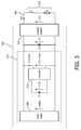
- Fig. 3 shows a simplified schematic diagram of a power chain such as the gradient amplifier power chain 203 for supplying a gradient coil 303.
- the power chain 301 is shown as having two outputs or connections 305 to the gradient coil 303.
- the power chain 301 comprises a power supply system 311, a gradient amplifier 307 and a supply capacitor C2 connected in parallel circuit.
- the supply capacitor C2 is configured to deliver peak power to the gradient coil 303. This is typically performed in a short time period of the order of 300 us. During that time period, an energy exchange between the energy stored in the supply capacitor (0.5 * C2 * U in 2 ) and the stored energy in the gradient coil L (0.5 * L * I out 2 ) may happen.
- the energy involved is relatively small, in the order of 100 - 200 J.
- the power supply system 311 comprises a power supply 309 and capacitor C1.
- the power supply 309 is adapted to supply a first voltage U supply to the gradient amplifier 307 for driving the gradient coil 303.
- the gradient amplifier output is connected to the gradient coil.
- Capacitor C1 is connected to the power supply 309 via the voltage converter 313 and it is configured to supply a second voltage U buffer to the gradient amplifier 307. In this way, more power than available from the power supply 309 can be delivered to the gradient amplifier for a limited time period.
- the voltage converter 313 is configured to control the second voltage U buffer as to compensate for a variation in the first voltage resulting from the driving of the gradient coil, for example, during waveforms where the power dissipation in the gradient coil 303 exceeds the power range of the power supply 309.
- the voltage converter 313 transforms the input voltage U buffer to the output voltage U converter while controlling the current I converter . In this way, the voltage U buffer across capacitor C1 is made independent of the voltage U in at the gradient amplifier 307 by the voltage converter 313.
- Capacitor C1 stores a substantial large amount of energy, in the order of 1 to 3 kJ. Its discharge time is much longer (up to 100 ms) than the discharge time of capacitor C2.
- the voltage converter 313 may be for example a DC-to-DC converter with controlled charge and discharge current. Depending on the required operating range of Uin (first voltage) and the voltage across capacitor C1 (second voltage), a buck-boost converter or a boost converter could be used as converter topologies, but other known topologies could be used as well. The advantage of using the voltage converter 313 will be further elaborated in detail with reference to Fig. 4 .
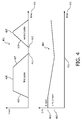
- Fig 4 shows the waveforms for the gradient current I out 401 and the first voltage U in 403 as function of time 421 for prior art systems without the voltage converter 313.
- Two subsequent gradient current pulses 405 and 407 are generated.
- the first one 405 has a high amplitude and high rising slope 409.
- the total power dissipation in the gradient coil 303 is higher than the available power from the power supply 309.
- the voltage U in drops while capacitors C1+C2 deliver energy to the gradient amplifier 307.
- the voltage U in is dropped to x% U nom 415 of its nominal value 413.
- the falling slope 417 of the first pulse 405 and the rising slope 419 of the second gradient current pulse 407 are limited because the gradient amplifier 307 has lower input voltage and consequently the maximum value of
- a fast rising slope at time 423 of the second gradient current pulse may be realized by a high input voltage U in at that time 423, which in turn may be realized by a large power range of the power supply and/or a large capacitance C1+C2 and/or a short duration of the first pulse.
- the capacitance C1+C2 needs to increase if a faster rising slope for the second gradient pulse is required.
- required capacitance C1+C2 and cost of these buffer capacitors are high for high x-values (i.e. at a low voltage drop) as described above. This is overcome by using the voltage converter 313.
- the present method splits up C1 and C2 and makes optimum use of the energy storage of C1, because the useful energy that can be delivered to the gradient amplifier 307 can be made independent of the allowed voltage drop.
- the voltage converter 313 is configured to control the second voltage as to compensate for this voltage drop.
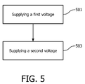
- Fig.5 is a flowchart for a method for supplying current to a gradient coil of a magnetic resonance imaging system by a gradient amplifier system.
- an electrical power supply supplies a first voltage to a gradient amplifier for driving the gradient coil.
- the gradient amplifier is connected in parallel to the gradient coil.
- a variation in the first voltage across the gradient coil resulting from the driving of the gradient coil due for example to internal resistance of the circuit may happen.
- a control unit may detect the variation in the first voltage and provide feedback so as the energy buffer supplies, in step 503, a second voltage to the gradient amplifier, such that to compensate for the variation.
- the second voltage is controlled by a voltage converter comprised in the energy buffer.
Landscapes
- Physics & Mathematics (AREA)
- Condensed Matter Physics & Semiconductors (AREA)
- General Physics & Mathematics (AREA)
- Engineering & Computer Science (AREA)
- Signal Processing (AREA)
- High Energy & Nuclear Physics (AREA)
- Magnetic Resonance Imaging Apparatus (AREA)
Applications Claiming Priority (2)
| Application Number | Priority Date | Filing Date | Title |
|---|---|---|---|
| US201261624481P | 2012-04-16 | 2012-04-16 | |
| PCT/IB2013/052695 WO2013156889A1 (en) | 2012-04-16 | 2013-04-04 | Mri gradient power system with add on energy buffer |
Publications (2)
| Publication Number | Publication Date |
|---|---|
| EP2839306A1 EP2839306A1 (en) | 2015-02-25 |
| EP2839306B1 true EP2839306B1 (en) | 2016-11-02 |
Family
ID=48576467
Family Applications (1)
| Application Number | Title | Priority Date | Filing Date |
|---|---|---|---|
| EP13726866.0A Not-in-force EP2839306B1 (en) | 2012-04-16 | 2013-04-04 | Mri gradient power system with add on energy buffer |
Country Status (6)
| Country | Link |
|---|---|
| US (1) | US9897672B2 (enExample) |
| EP (1) | EP2839306B1 (enExample) |
| JP (1) | JP5976920B2 (enExample) |
| CN (1) | CN104220891B (enExample) |
| RU (1) | RU2616773C2 (enExample) |
| WO (1) | WO2013156889A1 (enExample) |
Cited By (1)
| Publication number | Priority date | Publication date | Assignee | Title |
|---|---|---|---|---|
| US20150054509A1 (en) * | 2012-04-16 | 2015-02-26 | Koninklijke Philips N.V. | Mri gradient power system with add on energy buffer |
Families Citing this family (12)
| Publication number | Priority date | Publication date | Assignee | Title |
|---|---|---|---|---|
| DE102011086314B4 (de) * | 2011-11-14 | 2015-12-10 | Siemens Aktiengesellschaft | MRT-Anlage mit wenigstens einer Magnetspule und Verfahren zum Herstellen einer Schaltungsanordnung zum Schalten eines Spulenstroms |
| CN107106075B (zh) * | 2014-10-09 | 2020-06-30 | 通用电气公司 | 用于门驱动器单元中的非接触功率传输的方法和系统 |
| US10067203B2 (en) * | 2015-10-09 | 2018-09-04 | General Electric Company | Energy storage solution for an MRI system |
| CN107260327B (zh) | 2016-03-31 | 2021-01-05 | 通用电气公司 | 用于操控医疗成像装置的峰值功率要求的系统和方法 |
| JP7106252B2 (ja) * | 2017-06-26 | 2022-07-26 | キヤノンメディカルシステムズ株式会社 | 磁気共鳴イメージング装置 |
| CN107450040A (zh) * | 2017-07-11 | 2017-12-08 | 上海东软医疗科技有限公司 | 一种状态空间控制器及控制方法、梯度功率放大器 |
| EP3528000A1 (en) * | 2018-02-15 | 2019-08-21 | Koninklijke Philips N.V. | Rf transmit system with switchable power supply device |
| US10557901B2 (en) | 2018-02-21 | 2020-02-11 | General Electric Company | Systems and methods for providing gradient power for an MRI system |
| US10788551B2 (en) | 2018-05-30 | 2020-09-29 | General Electric Company | Synchronized control of power supply and gradient amplifier in MRI systems |
| EP3644084A1 (en) | 2018-10-23 | 2020-04-29 | Koninklijke Philips N.V. | Generation of rf pulses for mri applications |
| EP4211481A4 (en) * | 2020-09-08 | 2024-09-18 | Hyperfine Operations, Inc. | SYSTEMS AND METHODS FOR PROVIDING OPERATING POWER FOR A MAGNETIC RESONANCE IMAGING (MRI) SYSTEM |
| CN120143032A (zh) * | 2025-05-13 | 2025-06-13 | 华中科技大学同济医学院附属同济医院 | 一种磁共振射频线圈及其控制方法 |
Family Cites Families (16)
| Publication number | Priority date | Publication date | Assignee | Title |
|---|---|---|---|---|
| US5063349A (en) * | 1990-06-04 | 1991-11-05 | General Electric Company | Transformer-coupled gradient speed-up circuit |
| JP3431654B2 (ja) * | 1992-03-23 | 2003-07-28 | ゼネラル・エレクトリック・カンパニイ | 線形増幅器と直流電源の組み合わせを用いる勾配増幅システム |
| US5270657A (en) * | 1992-03-23 | 1993-12-14 | General Electric Company | Split gradient amplifier for an MRI system |
| RU2047871C1 (ru) * | 1992-12-23 | 1995-11-10 | Российский научный центр "Курчатовский институт" | Устройство магниторезонансного томографа |
| DE19511833C2 (de) * | 1995-03-30 | 1998-04-23 | Siemens Ag | Gradientenstromversorgung für ein Kernspintographiegerät |
| DE19511832C2 (de) | 1995-03-30 | 1997-01-30 | Siemens Ag | Verfahren und Vorrichtung zur Gradientenstromversorgung für ein Kernspintomographiegerät |
| DE19731690C2 (de) * | 1997-07-23 | 1999-10-28 | Siemens Ag | Leistungsverstärker und Kernspintomograph |
| US6552448B1 (en) | 1999-09-08 | 2003-04-22 | Harman International Industries, Incorporated | Energy management system for series connected amplifiers |
| CN1745315A (zh) * | 2003-02-03 | 2006-03-08 | 皇家飞利浦电子股份有限公司 | 具有多个输出电压电平的精确mri梯度放大器 |
| US7253625B2 (en) | 2003-02-03 | 2007-08-07 | Koninklijke Philips Electronics N.V. | Precision gradient amplifier with multiple output voltage levels |
| DE10353965A1 (de) | 2003-11-19 | 2005-06-09 | Siemens Ag | Verstärker mit endstufen-gesteuerter Regelung |
| JP5367293B2 (ja) * | 2008-03-31 | 2013-12-11 | ジーイー・メディカル・システムズ・グローバル・テクノロジー・カンパニー・エルエルシー | Mri装置 |
| EP2261685B1 (en) * | 2009-02-25 | 2012-09-26 | Bruker Biospin SA | Magnetic field gradient generating system and a method for reducing the noise level in NMR/MRI experiments |
| EP2839306B1 (en) * | 2012-04-16 | 2016-11-02 | Koninklijke Philips N.V. | Mri gradient power system with add on energy buffer |
| JP6472592B2 (ja) * | 2012-04-18 | 2019-02-20 | キヤノンメディカルシステムズ株式会社 | 磁気共鳴イメージング装置、及び、磁気共鳴イメージング方法 |
| JP6611589B2 (ja) * | 2015-12-17 | 2019-11-27 | キヤノンメディカルシステムズ株式会社 | 磁気共鳴イメージング装置 |
-
2013
- 2013-04-04 EP EP13726866.0A patent/EP2839306B1/en not_active Not-in-force
- 2013-04-04 CN CN201380019897.6A patent/CN104220891B/zh active Active
- 2013-04-04 WO PCT/IB2013/052695 patent/WO2013156889A1/en not_active Ceased
- 2013-04-04 US US14/394,643 patent/US9897672B2/en active Active
- 2013-04-04 JP JP2015505041A patent/JP5976920B2/ja not_active Expired - Fee Related
- 2013-04-04 RU RU2014145680A patent/RU2616773C2/ru not_active IP Right Cessation
Cited By (2)
| Publication number | Priority date | Publication date | Assignee | Title |
|---|---|---|---|---|
| US20150054509A1 (en) * | 2012-04-16 | 2015-02-26 | Koninklijke Philips N.V. | Mri gradient power system with add on energy buffer |
| US9897672B2 (en) * | 2012-04-16 | 2018-02-20 | Koninklijke Philips Electronics N.V. | MRI gradient power system with add on energy buffer |
Also Published As
| Publication number | Publication date |
|---|---|
| JP2015512737A (ja) | 2015-04-30 |
| RU2616773C2 (ru) | 2017-04-18 |
| EP2839306A1 (en) | 2015-02-25 |
| WO2013156889A1 (en) | 2013-10-24 |
| CN104220891A (zh) | 2014-12-17 |
| US20150054509A1 (en) | 2015-02-26 |
| CN104220891B (zh) | 2017-08-04 |
| US9897672B2 (en) | 2018-02-20 |
| RU2014145680A (ru) | 2016-06-10 |
| JP5976920B2 (ja) | 2016-08-24 |
Similar Documents
| Publication | Publication Date | Title |
|---|---|---|
| EP2839306B1 (en) | Mri gradient power system with add on energy buffer | |
| US7714583B2 (en) | Power supply for supplying multi-channel, stable, isolated DC power and method of making same | |
| EP3234623B1 (en) | A power device and method for driving a load | |
| US8278927B2 (en) | System and method for controlling current in gradient coil of magnetic resonance imaging system | |
| CN102484433B (zh) | 用于向负载供应电力的电源、方法和计算机程序产品 | |
| CN103261907B (zh) | 用于mri梯度线圈电源的在数字域中的状态空间反馈控制器 | |
| US5546299A (en) | Power supply for predominantly inductive loads | |
| US8947148B2 (en) | Hybrid analog/digital point-of-load controller | |
| CA2728337A1 (en) | Method and apparatus for power converter for class d audio power amplifiers | |
| US7253625B2 (en) | Precision gradient amplifier with multiple output voltage levels | |
| US10234519B2 (en) | Electric power converter and MRI system comprising such converter | |
| EP2877868A1 (en) | Mri gradient amplifier operable at different slew rates | |
| EP1595159A1 (en) | Precision gradient amplifier with multiple output voltage levels | |
| JPH0618565B2 (ja) | 変成器結合勾配高速化回路 | |
| US12466347B2 (en) | Active discharge of a vehicle intermediate circuit element using a discrete PWM pulse-generating discharge circuit | |
| JPH11155832A (ja) | 電力増幅器および核スピントモグラフ | |
| NL2022622B1 (en) | Electric power converter with inductively coupled parallel power stacks | |
| Babaloo et al. | Droop compensation of gradient current waveforms in gradient array systems | |
| US12494722B2 (en) | Magnetic resonance system and power supply device for pulsed load of magnetic resonance system | |
| KR102677677B1 (ko) | 다중 전력카드용 디지털 제어기를 포함하는 저전압 직류 전력변환 모듈 | |
| JP3741507B2 (ja) | 電源装置及びこれを用いた磁気共鳴イメージング装置 | |
| US11105872B2 (en) | Magnetic resonance imaging apparatus with enhanced image quality | |
| US20110227557A1 (en) | High-voltage switching hot-swap circuit | |
| WO2020054034A1 (ja) | スイッチング電源装置及びそれを用いた核磁気共鳴イメージング装置用電源装置 | |
| KR20130055284A (ko) | 입체 영상 적응형 디스플레이 구동 장치 |
Legal Events
| Date | Code | Title | Description |
|---|---|---|---|
| PUAI | Public reference made under article 153(3) epc to a published international application that has entered the european phase |
Free format text: ORIGINAL CODE: 0009012 |
|
| 17P | Request for examination filed |
Effective date: 20141117 |
|
| AK | Designated contracting states |
Kind code of ref document: A1 Designated state(s): AL AT BE BG CH CY CZ DE DK EE ES FI FR GB GR HR HU IE IS IT LI LT LU LV MC MK MT NL NO PL PT RO RS SE SI SK SM TR |
|
| AX | Request for extension of the european patent |
Extension state: BA ME |
|
| DAX | Request for extension of the european patent (deleted) | ||
| GRAP | Despatch of communication of intention to grant a patent |
Free format text: ORIGINAL CODE: EPIDOSNIGR1 |
|
| INTG | Intention to grant announced |
Effective date: 20160523 |
|
| GRAS | Grant fee paid |
Free format text: ORIGINAL CODE: EPIDOSNIGR3 |
|
| GRAA | (expected) grant |
Free format text: ORIGINAL CODE: 0009210 |
|
| AK | Designated contracting states |
Kind code of ref document: B1 Designated state(s): AL AT BE BG CH CY CZ DE DK EE ES FI FR GB GR HR HU IE IS IT LI LT LU LV MC MK MT NL NO PL PT RO RS SE SI SK SM TR |
|
| REG | Reference to a national code |
Ref country code: GB Ref legal event code: FG4D |
|
| REG | Reference to a national code |
Ref country code: AT Ref legal event code: REF Ref document number: 842375 Country of ref document: AT Kind code of ref document: T Effective date: 20161115 Ref country code: CH Ref legal event code: EP |
|
| REG | Reference to a national code |
Ref country code: IE Ref legal event code: FG4D |
|
| REG | Reference to a national code |
Ref country code: DE Ref legal event code: R096 Ref document number: 602013013490 Country of ref document: DE |
|
| REG | Reference to a national code |
Ref country code: DE Ref legal event code: R084 Ref document number: 602013013490 Country of ref document: DE |
|
| REG | Reference to a national code |
Ref country code: GB Ref legal event code: 746 Effective date: 20170105 |
|
| PG25 | Lapsed in a contracting state [announced via postgrant information from national office to epo] |
Ref country code: LV Free format text: LAPSE BECAUSE OF FAILURE TO SUBMIT A TRANSLATION OF THE DESCRIPTION OR TO PAY THE FEE WITHIN THE PRESCRIBED TIME-LIMIT Effective date: 20161102 |
|
| REG | Reference to a national code |
Ref country code: NL Ref legal event code: MP Effective date: 20161102 |
|
| REG | Reference to a national code |
Ref country code: LT Ref legal event code: MG4D |
|
| REG | Reference to a national code |
Ref country code: AT Ref legal event code: MK05 Ref document number: 842375 Country of ref document: AT Kind code of ref document: T Effective date: 20161102 |
|
| PG25 | Lapsed in a contracting state [announced via postgrant information from national office to epo] |
Ref country code: GR Free format text: LAPSE BECAUSE OF FAILURE TO SUBMIT A TRANSLATION OF THE DESCRIPTION OR TO PAY THE FEE WITHIN THE PRESCRIBED TIME-LIMIT Effective date: 20170203 Ref country code: NO Free format text: LAPSE BECAUSE OF FAILURE TO SUBMIT A TRANSLATION OF THE DESCRIPTION OR TO PAY THE FEE WITHIN THE PRESCRIBED TIME-LIMIT Effective date: 20170202 Ref country code: SE Free format text: LAPSE BECAUSE OF FAILURE TO SUBMIT A TRANSLATION OF THE DESCRIPTION OR TO PAY THE FEE WITHIN THE PRESCRIBED TIME-LIMIT Effective date: 20161102 Ref country code: NL Free format text: LAPSE BECAUSE OF FAILURE TO SUBMIT A TRANSLATION OF THE DESCRIPTION OR TO PAY THE FEE WITHIN THE PRESCRIBED TIME-LIMIT Effective date: 20161102 Ref country code: LT Free format text: LAPSE BECAUSE OF FAILURE TO SUBMIT A TRANSLATION OF THE DESCRIPTION OR TO PAY THE FEE WITHIN THE PRESCRIBED TIME-LIMIT Effective date: 20161102 |
|
| REG | Reference to a national code |
Ref country code: FR Ref legal event code: PLFP Year of fee payment: 5 |
|
| PG25 | Lapsed in a contracting state [announced via postgrant information from national office to epo] |
Ref country code: AT Free format text: LAPSE BECAUSE OF FAILURE TO SUBMIT A TRANSLATION OF THE DESCRIPTION OR TO PAY THE FEE WITHIN THE PRESCRIBED TIME-LIMIT Effective date: 20161102 Ref country code: FI Free format text: LAPSE BECAUSE OF FAILURE TO SUBMIT A TRANSLATION OF THE DESCRIPTION OR TO PAY THE FEE WITHIN THE PRESCRIBED TIME-LIMIT Effective date: 20161102 Ref country code: PL Free format text: LAPSE BECAUSE OF FAILURE TO SUBMIT A TRANSLATION OF THE DESCRIPTION OR TO PAY THE FEE WITHIN THE PRESCRIBED TIME-LIMIT Effective date: 20161102 Ref country code: PT Free format text: LAPSE BECAUSE OF FAILURE TO SUBMIT A TRANSLATION OF THE DESCRIPTION OR TO PAY THE FEE WITHIN THE PRESCRIBED TIME-LIMIT Effective date: 20170302 Ref country code: IS Free format text: LAPSE BECAUSE OF FAILURE TO SUBMIT A TRANSLATION OF THE DESCRIPTION OR TO PAY THE FEE WITHIN THE PRESCRIBED TIME-LIMIT Effective date: 20170302 Ref country code: RS Free format text: LAPSE BECAUSE OF FAILURE TO SUBMIT A TRANSLATION OF THE DESCRIPTION OR TO PAY THE FEE WITHIN THE PRESCRIBED TIME-LIMIT Effective date: 20161102 Ref country code: ES Free format text: LAPSE BECAUSE OF FAILURE TO SUBMIT A TRANSLATION OF THE DESCRIPTION OR TO PAY THE FEE WITHIN THE PRESCRIBED TIME-LIMIT Effective date: 20161102 Ref country code: HR Free format text: LAPSE BECAUSE OF FAILURE TO SUBMIT A TRANSLATION OF THE DESCRIPTION OR TO PAY THE FEE WITHIN THE PRESCRIBED TIME-LIMIT Effective date: 20161102 |
|
| PG25 | Lapsed in a contracting state [announced via postgrant information from national office to epo] |
Ref country code: CZ Free format text: LAPSE BECAUSE OF FAILURE TO SUBMIT A TRANSLATION OF THE DESCRIPTION OR TO PAY THE FEE WITHIN THE PRESCRIBED TIME-LIMIT Effective date: 20161102 Ref country code: EE Free format text: LAPSE BECAUSE OF FAILURE TO SUBMIT A TRANSLATION OF THE DESCRIPTION OR TO PAY THE FEE WITHIN THE PRESCRIBED TIME-LIMIT Effective date: 20161102 Ref country code: DK Free format text: LAPSE BECAUSE OF FAILURE TO SUBMIT A TRANSLATION OF THE DESCRIPTION OR TO PAY THE FEE WITHIN THE PRESCRIBED TIME-LIMIT Effective date: 20161102 Ref country code: SK Free format text: LAPSE BECAUSE OF FAILURE TO SUBMIT A TRANSLATION OF THE DESCRIPTION OR TO PAY THE FEE WITHIN THE PRESCRIBED TIME-LIMIT Effective date: 20161102 Ref country code: RO Free format text: LAPSE BECAUSE OF FAILURE TO SUBMIT A TRANSLATION OF THE DESCRIPTION OR TO PAY THE FEE WITHIN THE PRESCRIBED TIME-LIMIT Effective date: 20161102 |
|
| REG | Reference to a national code |
Ref country code: DE Ref legal event code: R097 Ref document number: 602013013490 Country of ref document: DE |
|
| PG25 | Lapsed in a contracting state [announced via postgrant information from national office to epo] |
Ref country code: IT Free format text: LAPSE BECAUSE OF FAILURE TO SUBMIT A TRANSLATION OF THE DESCRIPTION OR TO PAY THE FEE WITHIN THE PRESCRIBED TIME-LIMIT Effective date: 20161102 Ref country code: BE Free format text: LAPSE BECAUSE OF FAILURE TO SUBMIT A TRANSLATION OF THE DESCRIPTION OR TO PAY THE FEE WITHIN THE PRESCRIBED TIME-LIMIT Effective date: 20161102 Ref country code: SM Free format text: LAPSE BECAUSE OF FAILURE TO SUBMIT A TRANSLATION OF THE DESCRIPTION OR TO PAY THE FEE WITHIN THE PRESCRIBED TIME-LIMIT Effective date: 20161102 Ref country code: BG Free format text: LAPSE BECAUSE OF FAILURE TO SUBMIT A TRANSLATION OF THE DESCRIPTION OR TO PAY THE FEE WITHIN THE PRESCRIBED TIME-LIMIT Effective date: 20170202 |
|
| PLBE | No opposition filed within time limit |
Free format text: ORIGINAL CODE: 0009261 |
|
| STAA | Information on the status of an ep patent application or granted ep patent |
Free format text: STATUS: NO OPPOSITION FILED WITHIN TIME LIMIT |
|
| 26N | No opposition filed |
Effective date: 20170803 |
|
| PG25 | Lapsed in a contracting state [announced via postgrant information from national office to epo] |
Ref country code: SI Free format text: LAPSE BECAUSE OF FAILURE TO SUBMIT A TRANSLATION OF THE DESCRIPTION OR TO PAY THE FEE WITHIN THE PRESCRIBED TIME-LIMIT Effective date: 20161102 |
|
| REG | Reference to a national code |
Ref country code: CH Ref legal event code: PL |
|
| REG | Reference to a national code |
Ref country code: IE Ref legal event code: MM4A |
|
| PG25 | Lapsed in a contracting state [announced via postgrant information from national office to epo] |
Ref country code: MC Free format text: LAPSE BECAUSE OF FAILURE TO SUBMIT A TRANSLATION OF THE DESCRIPTION OR TO PAY THE FEE WITHIN THE PRESCRIBED TIME-LIMIT Effective date: 20161102 |
|
| PG25 | Lapsed in a contracting state [announced via postgrant information from national office to epo] |
Ref country code: CH Free format text: LAPSE BECAUSE OF NON-PAYMENT OF DUE FEES Effective date: 20170430 Ref country code: LI Free format text: LAPSE BECAUSE OF NON-PAYMENT OF DUE FEES Effective date: 20170430 Ref country code: LU Free format text: LAPSE BECAUSE OF NON-PAYMENT OF DUE FEES Effective date: 20170404 |
|
| PG25 | Lapsed in a contracting state [announced via postgrant information from national office to epo] |
Ref country code: IE Free format text: LAPSE BECAUSE OF NON-PAYMENT OF DUE FEES Effective date: 20170404 |
|
| REG | Reference to a national code |
Ref country code: FR Ref legal event code: PLFP Year of fee payment: 6 |
|
| PG25 | Lapsed in a contracting state [announced via postgrant information from national office to epo] |
Ref country code: MT Free format text: LAPSE BECAUSE OF NON-PAYMENT OF DUE FEES Effective date: 20170404 |
|
| PG25 | Lapsed in a contracting state [announced via postgrant information from national office to epo] |
Ref country code: HU Free format text: LAPSE BECAUSE OF FAILURE TO SUBMIT A TRANSLATION OF THE DESCRIPTION OR TO PAY THE FEE WITHIN THE PRESCRIBED TIME-LIMIT; INVALID AB INITIO Effective date: 20130404 |
|
| PG25 | Lapsed in a contracting state [announced via postgrant information from national office to epo] |
Ref country code: CY Free format text: LAPSE BECAUSE OF FAILURE TO SUBMIT A TRANSLATION OF THE DESCRIPTION OR TO PAY THE FEE WITHIN THE PRESCRIBED TIME-LIMIT Effective date: 20161102 |
|
| PG25 | Lapsed in a contracting state [announced via postgrant information from national office to epo] |
Ref country code: MK Free format text: LAPSE BECAUSE OF FAILURE TO SUBMIT A TRANSLATION OF THE DESCRIPTION OR TO PAY THE FEE WITHIN THE PRESCRIBED TIME-LIMIT Effective date: 20161102 |
|
| PG25 | Lapsed in a contracting state [announced via postgrant information from national office to epo] |
Ref country code: TR Free format text: LAPSE BECAUSE OF FAILURE TO SUBMIT A TRANSLATION OF THE DESCRIPTION OR TO PAY THE FEE WITHIN THE PRESCRIBED TIME-LIMIT Effective date: 20161102 |
|
| PG25 | Lapsed in a contracting state [announced via postgrant information from national office to epo] |
Ref country code: AL Free format text: LAPSE BECAUSE OF FAILURE TO SUBMIT A TRANSLATION OF THE DESCRIPTION OR TO PAY THE FEE WITHIN THE PRESCRIBED TIME-LIMIT Effective date: 20161102 |
|
| PGFP | Annual fee paid to national office [announced via postgrant information from national office to epo] |
Ref country code: DE Payment date: 20200430 Year of fee payment: 8 Ref country code: FR Payment date: 20200429 Year of fee payment: 8 |
|
| PGFP | Annual fee paid to national office [announced via postgrant information from national office to epo] |
Ref country code: GB Payment date: 20200429 Year of fee payment: 8 |
|
| REG | Reference to a national code |
Ref country code: DE Ref legal event code: R119 Ref document number: 602013013490 Country of ref document: DE |
|
| GBPC | Gb: european patent ceased through non-payment of renewal fee |
Effective date: 20210404 |
|
| PG25 | Lapsed in a contracting state [announced via postgrant information from national office to epo] |
Ref country code: FR Free format text: LAPSE BECAUSE OF NON-PAYMENT OF DUE FEES Effective date: 20210430 Ref country code: GB Free format text: LAPSE BECAUSE OF NON-PAYMENT OF DUE FEES Effective date: 20210404 Ref country code: DE Free format text: LAPSE BECAUSE OF NON-PAYMENT OF DUE FEES Effective date: 20211103 |