EP2839189B1 - Getriebe mit einer ersten welle, insbesondere abtreibenden welle, und einer zweiten welle, insbesondere zwischenwelle - Google Patents
Getriebe mit einer ersten welle, insbesondere abtreibenden welle, und einer zweiten welle, insbesondere zwischenwelle Download PDFInfo
- Publication number
- EP2839189B1 EP2839189B1 EP13715606.3A EP13715606A EP2839189B1 EP 2839189 B1 EP2839189 B1 EP 2839189B1 EP 13715606 A EP13715606 A EP 13715606A EP 2839189 B1 EP2839189 B1 EP 2839189B1
- Authority
- EP
- European Patent Office
- Prior art keywords
- shaft
- housing part
- transmission according
- holes
- sealing part
- Prior art date
- Legal status (The legal status is an assumption and is not a legal conclusion. Google has not performed a legal analysis and makes no representation as to the accuracy of the status listed.)
- Active
Links
Images


Classifications
-
- F—MECHANICAL ENGINEERING; LIGHTING; HEATING; WEAPONS; BLASTING
- F16—ENGINEERING ELEMENTS AND UNITS; GENERAL MEASURES FOR PRODUCING AND MAINTAINING EFFECTIVE FUNCTIONING OF MACHINES OR INSTALLATIONS; THERMAL INSULATION IN GENERAL
- F16H—GEARING
- F16H57/00—General details of gearing
- F16H57/02—Gearboxes; Mounting gearing therein
- F16H57/029—Gearboxes; Mounting gearing therein characterised by means for sealing the gearboxes, e.g. to improve airtightness
-
- F—MECHANICAL ENGINEERING; LIGHTING; HEATING; WEAPONS; BLASTING
- F16—ENGINEERING ELEMENTS AND UNITS; GENERAL MEASURES FOR PRODUCING AND MAINTAINING EFFECTIVE FUNCTIONING OF MACHINES OR INSTALLATIONS; THERMAL INSULATION IN GENERAL
- F16H—GEARING
- F16H57/00—General details of gearing
- F16H57/02—Gearboxes; Mounting gearing therein
- F16H57/031—Gearboxes; Mounting gearing therein characterised by covers or lids for gearboxes
-
- F—MECHANICAL ENGINEERING; LIGHTING; HEATING; WEAPONS; BLASTING
- F16—ENGINEERING ELEMENTS AND UNITS; GENERAL MEASURES FOR PRODUCING AND MAINTAINING EFFECTIVE FUNCTIONING OF MACHINES OR INSTALLATIONS; THERMAL INSULATION IN GENERAL
- F16H—GEARING
- F16H57/00—General details of gearing
- F16H57/02—Gearboxes; Mounting gearing therein
- F16H2057/02039—Gearboxes for particular applications
- F16H2057/02069—Gearboxes for particular applications for industrial applications
Definitions
- the invention relates to a transmission with a first shaft, in particular an output shaft, and a second shaft, in particular intermediate shaft.
- a gear has an input shaft, on which a toothing rotatably connected with it is provided which engages with a gear rotatably connected to an intermediate shaft, wherein the intermediate shaft has a further toothing also rotatably connected thereto, which is in engagement with a drive shaft of the transmission rotatably connected to the output shaft.
- the invention is therefore the object of developing a transmission, the cleaning should be simple and effective executable.
- the cover is executable rounded on its outside, so that water and / or liquid detergent flows quickly.
- parts or components can be covered, which have a fissured surface structure, such as the shrink disc with the provided screws and / or nuts, the shaft seal or a cap having a substantially planar surface and at the transition region to the housing part having circumferential gap or a circumferential recess.
- the cover is thus tightly connected to the housing part and allowed in its interior rugged components that can cause an accumulation of water or liquid depending on the mounting direction of the transmission.
- Such an accumulation of liquid for example sugar-containing solutions, is effected in particular by depressions, such as gap regions or grooves, or else by essentially flat or concave surface regions.
- the cover can be executed in such a way that it is arched in such a way, for example in the shape of a spherical segment or in sections in an oval shape, so that liquid is present in each case Mounting direction of the transmission drains and / or drips and thus accumulations are prevented.
- a sealing part is provided, which is flat and has an oval outer contour.
- a recess is providable, so that the fissured surface portions of the parts protrude through the recess and protrude into the interior formed by the cover.
- the sealing member thus has the essential function of producing the tightness between the cover and the housing part.
- a direct covering of the cap is allowed, as this substantially flat adjoins the surrounding surface portions of the housing part.
- one of the cover hood is arranged a collar section, so that the pressure load can be reduced by the collar section having a correspondingly large area.
- the collar portion extends substantially parallel to that surface portion of the housing part in which the collar portion presses the sealing part against the surface portion of the housing part.
- the cover is preferably manufactured as a plastic injection molded part.
- the first shaft is a hollow shaft and the second shaft is a solid shaft.
- a solid shaft of a device to be driven can be inserted into the hollow shaft and frictionally connected thereto, in particular by means of the shrink disk, which shrinks a shaft portion of the hollow shaft to this solid shaft.
- the formation of the second wave as a solid shaft allows the transmission of high torques.
- the closure cap covers a bearing of the second shaft and / or a shaft seal arranged on the second shaft.
- the closure cap forms with an edge region of the outer surface of the housing part surrounding the second recess in the Essentially flat area section.
- hood portion is executable rounded for discharging liquid and the collar portion reduces the contact pressure to an acceptable level.
- the hood portion is rotationally symmetrical.
- the advantage here is that a simple production is possible.
- a torque support member is attached to the housing part, in particular screw-connected, wherein between the torque-supporting part and the housing part a sealing part, in particular a sealing part which is similar to the first-mentioned sealing part, is arranged.
- the collar portion presses the sealing member on the cap, so that it is covered by the sealing part and / or the collar portion.
- the advantage here is that the sealing member is used in various applications on the transmission, namely on the one hand for sealing between the cover and the housing part and on the other hand for sealing between torque support member and housing part.
- the sealing part arranged between the torque-supporting part and the housing part is similar to the sealing part which is arranged between the covering hood and the housing part.
- the advantage here is that the seal parts are similar executable and thus only one type seal part in the warehouse of the manufacturing plant must be stored.
- the sealing part is made of an elastic material, such as rubber or plastic and / or the cover is made of plastic or metal, in particular steel or aluminum, and the housing part made of metal, in particular steel or aluminum, is made.
- the cover is made of a less elastic material than the sealing part and thus a simple sealing can be achieved.
- the torque-supporting part has a lever-like extension or section which extends in the direction of the pointed part of the oval.
- the torque support member has the same radial outer contour as the cover at least in sections. In the other sections, the torque support member projects beyond the seal member in the radial direction. In this way, the radial outer edge of the torque support member and the cover is equally coverable and sealable.
- FIG. 2 is a plan view with the cover removed 1 shown.
- FIG. 3 an associated cross section is shown.
- FIG. 5 the cover 1 is shown in side view.
- a sealing member 61 is shown in an oblique view, which is arranged between the cover 1 and the housing part 2.
- a cover 1 is arranged on the transmission, which covers the axial end portion of a hollow shaft 30.
- a driven solid shaft is inserted into the hollow shaft 30 and connected to a shrink disk 21.
- the hollow shaft 30 is preferably the driven shaft of the transmission.
- the cover 1 thus covers the otherwise outstanding shrink disc 21, which causes the frictional connection between the solid shaft and the hollow shaft 30.
- the cover 1 is tightly connected by means of an intermediate between the housing part 2 of the transmission and the cover 1 sealing part 61.
- the cover is screwed by means of screws 3 to the housing part 2.
- the sealing part between the cover 1 and the housing part is squeezed, whereby the seal is effected.
- the sealing member 61 is made of an elastic material, in particular of a more elastic material than the material of the cover 1 and as the material of the housing part.
- a rubber or an elastic plastic is used as the material of the sealing part 61.
- a shaft seal 73 is provided, which is arranged between the hollow shaft and the housing part and thus also covered by the cover 1.
- the cover 1 has a non-circular shape and thus also covers a closure cap 22 for closing an opening in the housing part 2. This opening is used to insert an intermediate shaft, which is mounted on a bearing in the housing part.
- the closure cap which is preferably made of a plastic or rubber, covers the axial end region and / or the bearing of an intermediate shaft of the transmission.
- the screws 3 are circumferentially spaced around the axis of the hollow shaft 30 around each other regularly.
- a not centrally arranged screw 4 is arranged on the side facing away from the screws 3 side of the cap 22.
- FIG. 2 is the side view of the transmission with the cover removed 1 and removed seal member 61 shown.
- the hole pattern of the threaded holes 20 for receiving screws 3 is shown, with more threaded holes 20 are available as screws.
- the hollow shaft 30 is mounted via bearings 31 in the housing part 2 and sealed by means of the shaft seal 73 against the housing part 2.
- the cover 1 has a hood portion 42 and a collar portion 41.
- the substantially planar collar portion 41 rests against the sealing member 61, which is likewise planar, and which is interposed between the housing part 2 and the covering hood 1.
- the collar portion 41 has through holes, so through holes 40, through which the screws (3, 4) protrude, wherein the sealing member 61 corresponding corresponding holes, so that the screws (3, 4) also project through the sealing member.
- the screw head of the screws (3, 4) abuts against the outside of the collar portion 41 and thus presses the cover 1 via the sealing member 61 to the housing part 2 by the threaded portion of the screws (3, 4) in a respective threaded bore 20 of the housing part 2 is screwed.
- the collar portion 41 is not circular on its outer periphery but substantially oval, wherein the more pointed part of the oval covering the cap 22 and the blunt part of the oval the shaft seal 73 and the shrink disc 21 and the hollow shaft 30th
- the hood portion 42 itself is rotationally symmetrical executable because the hood portion 42, the shrink disc 21 and the hollow shaft 30 and the shaft seal 73 covers, but air is interposed for spacing between these parts and the inner wall of the hood portion 42.
- the seal member 61 in this case has a circular recess on, so that air is interposed directly between the inner wall of the hood portion 42 and said parts, such as shrink disk 21st
- the collar portion 41 with the associated portion of the sealing part 61 which is interposed between the collar portion 41 and the housing part 1 covers the closure cap 22, wherein the sealing member 61 contacts the closure cap 22, because the Seal member 61 is made flat and also just executed collar portion 41 is pressed onto the seal member.
- a torque support member 70 is arranged on the side facing away from the cover 1 axial end portion of the hollow shaft 30 .
- the housing part 2 is arranged axially between the cover 1 and the torque-supporting part 70.
- the torque support member 70 is screwed by means of screws 71 to the housing part 2, wherein in turn a sealing member 61 is arranged, which is identical to the above-mentioned sealing member 61.
- the sealing member 61 on a hole pattern, which holes for the screws 71 and the screws (3, 4) is provided.
- the holes in the circumferential direction are regularly spaced from each other and arranged at the same radial distance from the axis of the hollow shaft 30. Only the screw 4 is seated on a different radial distance and a not assignable to the regularity circumferential angular position.
- the torque support member 70 is screwed by means of six screws 71 and the cover 1 by means of four screws 3 and a screw 4th
- the torque support member 70 is designed like a lever and has a hole 72, with which the torque support member to a fixed part of the system, such as nozzle, carrier, machine linkage or to a wall, can be fixed, in particular screwed.
- the sealing member 61 rests completely on the housing part 2 and on the torque-supporting part 70.
- the lever portion of the torque support member 70 thus extends in the direction of the more pointed portion of the oval outer shape, which in turn covers a cap 80.
- the screws 71 are screwed into threaded bores 82 of the housing part and the closure cap 80, which is the opening in the gear housing part 2 for the other Shaft end of the intermediate shaft and their bearings covers. In this case, the sealing member 61 is also touching on the cap 80.
- the hollow shaft 30 together with the bearing and optionally also an associated shaft sealing ring 73 are tightly covered.
Landscapes
- Engineering & Computer Science (AREA)
- General Engineering & Computer Science (AREA)
- Mechanical Engineering (AREA)
- General Details Of Gearings (AREA)
- Sealing Devices (AREA)
Description
- Die Erfindung betrifft ein Getriebe mit einer ersten Welle, insbesondere abtreibenden Welle, und einer zweiten Welle, insbesondere Zwischenwelle.
- Es ist allgemein bekannt, dass ein Getriebe eine eintreibende Welle aufweist, auf der eine mit ihr drehfest verbundene Verzahnung vorgesehen ist, die mit einer mit einer Zwischenwelle drehfest verbundenen Verzahnung im Eingriff steht, wobei die Zwischenwelle eine mit ihr ebenfalls drehfest verbundene weitere Verzahnung aufweist, welche mit einer mit einer Abtriebswelle des Getriebes drehfest verbundenen Abtriebswelle im Eingriff steht.
- Aus der gattungsgemässen
WO 2010/081523 A1 ist ein Getriebe mit Getriebegehäuse bekannt, wobei eine Zwischenscheibe (dortiges Bezugszeichen 24) eine Ausnehmung (dortiges Bezugszeichen 34) verdeckt. - Aus der
DE 10 2005 031197 A1 ist ein Antrieb mit Lüfter bekannt. - Aus der
US 2006/156861 A1 ist ein Getriebegehäuse bekannt. - Der Erfindung liegt daher die Aufgabe zugrunde, ein Getriebe weiterzubilden, wobei die Reinigung einfach und effektiv ausführbar sein soll.
- Erfindungsgemäß wird die Aufgabe bei dem Getriebe nach den in Anspruch 1 angegebenen Merkmalen gelöst.
- Von Vorteil ist dabei, dass die Abdeckhaube an ihrer Außenseite abgerundet ausführbar ist, so dass Wasser und/oder flüssiges Reinigungsmittel schnell abfließt. Insbesondere sind auf diese Weise Teile oder Komponenten abdeckbar, die eine zerklüftete Oberflächenstruktur aufweisen, wie beispielswiese die Schrumpfscheibe mit der an ihr vorgesehenen Schrauben und/oder Muttern, der Wellendichtring oder eine Verschlusskappe, die eine im Wesentlichen ebene Oberfläche aufweist und beim Übergangsbereich zum Gehäuseteil ein umlaufender Spalt oder eine umlaufende Vertiefung aufweist. Die Abdeckhaube wird also dicht mit dem Gehäuseteil verbunden und erlaubt in ihrem Innenbereich zerklüftete Komponenten, die abhängig von der Montagerichtung des Getriebes eine Ansammlung von Wasser oder Flüssigkeit bewirken können. Eine solche Ansammlung von Flüssigkeit, beispielsweise zuckerhaltige Lösungen, wird insbesondere durch Vertiefungen, wie Spaltbereiche oder Nuten, bewirkt oder auch durch im Wesentlichen ebene oder konkave Oberflächenbereiche.
- Die Abdeckhaube ist derart ausführbar, dass sie derart gewölbt ist, beispielsweise kugelabschnittsförmig oder abschnittsweise ovalförmig, so dass Flüssigkeit bei jeder Montagerichtung des Getriebes abfließt und/oder abtropft und somit Ansammlungen verhindert sind.
- Zur dichten Verbindung ist ein Dichtungsteil vorgesehen, das eben ausgeformt ist und eine ovale Außenkontur aufweist. Dabei ist eine Ausnehmung vorsehbar, so dass die zerklüfteten Oberflächenabschnitte der Teile durch die Ausnehmung hindurchragen und in den von der Abdeckhaube gebildeten Innenraum hineinragen. Das Dichtungsteil hat also die wesentliche Funktion des Herstellens der Dichtheit zwischen der Abdeckhaube und dem Gehäuseteil. Zusätzlich ist auch ein direktes Abdecken der Verschlusskappe erlaubt, da diese im Wesentlichen eben anschließt an die umgebenden Oberflächenabschnitte des Gehäuseteils.
- Zum Anpressen des Dichtungsteils an das Gehäuseteil ist ein der Abdeckhaube ein Kragenabschnitt angeordnet, so dass die Druckbelastung reduzierbar ist, indem der Kragenabschnitt eine entsprechend große Fläche aufweist. Der Kragenabschnitt verläuft im Wesentlichen parallel zu demjenigen Oberflächenabschnitt des Gehäuseteils, in welchem der Kragenabschnitt das Dichtungsteil an den Oberflächenabschnitt des Gehäuseteils andrückt.
- Die Abdeckhaube ist vorzugsweise als Kunststoffspritzgussteil fertigbar.
- Bei einer vorteilhaften Ausgestaltung ist die erste Welle eine Hohlwelle und die zweite Welle ist eine Vollwelle. Von Vorteil ist dabei, dass eine Vollwelle einer anzutreibenden Vorrichtung in die Hohlwelle einsteckbar ist und mit dieser kraftschlüssig verbindbar ist, insbesondere mittels der Schrumpfscheibe, welche einen Wellenabschnitt der Hohlwelle auf diese Vollwelle aufschrumpft. Die Ausbildung der zweiten Welle als Vollwelle ermöglicht die Übertragung hoher Drehmomente.
- Bei einer vorteilhaften Ausgestaltung deckt die Verschlusskappe ein Lager der zweiten Welle und/oder einen an der zweiten Welle angeordneten Wellendichtring ab. Von Vorteil ist dabei, dass somit eine öldichte Abdichtung schon durch die Verschlusskappe bewirkt ist und daher die Abdeckhaube nur eine gegen Wasser oder Reinigungsmittel dichte Abdeckung bereit stellen muss.
- Bei einer vorteilhaften Ausgestaltung bildet die Verschlusskappe mit einem die zweite Ausnehmung umgebenden Randbereich der Außenoberfläche des Gehäuseteils einen im Wesentlichen ebenen Flächenabschnitt. Von Vorteil ist dabei, dass eine direkte Abdeckung durch das Dichtungsteil ermöglicht ist.
- Von Vorteil ist dabei, dass der Haubenabschnitt abgerundet ausführbar ist zum Abführen von Flüssigkeit und der Kragenabschnitt den Anpressdruck auf ein zulässiges Maß reduziert.
- Bei einer vorteilhaften Ausgestaltung ist der Haubenabschnitt rotationssymmetrisch ausgeführt. Von Vorteil ist dabei, dass eine einfache Herstellung ermöglicht ist.
- Bei einer vorteilhaften Ausgestaltung ist ein Drehmomentstützteil am Gehäuseteil befestigt, insbesondere schraubverbunden ist,
wobei zwischen Drehmomentstützteil und Gehäuseteil ein Dichtungsteil, insbesondere ein zum erstgenannten Dichtungsteil gleichartiges Dichtungsteil, angeordnet ist. Von Vorteil ist dabei, dass im Lager nur eine Sorte Dichtungsteile bevorratet werden muss. - Bei einer vorteilhaften Ausgestaltung weist das Dichtungsteil ein Lochbild auf,
wobei bei Anordnung des Dichtungsteils zwischen Abdeckhaube und Gehäuseteil Schrauben durch erste Löcher, insbesondere des Lochbilds, des Dichtungsteils hindurchragen,
wobei bei Anordnung des Dichtungsteils zwischen Drehmomentstützteil und Gehäuseteil Schrauben durch zweite Löcher, insbesondere des Lochbilds, des Dichtungsteils hindurchragen, - wobei die Anzahl der ersten Löcher und die Anzahl der zweiten Löcher unterschiedlich ist
- oder wobei die Menge der Winkelpositionen der ersten Löcher sich unterscheidet von der Menge der Winkelpositionen der zweiten Löcher. Von Vorteil ist dabei, dass
- Bei einer vorteilhaften Ausgestaltung drückt der Kragenabschnitt das Dichtungsteil auf die Verschlusskappe, so dass diese vom Dichtungsteil und/oder vom Kragenabschnitt abdeckt ist. Von Vorteil ist dabei, dass das Dichtungsteil in verschiedener Verwendung einsetzbar ist am Getriebe, nämlich einerseits zum Abdichten zwischen Abdeckhaube und Gehäuseteil und andererseits zum Abdichten zwischen Drehmomentstützteil und Gehäuseteil.
- Bei einer vorteilhaften Ausgestaltung gleicht das zwischen Drehmomentstützteil und Gehäuseteil angeordnete Dichtungsteil demjenigen Dichtungsteil, welches zwischen Abdeckhaube und Gehäuseteil angeordnet ist. Von Vorteil ist dabei, dass die Dichtungsteile gleichartig ausführbar sind und somit nur eine Sorte Dichtungsteil im Lager der Herstellungsanlage bevorratet werden muss.
- Bei einer vorteilhaften Ausgestaltung ist das Dichtungsteil aus einem elastischen Stoff, wie Gummi oder Kunststoff, gefertigt
und/oder die Abdeckhaube ist aus Kunststoff oder Metall, insbesondere Stahl oder Aluminium, gefertigt und das Gehäuseteil aus Metall, insbesondere Stahl oder Aluminium, gefertigt ist. Von Vorteil ist dabei, dass die Abdeckhaube aus einem weniger elastischen Material als das Dichtungsteil fertigbar ist und somit ein einfaches Abdichten erreichbar ist. - Bei einer vorteilhaften Ausgestaltung weist das Drehmomentstützteil einen hebelartigen Fortsatz oder Abschnitt auf, der in Richtung des spitzen Teils des Ovals sich erstreckt. Von Vorteil ist dabei, dass das Drehmomentstützteil dieselbe radiale Außenkontur wie die Abdeckhaube zumindest abschnittsweise aufweist. In den anderen Abschnitten ragt das Drehmomentstützteil über das Dichtungsteil in radialer Richtung hinaus. Auf diese Weise ist der radiale Außenrand des Drehmomentstützteils und der Abdeckhaube gleichermaßen abdeckbar und abdichtbar.
- Weitere Vorteile ergeben sich aus den Unteransprüchen. Die Erfindung ist nicht auf die Merkmalskombination der Ansprüche beschränkt. Für den Fachmann ergeben sich weitere sinnvolle Kombinationsmöglichkeiten von Ansprüchen und/oder einzelnen Anspruchsmerkmalen und/oder Merkmalen der Beschreibung und/oder der Figuren, insbesondere aus der Aufgabenstellung und/oder der sich durch Vergleich mit dem Stand der Technik stellenden Aufgabe.
- Die Erfindung wird nun anhand von Abbildungen näher erläutert:
- In der
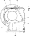
Figur 1 ist eine Draufsicht auf ein erfindungsgemäßes Getriebe mit einer Abdeckhaube 1 gezeigt. - In der
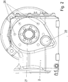
Figur 2 ist eine Draufsicht bei entfernter Abdeckhaube 1 gezeigt. - In der
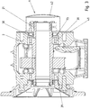
Figur 3 ist ein zugehöriger Querschnitt gezeigt. - In der
Figur 4 ist die Abdeckhaube 1 in Schrägansicht gezeigt. - In der
Figur 5 ist die Abdeckhaube 1 in Seitenansicht gezeigt. - In der
Figur 6 ist ein Dichtungsteil 61 in Schrägansicht gezeigt, welches zwischen Abdeckhaube 1 und Gehäuseteil 2 angeordnet ist. - In der
Figur 7 ist das Getriebe aus einer gegenüber liegenden Seitenansicht gezeigt, so dass die Drehmomentstütze 70 sichtbar ist. - In der
Figur 8 ist dieselbe Seitenansicht bei entfernter Drehmomentstütze 70 gezeigt. - Wie in
Figur 1 gezeigt, ist an dem Getriebe eine Abdeckhaube 1 angeordnet, welche den axialen Endbereich einer Hohlwelle 30 abdeckt. - An ihrem von der Abdeckhaube 1 abgewandten axialen Endbereich wird eine anzutreibenden Vollwelle in die Hohlwelle 30 eingesteckt und mit einer Schrumpfscheibe 21 verbunden.
- Die Hohlwelle 30 ist vorzugsweise die abtreibende Welle des Getriebes.
- Die Abdeckhaube 1 deckt somit auch die ansonsten herausragende Schrumpfscheibe 21 ab, welche die kraftschlüssige Verbindung zwischen Vollwelle und Hohlwelle 30 bewirkt.
- Die Abdeckhaube 1 ist mittels einem zwischen dem Gehäuseteil 2 des Getriebes und der Abdeckhaube 1 zwischengeordneten Dichtungsteil 61 dicht verbunden.
- Die Abdeckhaube ist mittels Schrauben 3 an das Gehäuseteil 2 angeschraubt. Dabei wird das Dichtungsteil zwischen der Abdeckhaube 1 und dem Gehäuseteil gequetscht, wodurch die Abdichtung bewirkt wird. Denn das Dichtungsteil 61 ist aus einem elastischen Material, insbesondere aus einem elastischeren Material als das Material der Abdeckhaube 1 und als das Material des Gehäuseteils. Vorzugsweise wird als Material des Dichtungsteils 61 ein Gummi oder ein elastischer Kunststoff verwendet.
- Zur Abdichtung des im Getriebeinneren sich befindenden Schmieröls ist ein Wellendichtring 73 vorgesehen, welcher zwischen der Hohlwelle und dem Gehäuseteil angeordnet ist und somit ebenfalls von der Abdeckhaube 1 abgedeckt wird.
- Die Abdeckhaube 1 weist eine nicht kreisrunde Form auf und deckt somit auch eine Verschlusskappe 22 zum Verschließen einer Öffnung im Gehäuseteil 2 ab. Diese Öffnung dient zum Einführen einer Zwischenwelle, die über ein Lager im Gehäuseteil gelagert ist. Somit deckt die Verschlusskappe, welche vorzugsweise aus einem Kunststoff oder Gummi gefertigt ist, den axialen Endbereich und/oder das Lager einer Zwischenwelle des Getriebes ab.
- Die Schrauben 3 sind in Umfangsrichtung um die Achse der Hohlwelle 30 herum regelmäßig voneinander beabstandet.
- Eine nicht zentrisch angeordnete Schraube 4 ist auf der von den Schrauben 3 abgewandten Seite der Verschlusskappe 22 angeordnet.
- In
Figur 2 ist die Seitenansicht des Getriebes bei entfernter Abdeckhaube 1 und entferntem Dichtungsteil 61 gezeigt. Dabei ist auch das Lochbild der Gewindebohrungen 20 zur Aufnahme von Schrauben 3 gezeigt, wobei mehr Gewindebohrungen 20 vorhanden sind als Schrauben 3. - Wie in
Figur 3 gezeigt, ist die Hohlwelle 30 über Lager 31 im Gehäuseteil 2 gelagert und mittels des Wellendichtrings 73 gegen das Gehäuseteil 2 abgedichtet. - Die Abdeckhaube 1 weist einen Haubenabschnitt 42 und einen Kragenabschnitt 41 auf. Dabei liegt der im Wesentlichen eben ausgebildete Kragenabschnitt 41 an dem ebenfalls eben ausgebildeten Dichtungsteil 61 an, welches zwischen dem Gehäuseteil 2 und der Abdeckhaube 1 zwischengeordnet ist.
- Der Kragenabschnitt 41 weist durchgehende Löcher, also Durchgangsbohrungen 40, auf, durch welche die Schrauben (3, 4) hindurchragen, wobei das Dichtungsteil 61 entsprechend korrespondierende Löcher aufweist, so dass die Schrauben (3, 4) auch durch das Dichtungsteil hindurchragen. Der Schraubenkopf der Schrauben (3, 4) liegt an der Außenseite des Kragenabschnitts 41 an und drückt somit die Abdeckhaube 1 über das Dichtungsteil 61 an das Gehäuseteil 2 an, indem der Gewindeabschnitt der Schrauben (3, 4) in eine jeweilige Gewindebohrung 20 des Gehäuseteils 2 eingeschraubt ist.
- Der Kragenabschnitt 41 ist an seinem äußeren Umfang nicht kreisrund ausgeführt sondern im Wesentlichen oval, wobei der spitzere Teil des Ovals die Verschlusskappe 22 abdeckt und der stumpfere Teil des Ovals den Wellendichtring 73 und die Schrumpfscheibe 21 sowie die Hohlwelle 30.
- Statt eines Ovals ist auch eine andere von der Kreisring abweichende Form anwendbar, wenn sie ebenfalls die genannten Teile abdeckt.
- Der Haubenabschnitt 42 selbst ist rotationssymmetrisch ausführbar, da der Haubenabschnitt 42 die Schrumpfscheibe 21 sowie die Hohlwelle 30 und den Wellendichtring 73 abdeckt, wobei jedoch Luft zur Beabstandung zwischengeordnet ist zwischen diesen Teilen und der Innenwandung des Haubenabschnitts 42. Das Dichtungsteil 61 weist hierbei eine kreisrunde Ausnehmung auf, so dass Luft direkt zwischengeordnet ist zwischen der Innenwandung des Haubenabschnitts 42 und den genannten Teilen, wie beispielsweise Schrumpfscheibe 21.
- Der Kragenabschnitt 41 mit dem zugehörigen Abschnitt des Dichtungsteils 61, welches zwischen dem Kragenabschnitt 41 und Gehäuseteil 1 zwischengeordnet ist, deckt die Verschlusskappe 22 ab, wobei das Dichtungsteil 61 die Verschlusskappe 22 berührt, weil das Dichtungsteil 61 eben ausgeführt ist und der ebenfalls eben ausgeführte Kragenabschnitt 41 auf das Dichtungsteil angedrückt ist.
- Wie in
Figur 7 gezeigt, ist am von der Abdeckhaube 1 abgewandten axialen Endbereich der Hohlwelle 30 ein Drehmomentstützteil 70 angeordnet. Somit ist das Gehäuseteil 2 axial zwischen der Abdeckhaube 1 und dem Drehmomentstützteil 70 angeordnet. - Das Drehmomentstützteil 70 ist mittels Schrauben 71 an das Gehäuseteil 2 angeschraubt, wobei wiederum ein Dichtungsteil 61 zwischengeordnet ist, das identisch zu dem obengenannten Dichtungsteil 61 ausgeführt ist. Hierzu weist das Dichtungsteil 61 ein Lochbild auf, welches Löcher für die Schrauben 71 und auch die Schrauben (3, 4) vorgesehen ist.
- Vorzugsweise sind die Löcher in Umfangsrichtung regelmäßig voneinander beabstandet und auf demselben Radialabstand zur Achse der Hohlwelle 30 angeordnet. Nur die Schraube 4 sitzt auf einem unterschiedlichen Radialabstand und einer nicht in die Regelmäßigkeit einordenbaren Umfangswinkelposition.
- Wie in den
Figuren 7 und1 gezeigt, ist somit das Drehmomentstützteil 70 mittels sechs Schrauben 71 anschraubbar und die Abdeckhaube 1 mittels vier Schrauben 3 sowie einer Schraube 4. - Das Drehmomentstützteil 70 ist hebelartig ausgeführt und weist ein Loch 72 auf, mit welchem das Drehmomentstützteil an ein festes Teil der Anlage, wie Stutzen, Träger, Maschinengestänge oder an eine Wand, festlegbar ist, insbesondere anschraubbar.
- Das Dichtungsteil 61 liegt dabei vollständig am Gehäuseteil 2 und am Drehmomentstützteil 70 an. Der Hebelabschnitt des Drehmomentstützteils 70 erstreckt sich also in Richtung des spitzeren Teils der ovalen Außenform, der wiederum eine Verschlusskappe 80 abdeckt.
- Die Schrauben 71 sind in Gewindebohrungen 82 des Gehäuseteils eingeschraubt und die Verschlusskappe 80, welche die Öffnung im Getriebegehäuseteil 2 für das andere Wellenende der Zwischenwelle sowie deren Lager abdeckt. Dabei liegt das Dichtungsteil 61 ebenfalls berührend an der Verschlusskappe 80 an.
- Mittels des eben ausgebildeten Drehmomentstützteils 70 und des zwischen Gehäuseteil 2 und Drehmomentstützteil 70 angeordneten Dichtungsteils 61 ist auch die Hohlwelle 30 samt Lager und optional auch ein zugehöriger Wellendichtring 73 dicht abgedeckt.
-
- 1 Verschlusskappe
- 2 Gehäuseteil
- 3 Schraube
- 4 Schraube
- 20 Gewindebohrungen
- 21 Schrumpfscheibe
- 22 Verschlusskappe zum Verschließen einer Öffnung im Gehäuseteil 2
- 30 Hohlwelle
- 31 Lager
- 40 Durchgangsbohrung
- 41 Kragenabschnitt
- 42 Haubenabschnitt
- 60 Durchgangsloch
- 61 Dichtungsteil
- 70 Drehmomentstützteil
- 71 Schrauben
- 72 Loch
- 73 Wellendichtring
- 80 Verschlusskappe zum Verschließen einer Öffnung im Gehäuseteil 2
- 82 Gewindebohrungen
Claims (13)
- Getriebe mit einer ersten Welle, und einer zweiten Welle,
wobei das Getriebe ein Gehäuseteil (2) aufweist, welches zwei Ausnehmungen aufweist, wobei ein axialer Endbereich durch die erste der Ausnehmungen herausragt,
wobei die zweite Ausnehmung mittels einer Verschlusskappe (22) verschlossen ist
wobei eine Abdeckhaube (1) am Gehäuseteil (2) befestigt ist,
wobei zwischen Gehäuseteil (2) und Abdeckhaube ein Dichtungsteil (61) angeordnet ist, welches eine Ausnehmung, im Bereich der ersten Ausnehmung aufweist, so dass der axiale Endbereich zumindest teilweise durch diese Ausnehmung hindurchragt,
dadurch gekennzeichnet, dass das Dichtungsteil (61) die zweite Ausnehmung abdeckt,
und dass die Abdeckhaube einen Haubenabschnitt (42) und einen mit diesem verbundenen Kragenabschnitt (41) aufweist,
und dass der Kragenabschnitt (41) einen im Wesentlichen ovalen Außenumfang aufweist. - Getriebe nach Anspruch 1,
dadurch gekennzeichnet, dass
die erste Welle eine Hohlwelle (30) ist und die zweite Welle eine Vollwelle ist. - Getriebe nach mindestens einem der vorangegangenen Ansprüche,
dadurch gekennzeichnet, dass
die Verschlusskappe (1) ein Lager der zweiten Welle oder einen an der zweiten Welle angeordneten Wellendichtring abdeckt. - Getriebe nach mindestens einem der vorangegangenen Ansprüche,
dadurch gekennzeichnet, dass
die Verschlusskappe (1) mit einem die zweite Ausnehmung umgebenden Randbereich der Außenoberfläche des Gehäuseteils (2) einen im Wesentlichen ebenen Flächenabschnitt bildet. - Getriebe nach mindestens einem der vorangegangenen Ansprüche,
dadurch gekennzeichnet, dass
der Haubenabschnitt (42) rotationssymmetrisch ausgeführt ist. - Getriebe nach mindestens einem der vorangegangenen Ansprüche,
dadurch gekennzeichnet, dass - Getriebe nach mindestens einem der vorangegangenen Ansprüche,
dadurch gekennzeichnet, dass
ein Drehmomentstützteil (70) am Gehäuseteil (2) befestigt ist,
wobei zwischen Drehmomentstützteil (70) und Gehäuseteil (2) ein Dichtungsteil (61), angeordnet ist. - Getriebe nach mindestens einem der vorangegangenen Ansprüche,
dadurch gekennzeichnet, dass
das Dichtungsteil (61) ein Lochbild aufweist,
wobei bei Anordnung des Dichtungsteils (61) zwischen Abdeckhaube und Gehäuseteil (2) Schrauben durch erste Löcher des Lochbilds des Dichtungsteils (61) hindurchragen,
wobei bei Anordnung des Dichtungsteils (61) zwischen Drehmomentstützteil (70) und Gehäuseteil (2) Schrauben durch zweite Löcher des Lochbilds des Dichtungsteils (61) hindurchragen,- wobei die Anzahl der ersten Löcher (72) und die Anzahl der zweiten Löcher (72) unterschiedlich ist- oder wobei die Menge der Winkelpositionen der ersten Löcher (72) sich unterscheidet von der Menge der Winkelpositionen der zweiten Löcher (72). - Getriebe nach mindestens einem der vorangegangenen Ansprüche,
dadurch gekennzeichnet, dass
der Kragenabschnitt (41) das Dichtungsteil (61) auf die Verschlusskappe (1) drückt, so dass diese vom Dichtungsteil (61) oder vom Kragenabschnitt (41) abdeckt ist. - Getriebe nach mindestens einem der vorangegangenen Ansprüche,
dadurch gekennzeichnet, dass
das zwischen Drehmomentstützteil (70) und Gehäuseteil (2) angeordnete Dichtungsteil (61) demjenigen Dichtungsteil (61) gleicht oder identisch gleicht, welches zwischen Abdeckhaube und Gehäuseteil (2) angeordnet ist. - Getriebe nach mindestens einem der vorangegangenen Ansprüche,
dadurch gekennzeichnet, dass
das Dichtungsteil (61) aus einem elastischen Stoff, wie Gummi oder Kunststoff, gefertigt ist - Getriebe nach mindestens einem der vorangegangenen Ansprüche,
dadurch gekennzeichnet, dass
die Abdeckhaube aus Kunststoff oder Metall, gefertigt ist und das Gehäuseteil (2) aus Metall, gefertigt ist. - Getriebe nach mindestens einem der vorangegangenen Ansprüche,
dadurch gekennzeichnet, dass
das Drehmomentstützteil (70) einen hebelartigen Fortsatz oder Abschnitt aufweist, der in Richtung des spitzen Teils des Ovals sich erstreckt.
Applications Claiming Priority (2)
| Application Number | Priority Date | Filing Date | Title |
|---|---|---|---|
| DE102012007626.6A DE102012007626B4 (de) | 2012-04-18 | 2012-04-18 | Getriebe mit einer Abdeckhaube |
| PCT/EP2013/000982 WO2013156111A1 (de) | 2012-04-18 | 2013-04-03 | Getriebe mit einer ersten welle, insbesondere abtreibenden welle, und einer zweiten welle, insbesondere zwischenwelle |
Publications (2)
| Publication Number | Publication Date |
|---|---|
| EP2839189A1 EP2839189A1 (de) | 2015-02-25 |
| EP2839189B1 true EP2839189B1 (de) | 2016-12-07 |
Family
ID=48087514
Family Applications (1)
| Application Number | Title | Priority Date | Filing Date |
|---|---|---|---|
| EP13715606.3A Active EP2839189B1 (de) | 2012-04-18 | 2013-04-03 | Getriebe mit einer ersten welle, insbesondere abtreibenden welle, und einer zweiten welle, insbesondere zwischenwelle |
Country Status (3)
| Country | Link |
|---|---|
| EP (1) | EP2839189B1 (de) |
| DE (1) | DE102012007626B4 (de) |
| WO (1) | WO2013156111A1 (de) |
Families Citing this family (6)
| Publication number | Priority date | Publication date | Assignee | Title |
|---|---|---|---|---|
| DE102014003031B4 (de) | 2014-03-07 | 2024-10-17 | Sew-Eurodrive Gmbh & Co Kg | Getriebe mit Gehäuseteil und Verfahren zum Herstellen eines Getriebes |
| DE102014009316B3 (de) * | 2014-06-27 | 2015-10-08 | Sew-Eurodrive Gmbh & Co Kg | Getriebe |
| DE102016012501C5 (de) * | 2016-10-19 | 2022-08-04 | Sew-Eurodrive Gmbh & Co Kg | Getriebe, aufweisend eine Welle, ein Gehäuseteil und ein Adaptergehäuse |
| DE102019104415A1 (de) * | 2019-02-21 | 2020-08-27 | Voith Patent Gmbh | Radsatzgetriebe |
| WO2021244848A1 (de) * | 2020-06-02 | 2021-12-09 | Sew-Eurodrive Gmbh & Co. Kg | Antrieb mit einem gehäuse, einer adapterplatte und einer abdeckhaube |
| CN114321336B (zh) * | 2022-01-13 | 2022-07-12 | 浙江顺天传动科技股份有限公司 | 一种液下减速机 |
Family Cites Families (7)
| Publication number | Priority date | Publication date | Assignee | Title |
|---|---|---|---|---|
| EP0686537B1 (de) | 1994-06-06 | 1998-12-02 | Valeo Systemes D'essuyage | Getriebemotor mit einem hohlen, mit einem Verschlussdeckel versehenen Gehäuse, insbesondere Scheibenwischer-Getriebemotor |
| JP4712395B2 (ja) * | 2005-01-06 | 2011-06-29 | 住友重機械工業株式会社 | 歯車箱 |
| DE102005031197B4 (de) * | 2005-07-01 | 2016-10-13 | Sew-Eurodrive Gmbh & Co Kg | Antrieb und Lüfter |
| US7866231B2 (en) | 2008-08-19 | 2011-01-11 | American Axle & Manufacturing, Inc. | Axle assembly having gasket that shields an opening |
| WO2010081523A1 (de) * | 2009-01-13 | 2010-07-22 | Sew-Eurodrive Gmbh & Co. Kg | Getriebegehäuse |
| DE102009005346A1 (de) | 2009-01-16 | 2010-07-22 | Sew-Eurodrive Gmbh & Co. Kg | Schneckengetriebe |
| DE102009005343A1 (de) | 2009-01-16 | 2010-07-22 | Sew-Eurodrive Gmbh & Co. Kg | Kegelradgetriebe |
-
2012
- 2012-04-18 DE DE102012007626.6A patent/DE102012007626B4/de active Active
-
2013
- 2013-04-03 WO PCT/EP2013/000982 patent/WO2013156111A1/de not_active Ceased
- 2013-04-03 EP EP13715606.3A patent/EP2839189B1/de active Active
Non-Patent Citations (1)
| Title |
|---|
| None * |
Also Published As
| Publication number | Publication date |
|---|---|
| WO2013156111A1 (de) | 2013-10-24 |
| EP2839189A1 (de) | 2015-02-25 |
| DE102012007626A1 (de) | 2013-10-24 |
| DE102012007626B4 (de) | 2021-09-23 |
Similar Documents
| Publication | Publication Date | Title |
|---|---|---|
| EP2313283B1 (de) | Radträger mit vordichtung | |
| DE102012007626B4 (de) | Getriebe mit einer Abdeckhaube | |
| EP3022465B1 (de) | Getriebe mit einem ersten und einem zweiten gehäuseteil | |
| EP2350478B1 (de) | Vorrichtung zur verdrehbaren kopplung zweier koaxialer anschlusselemente | |
| DE19843946A1 (de) | Riemenscheibeneinheit | |
| DE102016012501A1 (de) | Getriebe, aufweisend eine Welle, ein Gehäuseteil und ein Adaptergehäuse | |
| EP2834538B1 (de) | Getriebe mit einem ersten und einem zweiten gehäuseteil | |
| WO2015003770A1 (de) | Getriebemotor | |
| EP2990695B1 (de) | Planetengetriebe | |
| DE102013003165B4 (de) | Adaptersystem, Getriebemotor, Getriebemotorbaureihe und Herstellverfahren für einen Getriebemotor | |
| EP3295060B1 (de) | Getriebe mit einer in einem flanschteil mittels eines lagers gelagerten eintreibenden welle | |
| DE102018100997A1 (de) | Achsbaugruppe mit horizontalem Ölablauf in den Deckelflansch integriert | |
| WO2014135246A1 (de) | Getriebemotoranordnung | |
| DE102008026118A1 (de) | Kraftübertragungsvorrichtung | |
| DE102011016029B4 (de) | Bremsscheibe für ein Landfahrzeug sowie Landfahrzeug, insbesondere mit einer solchen Bremsscheibe | |
| DE102006013191A1 (de) | Kraftübertragungsvorrichtung | |
| DE102012010789B4 (de) | Getriebe, umfassend zwei Gehäuseteile mit einer zwischengeordneten Dichtung | |
| DE102008035519B4 (de) | Anordnung zum Abdichten einer Ausnehmung in einem Grundkörper | |
| DE102013106221A1 (de) | Scheibenwischermotor | |
| EP3538783B1 (de) | Getriebemotor, aufweisend ein von einem elektromotor angetriebenes getriebe | |
| EP1016800B1 (de) | Kassettendichtung für eine Wellenlagerung | |
| DE102010050756B4 (de) | Antriebsvorrrichtung | |
| DE102016012978A1 (de) | Planetengetriebe mit einem Planetenträger und einer Planetenradachse | |
| EP4363743B1 (de) | Getriebe mit einem gehäuse | |
| WO2018233874A1 (de) | Verbindung, aufweisend eine in eine hohlwelle zumindest teilweise eingesteckte welle und ein auf die hohlwelle aufgestecktes ringteil und planetengetriebe |
Legal Events
| Date | Code | Title | Description |
|---|---|---|---|
| PUAI | Public reference made under article 153(3) epc to a published international application that has entered the european phase |
Free format text: ORIGINAL CODE: 0009012 |
|
| 17P | Request for examination filed |
Effective date: 20141118 |
|
| AK | Designated contracting states |
Kind code of ref document: A1 Designated state(s): AL AT BE BG CH CY CZ DE DK EE ES FI FR GB GR HR HU IE IS IT LI LT LU LV MC MK MT NL NO PL PT RO RS SE SI SK SM TR |
|
| AX | Request for extension of the european patent |
Extension state: BA ME |
|
| DAX | Request for extension of the european patent (deleted) | ||
| GRAP | Despatch of communication of intention to grant a patent |
Free format text: ORIGINAL CODE: EPIDOSNIGR1 |
|
| INTG | Intention to grant announced |
Effective date: 20160722 |
|
| GRAS | Grant fee paid |
Free format text: ORIGINAL CODE: EPIDOSNIGR3 |
|
| GRAA | (expected) grant |
Free format text: ORIGINAL CODE: 0009210 |
|
| AK | Designated contracting states |
Kind code of ref document: B1 Designated state(s): AL AT BE BG CH CY CZ DE DK EE ES FI FR GB GR HR HU IE IS IT LI LT LU LV MC MK MT NL NO PL PT RO RS SE SI SK SM TR |
|
| REG | Reference to a national code |
Ref country code: GB Ref legal event code: FG4D Free format text: NOT ENGLISH |
|
| REG | Reference to a national code |
Ref country code: CH Ref legal event code: EP Ref country code: AT Ref legal event code: REF Ref document number: 852041 Country of ref document: AT Kind code of ref document: T Effective date: 20161215 |
|
| REG | Reference to a national code |
Ref country code: IE Ref legal event code: FG4D Free format text: LANGUAGE OF EP DOCUMENT: GERMAN |
|
| REG | Reference to a national code |
Ref country code: DE Ref legal event code: R096 Ref document number: 502013005647 Country of ref document: DE |
|
| PG25 | Lapsed in a contracting state [announced via postgrant information from national office to epo] |
Ref country code: LV Free format text: LAPSE BECAUSE OF FAILURE TO SUBMIT A TRANSLATION OF THE DESCRIPTION OR TO PAY THE FEE WITHIN THE PRESCRIBED TIME-LIMIT Effective date: 20161207 |
|
| REG | Reference to a national code |
Ref country code: FR Ref legal event code: PLFP Year of fee payment: 5 |
|
| REG | Reference to a national code |
Ref country code: LT Ref legal event code: MG4D |
|
| REG | Reference to a national code |
Ref country code: NL Ref legal event code: MP Effective date: 20161207 |
|
| PG25 | Lapsed in a contracting state [announced via postgrant information from national office to epo] |
Ref country code: NO Free format text: LAPSE BECAUSE OF FAILURE TO SUBMIT A TRANSLATION OF THE DESCRIPTION OR TO PAY THE FEE WITHIN THE PRESCRIBED TIME-LIMIT Effective date: 20170307 Ref country code: SE Free format text: LAPSE BECAUSE OF FAILURE TO SUBMIT A TRANSLATION OF THE DESCRIPTION OR TO PAY THE FEE WITHIN THE PRESCRIBED TIME-LIMIT Effective date: 20161207 Ref country code: GR Free format text: LAPSE BECAUSE OF FAILURE TO SUBMIT A TRANSLATION OF THE DESCRIPTION OR TO PAY THE FEE WITHIN THE PRESCRIBED TIME-LIMIT Effective date: 20170308 Ref country code: LT Free format text: LAPSE BECAUSE OF FAILURE TO SUBMIT A TRANSLATION OF THE DESCRIPTION OR TO PAY THE FEE WITHIN THE PRESCRIBED TIME-LIMIT Effective date: 20161207 |
|
| PG25 | Lapsed in a contracting state [announced via postgrant information from national office to epo] |
Ref country code: RS Free format text: LAPSE BECAUSE OF FAILURE TO SUBMIT A TRANSLATION OF THE DESCRIPTION OR TO PAY THE FEE WITHIN THE PRESCRIBED TIME-LIMIT Effective date: 20161207 Ref country code: HR Free format text: LAPSE BECAUSE OF FAILURE TO SUBMIT A TRANSLATION OF THE DESCRIPTION OR TO PAY THE FEE WITHIN THE PRESCRIBED TIME-LIMIT Effective date: 20161207 Ref country code: ES Free format text: LAPSE BECAUSE OF FAILURE TO SUBMIT A TRANSLATION OF THE DESCRIPTION OR TO PAY THE FEE WITHIN THE PRESCRIBED TIME-LIMIT Effective date: 20161207 Ref country code: FI Free format text: LAPSE BECAUSE OF FAILURE TO SUBMIT A TRANSLATION OF THE DESCRIPTION OR TO PAY THE FEE WITHIN THE PRESCRIBED TIME-LIMIT Effective date: 20161207 |
|
| PG25 | Lapsed in a contracting state [announced via postgrant information from national office to epo] |
Ref country code: NL Free format text: LAPSE BECAUSE OF FAILURE TO SUBMIT A TRANSLATION OF THE DESCRIPTION OR TO PAY THE FEE WITHIN THE PRESCRIBED TIME-LIMIT Effective date: 20161207 |
|
| PG25 | Lapsed in a contracting state [announced via postgrant information from national office to epo] |
Ref country code: IS Free format text: LAPSE BECAUSE OF FAILURE TO SUBMIT A TRANSLATION OF THE DESCRIPTION OR TO PAY THE FEE WITHIN THE PRESCRIBED TIME-LIMIT Effective date: 20170407 Ref country code: EE Free format text: LAPSE BECAUSE OF FAILURE TO SUBMIT A TRANSLATION OF THE DESCRIPTION OR TO PAY THE FEE WITHIN THE PRESCRIBED TIME-LIMIT Effective date: 20161207 Ref country code: SK Free format text: LAPSE BECAUSE OF FAILURE TO SUBMIT A TRANSLATION OF THE DESCRIPTION OR TO PAY THE FEE WITHIN THE PRESCRIBED TIME-LIMIT Effective date: 20161207 Ref country code: CZ Free format text: LAPSE BECAUSE OF FAILURE TO SUBMIT A TRANSLATION OF THE DESCRIPTION OR TO PAY THE FEE WITHIN THE PRESCRIBED TIME-LIMIT Effective date: 20161207 Ref country code: RO Free format text: LAPSE BECAUSE OF FAILURE TO SUBMIT A TRANSLATION OF THE DESCRIPTION OR TO PAY THE FEE WITHIN THE PRESCRIBED TIME-LIMIT Effective date: 20161207 |
|
| PG25 | Lapsed in a contracting state [announced via postgrant information from national office to epo] |
Ref country code: BG Free format text: LAPSE BECAUSE OF FAILURE TO SUBMIT A TRANSLATION OF THE DESCRIPTION OR TO PAY THE FEE WITHIN THE PRESCRIBED TIME-LIMIT Effective date: 20170307 Ref country code: IT Free format text: LAPSE BECAUSE OF FAILURE TO SUBMIT A TRANSLATION OF THE DESCRIPTION OR TO PAY THE FEE WITHIN THE PRESCRIBED TIME-LIMIT Effective date: 20161207 Ref country code: PT Free format text: LAPSE BECAUSE OF FAILURE TO SUBMIT A TRANSLATION OF THE DESCRIPTION OR TO PAY THE FEE WITHIN THE PRESCRIBED TIME-LIMIT Effective date: 20170407 Ref country code: PL Free format text: LAPSE BECAUSE OF FAILURE TO SUBMIT A TRANSLATION OF THE DESCRIPTION OR TO PAY THE FEE WITHIN THE PRESCRIBED TIME-LIMIT Effective date: 20161207 Ref country code: SM Free format text: LAPSE BECAUSE OF FAILURE TO SUBMIT A TRANSLATION OF THE DESCRIPTION OR TO PAY THE FEE WITHIN THE PRESCRIBED TIME-LIMIT Effective date: 20161207 |
|
| REG | Reference to a national code |
Ref country code: DE Ref legal event code: R097 Ref document number: 502013005647 Country of ref document: DE |
|
| PLBE | No opposition filed within time limit |
Free format text: ORIGINAL CODE: 0009261 |
|
| STAA | Information on the status of an ep patent application or granted ep patent |
Free format text: STATUS: NO OPPOSITION FILED WITHIN TIME LIMIT |
|
| 26N | No opposition filed |
Effective date: 20170908 |
|
| PG25 | Lapsed in a contracting state [announced via postgrant information from national office to epo] |
Ref country code: SI Free format text: LAPSE BECAUSE OF FAILURE TO SUBMIT A TRANSLATION OF THE DESCRIPTION OR TO PAY THE FEE WITHIN THE PRESCRIBED TIME-LIMIT Effective date: 20161207 Ref country code: DK Free format text: LAPSE BECAUSE OF FAILURE TO SUBMIT A TRANSLATION OF THE DESCRIPTION OR TO PAY THE FEE WITHIN THE PRESCRIBED TIME-LIMIT Effective date: 20161207 |
|
| REG | Reference to a national code |
Ref country code: CH Ref legal event code: PL |
|
| REG | Reference to a national code |
Ref country code: IE Ref legal event code: MM4A |
|
| PG25 | Lapsed in a contracting state [announced via postgrant information from national office to epo] |
Ref country code: MC Free format text: LAPSE BECAUSE OF FAILURE TO SUBMIT A TRANSLATION OF THE DESCRIPTION OR TO PAY THE FEE WITHIN THE PRESCRIBED TIME-LIMIT Effective date: 20161207 |
|
| PG25 | Lapsed in a contracting state [announced via postgrant information from national office to epo] |
Ref country code: LI Free format text: LAPSE BECAUSE OF NON-PAYMENT OF DUE FEES Effective date: 20170430 Ref country code: LU Free format text: LAPSE BECAUSE OF NON-PAYMENT OF DUE FEES Effective date: 20170403 Ref country code: CH Free format text: LAPSE BECAUSE OF NON-PAYMENT OF DUE FEES Effective date: 20170430 |
|
| REG | Reference to a national code |
Ref country code: FR Ref legal event code: PLFP Year of fee payment: 6 |
|
| REG | Reference to a national code |
Ref country code: BE Ref legal event code: MM Effective date: 20170430 |
|
| PG25 | Lapsed in a contracting state [announced via postgrant information from national office to epo] |
Ref country code: IE Free format text: LAPSE BECAUSE OF NON-PAYMENT OF DUE FEES Effective date: 20170403 |
|
| PG25 | Lapsed in a contracting state [announced via postgrant information from national office to epo] |
Ref country code: BE Free format text: LAPSE BECAUSE OF NON-PAYMENT OF DUE FEES Effective date: 20170430 |
|
| PG25 | Lapsed in a contracting state [announced via postgrant information from national office to epo] |
Ref country code: MT Free format text: LAPSE BECAUSE OF FAILURE TO SUBMIT A TRANSLATION OF THE DESCRIPTION OR TO PAY THE FEE WITHIN THE PRESCRIBED TIME-LIMIT Effective date: 20161207 |
|
| REG | Reference to a national code |
Ref country code: AT Ref legal event code: MM01 Ref document number: 852041 Country of ref document: AT Kind code of ref document: T Effective date: 20180403 |
|
| PG25 | Lapsed in a contracting state [announced via postgrant information from national office to epo] |
Ref country code: HU Free format text: LAPSE BECAUSE OF FAILURE TO SUBMIT A TRANSLATION OF THE DESCRIPTION OR TO PAY THE FEE WITHIN THE PRESCRIBED TIME-LIMIT; INVALID AB INITIO Effective date: 20130403 |
|
| PG25 | Lapsed in a contracting state [announced via postgrant information from national office to epo] |
Ref country code: AT Free format text: LAPSE BECAUSE OF NON-PAYMENT OF DUE FEES Effective date: 20180403 Ref country code: CY Free format text: LAPSE BECAUSE OF FAILURE TO SUBMIT A TRANSLATION OF THE DESCRIPTION OR TO PAY THE FEE WITHIN THE PRESCRIBED TIME-LIMIT Effective date: 20161207 |
|
| PG25 | Lapsed in a contracting state [announced via postgrant information from national office to epo] |
Ref country code: MK Free format text: LAPSE BECAUSE OF FAILURE TO SUBMIT A TRANSLATION OF THE DESCRIPTION OR TO PAY THE FEE WITHIN THE PRESCRIBED TIME-LIMIT Effective date: 20161207 |
|
| PG25 | Lapsed in a contracting state [announced via postgrant information from national office to epo] |
Ref country code: TR Free format text: LAPSE BECAUSE OF FAILURE TO SUBMIT A TRANSLATION OF THE DESCRIPTION OR TO PAY THE FEE WITHIN THE PRESCRIBED TIME-LIMIT Effective date: 20161207 |
|
| PG25 | Lapsed in a contracting state [announced via postgrant information from national office to epo] |
Ref country code: AL Free format text: LAPSE BECAUSE OF FAILURE TO SUBMIT A TRANSLATION OF THE DESCRIPTION OR TO PAY THE FEE WITHIN THE PRESCRIBED TIME-LIMIT Effective date: 20161207 |
|
| PGFP | Annual fee paid to national office [announced via postgrant information from national office to epo] |
Ref country code: DE Payment date: 20250430 Year of fee payment: 13 |
|
| PGFP | Annual fee paid to national office [announced via postgrant information from national office to epo] |
Ref country code: GB Payment date: 20260312 Year of fee payment: 14 |
|
| PGFP | Annual fee paid to national office [announced via postgrant information from national office to epo] |
Ref country code: FR Payment date: 20260309 Year of fee payment: 14 |