EP2838319A2 - Leuchtmittel mit einer Abdeckkappe - Google Patents
Leuchtmittel mit einer Abdeckkappe Download PDFInfo
- Publication number
- EP2838319A2 EP2838319A2 EP20140165794 EP14165794A EP2838319A2 EP 2838319 A2 EP2838319 A2 EP 2838319A2 EP 20140165794 EP20140165794 EP 20140165794 EP 14165794 A EP14165794 A EP 14165794A EP 2838319 A2 EP2838319 A2 EP 2838319A2
- Authority
- EP
- European Patent Office
- Prior art keywords
- adapter
- cap
- illuminant
- base element
- illuminant according
- Prior art date
- Legal status (The legal status is an assumption and is not a legal conclusion. Google has not performed a legal analysis and makes no representation as to the accuracy of the status listed.)
- Granted
Links
Images


Classifications
-
- F—MECHANICAL ENGINEERING; LIGHTING; HEATING; WEAPONS; BLASTING
- F21—LIGHTING
- F21V—FUNCTIONAL FEATURES OR DETAILS OF LIGHTING DEVICES OR SYSTEMS THEREOF; STRUCTURAL COMBINATIONS OF LIGHTING DEVICES WITH OTHER ARTICLES, NOT OTHERWISE PROVIDED FOR
- F21V15/00—Protecting lighting devices from damage
- F21V15/01—Housings, e.g. material or assembling of housing parts
-
- F—MECHANICAL ENGINEERING; LIGHTING; HEATING; WEAPONS; BLASTING
- F21—LIGHTING
- F21K—NON-ELECTRIC LIGHT SOURCES USING LUMINESCENCE; LIGHT SOURCES USING ELECTROCHEMILUMINESCENCE; LIGHT SOURCES USING CHARGES OF COMBUSTIBLE MATERIAL; LIGHT SOURCES USING SEMICONDUCTOR DEVICES AS LIGHT-GENERATING ELEMENTS; LIGHT SOURCES NOT OTHERWISE PROVIDED FOR
- F21K9/00—Light sources using semiconductor devices as light-generating elements, e.g. using light-emitting diodes [LED] or lasers
- F21K9/20—Light sources comprising attachment means
- F21K9/27—Retrofit light sources for lighting devices with two fittings for each light source, e.g. for substitution of fluorescent tubes
- F21K9/272—Details of end parts, i.e. the parts that connect the light source to a fitting; Arrangement of components within end parts
-
- F—MECHANICAL ENGINEERING; LIGHTING; HEATING; WEAPONS; BLASTING
- F21—LIGHTING
- F21V—FUNCTIONAL FEATURES OR DETAILS OF LIGHTING DEVICES OR SYSTEMS THEREOF; STRUCTURAL COMBINATIONS OF LIGHTING DEVICES WITH OTHER ARTICLES, NOT OTHERWISE PROVIDED FOR
- F21V15/00—Protecting lighting devices from damage
- F21V15/01—Housings, e.g. material or assembling of housing parts
- F21V15/015—Devices for covering joints between adjacent lighting devices; End coverings
-
- F—MECHANICAL ENGINEERING; LIGHTING; HEATING; WEAPONS; BLASTING
- F21—LIGHTING
- F21V—FUNCTIONAL FEATURES OR DETAILS OF LIGHTING DEVICES OR SYSTEMS THEREOF; STRUCTURAL COMBINATIONS OF LIGHTING DEVICES WITH OTHER ARTICLES, NOT OTHERWISE PROVIDED FOR
- F21V23/00—Arrangement of electric circuit elements in or on lighting devices
- F21V23/06—Arrangement of electric circuit elements in or on lighting devices the elements being coupling devices, e.g. connectors
Definitions
- the invention relates to a luminous means with a cap according to the preamble of claim 1.
- An insertion mechanism of an LED lamp provided as a substitute for a fluorescent lamp in the form of a fluorescent tube is the same mechanism used when a fluorescent tube is inserted.
- Such an LED illuminant is for example in the DE 10 2011 001 113 A1 shown.
- the insertion or removal of the lamp is usually done by axially rotating in any direction by 90 °. In a conventional fluorescent tube, this does not cause any problems because it emits light in all directions.
- an LED illuminant usually emits the generated light only in one direction.
- a common fluorescent tube holder is energized only in a certain position, this always leads to problems.
- the light may be emitted by the LED illuminant instead of in the desired vertical direction in the horizontal direction.
- the current-carrying position of the socket can be rotated due to installation 90 ° to the usual position. This leads to the use of the aforementioned LED bulbs that the light can not be emitted into the room in the direction of the ground, as long as the bulb holders are not converted consuming.
- the object of the invention is to eliminate the disadvantages of the prior art.
- a change in the position of the contact pins at any time, at least over the lifetime of the light source away, is possible.
- a lighting means comprises a light-emitting profile and a cap according to the invention.
- the cover cap comprises at least one base element and a fitting piece separable therefrom.
- the cap comprises contact pins inserted into the adapter. These contact pins form a terminal suitable for insertion into a fluorescent tube socket, preferably a G5 or G13 socket.
- the basic element of the cap is in a typical embodiment of a sleeve which is separated by an intermediate floor into two sections.
- the intermediate bottom of the base element has a recess in the form of a Swiss cross in a typical embodiment. This creates stop tabs in the intermediate bottom of the basic element. In a typical embodiment, the intermediate bottom is thus a stop for the adapter.
- the adapter has on a side facing the lamp at least one, preferably two elevations, which are suitable to be inserted into the recess in the shape of the Swiss cross.
- the recess in the form of the Swiss cross thus serves as a receptacle for the elevations of the adapter.
- the adapter can be used in at least two different positions in the base element. Preferably, it is a 0 ° and a 90 ° arrangement. Due to the various possibilities of inserting the adapter in a form-fitting manner into the base element, the direction in which the light is emitted by the light source can be changed.
- the contact pins are inserted from a side facing away from the light source in recesses provided in the adapter.
- the recesses which serve to receive and insert the contact pins are located substantially on the opposite side of the elevations, which are inserted into the recess in the form of the Swiss cross of the basic element.
- the elevations on the side of the adapter piece facing the luminous means have a conical receptacle.
- a cable with several strands, in particular a multi-stranded cable in this Recordings are introduced the strands of the cable in the contact pins.
- the contact pins of the adapter are connected via the multistorey cable to the electronics of the lamp.
- the conical recording on the light-emitting side facing the adapter also causes the multi-seated and thus flexible cable is not bent too much in a change in the position of the adapter. This prevents breakage of individual strands.
- the base element of the cap in a typical embodiment, a tab which allows easy locking of the cap on the light source profile of a light source. By lifting this tab, the cap can be easily removed from the lock and then pulled from the light source profile of the bulb. Subsequently, the position of the adapter and the contact pins introduced therein can be changed before the cap is placed back on the lamp profile and thus on the light source.
- the basic element of the cap in a typical embodiment comprises an inner ring, which is located within the sleeve portion on the side facing the bulb.
- This inner ring has interruptions, which are adapted to retaining rails of the lamp profile of the lamp.
- the electronics of the lighting device and a cover are used and / or postponed in a typical embodiment.
- the caps are constructed so that there is essentially a form fit both between the light source profile and the base element of the cap as well as between the base element and adapter of the cap. As a result, it can be ensured that loads from the lighting means can be transmitted via the covering cap to the holder of the lighting means.
- the covers have a double security relative to the load value prescribed by the standard.
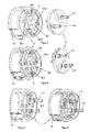
- FIG. 1 is an exploded view of a typical embodiment of a light-emitting profile 11 and a cap according to the invention 1 shown in 0 ° -anssen.
- FIG. 2 the same is shown for a 90 ° arrangement.
- the covering cap 1 is used for the lateral covering of a luminous means.
- both figures show that the illuminant profile 11 has a recess 13. Through the recess 13, the cap 1 can be locked on the lamp profile 11 via a tab 12. This prevents, inter alia, unwanted sliding of the cap 1 from the bulb.
- the covering cap 1 consists of at least one basic element 2 and an adapter 3 separable therefrom. Furthermore, the show FIGS. 3 and 4 in that the adapter piece 3 can be inserted into the base element 2 in at least two positions. These positions are preferably a 0 ° and a 90 ° arrangement.
- FIGS. 5 and 6 show the cap 1 in the assembled state for the 90 ° arrangement ( Fig. 5 ) and the 0 ° arrangement ( Fig. 6 ).
- the base member 2 in a typical embodiment, a sleeve body of two sleeve sections 17.1 and 17.2.
- the two sleeve sections 17.1 and 17.2 are separated by an intermediate floor 20.
- This intermediate bottom 20 serves as a stop for the adapter 3 and has a recess 5 in the form of a Swiss cross.
- the recess 5 in the intermediate bottom 20 four stop tabs 18.1 to 18.4 are formed in a typical embodiment, where the adapter 3 rests in the inserted state. Furthermore, the recess 5 in the form of the Swiss cross in the intermediate bottom 20 of the base member 2 is suitable for at least one, preferably two elevations 7.1 and 7.2 of the adapter 3 to receive. Surveys 7.1 and 7.2 are in FIG. 10 shown in more detail.
- an adapter piece 3 also has locating pins 9.1 to 9.4. These are mounted on a lamp side facing the adapter 3. Furthermore, the fixing pins 9.1 to 9.4 are arranged so that they serve the fixation 'of the adapter piece 3 in recesses 10.1 to 10.4 of the basic element. The recesses 10.1 to 10.4 are arranged in the stop tabs 18.1 to 18.4 of the base element 2. In addition to the additional fixation of the adapter piece 3 in the base element 2, the fixing pins can also be used for the transmission of forces.
- the adapter 3 has recesses 6.1 and 6.2.
- the recesses 6.1 and 6.2 are used for insertion and thus for recording contact pins 4.1 and 4.2.
- the recesses 6.1 and 6.2 end on the side facing the light source side of the adapter 3 in the surveys 7.1 and 7.2, in which they pass into conical receptacles 8.1 and 8.2.
- the contact pins 4.1 and 4.2 are substantially opposite to the surveys 7.1 and 7.2.
- FIG. 11 the adapter 3 is shown with the used contact pins 4.1 and 4.2. Furthermore, in FIG. 11 a distance a is shown. In a typical embodiment, this distance a corresponds to a distance of a G5 or G13 illuminant holder.
- the conical receptacles 8.1 and 8.2 in the surveys 7.1 and 7.2 are provided for receiving a cable with multiple strands, in particular a multi-stranded cable.
- This not-shown multi-seated cable serves a connection between the contact pins 4.1 and 4.2 and an electronics of a light source, which is also not shown in detail.
- the connection between the contact pins 4.1, 4.2 and the multi-strand cable is preferably a crimp connection.
- FIG. 7 It can be seen that an inner ring 14 is located within the sleeve portion 17.1 of the basic element.
- This inner ring 14 has recesses 15.1 and 15.2. These recesses are in the in FIGS. 1 and 2 shown holding rails 16.1 and 16.2 of the lamp profile 11 adapted. By this arrangement, a rotation of the cap can be prevented on the lamp.
- the support rails 16.1 and 16.2 are used in a typical embodiment for receiving the electronics of the lamp and the inclusion of a translucent cover cover, as shown in the DE 10 2011 001 113 A1 is described.
- the adapter By lifting the tab 12, the locking between the cap 1 and the lamp profile 11 is released and the cap 1 can be deducted from the light-emitting profile 11.
- the adapter In order to change the position of the contact pins 4.1 and 4.2, the adapter must be released from the base element and then twisted. Since a flexible cable is used as the connection of the contact pins 4.1 and 4.2 with the electronics of the lamp, the adapter piece 3 can be easily rotated. After rotation through 90 °, the adapter piece 3 can be used again in the base element 2. After insertion of the adapter is on the stop tabs 18.1 to 18.4. Subsequently, the cap 1 is placed back on the lamp profile 11.
- the light source can be used with a rotated by 90 ° emission direction of the light waves generated by the light source in the bulb holder.
Landscapes
- Engineering & Computer Science (AREA)
- General Engineering & Computer Science (AREA)
- Physics & Mathematics (AREA)
- Microelectronics & Electronic Packaging (AREA)
- Optics & Photonics (AREA)
- Non-Portable Lighting Devices Or Systems Thereof (AREA)
- Fastening Of Light Sources Or Lamp Holders (AREA)
- Arrangement Of Elements, Cooling, Sealing, Or The Like Of Lighting Devices (AREA)
Abstract
Description
- Die Erfindung betrifft ein Leuchtmittel mit einer Abdeckkappe nach dem Oberbegriff des Anspruchs 1.
- Bei einem Einsetzmechanismus eines LED-Leuchtmittel, das als Ersatz für ein Leuchtmittel in Form einer Leuchtstoffröhre vorgesehen ist, handelt es sich um denselben Mechanismus, der beim Einsetzen einer Leuchtstoffröhre angewandt wird. Ein solches LED-Leuchtmittel ist zum Beispiel in der
DE 10 2011 001 113 A1 dargestellt. - Das Einsetzen oder Entfernen des Leuchtmittels erfolgt normalerweise durch axiales Drehen in eine beliebige Richtung um 90°. Bei einer gewöhnlichen Leuchtstoffröhre führt dies zu keinen Problemen, da diese in alle Richtungen Licht emittiert.
- Ein LED-Leuchtmittel hingegen emittiert das erzeugte Licht meist nur in eine Richtung. Da aber eine gängige Leuchtstoffröhrenfassung nur in einer bestimmten Position stromführend ist, führt dies immer wieder zu Problemen. So kann es bei der Wandmontage einer Fassung dazu führen, dass das Licht durch das LED-Leuchtmittel anstatt in der gewünschten vertikalen Richtung in horizontaler Richtung abgestrahlt wird.
- Weiterhin kann bei Fassungen von Lampen, die sich in den Decken von Räumen befinden, die stromführende Position der Fassung einbaubedingt um 90° zu der gängigen Position verdreht sein. Dies führt beim Einsatz von den zuvor angeführten LED-Leuchtmitteln dazu, dass das Licht nicht in den Raum in Richtung des Bodens emittiert werden kann, solange die Leuchtmittelfassungen nicht aufwendig umgerüstet werden.
- Aufgabe der Erfindung ist die Nachteile aus dem Stand der Technik zu beseitigen. Insbesondere ist es Aufgabe der Erfindung ein System bereit zu stellen, dass eine Änderung der Position der Kontaktpins an einem Sockel für Leuchtstoffröhren zulässt. Weiterhin ist es Aufgabe der Erfindung, dass eine Änderung der Stellung der Kontaktpins jederzeit, zumindest über die Lebenszeit des Leuchtmittels hinweg, möglich ist. Zudem ist es Aufgabe der Erfindung die Anpassung der Position der Kontaktpins zu ermöglichen, ohne dass dabei die Verbindung zwischen den Kontaktpins und der Elektronik des Leuchtmittels getrennt werden muss
- Zur Lösung der Aufgabe führen die Merkmale nach dem Anspruch 1.
- In einem typischen Ausführungsbeispiel umfasst ein Leuchtmittel ein Leuchtmittelprofil und eine erfindungsgemässe Abdeckkappe. Die Abdeckkappe umfasst zumindest ein Grundelement und ein davon trennbares Anpassstück. Weiterhin umfasst die Abdeckkappe in einer typischen Ausführungsform Kontaktpins, die in das Anpassstück eingesetzt sind. Diese Kontaktpins bilden einen Anschluss, der geeignet ist, in eine Leuchtstoffröhrenfassung, vorzugsweise eine G5 oder G13 Fassung, eingesetzt zu werden.
- Das Grundelement der Abdeckkappe besteht in einer typischen Ausführungsform aus einer Hülse, die durch einen Zwischenboden in zwei Abschnitte getrennt wird. Der Zwischenboden des Grundelements weist in einem typischen Ausführungsbeispiel eine Ausnehmung in Form eines Schweizer Kreuzes auf. Dadurch entstehen im Zwischenboden des Grundelements Anschlagslaschen. In einem typischen Ausführungsbeispiel ist der Zwischenboden somit ein Anschlag für das Anpassstück.
- Das Anpassstück weist auf einer dem Leuchtmittel zugewandten Seite zumindest eine, vorzugsweise zwei Erhebungen auf, die geeignet sind in die Ausnehmung in Form des Schweizer Kreuzes eingeführt zu werden. Die Ausnehmung in Form des Schweizer Kreuzes dient somit als Aufnahme für die Erhebungen des Anpassstücks.
- Weiterhin befinden sich in der Anschlagslaschen des Grundelements weitere Ausnehmungen. Diese dienen der Aufnahme von Fixierstiften, die sich ebenfalls auf der dem Leuchtmittel zugewandten Seite befinden. Diese Fixierstifte sind dazu geeignet die Fixierung des Anpassstücks im Grundelement zu verbessern. Weiterhin sind die Fixierstifte auch dazu geeignet Kräfte vom Grundelement auf das Anpassstück zu übertragen.
- Das Anpassstück ist in zumindest zwei verschiedenen Positionen in das Grundelement einsetzbar. Vorzugsweise handelt es sich um eine 0° und eine 90° Anordnung. Durch die verschiedenen Möglichkeiten das Anpassstück formschlüssig in das Grundelement einzusetzen, kann die Richtung, in die das Licht durch das Leuchtmittel emittiert wird, geändert werden.
- Denkbar sind auch Anordnungen die eine 45° und 135° Anordnung oder eine 30° und 120° Grad Anordnung ermöglichen, um etwa Werbetafeln oder Firmenlogos an Gebäudewänden mit Leuchtmitteln, vorzugsweise energiesparenden LED-Leuchtmitteln, zu beleuchten. Allgemein wird durch die Ausnehmung im Zwischenboden in Form eines Schweizer Kreuzes lediglich eine Änderung der Ausrichtung des Anpassstücks und der darin eingesetzten Kontaktpins um 90° vorgegeben.
- Weiterhin sollen durch die Anmeldung auch andere Formen der Ausnehmung im Grundelement, die eine einfache Änderung der Position der Kontaktpins innerhalb der Abdeckkappe ermöglichen, vorliegend umfasst sein.
- In einem typischen Ausführungsbeispiel werden die Kontaktpins von einer dem Leuchtmittel abgewandten Seite in dafür vorgesehene Ausnehmungen in dem Anpassstück eingesetzt. Die Ausnehmungen, die der Aufnahme und dem Einsetzen der Kontaktpins dienen befinden sich dabei im Wesentlichen auf der gegenüberliegenden Seite der Erhebungen, die in die Ausnehmung in Form des Schweizer Kreuzes des Grundelements eingesetzt werden.
- Um die Kontaktpins mit einer Elektronik des Leuchtmittels verbinden zu können, weisen die Erhebungen auf der dem Leuchtmittel zugewandten Seite des Anpassstücks eine konische Aufnahme auf. Durch Einführen eines Kabels mit mehreren Litzen, insbesondere eines viellitzigen Kabels, in diese Aufnahmen werden die Litzen des Kabels in die Kontaktpins eingeführt. Somit sind die Kontaktpins des Anpassstücks über das viellitzige Kabel mit der Elektronik des Leuchtmittels verbunden.
- Um eine dauerhafte, zumindest nur schwer lösbare Verbindung zwischen dem viellitzigen Kabel und den Kontaktpins zu erhalten, handelt es sich um eine Crimpverbindung.
- Die konische Aufnahme auf der dem Leuchtmittel zugewandten Seite des Anpassstücks bewirkt zudem, dass das viellitzige und dadurch flexible Kabel bei einer Änderung der Position des Anpassstücks nicht zu stark abgeknickt wird. Dies verhindert ein Brechen einzelner Litzen.
- Weiterhin weist das Grundelement der Abdeckkappe in einem typischen Ausführungsbeispiel eine Lasche auf, die ein einfaches Arretieren der Abdeckkappe am Leuchtmittelprofil eines Leuchtmittels ermöglicht. Durch Anheben dieser Lasche kann die Abdeckkappe einfach aus der Arretierung gelöst und anschliessend vom Leuchtmittelprofil des Leuchtmittels gezogen werden. Im Anschluss kann die Position des Anpassstücks und der darin eingebrachten Kontaktpins geändert werden, bevor die Abdeckkappe wieder auf das Leuchtmittelprofil und somit auf das Leuchtmittel aufgesetzt wird.
- Weiterhin umfasst das Grundelement der Abdeckkappe in einem typischen Ausführungsbeispiel einen Innenring, der sich innerhalb des Hülsenabschnitts auf der dem Leuchtmittel zugewandten Seite befindet. Dieser Innenring weist Unterbrechungen auf, die an Halteschienen des Leuchtmittelprofils des Leuchtmittels angepasst sind. Dadurch kann ein Verdrehen der Abdeckkappe auf dem Leuchtmittel verhindert werden. In den Halteschienen des Leuchtmittelprofils sind in einem typischen Ausführungsbeispiel die Elektronik des Leuchtmittels sowie eine Abdeckung eingesetzt und/oder aufgeschoben. Weiterhin sind die Abdeckkappen so konstruiert, dass im Wesentlichen ein Formschluss sowohl zwischen Leuchtmittelprofil und Grundelement der Abdeckkappe als auch zwischen Grundelement und Anpassstück der Abdeckkappe besteht. Dadurch kann gewährleistet werden, dass Belastungen vom Leuchtmittel über die Abdeckkappe an die Fassung des Leuchtmittels übertragen werden können. In typischen Ausführungsformen weisen die Abdeckkappen eine zweifache Sicherheit bezogen auf den durch die Norm vorgeschriebenen Belastungswert auf.
- Weitere Vorteile, Merkmale und Einzelheiten der Erfindung ergeben sich aus der nachfolgenden Beschreibung bevorzugter Ausführungsbeispiele sowie anhand der Zeichnungen; diese zeigen in
- Figur 1
- eine Explosionsdarstellung eines typischen Ausführungsbeispiels eines Leuchtmittelprofils mit einer erfindungsgemässen Abdeckkappe in 0°-Anordnung;
- Figur 2
- eine Explosionsdarstellung des Ausführungsbeispiels nach
Figur 1 in 90°-Anordnung; - Figur 3
- eine Explosionsdarstellung der erfindungsgemässen Abdeckkappe nach
Figur 2 mit einer 90°-Anordnung des Anpassstücks; - Figur 4
- eine Explosionsdarstellung der erfindungsgemässen Abdeckkappe nach
Figur 1 mit einer 0°-Anordnung des Anpassstücks; - Figur 5
- eine perspektivische Ansicht der erfindungsgemässen Abdeckkappe mit eingesetztem Anpassstück in 90°-Anordnung;
- Figur 6
- eine perspektivische Ansicht der erfindungsgemässen Abdeckkappe mit eingesetztem Anpassstück in 0°-Anordnung;
- Figur 7
- eine perspektivische Rückansicht eines erfindungsgemässen Grundelements der Abdeckkappe nach den
Figuren 1 und 2 ; - Figur 8
- eine perspektivische Vorderansicht eines erfindungsgemässen Grundelements der Abdeckkappe nach
Figur 3 ; - Figur 9
- eine perspektivische Ansicht eine dem Leuchtmittel abgewandte Seite eines erfindungsgemässen Anpassstücks;
- Figur 10
- eine perspektivische Ansicht auf die dem Leuchtmittel zugewandte Seite eines erfindungsgemässen Anpassstücks;
- Figur 11
- eine perspektivische Ansicht auf ein erfindungsgemässen Anpassstück mit eingesetzten Kontaktpins.
- In
Figur 1 wird eine Explosionsdarstellung eines typischen Ausführungsbeispiels von einem Leuchtmittelprofil 11 und einer erfindungsgemässen Abdeckkappe 1 in 0°-Anordnung gezeigt. InFigur 2 wird dasselbe für eine 90°-Anordnung gezeigt. In beiden Figuren wird gezeigt, dass die Abdeckkappe 1 zur seitlichen Abdeckung eines Leuchtmittels verwendet wird. - Beide Figuren zeigen, dass das Leuchtmittelprofil 11 eine Ausnehmung 13 aufweist. Durch die Ausnehmung 13 kann über eine Lasche 12 die Abdeckkappe 1 am Leuchtmittelprofil 11 arretiert werden. Dies verhindert unter anderem ein ungewolltes Abgleiten der Abdeckkappe 1 vom Leuchtmittel.
- In
Figur 3 und 4 ist zu sehen, dass die erfindungsgemässe Abdeckkappe 1 zumindest aus einem Grundelement 2 und einem davon trennbaren Anpassstück 3 besteht. Weiterhin zeigen dieFiguren 3 und 4 , dass das Anpassstück 3 in zumindest zwei Positionen in das Grundelement 2 eingesetzt werden kann. Bei diesen Positionen handelt es sich vorzugsweise um eine 0° und eine 90° Anordnung. - Die
Figuren 5 und 6 zeigen die Abdeckkappe 1 in zusammengesetzten Zustand für die 90°-Anordnung (Fig. 5 ) und die 0°-Anordnung (Fig. 6 ). - In der perspektivischen Rückansicht des Grundelements 2 in
Figur 7 und der perspektivischen Vorderansicht des Grundelements 2 inFigur 8 ist dargestellt, dass das Grundelement 2 in einem typischen Ausführungsbeispiel ein Hülsenkörper aus zwei Hülsenabschnitten 17.1 und 17.2 ist. Die beiden Hülsenabschnitte 17.1 und 17.2 werden durch einen Zwischenboden 20 getrennt. Dieser Zwischenboden 20 dient als Anschlag für das Anpassstück 3 und weist eine Ausnehmung 5 in Form eines Schweizer Kreuzes auf. - Durch die Ausnehmung 5 im Zwischenboden 20 werden in einem typischen Ausführungsbeispiel vier Anschlagslaschen 18.1 bis 18. 4 ausgebildet, an denen das Anpassstück 3 im eingesetzten Zustand anliegt. Weiterhin ist die Ausnehmung 5 in Form des Schweizer Kreuzes im Zwischenboden 20 des Grundelements 2 dazu geeignet zumindest eine, vorzugsweise zwei Erhebungen 7.1 und 7.2 des Anpassstücks 3 aufzunehmen. Die Erhebungen 7.1 und 7.2 sind in
Figur 10 näher dargestellt. - In einem typischen Ausführungsbeispiel weist ein Anpassstück 3 zudem Fixierstifte 9.1 bis 9. 4 auf. Diese sind auf einer dem Leuchtmittel zugewandeten Seite des Anpassstücks 3 angebracht. Weiterhin sind die Fixierstifte 9.1 bis 9.4 so angeordnet, dass sie der Fixierung 'des Anpassstücks 3 in Ausnehmungen 10.1 bis 10.4 des Grundelements dienen. Die Ausnehmungen 10.1 bis 10.4 sind in den Anschlaglaschen 18.1 bis 18.4 des Grundelements 2 angeordnet. Neben der zusätzlichen Fixierung des Anpassstücks 3 im Grundelement 2 können die Fixierstifte auch zur Übertragung von Kräften genutzt werden.
- In
Figur 9 ist dargestellt, dass das Anpassstück 3 Ausnehmungen 6.1 und 6.2 aufweist. Auf einer dem Leuchtmittel abgewandten Seite des Anpassstücks 3 dienen die Ausnehmungen 6.1 und 6.2 zum Einführen und damit zur Aufnahme von Kontaktpins 4.1 und 4.2. Die Ausnehmungen 6.1 und 6.2 enden auf der dem Leuchtmittel zugewandten Seite des Anpassstücks 3 in den Erhebungen 7.1 und 7.2, in denen sie in konische Aufnahmen 8.1 und 8.2 übergehen. Somit befinden sich die Kontaktpins 4.1 und 4.2 im Wesentlichen gegenüberliegend zu den Erhebungen 7.1 und 7.2. - In
Figur 11 ist das Anpassstück 3 mit den eingesetzten Kontaktpins 4.1 und 4.2 dargestellt. Weiterhin ist inFigur 11 ein Abstand a dargestellt. Dieser Abstand a entspricht in einem typischen Ausführungsbeispiel einem Abstand einer G5 oder G13 Leuchtmittelfassung. - Die konischen Aufnahmen 8.1 und 8.2 in den Erhebungen 7.1 und 7.2 sind zur Aufnahme eines Kabels mit mehreren Litzen, insbesondere eines viellitzigen Kabels, vorgesehen. Dieses nicht näher dargestellte viellitzige Kabel dient einer Verbindung zwischen den Kontaktpins 4.1 und 4.2 und einer Elektronik eines Leuchtmittels, welche ebenfalls nicht näher dargestellt ist.
- Durch das Einführen des viellitzigen Kabels in die Ausnehmungen 6.1 und 6.2 sind diese mit den Kontaktpins 4.1, 4.2 verbunden. Um diese Verbindung formstabil und dauerhaft zu gestalten, handelt es sich bei der Verbindung zwischen den Kontaktpins 4.1, 4.2 und dem viellitzigen Kabel vorzugsweise um eine Crimpverbindung.
- In
Figur 7 ist zu sehen dass sich innerhalb des Hülsenabschnitts 17.1 des Grundelements ein Innenring 14 befindet. Dieser Innenring 14 weist Ausnehmungen 15.1 und 15.2 auf. Diese Ausnehmungen sind an die inFigur 1 und 2 dargestellten Halteschienen 16.1 und 16.2 des Leuchtmittelprofils 11 angepasst. Durch diese Anordnung kann ein Verdrehen der Abdeckkappe auf dem Leuchtmittel verhindert werden. Die Halteschienen 16.1 und 16.2 dienen in einem typischen Ausführungsbeispiel zur Aufnahme der Elektronik des Leuchtmittels sowie der Aufnahme einer lichtdurchlässigen Abdeckung Abdeckung, wie dies in derDE 10 2011 001 113 A1 beschrieben ist. - Die Schritte zur Änderung der Position des Anpassstücks und somit der Kontaktpins 4.1, 4.2 von einer 0°- auf eine 90°-Anordnung, oder umgekehrt, sind die folgenden:
- Durch Anheben der Lasche 12 wird die Arretierung zwischen der Abdeckkappe 1 und dem Leuchtmittelprofil 11 gelöst und die Abdeckkappe 1 kann vom Leuchtmittelprofil 11 abgezogen werden. Um die Position der Kontaktpins 4.1 und 4.2 zu ändern, muss das Anpassstück aus dem Grundelement gelöst und anschliessend verdreht werden. Da als Verbindung von den Kontaktpins 4.1 und 4.2 mit der Elektronik des Leuchtmittels ein flexibles Kabel genutzt wird, kann das Anpassstück 3 problemlos verdreht werden. Nach der Drehung um 90° kann das Anpassstück 3 wieder in das Grundelement 2 eingesetzt werden. Nach dem Einsetzen liegt das Anpassstück auf den Anschlagslaschen 18.1 bis 18.4 auf. Anschliessend wird die Abdeckkappe 1 wieder auf das Leuchtmittelprofil 11 aufgesetzt. Nach dem Ändern der Position des Anpassstücks der Abdeckkappe auf der einen Seite des Leuchtmittels muss der Vorgang auf der anderen Seite des Leuchtmittels und der dortigen Abdeckkappe 1 wiederholt werden. Danach kann das Leuchtmittel mit einer um 90° gedrehten Emissionsrichtung der durch das Leuchtmittel erzeugten Lichtwellen in die Leuchtmittelfassung eingesetzt werden.
-
1 Abdeckkappe 34 a Abstand 2 Grundelement 35 3 Anpassstück 36 4 Kontaktpin 37 5 Ausnehmung 38 6 Ausnehmung für Kontaktpin 39 7 Erhebung 40 8 Konische Aufnahme 41 9 Fixierstift 42 10 Ausnehmung 43 11 Leuchtmittelprofil 44 12 Lasche 45 13 Ausnehmung 46 14 Innenring 47 15 Ausnehmung 48 16 Halteschienen 49 17 Hülse 50 18 Anschlaglaschen 51 19 52 20 Zwischenboden 53 21 54 22 55 23 56 24 57 25 58 26 59 27 60 28 61 29 62 30 63 31 64 32 65 33 66
Claims (13)
- Leuchtmittel mit einem Leuchtmittelprofil (11) und zumindest einer seitlichen Abdeckkappe (1),
dadurch gekennzeichnet, dass
die Abdeckkappe (1) zumindest aus einem Grundelement (2) und einem davon trennbaren Anpassstück (3) besteht. - Leuchtmittel nach Anspruch 1, dadurch gekennzeichnet, dass das Grundelement (2) einen Zwischenboden (20) aufweist, der ein Anschlag für das Anpassstück (3) ist.
- Leuchtmittel nach einem der Ansprüche 1 bis 2, dadurch gekennzeichnet, dass der Zwischenboden (20) eine Ausnehmung (5), insbesondere in Form eines Schweizer Kreuzes, aufweist, wodurch Anschlagslaschen (18.1-18.4) ausgebildet werden.
- Leuchtmittel nach einem der Ansprüche 1 bis 3, dadurch gekennzeichnet, dass die Ausnehmung (5) zur Aufnahme von zumindest einer Erhebung (7.1, 7.2) des Anpassstücks (3) geeignet ist.
- Leuchtmittel nach einem der Ansprüche 1 bis 4, dadurch gekennzeichnet, dass Anpassstück (3) in zumindest zwei Positionen, vorzugsweise 0° und 90°, in das Grundelement (2) einsetzbar ist.
- Leuchtmittel nach einem der Ansprüche 1 bis 5, dadurch gekennzeichnet, dass das Anpassstück (3) Fixierstifte (9.1-9.4) zur Fixierung in Ausnehmungen (10.1-10.4) in den Anschlaglaschen (18.1-18.4) des Grundelements (2) aufweist.
- Leuchtmittel nach einem der Ansprüche 1 bis 6, dadurch gekennzeichnet, dass in das Anpassstück (3) auf einer dem Leuchtmittel abgewandten Seite, im Wesentlichen den Erhebungen (7.1, 7.2) gegenüberliegend, Kontaktpins (4.1, 4.2) in Ausnehmungen (6.1, 6.2) einsetzbar sind.
- Leuchtmittel nach einem der Ansprüche 1 bis 7, dadurch gekennzeichnet, dass die Erhebung (7.1, 7.2) eine konische Aufnahme (8.1, 8.2) für ein Kabel mit mehreren Litzen auf einer dem Leuchtmittel zugewandten Seite aufweist.
- Leuchtmittel nach einem der Ansprüche 1 bis 8, dadurch gekennzeichnet, dass die Kontaktpins (4.1, 4.2) der Abdeckkappe (1) über das Kabel mit mehreren Litzen mit dem Leuchtmittel verbunden sind.
- Leuchtmittel nach einem der Ansprüche 1 bis 9, dadurch gekennzeichnet, dass die Verbindung zwischen dem Kabel mit mehreren Litzen und dem Kontaktpin (4.1, 4.2) eine Crimpverbindung ist.
- Leuchtmittel nach einem der Ansprüche 1 bis 10, dadurch gekennzeichnet, dass das Grundelement (2) einen Innenring (14) mit Ausnehmungen (15.1, 15.2) aufweist, welche an Halteschienen (16.1, 16.2) eines Leuchtmittelprofils (11) angepasst sind.
- Leuchtmittel nach einem der Ansprüche 1 bis 11, dadurch gekennzeichnet, dass das Grundelement (2) eine Lasche (12) zur Arretierung der Abdeckkappe (1) an dem Leuchtmittelprofil (11) aufweist.
- Abdeckkappe (1) nach einem der Ansprüche 1 bis 12 zur Verwendung zur seitlichen Abdeckung eines Leuchtmittels.
Priority Applications (1)
| Application Number | Priority Date | Filing Date | Title |
|---|---|---|---|
| PL14165794T PL2838319T3 (pl) | 2013-04-26 | 2014-04-24 | Element świetlny z pokrywą |
Applications Claiming Priority (1)
| Application Number | Priority Date | Filing Date | Title |
|---|---|---|---|
| DE201310104291 DE102013104291A1 (de) | 2013-04-26 | 2013-04-26 | Leuchtmittel mit einer Abdeckkappe |
Publications (3)
| Publication Number | Publication Date |
|---|---|
| EP2838319A2 true EP2838319A2 (de) | 2015-02-18 |
| EP2838319A3 EP2838319A3 (de) | 2015-08-19 |
| EP2838319B1 EP2838319B1 (de) | 2020-10-21 |
Family
ID=50624440
Family Applications (1)
| Application Number | Title | Priority Date | Filing Date |
|---|---|---|---|
| EP14165794.0A Active EP2838319B1 (de) | 2013-04-26 | 2014-04-24 | Leuchtmittel mit einer Abdeckkappe |
Country Status (6)
| Country | Link |
|---|---|
| EP (1) | EP2838319B1 (de) |
| DE (1) | DE102013104291A1 (de) |
| DK (1) | DK2838319T3 (de) |
| ES (1) | ES2843203T3 (de) |
| HU (1) | HUE053274T2 (de) |
| PL (1) | PL2838319T3 (de) |
Citations (1)
| Publication number | Priority date | Publication date | Assignee | Title |
|---|---|---|---|---|
| DE102011001113A1 (de) | 2011-02-09 | 2012-08-09 | German LED Tech GmbH | LED-Leuchte |
Family Cites Families (5)
| Publication number | Priority date | Publication date | Assignee | Title |
|---|---|---|---|---|
| DE102009054994B4 (de) * | 2009-12-18 | 2012-06-28 | Osram Ag | Endstück für Retrofit-Leuchtstofflampe und Retrofit-Leuchtstofflampe |
| ES2545134T3 (es) * | 2010-05-07 | 2015-09-08 | Fraunhofer-Gesellschaft zur Förderung der angewandten Forschung e.V. | Medio de iluminación para reemplazar un tubo fluorescente |
| DE202011003701U1 (de) * | 2011-03-09 | 2011-06-01 | Samtleben Invest GmbH, 82178 | Adapter und Adaptersystem für Leuchtstoffröhrenfassungen |
| DE202011110097U1 (de) * | 2011-12-06 | 2013-03-18 | Diehl Aerospace Gmbh | LED-Leuchtmittel |
| DE202012009313U1 (de) * | 2012-09-27 | 2012-11-12 | Jörg Richter | Schaltschrankleuchte |
-
2013
- 2013-04-26 DE DE201310104291 patent/DE102013104291A1/de not_active Withdrawn
-
2014
- 2014-04-24 DK DK14165794.0T patent/DK2838319T3/da active
- 2014-04-24 PL PL14165794T patent/PL2838319T3/pl unknown
- 2014-04-24 EP EP14165794.0A patent/EP2838319B1/de active Active
- 2014-04-24 ES ES14165794T patent/ES2843203T3/es active Active
- 2014-04-24 HU HUE14165794A patent/HUE053274T2/hu unknown
Patent Citations (1)
| Publication number | Priority date | Publication date | Assignee | Title |
|---|---|---|---|---|
| DE102011001113A1 (de) | 2011-02-09 | 2012-08-09 | German LED Tech GmbH | LED-Leuchte |
Also Published As
| Publication number | Publication date |
|---|---|
| HUE053274T2 (hu) | 2021-06-28 |
| PL2838319T3 (pl) | 2021-07-19 |
| DE102013104291A1 (de) | 2014-10-30 |
| EP2838319A3 (de) | 2015-08-19 |
| EP2838319B1 (de) | 2020-10-21 |
| DK2838319T3 (da) | 2021-01-18 |
| ES2843203T3 (es) | 2021-07-16 |
Similar Documents
| Publication | Publication Date | Title |
|---|---|---|
| EP0798951A2 (de) | Konvertergehäuse | |
| EP3114400B1 (de) | Leuchte bzw. beleuchtungsanordnung mit länglichem trägerelement und lösbar befestigbarem leuchtmodul | |
| DE29909282U1 (de) | Leuchte | |
| DE19801954B4 (de) | Leuchtensystem | |
| EP3165821B1 (de) | Längliches lichtbandelement | |
| DE202014004861U1 (de) | Lampe und Adapter für eine Lampe | |
| EP2838319A2 (de) | Leuchtmittel mit einer Abdeckkappe | |
| DE102018101503B4 (de) | Elektrische Steckverbindung zum Verbinden eines Leuchtmittels mit einer elektrischen Anschlussleitung | |
| DE202018106703U1 (de) | Wand- oder Deckenleuchte | |
| DE102012221454A1 (de) | Leuchte mit einem Leuchtengehäuse, das ein Profilelement umfasst | |
| DE202012103061U1 (de) | Leuchtmodul und Leuchtsystem mit Leuchtmodul | |
| DE202023103963U1 (de) | Leuchte | |
| DE202007011212U1 (de) | Leuchte mit Raster zur Lichtabgabe | |
| DE102011016763B3 (de) | Beleuchtungseinrichtung, Leuchtkörperhalter und Leuchtkörper dafür | |
| EP2453170B1 (de) | Befestigungsvorrichtung für Sensoren an Leuchten | |
| DE202023102585U1 (de) | Lampe mit verbessertem Anschluss | |
| DE19858605C2 (de) | Langfeldleuchte | |
| DE202007007437U1 (de) | Leuchtkörpersystem sowie Leuchtkörper für ein Leuchtkörpersystem | |
| DE2037285A1 (de) | Einrichtung zur losbaren Befestigung einer Leuchte an der Decke oder der Wand eines Raumes | |
| EP1132681B1 (de) | Tragschienensystem | |
| DE202025107506U1 (de) | Lampe zur Integration in ein Schrankgerüst | |
| DE29906741U1 (de) | Leuchte | |
| DE102011001410A1 (de) | Adapter für eine Leuchtmittelfassung | |
| DE202020107403U1 (de) | Stehleuchte | |
| DE202015002255U1 (de) | Beleuchtungsanordnung und Sportgerätehalterung mit einer solchen Beleuchtungsanordnung |
Legal Events
| Date | Code | Title | Description |
|---|---|---|---|
| 17P | Request for examination filed |
Effective date: 20140424 |
|
| AK | Designated contracting states |
Kind code of ref document: A2 Designated state(s): AL AT BE BG CH CY CZ DE DK EE ES FI FR GB GR HR HU IE IS IT LI LT LU LV MC MK MT NL NO PL PT RO RS SE SI SK SM TR |
|
| AX | Request for extension of the european patent |
Extension state: BA ME |
|
| PUAI | Public reference made under article 153(3) epc to a published international application that has entered the european phase |
Free format text: ORIGINAL CODE: 0009012 |
|
| PUAL | Search report despatched |
Free format text: ORIGINAL CODE: 0009013 |
|
| AK | Designated contracting states |
Kind code of ref document: A3 Designated state(s): AL AT BE BG CH CY CZ DE DK EE ES FI FR GB GR HR HU IE IS IT LI LT LU LV MC MK MT NL NO PL PT RO RS SE SI SK SM TR |
|
| AX | Request for extension of the european patent |
Extension state: BA ME |
|
| RIC1 | Information provided on ipc code assigned before grant |
Ipc: F21K 99/00 20100101ALI20150710BHEP Ipc: F21V 15/01 20060101ALI20150710BHEP Ipc: H01R 33/00 20060101ALI20150710BHEP Ipc: F21V 15/015 20060101ALI20150710BHEP Ipc: H05B 33/08 20060101AFI20150710BHEP Ipc: F21V 23/06 20060101ALI20150710BHEP |
|
| R17P | Request for examination filed (corrected) |
Effective date: 20160216 |
|
| RBV | Designated contracting states (corrected) |
Designated state(s): AL AT BE BG CH CY CZ DE DK EE ES FI FR GB GR HR HU IE IS IT LI LT LU LV MC MK MT NL NO PL PT RO RS SE SI SK SM TR |
|
| STAA | Information on the status of an ep patent application or granted ep patent |
Free format text: STATUS: EXAMINATION IS IN PROGRESS |
|
| 17Q | First examination report despatched |
Effective date: 20171016 |
|
| GRAP | Despatch of communication of intention to grant a patent |
Free format text: ORIGINAL CODE: EPIDOSNIGR1 |
|
| STAA | Information on the status of an ep patent application or granted ep patent |
Free format text: STATUS: GRANT OF PATENT IS INTENDED |
|
| INTG | Intention to grant announced |
Effective date: 20200608 |
|
| GRAS | Grant fee paid |
Free format text: ORIGINAL CODE: EPIDOSNIGR3 |
|
| GRAA | (expected) grant |
Free format text: ORIGINAL CODE: 0009210 |
|
| STAA | Information on the status of an ep patent application or granted ep patent |
Free format text: STATUS: THE PATENT HAS BEEN GRANTED |
|
| AK | Designated contracting states |
Kind code of ref document: B1 Designated state(s): AL AT BE BG CH CY CZ DE DK EE ES FI FR GB GR HR HU IE IS IT LI LT LU LV MC MK MT NL NO PL PT RO RS SE SI SK SM TR |
|
| REG | Reference to a national code |
Ref country code: GB Ref legal event code: FG4D Free format text: NOT ENGLISH |
|
| REG | Reference to a national code |
Ref country code: CH Ref legal event code: EP |
|
| REG | Reference to a national code |
Ref country code: IE Ref legal event code: FG4D Free format text: LANGUAGE OF EP DOCUMENT: GERMAN |
|
| REG | Reference to a national code |
Ref country code: DE Ref legal event code: R096 Ref document number: 502014014907 Country of ref document: DE |
|
| REG | Reference to a national code |
Ref country code: AT Ref legal event code: REF Ref document number: 1327208 Country of ref document: AT Kind code of ref document: T Effective date: 20201115 |
|
| RAP2 | Party data changed (patent owner data changed or rights of a patent transferred) |
Owner name: GERMAN LED TECH GMBH |
|
| REG | Reference to a national code |
Ref country code: DK Ref legal event code: T3 Effective date: 20210111 Ref country code: FI Ref legal event code: FGE |
|
| REG | Reference to a national code |
Ref country code: SE Ref legal event code: TRGR |
|
| REG | Reference to a national code |
Ref country code: CH Ref legal event code: NV Representative=s name: ARIE WUBBEN C/O MEDIPACK AG, CH |
|
| REG | Reference to a national code |
Ref country code: NO Ref legal event code: T2 Effective date: 20201021 |
|
| REG | Reference to a national code |
Ref country code: NL Ref legal event code: MP Effective date: 20201021 |
|
| PG25 | Lapsed in a contracting state [announced via postgrant information from national office to epo] |
Ref country code: RS Free format text: LAPSE BECAUSE OF FAILURE TO SUBMIT A TRANSLATION OF THE DESCRIPTION OR TO PAY THE FEE WITHIN THE PRESCRIBED TIME-LIMIT Effective date: 20201021 Ref country code: PT Free format text: LAPSE BECAUSE OF FAILURE TO SUBMIT A TRANSLATION OF THE DESCRIPTION OR TO PAY THE FEE WITHIN THE PRESCRIBED TIME-LIMIT Effective date: 20210222 Ref country code: NL Free format text: LAPSE BECAUSE OF FAILURE TO SUBMIT A TRANSLATION OF THE DESCRIPTION OR TO PAY THE FEE WITHIN THE PRESCRIBED TIME-LIMIT Effective date: 20201021 Ref country code: GR Free format text: LAPSE BECAUSE OF FAILURE TO SUBMIT A TRANSLATION OF THE DESCRIPTION OR TO PAY THE FEE WITHIN THE PRESCRIBED TIME-LIMIT Effective date: 20210122 |
|
| REG | Reference to a national code |
Ref country code: LT Ref legal event code: MG4D |
|
| PG25 | Lapsed in a contracting state [announced via postgrant information from national office to epo] |
Ref country code: IS Free format text: LAPSE BECAUSE OF FAILURE TO SUBMIT A TRANSLATION OF THE DESCRIPTION OR TO PAY THE FEE WITHIN THE PRESCRIBED TIME-LIMIT Effective date: 20210221 Ref country code: LV Free format text: LAPSE BECAUSE OF FAILURE TO SUBMIT A TRANSLATION OF THE DESCRIPTION OR TO PAY THE FEE WITHIN THE PRESCRIBED TIME-LIMIT Effective date: 20201021 Ref country code: BG Free format text: LAPSE BECAUSE OF FAILURE TO SUBMIT A TRANSLATION OF THE DESCRIPTION OR TO PAY THE FEE WITHIN THE PRESCRIBED TIME-LIMIT Effective date: 20210121 |
|
| REG | Reference to a national code |
Ref country code: HU Ref legal event code: AG4A Ref document number: E053274 Country of ref document: HU |
|
| PG25 | Lapsed in a contracting state [announced via postgrant information from national office to epo] |
Ref country code: HR Free format text: LAPSE BECAUSE OF FAILURE TO SUBMIT A TRANSLATION OF THE DESCRIPTION OR TO PAY THE FEE WITHIN THE PRESCRIBED TIME-LIMIT Effective date: 20201021 |
|
| REG | Reference to a national code |
Ref country code: ES Ref legal event code: FG2A Ref document number: 2843203 Country of ref document: ES Kind code of ref document: T3 Effective date: 20210716 |
|
| REG | Reference to a national code |
Ref country code: DE Ref legal event code: R097 Ref document number: 502014014907 Country of ref document: DE |
|
| PG25 | Lapsed in a contracting state [announced via postgrant information from national office to epo] |
Ref country code: RO Free format text: LAPSE BECAUSE OF FAILURE TO SUBMIT A TRANSLATION OF THE DESCRIPTION OR TO PAY THE FEE WITHIN THE PRESCRIBED TIME-LIMIT Effective date: 20201021 Ref country code: SK Free format text: LAPSE BECAUSE OF FAILURE TO SUBMIT A TRANSLATION OF THE DESCRIPTION OR TO PAY THE FEE WITHIN THE PRESCRIBED TIME-LIMIT Effective date: 20201021 Ref country code: LT Free format text: LAPSE BECAUSE OF FAILURE TO SUBMIT A TRANSLATION OF THE DESCRIPTION OR TO PAY THE FEE WITHIN THE PRESCRIBED TIME-LIMIT Effective date: 20201021 Ref country code: EE Free format text: LAPSE BECAUSE OF FAILURE TO SUBMIT A TRANSLATION OF THE DESCRIPTION OR TO PAY THE FEE WITHIN THE PRESCRIBED TIME-LIMIT Effective date: 20201021 Ref country code: SM Free format text: LAPSE BECAUSE OF FAILURE TO SUBMIT A TRANSLATION OF THE DESCRIPTION OR TO PAY THE FEE WITHIN THE PRESCRIBED TIME-LIMIT Effective date: 20201021 |
|
| PLBE | No opposition filed within time limit |
Free format text: ORIGINAL CODE: 0009261 |
|
| STAA | Information on the status of an ep patent application or granted ep patent |
Free format text: STATUS: NO OPPOSITION FILED WITHIN TIME LIMIT |
|
| 26N | No opposition filed |
Effective date: 20210722 |
|
| PG25 | Lapsed in a contracting state [announced via postgrant information from national office to epo] |
Ref country code: AL Free format text: LAPSE BECAUSE OF FAILURE TO SUBMIT A TRANSLATION OF THE DESCRIPTION OR TO PAY THE FEE WITHIN THE PRESCRIBED TIME-LIMIT Effective date: 20201021 |
|
| REG | Reference to a national code |
Ref country code: DE Ref legal event code: R079 Ref document number: 502014014907 Country of ref document: DE Free format text: PREVIOUS MAIN CLASS: H05B0033080000 Ipc: H05B0044000000 |
|
| PG25 | Lapsed in a contracting state [announced via postgrant information from national office to epo] |
Ref country code: SI Free format text: LAPSE BECAUSE OF FAILURE TO SUBMIT A TRANSLATION OF THE DESCRIPTION OR TO PAY THE FEE WITHIN THE PRESCRIBED TIME-LIMIT Effective date: 20201021 Ref country code: MC Free format text: LAPSE BECAUSE OF FAILURE TO SUBMIT A TRANSLATION OF THE DESCRIPTION OR TO PAY THE FEE WITHIN THE PRESCRIBED TIME-LIMIT Effective date: 20201021 |
|
| REG | Reference to a national code |
Ref country code: NL Ref legal event code: NE Effective date: 20220208 |
|
| PG25 | Lapsed in a contracting state [announced via postgrant information from national office to epo] |
Ref country code: IE Free format text: LAPSE BECAUSE OF NON-PAYMENT OF DUE FEES Effective date: 20210424 |
|
| PG25 | Lapsed in a contracting state [announced via postgrant information from national office to epo] |
Ref country code: IS Free format text: LAPSE BECAUSE OF FAILURE TO SUBMIT A TRANSLATION OF THE DESCRIPTION OR TO PAY THE FEE WITHIN THE PRESCRIBED TIME-LIMIT Effective date: 20210221 |
|
| REG | Reference to a national code |
Ref country code: NL Ref legal event code: NG |
|
| REG | Reference to a national code |
Ref country code: NL Ref legal event code: FP |
|
| PG25 | Lapsed in a contracting state [announced via postgrant information from national office to epo] |
Ref country code: NL Free format text: LAPSE BECAUSE OF FAILURE TO SUBMIT A TRANSLATION OF THE DESCRIPTION OR TO PAY THE FEE WITHIN THE PRESCRIBED TIME-LIMIT Effective date: 20201021 |
|
| PGRI | Patent reinstated in contracting state [announced from national office to epo] |
Ref country code: NL Effective date: 20230215 |
|
| PG25 | Lapsed in a contracting state [announced via postgrant information from national office to epo] |
Ref country code: CY Free format text: LAPSE BECAUSE OF FAILURE TO SUBMIT A TRANSLATION OF THE DESCRIPTION OR TO PAY THE FEE WITHIN THE PRESCRIBED TIME-LIMIT Effective date: 20201021 |
|
| P01 | Opt-out of the competence of the unified patent court (upc) registered |
Effective date: 20230529 |
|
| PG25 | Lapsed in a contracting state [announced via postgrant information from national office to epo] |
Ref country code: MK Free format text: LAPSE BECAUSE OF FAILURE TO SUBMIT A TRANSLATION OF THE DESCRIPTION OR TO PAY THE FEE WITHIN THE PRESCRIBED TIME-LIMIT Effective date: 20201021 |
|
| PG25 | Lapsed in a contracting state [announced via postgrant information from national office to epo] |
Ref country code: TR Free format text: LAPSE BECAUSE OF FAILURE TO SUBMIT A TRANSLATION OF THE DESCRIPTION OR TO PAY THE FEE WITHIN THE PRESCRIBED TIME-LIMIT Effective date: 20201021 |
|
| PG25 | Lapsed in a contracting state [announced via postgrant information from national office to epo] |
Ref country code: MT Free format text: LAPSE BECAUSE OF FAILURE TO SUBMIT A TRANSLATION OF THE DESCRIPTION OR TO PAY THE FEE WITHIN THE PRESCRIBED TIME-LIMIT Effective date: 20201021 |
|
| PGFP | Annual fee paid to national office [announced via postgrant information from national office to epo] |
Ref country code: NL Payment date: 20250423 Year of fee payment: 12 |
|
| PGFP | Annual fee paid to national office [announced via postgrant information from national office to epo] |
Ref country code: LU Payment date: 20250417 Year of fee payment: 12 |
|
| PGFP | Annual fee paid to national office [announced via postgrant information from national office to epo] |
Ref country code: FI Payment date: 20250417 Year of fee payment: 12 |
|
| PGFP | Annual fee paid to national office [announced via postgrant information from national office to epo] |
Ref country code: PL Payment date: 20250414 Year of fee payment: 12 Ref country code: DE Payment date: 20250625 Year of fee payment: 12 |
|
| PGFP | Annual fee paid to national office [announced via postgrant information from national office to epo] |
Ref country code: GB Payment date: 20250417 Year of fee payment: 12 Ref country code: DK Payment date: 20250417 Year of fee payment: 12 Ref country code: ES Payment date: 20250519 Year of fee payment: 12 |
|
| PGFP | Annual fee paid to national office [announced via postgrant information from national office to epo] |
Ref country code: HU Payment date: 20250425 Year of fee payment: 12 Ref country code: NO Payment date: 20250424 Year of fee payment: 12 |
|
| PGFP | Annual fee paid to national office [announced via postgrant information from national office to epo] |
Ref country code: BE Payment date: 20250417 Year of fee payment: 12 Ref country code: IT Payment date: 20250422 Year of fee payment: 12 |
|
| PGFP | Annual fee paid to national office [announced via postgrant information from national office to epo] |
Ref country code: FR Payment date: 20250425 Year of fee payment: 12 |
|
| PGFP | Annual fee paid to national office [announced via postgrant information from national office to epo] |
Ref country code: CH Payment date: 20250501 Year of fee payment: 12 |
|
| PGFP | Annual fee paid to national office [announced via postgrant information from national office to epo] |
Ref country code: AT Payment date: 20250423 Year of fee payment: 12 |
|
| PGFP | Annual fee paid to national office [announced via postgrant information from national office to epo] |
Ref country code: CZ Payment date: 20250411 Year of fee payment: 12 |
|
| PGFP | Annual fee paid to national office [announced via postgrant information from national office to epo] |
Ref country code: SE Payment date: 20250417 Year of fee payment: 12 |