EP2838269A1 - Video coding using artificial reference frames - Google Patents
Video coding using artificial reference frames Download PDFInfo
- Publication number
- EP2838269A1 EP2838269A1 EP20140185705 EP14185705A EP2838269A1 EP 2838269 A1 EP2838269 A1 EP 2838269A1 EP 20140185705 EP20140185705 EP 20140185705 EP 14185705 A EP14185705 A EP 14185705A EP 2838269 A1 EP2838269 A1 EP 2838269A1
- Authority
- EP
- European Patent Office
- Prior art keywords
- reference image
- signal
- prediction signal
- section
- producing
- Prior art date
- Legal status (The legal status is an assumption and is not a legal conclusion. Google has not performed a legal analysis and makes no representation as to the accuracy of the status listed.)
- Ceased
Links
Images


Classifications
-
- H—ELECTRICITY
- H04—ELECTRIC COMMUNICATION TECHNIQUE
- H04N—PICTORIAL COMMUNICATION, e.g. TELEVISION
- H04N19/00—Methods or arrangements for coding, decoding, compressing or decompressing digital video signals
- H04N19/50—Methods or arrangements for coding, decoding, compressing or decompressing digital video signals using predictive coding
- H04N19/503—Methods or arrangements for coding, decoding, compressing or decompressing digital video signals using predictive coding involving temporal prediction
- H04N19/51—Motion estimation or motion compensation
- H04N19/573—Motion compensation with multiple frame prediction using two or more reference frames in a given prediction direction
-
- H—ELECTRICITY
- H04—ELECTRIC COMMUNICATION TECHNIQUE
- H04N—PICTORIAL COMMUNICATION, e.g. TELEVISION
- H04N19/00—Methods or arrangements for coding, decoding, compressing or decompressing digital video signals
- H04N19/50—Methods or arrangements for coding, decoding, compressing or decompressing digital video signals using predictive coding
- H04N19/503—Methods or arrangements for coding, decoding, compressing or decompressing digital video signals using predictive coding involving temporal prediction
- H04N19/51—Motion estimation or motion compensation
-
- H—ELECTRICITY
- H04—ELECTRIC COMMUNICATION TECHNIQUE
- H04N—PICTORIAL COMMUNICATION, e.g. TELEVISION
- H04N19/00—Methods or arrangements for coding, decoding, compressing or decompressing digital video signals
- H04N19/50—Methods or arrangements for coding, decoding, compressing or decompressing digital video signals using predictive coding
- H04N19/593—Methods or arrangements for coding, decoding, compressing or decompressing digital video signals using predictive coding involving spatial prediction techniques
Definitions
- the present invention relates to a moving picture encoding device, a moving picture decoding device, a moving picture encoding method, a moving picture decoding method, a moving picture encoding program, and a moving picture decoding program. Particularly, the invention relates to producing a prediction signal in prediction encoding and prediction decoding.
- a compression encoding technology is used to efficiently transmit and store moving picture data.
- moving picture technology MPEG-1, 2, 4, and H.261 to H.264 standards are widely used.
- a prediction signal of a target image serving as an encoding target is produced by using adjacent images side by side on a temporal axis and then a difference between the target image and the prediction signal is encoded, thereby realizing a data amount reduction.
- This technique is called inter-frame encoding.
- one frame image is divided into block regions each composed of 16 ⁇ 16 pixels, and the image is encoded on the block-by-block basis.
- a prediction signal is produced by carrying out motion compensating prediction on a target block of an encoding target image with reference to other frames that have been encoded and restored. Then, a differential value of the target block and the prediction signal is obtained. The differential value is discrete-cosine-transformed and quantized so as to produce encoded data.
- a bidirectional prediction method is used to reduce quantized noises included in prediction signals and predict a newly appearing image signal.
- two pieces of motion amount are set to a target block.
- First motion amount determines a first prediction signal from a first reference image that is a temporally past image relative to the target block
- second motion amount determines a second prediction signal from a second reference image that is a temporally future image relative to the target block.
- the first and second prediction signals are averaged to produce a prediction signal.
- the first and second prediction signals may be obtained from two respective reference images that are temporally past images, and averaged to produce a prediction signal.
- Patent Literature 1 United States Patent No. 6259739 .
- Non Patent Literature 1 Iain E. G. Richardson, "H.264 and MPEG-4 Video Compression", John Wiley & Sons, 2003, pp.170-176, 207-212 .
- Moving pictures may include some images in which textures (pictures) change over time.
- textures pictures
- Such texture is called a "dynamic texture”.
- the related art described above is based on the assumption that pixels in a target block serving as an encoding target are rarely different from those in the front and back frames relative to the target block. Accordingly, if the assumption is true that a motion compensated prediction signal is similar to a target signal, the differential signal can be made small. In other words, data compression is achieved by utilizing a characteristic that signals between frames have high correlation.
- the differential signal becomes large because a pixel of the target block is not similar to the pixel in the prediction signal at the same location as that of the target block due to changes in the pixel value over time even though prediction is carried out from the front and back frames. Consequently, the amount of compressed data may increase. Specifically, moving pictures including dynamic textures show low correlation between frames. The related art, thus, hardly realizes a high compression rate. Particularly, when encoding is carried out at a low bit rate, a differential signal having a large data amount is hardly transmitted. A problem, thus, arises in that texture signals in reproduction images are almost lost.
- the present invention aims to provide a moving picture encoding device, a moving picture decoding device, a moving picture encoding method, a moving picture decoding method, a moving picture encoding program, and a moving picture decoding program that can reduce the data amount of compressed moving pictures by producing prediction signals suitable for moving pictures that include dynamic textures.
- a moving picture encoding device of the present invention includes: an input section receiving a target signal included in an encoding target image of a moving picture composed of a plurality of images; a prediction signal generation section producing a prediction signal with respect to the target signal; a difference generation section producing a differential signal indicating a difference between the target signal and the prediction signal; an encoding section encoding the differential signal by a certain method so as to produce an encoded differential signal; a decoding section decoding the encoded differential signal so as to produce a decoded differential signal; an adding section adding the prediction signal to the decoded differential signal so as to produce a reproduction signal; a storage section storing the reproduction signal as a reference image referred to in producing the prediction signal; and a reference image generation section obtaining an observation matrix by using a pre-existing reference image that is the reference image having been already produced and stored in the storage section, producing, based on the observation matrix, a new reference image newly serving as the reference image, and storing the new
- a moving picture encoding method of the present invention includes: receiving a target signal included in an encoding target image of a moving picture composed of a plurality of images by an input section; producing a prediction signal with respect to the target signal by a prediction signal generation section; producing a differential signal indicating a difference between the target signal and the prediction signal by a difference generation section; encoding the differential signal by a certain method so as to produce an encoded differential signal by an encoding section; decoding the encoded differential signal so as to produce a decoded differential signal by a decoding section; adding the prediction signal to the decoded differential signal so as to produce a reproduction signal by an adding section; storing the reproduction signal by a storage section as a reference image referred to in producing the prediction signal; and obtaining an observation matrix by using a pre-existing reference image that is the reference image having been already produced and stored in the storage section, producing, based on the observation matrix, a new reference image newly serving as the reference image, and storing the new reference image in the storage section by
- a moving picture encoding program causes a computer to operate as: an input section receiving a target signal included in an encoding target image of a moving picture composed of a plurality of images; a prediction signal generation section producing a prediction signal with respect to the target signal; a difference generation section producing a differential signal indicating a difference between the target signal and the prediction signal; an encoding section encoding the differential signal by a certain method so as to produce an encoded differential signal; a decoding section decoding the encoded differential signal so as to produce a decoded differential signal; an adding section adding the prediction signal to the decoded differential signal so as to produce a reproduction signal; a storage section storing the reproduction signal as a reference image referred to in producing the prediction signal; and a reference image generation section obtaining an observation matrix by using a pre-existing reference image that is the reference image having been already produced and stored in the storage section, producing, based on the observation matrix, a new reference image newly serving as the reference image, and storing the new reference image in the storage section.
- a target signal of an encoding target image that is a partial image of moving pictures is input, a differential signal indicating a difference between the target signal and a prediction signal is encoded, the resultant encoded differential signal is decoded, the prediction signal is added to the decoded differential signal so as to produce a reproduction signal, and the reproduction signal is stored as a reference image for producing the prediction signal.
- an observation matrix is obtained by using a pre-existing reference image having been already produced, a new reference image is produced based on the observation matrix, and the prediction signal is produced by using at least the new reference image.
- a reference image suitable for a characteristic of a dynamic texture and not included in the pre-existing reference image can be newly produced. This enables a prediction signal more similar to a dynamic texture in an encoding target image to be produced, resulting in a differential signal being made small. Consequently, the data amount of a compressed moving picture can be effectively reduced.
- the reference image generation section obtain the observation matrix and a state vector based on the pre-existing reference image and produce the new reference image based on the observation matrix and the state vector.
- Providing the reference image generation section can produce a prediction signal more similar to a dynamic texture in an encoding target image.
- the encoding section further encode the state vector.
- a decoding side does not need to carry out a process for producing the state vector by providing the state vector to the decoding side, resulting in an efficient decoding process being realized.
- the reference image generation section obtain the observation matrix by carrying out singular value decomposition on a matrix composed of a plurality of such pre-existing reference images.
- a moving picture decoding device of the present invention includes: an input section receiving compressed data including an encoded differential signal obtained by prediction encoding a moving picture; a decoding section decoding the encoded differential signal so as to produce a decoded differential signal; a prediction signal generation section producing a prediction signal with respect to the decoded differential signal; an adding section adding the prediction signal to the decoded differential signal so as to produce a reproduction signal; a storage section storing the reproduction signal as a reference image referred to in producing the prediction signal; and a reference image generation section obtaining an observation matrix by using a pre-existing reference image that is the reference image having been already produced and stored in the storage section, producing, based on the observation matrix, a new reference image newly serving as the reference image, and storing the new reference image in the storage section.
- the prediction signal generation section produces the prediction signal by using at least the new reference image.
- a moving picture decoding device of the present invention includes: an input section receiving compressed data including an encoded differential signal obtained by prediction encoding a moving picture; a decoding section decoding the encoded differential signal so as to produce a decoded differential signal; a prediction signal generation section producing a prediction signal with respect to the decoded differential signal; an adding section adding the prediction signal to the decoded differential signal so as to produce a reproduction signal; and a storage section storing the reproduction signal as a reference image referred to in producing the prediction signal.
- the prediction signal generation section obtains at least one of an observation matrix and a state vector by using a pre-existing reference image that is the reference image having been produced and stored in the storage section, and produces the prediction signal based on the observation matrix or the state vector.
- a moving picture decoding method of the present invention includes: receiving compressed data including an encoded differential signal obtained by prediction encoding a moving picture by an input section; decoding the encoded differential signal so as to produce a decoded differential signal by a decoding section; producing a prediction signal with respect to the decoded differential signal by a prediction signal generation section; adding the prediction signal to the decoded differential signal so as to produce a reproduction signal by an adding section; storing the reproduction signal by a storage section as a reference image referred to in producing the prediction signal; and obtaining an observation matrix by using a pre-existing reference image that is the reference image having been already produced and stored in the storage section, producing, based on the observation matrix, a new reference image newly serving as the reference image, and storing the new reference image in the storage section by a reference image generation section.
- the prediction signal is produced by using at least the new reference image.
- a moving picture decoding method of the present invention includes: receiving compressed data including an encoded differential signal obtained by prediction encoding a moving picture by an input section; decoding the encoded differential signal so as to produce a decoded differential signal by a decoding section; producing a prediction signal with respect to the decoded differential signal by a prediction signal generation section; adding the prediction signal to the decoded differential signal so as to produce a reproduction signal by an adding section; and storing the reproduction signal by a storage section as a reference image referred to in producing the prediction signal.
- At least one of an observation matrix and a state vector is obtained by using a pre-existing reference image that is the reference image having been produced and stored in the storage section, and the prediction signal is produced based on the observation matrix or the state vector.
- a moving picture decoding program of the invention causes a computer to operate as: an input section receiving compressed data including an encoded differential signal obtained by prediction encoding a moving picture; a decoding section decoding the encoded differential signal so as to produce a decoded differential signal; a prediction signal generation section producing a prediction signal with respect to the decoded differential signal; an adding section adding the prediction signal to the decoded differential signal so as to produce a reproduction signal; a storage section storing the reproduction signal as a reference image referred to in producing the prediction signal; and a reference image generation section obtaining an observation matrix by using a pre-existing reference image that is the reference image having been already produced and stored in the storage section, producing, based on the observation matrix, a new reference image newly serving as the reference image, and storing the new reference image in the storage section.
- the prediction signal generation section produces the prediction signal by using at least the new reference image.
- a moving picture decoding program of the present invention causes a computer to operate as: an input section receiving compressed data including an encoded differential signal obtained by prediction encoding a moving picture; a decoding section decoding the encoded differential signal so as to produce a decoded differential signal; a prediction signal generation section producing a prediction signal with respect to the decoded differential signal; an adding section adding the prediction signal to the decoded differential signal so as to produce a reproduction signal; and a storage section storing the reproduction signal as a reference image referred to in producing the prediction signal.
- the prediction signal generation section obtains at least one of an observation matrix and a state vector by using a pre-existing reference image that is the reference image having been produced and stored in the storage section, and produces the prediction signal based on the observation matrix or the state vector.
- compressed data including an encoded differential signal is input, the encoded differential signal is decoded, a prediction signal is added to the decoded differential signal so as to produce a reproduction signal, and the reproduction signal is stored as a reference image for producing the prediction signal.
- an observation matrix or a state vector is obtained by using a pre-existing reference image having been already produced, and the prediction signal is produced based on the observation matrix or the state vector.
- a prediction signal can be produced that is more suitable for the characteristic of a dynamic texture than a prediction signal produced by using only the pre-existing reference image. This makes a differential signal small. As a result, the data amount of compressed data can be effectively reduced.
- the reference image generation section obtain the observation matrix and a state vector based on the pre-existing reference image and produce the new reference image based on the observation matrix and the state vector.
- Providing the reference image generation section can produce a prediction signal more similar to a dynamic texture in an encoding target image.
- the compressed data further include vector compressed data corresponding to a state vector
- the decoding section restore the vector compressed data so as to produce a decoded state vector
- the reference image generation section produce the new reference image based on the observation matrix and the decoded state vector. Accordingly, a process for producing the state vector is not needed by being provided the state vector from an encoding side, resulting in an efficient decoding process being realized.
- the reference image generation section obtain the observation matrix by carrying out singular value decomposition on a matrix composed of a plurality of such pre-existing reference images.
- a prediction signal can be produced that is more similar to a dynamic texture in an encoding target image.
- a moving picture encoding device of the present invention includes: an input section receiving a target signal included in an encoding target image of a moving picture composed of a plurality of images; a dividing section dividing the encoding target image into a plurality of regions; a prediction signal generation section producing a prediction signal with respect to a target signal of a target region in the plurality of regions; a difference generation section producing a differential signal indicating a difference between the target signal of the target region and the prediction signal; an encoding section encoding the differential signal by a certain method so as to produce an encoded differential signal; a decoding section decoding the encoded differential signal so as to produce a decoded differential signal; an adding section adding the prediction signal to the decoded differential signal so as to produce a reproduction signal of the target region; a storage section storing the reproduction signal as a reference image referred to in producing the prediction signal; a reference image generation section obtaining an observation matrix by using a pre-existing reference image that is
- the prediction signal generation section updates the reference image list based on the positional information specifying the insertion position of the new reference image and produces the prediction signal of the target region by using the reference image selected from the plurality of reference images included in the reference image list.
- the entropy encoding section encodes a reference image number specifying the reference image used for producing the prediction signal of the target region.
- a moving picture encoding device of the present invention includes: an input section receiving a target signal included in an encoding target image of a moving picture composed of a plurality of images; a dividing section dividing the encoding target image into a plurality of regions; a prediction signal generation section producing a prediction signal with respect to a target signal of a target region in the plurality of regions; a difference generation section producing a differential signal indicating a difference between the target signal of the target region and the prediction signal; an encoding section encoding the differential signal by a certain method so as to produce an encoded differential signal; a decoding section decoding the encoded differential signal so as to produce a decoded differential signal; an adding section adding the prediction signal to the decoded differential signal so as to produce a reproduction signal of the target region; a storage section storing the reproduction signal as a reference image referred to in producing the prediction signal; a reference image generation section obtaining an observation matrix by using a pre-existing reference image that is the reference image having been already produced and stored
- the prediction signal generation section updates the reference image list relating to the large region based on the positional information specifying the insertion position of the new reference image and produces the prediction signal of the target region by using the reference image selected from the plurality of reference images included in the reference image list relating to the large region to which the target region belongs.
- the entropy encoding section encodes a reference image number specifying the reference image used for producing the prediction signal of the target region.
- a moving picture encoding method of the present invention includes: receiving a target signal included in an encoding target image of a moving picture composed of a plurality of images by an input section; dividing the encoding target image into a plurality of regions by a dividing section; producing a prediction signal with respect to a target signal of a target region in the plurality of regions by a prediction signal generation section; producing a differential signal indicating a difference between the target signal of the target region and the prediction signal by a difference generation section; encoding the differential signal by a certain method so as to produce an encoded differential signal by an encoding section; decoding the encoded differential signal so as to produce a decoded differential signal by a decoding section; adding the prediction signal to the decoded differential signal so as to produce a reproduction signal of the target region by an adding section; storing the reproduction signal by a storage section as a reference image referred to in producing the prediction signal; obtaining an observation matrix by using a pre-existing reference image that is the reference image having been already produced
- the reference image list is updated based on the positional information specifying the insertion position of the new reference image, and the prediction signal of the target region is produced by using the reference image selected from the plurality of reference images included in the reference image list.
- a reference image number specifying the reference image used for producing the prediction signal of the target region is encoded.
- a moving picture encoding method of the present invention includes: receiving a target signal included in an encoding target image of a moving picture composed of a plurality of images by an input section; dividing the encoding target image into a plurality of regions by a dividing section; producing a prediction signal with respect to a target signal of a target region in the plurality of regions by a prediction signal generation section; producing a differential signal indicating a difference between the target signal of the target region and the prediction signal by a difference generation section; encoding the differential signal by a certain method so as to produce an encoded differential signal by an encoding section; decoding the encoded differential signal so as to produce a decoded differential signal by a decoding section; adding the prediction signal to the decoded differential signal so as to produce a reproduction signal of the target region by an adding section; storing the reproduction signal by a storage section as a reference image referred to in producing the prediction signal; obtaining an observation matrix by using a pre-existing reference image that is the reference image having been already produced
- the reference image list relating to the large region is updated based on the positional information specifying the insertion position of the new reference image, and the prediction signal of the target region is produced by using the reference image selected from the plurality of reference images included in the reference image list relating to the large region to which the target region belongs.
- a reference image number specifying the reference image used for producing the prediction signal of the target region is encoded.
- the moving picture encoding devices With the moving picture encoding devices, the moving picture encoding methods, and moving picture encoding programs causing a computer to execute a process performed by any of the moving picture encoding devices, a reference image suitable for a characteristic of a dynamic texture and not included in the pre-existing reference image can be newly produced, since a new reference image is produced based on an observation matrix. This makes it possible to produce a prediction signal more similar to a dynamic texture in an encoding target image. As a result, the data amount of a moving picture compressed by making the differential signal small can be effectively reduced. In other words, a dynamic texture can be efficiently encoded. Additionally, the moving picture encoding devices etc.
- the moving picture encoding devices etc. also encode the insertion position of the new reference image in the reference image list, thereby reducing the code quantity needed for selecting information of the reference image.
- the position setting section produce the positional information showing that the new reference image is not included in the reference image list when the new reference image is not included in the reference image list
- the entropy encoding section entropy-encode the positional information showing that the new reference image is not included in the reference image list
- the prediction signal generation section update the reference image list in such a manner that the reference image list does not include the new reference image.
- the positional information showing that the new reference image is not included in the reference image list be produced when the new reference image is not included in the reference image list, in the entropy-encoding, the positional information showing that the new reference image is not included in the reference image list be entropy-encoded, and in the producing of the prediction signal, the reference image list be updated in such a manner that the reference image list does not include the new reference image.
- the reference image generation section obtain the observation matrix and a state vector based on the pre-existing reference image and produce the new reference image based on the observation matrix and the state vector.
- Providing the reference image generation section can produce a prediction signal more similar to a dynamic texture in an encoding target image.
- the entropy encoding section further entropy-encode the state vector.
- the decoding side does not need to carry out a process for producing the state vector by providing the state vector to the decoding side, resulting in an efficient decoding process being realized.
- the reference image generation section obtain at least one of the observation matrix and the state vector by carrying out singular value decomposition on a matrix composed of a plurality of such pre-existing reference images so as to produce the new reference image.
- a prediction signal more similar to a dynamic texture in an encoding target image can be produced.
- a moving picture decoding device of the present invention includes: an input section receiving compressed data including an encoded differential signal obtained by prediction encoding a moving picture; an entropy decoding section restoring at least the encoded differential signal of a target region serving as a decoding target from the compressed data; a decoding section decoding the encoded differential signal of the target region so as to produce a decoded differential signal; a prediction signal generation section producing a prediction signal of the target region with respect to the decoded differential signal; an adding section adding the prediction signal to the decoded differential signal so as to produce a reproduction signal of the target region; a storage section storing the reproduction signal of the target region as a reference image referred to in producing the prediction signal; and a reference image generation section obtaining an observation matrix by using a pre-existing reference image that is the reference image having been already produced and stored in the storage section, producing, based on the observation matrix, a new reference image newly serving as the reference image, and storing the new reference image in the storage section.
- the entropy decoding section decodes from the compressed data positional information specifying an insertion position of the new reference image in a reference image list controlling a plurality of such reference images.
- the prediction signal generation section updates the reference image list based on the positional information specifying the insertion position of the new reference image.
- the entropy decoding section decodes from the compressed data a reference image number specifying the reference image used in producing the prediction signal of the target region based on the updated reference image list.
- the prediction signal generation section produces the prediction signal of the target region by using the reference image specified by the decoded reference image number.
- a moving picture decoding device of the present invention includes: an input section receiving compressed data including an encoded differential signal obtained by prediction encoding a moving picture; an entropy decoding section restoring at least the encoded differential signal of a target region serving as a decoding target from the compressed data; a decoding section decoding the encoded differential signal of the target region so as to produce a decoded differential signal; a prediction signal generation section producing a prediction signal of the target region with respect to the decoded differential signal; an adding section adding the prediction signal to the decoded differential signal so as to produce a reproduction signal of the target region; a storage section storing the reproduction signal of the target region as a reference image referred to in producing the prediction signal; and a reference image generation section obtaining an observation matrix by using a pre-existing reference image that is the reference image having been already produced and stored in the storage section, producing, based on the observation matrix, a new reference image newly serving as the reference image, and storing the new reference image in the storage section.
- the entropy decoding section decodes from the compressed data positional information specifying an insertion position of the new reference image in a reference image list controlling a plurality of such reference images relating to a large region composed of at least two such target regions.
- the prediction signal generation section updates the reference image list relating to the large region based on the positional information specifying the insertion position of the new reference image.
- the entropy decoding section decodes from the compressed data a reference image number specifying the reference image used in producing the prediction signal of the target region based on the updated reference image list.
- the prediction signal generation section produces the prediction signal of the target region by using the reference image specified by the decoded reference image number.
- a moving picture decoding device of the present invention includes: an input section receiving compressed data including an encoded differential signal obtained by prediction encoding a moving picture; an entropy decoding section restoring at least the encoded differential signal of a target region serving as a decoding target from the compressed data; a decoding section decoding the encoded differential signal of the target region so as to produce a decoded differential signal; a prediction signal generation section producing a prediction signal of the target region with respect to the decoded differential signal; an adding section adding the prediction signal to the decoded differential signal so as to produce a reproduction signal of the target region; and a storage section storing the reproduction signal of the target region as a reference image referred to in producing the prediction signal.
- the entropy decoding section decodes from the compressed data positional information specifying an insertion position of the new reference image in a reference image list controlling a plurality of such reference images.
- the prediction signal generation section updates the reference image list based on the positional information specifying the insertion position of the new reference image, obtains an observation matrix by using a pre-existing image that is the reference image having been already produced and stored in the storage section, produces a new reference image newly serving as the reference image based on the observation matrix, and stores the new reference image in the storage section.
- the entropy decoding section decodes from the compressed data a reference image number specifying the reference image used in producing the prediction signal of the target region based on the updated reference image list.
- the prediction signal generation section produces the prediction signal of the target region by using the reference image specified by the decoded reference image number.
- a moving picture decoding method of the present invention includes: receiving compressed data including an encoded differential signal obtained by prediction encoding a moving picture by an input section; restoring at least the encoded differential signal of a target region serving as a decoding target from the compressed data by an entropy decoding section; decoding the encoded differential signal of the target region so as to produce a decoded differential signal by a decoding section; producing a prediction signal of the target region with respect to the decoded differential signal by a prediction signal generation section; adding the prediction signal to the decoded differential signal so as to produce a reproduction signal of the target region by an adding section; storing the reproduction signal of the target region by a storage section as a reference image referred to in producing the prediction signal; and obtaining an observation matrix by using a pre-existing reference image that is the reference image having been already produced and stored in the storage section, producing, based on the observation matrix, a new reference image newly serving as the reference image, and storing the new reference image in the storage section by a reference image generation section.
- positional information specifying an insertion position of the new reference image in a reference image list controlling a plurality of such reference images is decoded from the compressed data.
- the reference image list is updated based on the positional information specifying the insertion position of the new reference image.
- a reference image number specifying the reference image used in producing the prediction signal of the target region based on the updated reference image list is decoded from the compressed data.
- the prediction signal of the target region is produced by using the reference image specified by the decoded reference image number.
- a moving picture decoding method of the present invention includes: receiving compressed data including an encoded differential signal obtained by prediction encoding a moving picture by an input section; restoring at least the encoded differential signal of a target region serving as a decoding target from the compressed data by an entropy decoding section; decoding the encoded differential signal of the target region so as to produce a decoded differential signal by a decoding section; producing a prediction signal of the target region with respect to the decoded differential signal by a prediction signal generation section; adding the prediction signal to the decoded differential signal so as to produce a reproduction signal of the target region by an adding section; storing the reproduction signal of the target region by a storage section as a reference image referred to in producing the prediction signal; and obtaining an observation matrix by using a pre-existing reference image that is the reference image having been already produced and stored in the storing, producing, based on the observation matrix, a new reference image newly serving as the reference image, and storing the new reference image in the storing by a reference image generation section.
- positional information specifying an insertion position of the new reference image in a reference image list controlling a plurality of such reference images relating to a large region composed of at least two such target regions is decoded from the compressed data.
- the reference image list relating to the large region is updated based on the positional information specifying the insertion position of the new reference image.
- a reference image number specifying the reference image used in producing the prediction signal of the target region based on the updated reference image list is decoded from the compressed data.
- the prediction signal of the target region is produced by using the reference image specified by the decoded reference image number.
- a moving picture decoding method of the invention includes: receiving compressed data including an encoded differential signal obtained by prediction encoding a moving picture by an input section; restoring at least the encoded differential signal of a target region serving as a decoding target from the compressed data by an entropy decoding section; decoding the encoded differential signal of the target region so as to produce a decoded differential signal by a decoding section; producing a prediction signal of the target region with respect to the decoded differential signal by a prediction signal generation section; adding the prediction signal to the decoded differential signal so as to produce a reproduction signal of the target region by an adding section; and storing the reproduction signal of the target region by a storage section as a reference image referred to in producing the prediction signal.
- positional information specifying an insertion position of the new reference image in a reference image list controlling a plurality of such reference images is decoded from the compressed data.
- the reference image list is updated based on the positional information specifying the insertion position of the new reference image, an observation matrix is obtained by using a pre-existing image that is the reference image having been already produced and stored in the storage section, a new reference image newly serving as the reference image is produced based on the observation matrix, and the new reference image is stored in the storage section.
- a reference image number specifying the reference image used in producing the prediction signal of the target region based on the updated reference image list is decoded from the compressed data.
- the prediction signal of the target region is produced by using the reference image specified by the decoded reference image number.
- the moving picture decoding devices With the moving picture decoding devices, the moving picture decoding methods, and moving picture decoding programs causing a computer to execute a process performed by any of the moving picture decoding devices, a reference image suitable for the characteristic of a dynamic texture and not included in the pre-existing reference image can be newly produced, since a new reference image is produced based on an observation matrix. This makes it possible to produce a prediction signal more similar to a dynamic texture. As a result, the data amount of a moving picture compressed by making a differential signal small can be effectively reduced. Additionally, the moving picture decoding devices etc. described above use a reference image list controlling the new reference image and pre-existing reference image and produce a prediction signal by using a reference image selected from reference images included in the reference image list.
- the moving picture decoding devices etc. also obtain an insertion position of a new reference image in a reference image list by decoding the compressed data, thereby reducing the code quantity needed for selecting information of the reference image.
- the entropy decoding section decode the positional information showing that the new reference image is not included in the reference image list, and the prediction signal generation section update the reference image list in such a manner that the reference image list does not include the new reference image. It is preferable that in the restoring, the positional information showing that the new reference image is not included in the reference image list be decoded, and in the producing of the prediction signal, the reference image list be updated in such a manner that the reference image list does not include the new reference image. Providing the entropy decoding section or the restoring can widen the options of making up a reference image list and selecting a reference image and thus increase a degree of freedom.
- the reference image generation section obtain the observation matrix and a state vector based on the pre-existing reference image and produce the new reference image based on the observation matrix and the state vector.
- Providing the reference image generation section can produce a prediction signal more similar to a dynamic texture in an encoding target image.
- the compressed data further include vector compressed data corresponding to a state vector
- the decoding section restore the vector compressed data so as to produce a decoded state vector in decoding the encoded differential signal to the decoded differential signal
- the reference image generation section produce the new reference image based on the observation matrix and the decoded state vector. Accordingly, a process for producing the state vector is not needed by being provided the state vector from the encoding side, resulting in an efficient decoding process being realized.
- the reference image generation section obtain at least one of the observation matrix and the state vector by carrying out singular value decomposition on a matrix composed of a plurality of such pre-existing reference images so as to produce the new reference image.
- a prediction signal can be produced that is more similar to a dynamic texture in an encoding target image.
- a prediction signal suitable for a moving picture including a dynamic texture is produced, whereby the data amount of a compressed moving picture can be reduced.
- FIG. 1 is a block diagram showing a structure of a moving picture encoding device according to a first preferred embodiment of the present invention.
- a moving picture encoding device 1 shown in the diagram is provided with an input terminal (an input section) 101, a block divider 102, a prediction signal generator (a prediction signal generation section) 103, a frame memory (a storage section) 104, a subtractor (a difference generation section) 105, a transformer (an encoding section) 106, a quantizer (an encoding section) 107, an inverse quantizer (a decoding section) 108, an inverse transformer (a decoding section) 109, an adder (an adding section) 110, an entropy encoder 111, an output terminal 112, and a reference image generator (a reference image generation section) 113.
- Each element of the moving picture encoding device 1 is described below.
- the block divider 102 receives a moving picture signal composed of images of a plurality of frames from the input terminal 101, and divides an encoding target image serving as an encoding target in the moving picture signal into a plurality of regions. Specifically, the block divider 102 divides an image into a block (region) composed of 16 ⁇ 16 pixels. The block divider 102, however, may divide an image into a block composed of 8x8 pixels or a block having any size and shape (e.g., a non-square shape) besides the blocks described above.
- the block divider 102 outputs a pixel signal of an encoding processing target region out of pixel signals of the divided blocks to the subtractor 105 through a line L102 and to the prediction signal generator 103 through a line L103.
- the encoding processing target region is referred to as a "target block” while the pixel signal thereof is referred to as a “target pixel signal” hereinafter.
- the prediction signal generator 103 produces, with respect to the target pixel signal of the target block, a prediction signal that is composed of 16x16 pixels and that predicts the image of the target block.
- the prediction signal generator 103 detects the motion amount of the target block based on a reference image stored in the frame memory 104 and calculates the prediction signal based on an obtained motion vector (motion amount) and the reference image, for example, by using a method specified in the existing standards, such as MPEG-2, 4, and H.264.
- the reference image is a reproduction image that is restored after being encoded in the past processing (details are described later).
- the prediction signal generator 103 detects the motion amount to produce a prediction signal based on a target pixel signal of a target block input through the line L103 and a reference image referred from the frame memory 104 through a line L105, and sends the prediction signal to the subtractor 105 through a line L104 and to the adder 110 through a line L106.
- the subtractor 105 subtracts, from the target pixel signal sent from the block divider 102, the prediction signal with respect to the target pixel signal, the prediction signal being sent from the prediction signal generator 103, to produce a differential signal indicating a difference between the two signals.
- the differential signal is output to the transformer 106 through a line L107, and transformed into an encoded differential signal by the transformer 106 and the quantizer 107 by a certain encoding method.
- the transformer 106 discrete-cosine-transforms the differential signal into a transform coefficient.
- the transform coefficient is output to the quantizer 107 through a line L108.
- the quantizer 107 quantizes the transform coefficient to produce the encoded differential signal, and thereafter outputs the encoded differential signal to the entropy encoder 111 and the inverse quantizer 108 through a line L109.
- the entropy encoder 111 transforms the encoded differential signal into a variable length code, and thereafter outputs the variable length code to the output terminal 112 through a line L110.
- the entropy encoder 111 may carry out arithmetic encoding instead of transforming the encoded differential signal into the variable length code.
- the motion vector that is of the target block and obtained by the prediction signal generator 103 is sent to the entropy encoder 111 through a line L111.
- the entropy encoder 111 transforms the motion vector into a variable length code, and outputs the variable length code to the output terminal 112.
- the inverse quantizer 108 and the inverse transformer 109 reproduce a decoded differential signal from the encoded differential signal by a decoding method corresponding to the encoding method carried out by the transformer 106 and the quantizer 107.
- the inverse quantizer 108 inverse-quantizes the quantized transform coefficient to restore the quantized transform coefficient to the transform coefficient, and outputs the transform coefficient to the inverse transformer 109 through a line L112.
- the inverse transformer 109 restores the transform coefficient to the differential signal by carrying out an inverse-discrete-cosine transform process.
- the inverse transformer 109 sends the decoded differential signal to the adder 110 through a line L 113.
- the adder 110 adds the prediction signal input through the line L106 to the decoded differential signal to reproduce the target pixel signal of the target block as a reproduction signal, and stores the reproduction signal in the frame memory 104 through a line L114.
- the frame memory 104 retains a plurality of target pixel signals processed as the target blocks in the past processes (hereinafter, referred to as a "pre-existing reference image").
- the pre-existing reference images are referred when a prediction signal of a subsequent target block is produced.
- the reference image generator 113 produces a new reference image different from the pre-existing reference images already stored in the frame memory 104. For this process, the reference image generator 113 acquires, through a line L116, the pre-existing images stored in the frame memory 104.
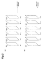
- FIG. 2 schematically shows the pre-existing reference images stored in the frame memory 104.
- FIG 2(a) shows the pre-existing reference images when frames are encoded in accordance with display order of moving picture signals.
- the reproduction images of frames 201, 202, 203, 204, and 205 are stored as pixel vectors y t , y t+1 , y t+2 , Y t+3 , and y t+4 (the indexes show time).
- encoding processing is carried out in the order from the frame 201 to the frame 205.
- the frame memory 104 stores the reproduction images of the frames 201 to 205 as the pre-existing reference images.
- FIG. 1 shows the pre-existing reference images when frames are encoded in accordance with display order of moving picture signals.
- the reproduction images of frames 201, 202, 203, 204, and 205 are stored as pixel vectors y t , y t+1 , y t+2
- FIG. 2(b) shows the pre-existing reference images when bidirectional prediction is carried out in detecting the motion amount.
- a frame 210 is encoded after encoding frames 207 to 209, 211 and 212.
- the frame memory 104 stores the reproduction images of the frames 207 to 209, 211 and 212 as the pre-existing reference images.
- the reference image generator 113 produces a new reference image by using a part of the pre-existing reference images stored in the frame memory 104 as described above.
- the reference image generator 113 forms a matrix y t t+4 composed of the pixel vectors y t , y t+1 , y t+2 , y t+3 , and y t+4 from the pixel vectors y t , y t+1 , y t+2 , y t+3 , and y t+4 of five pre-existing reference images in the frame memory 104 by using the following formula (1).
- Y t t + 4 y t y t + 1 y t + 2 y t + 3 y t + 4
- the reference image generator 113 carries out a singular value decomposition process on the matrix y t t+4 composed of the pre-existing reference images.
- QR decomposition represented by the following formula (2) can be employed.
- Y t t + 4 C ⁇ X t t + 4
- a matrix X t t+4 in formula (2) is expressed by the following formula (3).
- X t t + 4 x t x t + 1 x t + 2 x t + 3 x t + 4
- the reference image generator 113 obtains an observation matrix C and vectors x t , x t+1 , x t+2 , x t+3 , and x t+4 .
- the reference image generator 113 obtains a state transition matrix A from the vectors x t , x t+1 , x t+2 , x t+3 , and x t+4 by using the following formula (4).
- A X t + 1 t + 4 ⁇ X t t + 3 +
- the matrix X t+1 t+4 is given by the following formula (5), while the matrix X t t+3 is given by the following formula (6).
- the reference image generator 113 also obtains a state vector x t+5 by using the following formula (7) with the state transition matrix A obtained as described above.
- the reference image generator 113 produces a new reference image y" t+5 having a characteristic of a dynamic texture based on the state vector x t+5 and the observation matrix C as shown in the following formula (8).
- the observation matrix C is obtained from the reference images x t , x t+1 , x t+2 , x t+3 , and x t+4 as shown in formula (1), while new reference images added in the frame memory 104 by the reference image generator 113 in the past processes are not used.
- the new reference images having been added may be used for calculating the observation matrix C, for example, if the new reference images have high reliability.
- any methods may be used besides the singular value decomposition. The methods include eigenvalue decomposition, LU decomposition, and Cholesky decomposition.
- the prediction signal generator 103 produces a prediction signal with respect to a target pixel signal of a target block of a subsequent frame by using at least the new reference image.
- the prediction signal generator 103 may produce the prediction signal by using both the pre-existing reference images and the new reference image, or using the new reference image alone.
- the prediction signal generator 103 determines a reference block most similar to a pixel signal of a target block as a prediction signal for these reference images.
- An identifier to identify the reference image to which the prediction signal belongs and a motion vector indicating a displacement from a target block location are sent to a transmission side. (Details are described in " H.264 and MPEG-4 Video Compression", John Wiley & Sons, 2003 by Iain E. G.
- the prediction signal generator 103 specifies the pre-existing reference images or the new reference images in the frame memory 104 by referring to identification information attached to the pre-existing reference images or the new reference images. In this case, after a reproduction signal of a frame just before a target frame is stored in the frame memory 104, the prediction signal generator 103 produces a new reference image from the reference images of the latest five frames including the reproduction image. The method, however, is not limited to this.
- the prediction signal generator 103 may obtain the observation matrix C and the state vector x t+5 and thereafter directly produce a prediction signal of a target pixel signal by using them.
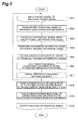
- the operation of the moving picture encoding device 1 is described in detail hereinafter and a moving picture encoding method according to the embodiment is explained with reference to FIG. 3 .
- the block divider 102 inputs a target pixel signal of a target block serving as an encoding target (step S01).
- the prediction signal generator 103 produces a prediction signal with respect to the target pixel signal by using a reference image stored in the frame memory 104 (step S02).
- the subtractor 105 produces a differential signal based on the target pixel signal and the prediction signal (step S03).
- the differential signal is transformed by the transformer 106 and quantized by the quantizer 107, resulting in an encoded differential signal being produced (step S04).
- the encoded differential signal is inverse-quantized by the inverse quantizer 108 and inverse-transformed by the inverse transformer 109, resulting in a decoded differential signal being reproduced (step S05). Furthermore, the adder 110 adds the prediction signal to the decoded differential signal to produce a reproduction signal (step S06). The reproduction signal is then stored in the frame memory 104 as a reference image (step S07). These processes on the target block are repeated on all target blocks in a target frame.
- the reference image generator 113 After one frame serving as the encoding target is encoded, the reference image generator 113 carries out the singular value decomposition process on a part of pre-existing reference images stored in the frame memory 104 to produce the observation matrix C and the state vector x t+5 (step S08). Next, the reference image generator 113 produces a new reference image based on the observation matrix C and the state vector x t+5 . The new reference image is then stored in the frame memory 104 as a reference image in encoding a subsequent frame (step S09). These processes for producing a new reference image are repeated on all moving pictures or a part of frames. Meanwhile, the encoded differential signal of the target frame is processed by the entropy encoder 111 to be included in compressed data, and output (step S10).
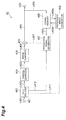
- FIG. 4 is a block diagram showing a structure of a moving picture decoding device 40 according to the first preferred embodiment of the present invention.
- the moving picture decoding device 40 shown in the diagram is provided with an input terminal (an input section) 401, a data analyzer (an input section) 402, an inverse quantizer (a decoding section) 403, an inverse transformer (a decoding section) 404, an adder (an adding section) 405, a prediction signal generator (a prediction signal generation section) 407, a frame memory (a storage section) 406, a reference image generator (a reference image generation section) 408 and an output terminal 409.
- an input terminal an input section
- a data analyzer an input section
- a decoding section inverse quantizer
- a decoding section a decoding section
- a decoding section inverse transformer
- an adder an adding section
- a prediction signal generator a prediction signal generation section
- a frame memory a storage section
- a reference image generator a reference image generation section
- the data analyzer 402 receives compressed data from the input terminal 401.
- the compressed data is compression-encoded data including an encoded differential signal.
- the data analyzer 402 analyses the compressed data and extracts from the data the encoded differential signal, a motion vector necessary to produce a prediction signal, and quantization parameters to carry out an inverse-quantization process.
- the data analyzer 402 outputs the extracted encoded differential signal and the quantization parameters to the inverse quantizer 403 through a line L402, and sends information relating to the motion vector to the prediction signal generator 407 through a line L410.
- the encoded differential signal is decoded by the inverse quantizer 403 and the inverse transformer 404, resulting in a differential signal being restored.
- the inverse quantizer 403 inverse-quantizes the encoded differential signal of a target block based on the quantization parameters.
- the inverse quantizer 403 outputs the inverse-quantized encoded differential signal to the inverse transformer 404 through a line L403.
- the inverse transformer 404 inverse-discrete-cosine-transforms the encoded differential signal input from the inverse quantizer 403 to produce a decoded differential signal.
- the inverse transformer 404 outputs the produced decoded differential signal to the adder 405 through a line L404.
- the prediction signal generator 407 produces a prediction signal with respect to the decoded differential signal of a processing target based on the motion vector extracted by the data analyzer 402 and a reference image referred from the frame memory 406.
- the produced prediction signal is sent to the adder 405 through a line L407.
- the adder 405 adds the prediction signal to the decoded differential signal decoded by the inverse transformer 404 to produce a reproduction signal of the target block.
- the adder 405 then stores the reproduction signal in the frame memory 406 as a reference image.
- the reproduction signal is transmitted to an external image display device (not shown) through the output terminal 409.
- the reference image generator 408 obtains the observation matrix C and the state vector x t+5 by the singular value decomposition process based on a part of pre-existing reference images stored in the frame memory 406 in the same manner of the reference image generator 113 of the moving picture encoding device 1 described above.
- the observation matrix C is produced by using the pre-existing reproduction images stored in the frame memory 406.
- the observation matrix C may be produced by using new reference images having been produced in the past processes together with the pre-existing reference images.
- the reference image generator 408 produces the new reference image y" t+5 having characteristics of a dynamic texture in the same manner of the reference image generator 113, and stores the new reference image in the frame memory 406 through a line L408b.
- the prediction signal generator 407 produces a prediction signal with respect to a target block of a subsequent frame based on at least the new reference image y" t+5 .
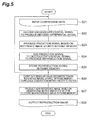
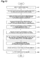
- the operation of the moving picture decoding device 40 is described in detail hereinafter and a moving picture decoding method according to the embodiment is explained with reference to FIG. 5 .
- the data analyzer 402 receives compressed data including an encoded differential signal and extracts the encoded differential signal, a motion vector, and quantization parameters from the compressed data (step S21).
- the encoded differential signal is decoded by the inverse quantizer 403 and the inverse transformer 404, resulting in a decoded differential signal being formed (step S22).
- the prediction signal generator 407 produces a prediction signal based on the motion vector and a reference image referred from the frame memory 406 (step S23).
- the adder 405 adds the prediction signal to the decoded differential signal to produce a reproduction signal (step S24).
- the reproduction signal is stored in the frame memory 406 as a reference signal (step S25).
- the reference image generator 408 carries out the singular value decomposition process on reference images stored in the frame memory 406 to obtain the observation matrix C and the state vector x t+5 (step S26).
- the reference image generator 408 then produces the new reference image y" t+5 by using the observation matrix C and the state vector x t+5 , and stores the new reference image in the frame memory 406 (step S27).
- the produced new reference image y" t+5 is used as a reference image for decoding a subsequent frame.
- the moving picture encoding device 1 and the moving picture decoding device 40 described above obtain the observation matrix C and the state vector x t+5 by using pre-existing reference images that have been already produced and stored in a memory to produce a new reference image based on the observation matrix C and the state vector x t+5 .
- the devices then produce a prediction signal with respect to a target pixel signal by using at least the new reference image. Consequently, a reference image suitable for a characteristic of a dynamic texture and not included in the pre-existing reference images can be newly produced. More specifically, the embodiment uses a characteristic that the dynamic texture is expressed by an autoregressive moving average model (ARMA) and produces from the pre-existing reference images, for example, an observation matrix and a state vector used for the model.
- ARMA autoregressive moving average model
- a reference image suitable for a characteristic of a dynamic texture and not included in the pre-existing reference images can be newly produced.
- This enables a prediction signal more similar to a dynamic texture in an encoding target image to be produced, and makes a differential signal small. Consequently, the data amount of a compressed moving picture can be effectively reduced.
- the prediction signal is produced from a plurality of candidate signals including the new reference image suitable for the dynamic texture together with the pre-existing reference images, the prediction signal more similar to the target pixel signal than the conventional prediction signal can be determined, thus enabling the differential signal to be further made small.
- a moving picture encoding program that causes a computer to operate as the moving picture encoding device 1 and a moving picture decoding program that causes a computer to operate as the moving picture decoding device 40 are described below.
- the moving picture encoding program and the moving picture decoding program according to the present invention are provided by being stored in a recording medium.
- the recording medium include recording media such as floppy disks (registered trademark), CD-ROMs, DVDs, and ROMs, and semiconductor memories.
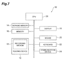
- FIG. 7 shows a hardware configuration of a computer for executing the program recorded in the recording medium.
- FIG. 8 is a perspective view of the computer for executing the program stored in the recording medium.
- the computer includes DVD players, set top boxes, and cell-phones each of which is provided with a CPU and software for processing and controlling.
- a computer 30 is provided with a reading device 12 such as a floppy disk drive (floppy disk is the registered trademark), a CD-ROM drive device, and a DVD drive device, a working memory (RAM) 14 including a resident operating system, a memory 16 that stores a program stored in a recording medium 10, a display device 18 such as a display, a mouse 20 and a keyboard 22 both of which are input devices, a communication device 24 that transmits and receives data and the like, and a CPU 26 that controls the execution of the program.
- the recording medium 10 is inserted into the reading device 12, the computer 30 becomes accessible to the moving picture encoding and decoding programs stored in the recording medium 10 from the reading device 12.
- the moving picture encoding program and the moving picture decoding program enable the computer 30 to operate as the moving picture encoding device and the moving picture decoding device of the present invention.
- the moving picture encoding program or the moving picture decoding program may be provided through a network as a computer data signal 41 superimposed on a carrier wave.
- the computer 30 stores to the memory 16 the moving picture encoding program or the moving picture decoding program that is received by the communication device 24, and can execute the moving picture encoding program or the moving picture decoding program.
- the moving picture encoding device 1 and the moving picture decoding device 40 may so operate that both or either one of the observation matrix C and the state vector x t+5 that are used in producing a new reference image is included in compressed data and transmitted to the moving picture decoding device 40 from the moving picture encoding device 1.
- a decoding side does not need to carry out the process for producing the observation matrix or the state vector. As a result, the decoding process is efficiently carried out.
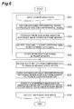
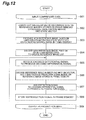
- FIG. 6 is a flow chart showing the operation of the moving picture decoding device 40 in this case.
- the processes from inputting compressed data to storing a reproduction image in the frame memory 406 are the same as those of step S21 to step S25 shown in FIG. 5 .
- the data analyzer 402 extracts and variable-length-decodes the state vector included in the compressed data to produce a decoded state vector.
- the decoded state vector is sent to the reference image generator 408 through a line L411 (step S36). This case is based on an assumption that the state vector is variable-length-encoded. If the state vector is compressed by a specific encoding method, the encoded state vector is decoded by a decoding method corresponding to the encoding method, and then the decoded state vector is sent to the reference image generator 408.
- the reference image generator 408 obtains the observation matrix C by referring to the frame memory 406 (step S37).
- the reference image generator 408 produces a new reference image by using the observation matrix C and the decoded state vector x t+5 sent from the data analyzer 402 (step S38). Lastly, a reproduction image of one frame is output from the output terminal 409 (step S39).
- the state vector x t+5 may be quantized and transmitted for compressing the data amount.
- a new reference image needs to be produced from the inverse-quantized state vector x t+5 and the observation matrix C in order to maintain the consistency of the encoding side and the decoding side.
- the state vector x t+5 used in producing a new reference image may be calculated by formula (7) or (8).
- the state vector x t+5 most suitable for the target frame y t+5 can be produced by multiplying the encoding target frame y" t+5 by the inverse matrix of the observation matrix C.
- All processes carried out by the reference image generator 408 may be performed by the prediction signal generator 407.
- the prediction signal generator 407 may obtain the observation matrix C and the state vector x t+5 by using pre-existing reference images stored in the frame memory 406 and directly produce a prediction signal based on the observation matrix C and the state vector x t+5 .
- both or either one of the observation matrix C and the state vector x t+5 may also be acquired from the encoding side.
- a signal having a characteristic of a dynamic texture is included in a part of target pixel signals in a target frame.
- the process for producing a new reference image may be carried out selectively on a partial region but not for the whole of the frame.
- a target block having a dynamic texture in a reproduction signal is identified by a block number, and the reference image generator 113 is set to be active (is activated) when a prediction signal with respect to the target block having the block number is produced.
- a second embodiment of the present invention is described with reference to the accompanying drawings.
- a moving picture encoding device and a moving picture decoding device according to the second embodiment partially differ from the moving picture encoding device and the moving picture decoding device according to the first embodiment.
- the different points are mainly described below.
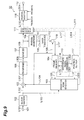
- FIG. 9 is a block diagram showing a structure of the moving picture encoding device according to the second embodiment of the present invention.
- a moving picture encoding device 50 shown in the diagram is provided with the input terminal (the input section) 101, the block divider (a dividing section) 102, the prediction signal generator (the prediction signal generation section) 103, the frame memory (the storage section) 104, the subtractor (the difference generation section) 105, the transformer (the encoding section) 106, the quantizer (the encoding section) 107, the inverse quantizer (the decoding section) 108, the inverse transformer (the decoding section) 109, the adder (the adding section) 110, the entropy encoder (an entropy encoding section) 111, the output terminal 112, the reference image generator (the reference image generation section) 113, a position setter (a position setting section) 117, and a position selector 118.
- the position setter 117 sets an insertion position of a new reference image in a reference image list that controls a plurality of reference images, and produces positional information that specifies the set insertion position.
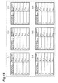
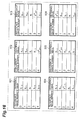
- the reference image list controls the plurality of reference images with reference image numbers assigned thereto. If the reproduction images of the frames 201 to 205 shown in FIG. 2 are the reference images, an exemplary list is shown in Table 901 in FIG 14 .
- Such reference image list is, for example, included in the prediction signal generator 103.
- the prediction signal generator 103 produces a prediction signal with respect to a target pixel signal of a target block by using a reference image selected from the reference images included in the reference image list.
- the reference image used in producing the prediction signal can be identified by the reference image number.
- the reference image numbers show a tendency that as the number decreases, the code quantity needed for encoding decreases. Therefore, setting a smaller reference image number to a reference image that is more frequently selected can improve encoding efficiency.
- the position setter 117 When setting the insertion position of the new reference image in the reference image list, the position setter 117 acquires information on pre-existing reference images from the frame memory 104 through a line L501 and information on the new reference image from the reference image generator 113 through a line L502 and sets the insertion position of the new reference image.
- the method of producing the new reference image in the reference image generator 113 is the same as that of the first embodiment. The description is, thus, omitted herein.
- the position setter 117 determines the insertion position of the new reference image in the reference image list (e.g., Table 901 in FIG. 14 ).
- the method of determining the insertion position by the position setter 117 may include a method in which the position is determined based on a new reference image selected rate in the past frames, and a method in which the position is determined based on a result of analyzing a texture signal rate in an image. The method, however, is not limited to them (a technique using rate distortion optimization is described later).
- the position setter 117 outputs the set or determined positional information to the prediction signal generator 103 through a line L503 and to the entropy encoder 111 through a line L504.
- the prediction signal generator 103 Upon receiving, through the line L503, the positional information (e.g., a reference image number in the reference image list) indicating the insertion position of the new reference image, the prediction signal generator 103 updates the reference image list based on the positional information. Specifically, when receiving the positional information indicating that the insertion position of the new reference image is reference image number 4, the prediction signal generator 103 provided with the reference image list shown in Table 901 in FIG. 14 updates the reference image list from Table 901 to Table 902 in FIG 14 . With the insertion of the new reference image, y t that is the oldest pre-existing reference image in encoded order is automatically excluded from the updated reference image list. Tables 903 to 906 in FIG. 14 are the updated reference image lists when pieces of positional information are input, the information indicating that the insertion positions of the new reference images are reference image numbers 3, 2, 1, and 0, respectively.
- a reference image list 911 shown in FIG. 15 is an example of the second reference image list.
- small reference image numbers i.e., 0 and 1 are given to the future frames relative to the encoding target frame in display order.
- Table 901 in FIG. 14 may be used. In this case, as shown in FIGS. 2(a) and 2(b) , five reference images before the encoding target frame (past images) and two reference images after the encoding target frame (future images), that is, a total of seven reference images need to be stored in the frame memory 104.
- the number of reference images is limited to five, five past frames in encoding order may be selected as the reference images of the first reference image list as shown in a reference image list 921 in FIG. 16 .
- the number of reference images is not limited. Any number (one or more) can be optionally set.
- the number of reference images may be determined in the encoding side and the decoding side in advance. Alternatively, in the encoding side, the number of reference images may be determined on a frame basis or a sequence basis and encoded to be sent to the decoding side.
- the position setter 117 sets respective pieces of positional information specifying the respective insertion positions of new reference images in two reference image lists (e.g., the reference image lists 911 and 921).
- the respective pieces of positional information specifying the insertion positions in the two reference image lists are output to the prediction signal generator 103 to update the reference image lists and to the entropy encoder 111 to perform entropy-encoding in the same manner described above.
- the position setter 117 may output a reference image excluded in updating a reference image list as reference image list formation information together with the positional information to the prediction signal generator 103 through the line L503 and to the entropy encoder 111 through the line L504 to perform encoding in the entropy encoder 111.
- the prediction signal generator 103 updates the reference image list based on the positional information and the reference image list formation information.
- the reference image list formation information may be produced and encoded such that a new reference image of a past frame is included in the reference image list instead of a new reference image of an encoding target frame.
- encoding is so carried out that the new reference image of the encoding target frame and the new reference image of the past frame are included together in the reference image list.
- This alternative way can be realized by encoding a combination of the frame number and the reference image type (a pre-existing reference image or a new reference image) for reference image numbers in the reference image list, for example.
- This method enables a reference image list to be composed of new reference images alone.
- the positional information specifying the insertion position of the new reference image instead shows that no new reference image is included in the reference image list.
- An example of the positional information includes a combination of a flag and the reference image number. The flag shows whether or not a new reference image is included in a reference image list, while the reference image number shows the insertion position of the new reference image. If the flag shows that a new reference image is not included, the reference image number is not encoded. This combination can widen the options of reference images and thus increase a degree of freedom. Particularly, in the bidirectional prediction, one reference image list alone includes a new reference image, while the other reference image list is composed of pre-existing reference images alone.
- the prediction signal generator 103 produces a prediction signal of a target block based on the updated reference image list after completion of updating the reference image list.
- the prediction signal generator 103 also detects the reference image number and the motion vector used for predicting the target block and outputs the reference image number and the motion vector to the entropy encoder 111 through the line L111. If a new reference image is used for prediction on the target block, a prediction signal of the target block may be produced without the output of the motion vector , that is, with a zero motion vector.
- the position selector 118 selects an insertion position of a new reference image in a reference image list by a rate distortion optimization method, and determines the position.
- the position selector 118 carries out the position setting, encoding, and local decoding processing, as described above, on each candidate of the insertion position of the new reference image (e.g., the reference image lists 902 to 906) by using the input terminal 101, the block divider 102, the prediction signal generator 103, the frame memory 104, the subtractor 105, the transformer 106, the quantizer 107, the inverse quantizer 108, the inverse transformer 109, the adder 110, the entropy encoder 111, and the position setter 117.
- the position selector 118 acquires encoded data of each candidate through the line L110 and calculates the code quantity.
- the position selector 118 acquires an input image of an encoding target frame from the input terminal 101 and a reproduction image of the encoding target frame from the adder 110, and calculates an encoding distortion (a mean square error) in each candidate.
- the position selector 118 calculates a sum of a code quantity that is multiplied by a weight coefficient determined by quantization accuracy and the encoding distortion in each candidate, and selects the insertion position of the new reference image having the minimum sum value.
- the position selector 118 outputs the encoded data of the selected candidate to the output terminal 112 through a line L505, and controls the frame memory 104 in such a manner that only the reproduction signal of the selected candidate becomes effective. In this way, the position selector 118 determines the insertion position of the new reference image.
- the position setter 117 determines the insertion position of the new reference image by a method such as the determination method based on the selected rate of new reference images as described above, instead of the rate distortion optimization method, the position selector 118 is not required.
- the operation of the moving picture encoding device 50 is described in detail hereinafter and a moving picture encoding method by a rate distortion optimization method is explained with reference to FIG. 10 .
- the processes of steps S45 to S50 described later are carried out on a plurality of past input images.
- the following processes are carried out on other encoding target signals before an encoding target signal is input.
- the prediction signal generator 103 produces a prediction signal with respect to a target pixel signal by using a plurality of reference images stored in the frame memory 104 (in the same manner of step S45 described later).
- the subtractor 105 produces a differential signal based on the target pixel signal and the prediction signal (in the same manner of step S46 described later).
- the differential signal is transformed into a frequency domain and quantized by the transformer 106 and the quantizer 107, resulting in an encoded differential signal being produced (in the same manner of step S47 described later).
- the encoded differential signal is inverse-quantized and inverse-transformed by the inverse quantizer 108 and the inverse transformer 109, resulting in a decoded differential signal being reproduced (in the same manner of step S48 described later).
- the adder 110 adds the prediction signal to the decoded differential signal to produce a reproduction signal (in the same manner of step S49 described later). Then, the reproduction signal is stored in the frame memory 104 as a reference image (in the same manner of step S50 described later).
- the target signal of the encoding target image is input (step S41).
- the reference image generator 113 carries out the singular value decomposition process on a part of pre-existing reference images stored in the frame memory 104 to produce the observation matrix C and the state vector x t+5 .
- the reference image generator 113 produces a new reference image based on the observation matrix C and the state vector x t+5 .
- the new reference image is then stored in the frame memory 104 as a reference image in encoding a subsequent frame (step S43). These processes for producing a new reference image are repeated on all moving pictures or a part of the frames. Both or either one of the produced observation matrix C and the state vector x t+5 may be transmitted to a receiving side.
- step S44 the position setter 117 produces positional information for setting the insertion position of the new reference image in a reference image list composed of reference images of pre-existing reproduction images (e.g., Table 901 in FIG. 14 , Table 911 in FIG. 15 , and Table 921 in FIG. 16 ), and outputs the positional information to the prediction signal generator 103.
- the prediction signal generator 103 receives the positional information and updates the reference image list based on the positional information to obtain the updated reference image list (e.g., Tables 902 to 906 in FIG. 14 , Tables 911 to 916 in FIG 15 , and Tables 921 to 926 in FIG. 16 ).
- step S45 a reference image and a motion vector used for the prediction on the target block are detected based on the reference image list updated in step S44.
- a prediction signal may be produced with a zero motion vector without sending of the motion vector.
- steps S46 to S50 are carried out as described above.
- step S51 the step flow is so controlled that the insertion position of the new reference image is changed in step S44 and the processes from step S45 to step S50 (basic encoding steps) are repeated in order to determine the insertion position of the new reference image in the updated reference image list.
- step S52 the code quantity and the encoding distortion (a mean square error of an input image and a reproduction image) in each of the repeated basic encoding steps are calculated, and a sum of the code quantity that is multiplied by a weight coefficient determined by quantization accuracy and the encoding distortion is obtained. Then, the setting position of the new reference image having the minimum sum value is selected and determined, and the frame memory 104 is configured in such a manner that only the result of the selected basic encoding step becomes effective.
- the code quantity and the encoding distortion a mean square error of an input image and a reproduction image
- step S53 encoded data including the insertion position of the new reference image selected in step 51 is output from the output terminal 112.
- the encoded data also includes positional information of the new reference image, the reference image numbers of the target blocks, the motion vector, and the encoded differential signal.
- the positional information specifying the insertion position of the new reference image is sent on a frame basis.
- the positional information specifying the insertion position of the new reference image may be determined on a large region basis and transmitted.
- the large region is a divided region obtained by dividing a picture plane and includes a plurality of blocks as a group.
- the prediction signal generator 103 may obtain the observation matrix C and the state vector x t+5 and directly produce a prediction signal.
- the observation matrix C and the state vector x t+5 are obtained by the singular value decomposition method. However, other methods may be employed besides the singular value decomposition method. If an updated reference image list includes no new reference image, the process by the reference image generator 113 does not need to be carried out for the target frame.
- the observation matrix C and the state vector x t+5 are obtained by the same method to produce a new reference image in the receiving side (the decoding side) as described later.
- the state vector x t+5 may be encoded and transmitted to reduce the process amount in the receiving side.
- the obtained state vector x t+5 is sent to the entropy encoder 111 through the line L117 to be entropy-encoded, and then the entropy-encoded state vector x t+5 is output and transmitted to the outside. If the prediction signal generator 103 obtains the state vector x t+5 , the state vector x t+5 is output and transmitted to the outside through the line L111.
- the state vector x t+5 is obtained by formula (7) and may also be obtained by formula (8).
- the state vector x t+5 most suitable for the target frame y" t+5 can be produced by multiplying the encoding target frame y" t+5 by the inverse matrix of the observation matrix C.
- the state vector x t+5 may be quantized and transmitted to reduce the data amount.
- a new reference image needs to be produced from the inverse-quantized state vector x t+5 and the observation matrix C in order to maintain the consistency of the sending side and the receiving side.
- the observation matrix C instead of sending the state vector x t+5 as described above, the observation matrix C also can be sent.
- Both the observation matrix C and the state vector x t+5 may be sent. There is a case where a signal having a characteristic of a dynamic texture is included in a part of a picture plane. In this case, the process for producing a new reference image may be carried out on a partial region but not for the whole of the frame.
- information specifying an insertion position of a new reference image is sent on a frame basis.
- the information specifying the insertion position of the new reference image may be sent on a large region basis.
- the large region is a divided region obtained by dividing a picture plane and includes a plurality of blocks as a group.
- the position setter 117 and the prediction signal generator 103 make up an updated reference image list for every large region.
- the prediction signal generator 103 selects a reference image based on an updated reference image list of a large region to which a target block belongs, and sends the reference image number to the entropy encoder 111.
- the definition of such a large region may be determined by the encoding and decoding sides in advance (e.g., a picture plane is divided in quarters to form four large regions).
- the formation of large regions may be determined by the encoding side, and encoded by the entropy encoder 111.
- This method enables the following processes to be carried out: a new reference image is added to a reference image list for a large region including a dynamic texture, while a reference image list for a large region including no dynamic texture is composed of pre-existing reference images alone.
- the insertion position of a new reference image in a reference image list is encoded.
- the insertion position may be determined by already-decoded information. For example, an insertion position of a new reference image in a reference image list may be automatically determined based on the selected rate of new reference images in frames having been encoded in the past processes.
- FIG. 10 is a block diagram showing the structure of the moving picture decoding device according to the second embodiment.
- a moving picture decoding device 60 shown in the diagram is provided with the input terminal (the input section) 401, an entropy decoder (an entropy decoding section) 410, the inverse quantizer (the decoding section) 403, the inverse transformer (the decoding section) 404, the adder (the adding section) 405, the prediction signal generator (the prediction signal generation section) 407, the frame memory (the storage section) 406, the reference image generator (the reference image generation section) 408 and the output terminal 409.
- the input terminal 401 receives compressed data including an encoded differential signal obtained by prediction-encoding a moving picture.
- compressed data includes data obtained by being processed in the moving picture encoding device 50 in FIG. 9 .
- the compressed data includes a motion vector necessary to produce a prediction signal, a reference image number to identify a reference image, quantization parameters to carry out an inverse-quantization process, data of the state vector x t+5 to produce a new reference image, and positional information specifying the insertion position of the new reference image, besides the encoded differential signal as described above. If the state vector x t+5 is produced by the moving picture decoding device 60, the state vector x t+5 may not be necessarily included in the compressed data.
- the entropy decoder 410 analyzes the input compressed data, restores the input compressed data to original numerical values and the like by entropy-decoding, and extracts the encoded differential signal and the like described above from the compressed data.
- the entropy decoder 410 outputs the extracted encoded differential signal and quantization parameters to the inverse quantizer 403 through the line L402, and also sends information relating to the motion vector to the prediction signal generator 407 through the line L410.
- the encoded differential signal is decoded by the inverse quantizer 403 and the inverse transformer 404, resulting in a differential signal being restored.
- the entropy decoder 410 also sends restored positional information specifying the insertion position of the new reference image to the prediction signal generator 407 through a line L412.
- the prediction signal generator 407 produces a prediction signal with respect to the decoded differential signal of a processing target.
- the prediction signal generator 407 Upon receiving the positional information specifying the insertion position of the new reference image from the entropy decoder 410, the prediction signal generator 407 updates the reference image list in the same manner of the prediction signal generator 103 of the moving picture encoding device 50. If no new reference image is included, the reference image list is not updated. If the compressed data includes reference image list formation information to produce a reference image list, the prediction signal generator 407 acquires the reference image list formation information decoded by the entropy decoder 410 through the line L412 so as to use the information to update the reference image list.
- Such reference image list formation information includes, for example, information on pre-existing reference image excluded from the reference image list as described above.
- the reference image list formation information includes a combination of the frame numbers and the reference image types (pre-existing reference image or new reference image) with respect to the respective reference image numbers in the reference image list, the reference image list can be explicitly updated.
- the prediction signal generator 407 accesses a reference image in the frame memory 406 based on the motion vector and the reference image number to produce a prediction signal of a target block serving as a decoding target.
- the prediction signal of the target block is produced from the new reference image with a zero motion vector.
- the prediction signal obtained in this way is sent to the adder 405 through the line L407.
- the adder 405 the prediction signal is added to the decoded differential signal to produce a reproduction signal.
- the reference image generator 408 obtains the observation matrix C and the state vector x t+5 by the singular value decomposition process based on a part of pre-existing reference images stored in the frame memory 406 in the same manner of the reference image generator 113 of the moving picture encoding device 50 described above.
- the compressed data includes the state vector x t+5
- the state vector x t+5 is acquired from the entropy decoder 410 through a line L411 and used.
- the state vector x t+5 included in the compressed data is entropy-encoded.
- the state vector x t+5 is compressed by a specific encoding method other than entropy-encoding
- the state vector x t+5 output from the entropy decoder 410 is decoded by a decoding process corresponding to the specific encoding method. Thereafter, the decoded state vector x t+5 is sent to the reference image generator 408.
- the observation matrix C is obtained by using a reproduction image.
- the observation matrix C may be obtained by using new reference images having been produced in the past processes together with the reproduction image.
- the reference image generator 408 produces the new reference image y" t+5 having a characteristic of a dynamic texture based on formula (8) with the observation matrix C and the state vector x t+5 in the same manner of the first embodiment.
- the produced new reference image y" t+5 is stored in the frame memory 406 through the line L408b.
- the prediction signal generator 407 produces a prediction signal of a target block of a subsequent frame based on at least one of the pre-existing reference image and the new reference image in the same manner of the prediction signal generator 103 of the moving picture encoding device 50.
- the prediction signal generator 407 can have the processing function of producing a new reference image of the reference image generator 408.
- the state vector x t+5 is sent to the prediction signal generator 407 through the line L410, and a prediction signal produced by the prediction signal generator 407 is directly sent to the adder 405.
- information specifying the insertion position of the new reference image is received on a frame basis.
- the information specifying the insertion position of the new reference image may be received on a large region basis.
- the large region is a divided region obtained by dividing a picture plane and includes a plurality of blocks as a group.
- the prediction signal generator 407 makes up an updated reference image list for every large region, and updates it.
- the prediction signal generator 407 selects a reference image based on the updated reference image list relating to a large region to which a target block belongs.
- the large region may be determined by the encoding and decoding sides in advance (e.g., a picture plane is divided in quarters to form four large regions).
- the formation of large regions may be decoded by the entropy decoder 410.
- the insertion position of the new reference image in the reference image list is decoded.
- the insertion position may be determined by the decoding side from already-decoded information. For example, an insertion position of a new reference image in a reference image list may be automatically determined based on the selected rate of new reference images in frames having been decoded in the past processes.
- the operation of the moving picture decoding device 60 is described in detail hereinafter and a moving picture decoding method in a case where the compressed data does not include the state vector x t+5 is explained with reference to FIG. 11 .
- the entropy decoder 410 receives compressed data including an encoded differential signal and extracts the encoded differential signal, a motion vector, a reference image number and quantization parameters from the compressed data.
- the encoded differential signal is decoded by the inverse quantizer 403 and the inverse transformer 404, resulting in a decoded differential signal being formed (step S65 described later).
- the motion vector and the reference image number necessary for producing a prediction signal of a target block serving as a decoding target are decoded.
- a prediction signal is produced based on a reference image stored in the frame memory together with the decoded motion vector and the reference image number (step S66 described later).
- the adder 405 adds the prediction signal to the decoded differential signal to produce a reproduction signal (step S67 described later).
- the reproduction signal is stored in the frame memory 406 as a reference signal (step S68 described later).
- step S61 the compressed data including the encoded differential signal serving as a decoding target is input (step S61).
- step S62 the singular value decomposition is carried out on reference images (reproduction images) stored in the frame memory 406 to produce the observation matrix C and the state vector x t+5 .
- the series of processes are carried out by using formulas (1) to (8) based on the observation matrix C and the state vector x t+5 so as to produce a new reference image.
- the produced new reference image is stored in the frame memory 406 (step S63).
- step S64 positional information is acquired from the compressed data to update a reference image list.
- the positional information specifies the insertion position of the new reference image in the reference image list (e.g., refer to Table 901 in FIG. 14 ) composed of reference images of pre-existing reproduction images.
- the updated reference image list (e.g., refer to Tables 902 to 906 in FIG. 14 ) is obtained.
- step S65 the encoded differential signal is decoded to produce a decoded differential signal.
- step S66 the reference image number and the motion vector are decoded.
- a prediction signal of the target block is produced from the reference image specified by the decoded reference image number and the motion vector. Thereafter, steps S67 and S68 are carried out. After the processes from step S65 to step S68 are repeated predetermined times (or until the compressed data is thoroughly input and the restoring process is completed), a reproduction image is output to the output terminal 409 (step S69).
- step S71, and S74 to S80 are the same as those of step S61, and S63 to S69 in FIG. 12 . The description thereof is omitted.
- step S72 the state vector x t+5 is extracted from the compressed data and decoded to produce a decoded state vector.
- step S73 the singular value decomposition is carried out on reference images (reproduction images) stored in the frame memory 406 to produce the observation matrix C. Then, a new reference image is produced based on the observation matrix C and the decoded state vector obtained in step S72 in the same manner of step S63 in FIG. 12 (step S74). The new reference image produced in this way is stored in the frame memory 406 as a reference image for decoding a subsequent frame.
- the moving picture encoding device 50 and the moving picture decoding device 60 described above use the characteristic that the dynamic texture is expressed by the autoregressive moving average model (ARMA), obtain the observation matrix C used in the model by using the pre-existing reference images having been already produced, and produce a new reference image based on the observation matrix C.
- ARMA autoregressive moving average model
- a reference image suitable for a characteristic of a dynamic texture and not included in the pre-existing reference images can be newly produced.
- This enables a prediction signal more similar to a dynamic texture in an encoding target image to be produced.
- the differential signal is made small and the data amount of a compressed moving picture can be effectively reduced. In other words, a dynamic texture can be efficiently encoded.
- the moving picture encoding device etc. encodes the position of the new reference image in the reference image list, thereby reducing the code quantity needed for selecting information of reference images.
- a moving picture encoding program and a moving picture decoding program that cause a computer to operate as the moving picture encoding device 50 and the moving picture decoding device 60 are the same as those of the first embodiment. The descriptions thereof are omitted.
- the present invention is directed to a moving picture encoding device, a moving picture decoding device, a moving picture encoding method, a moving picture decoding method, a moving picture encoding program, and a moving picture decoding program, and can reduce the data amount of a compressed moving picture by producing a prediction signal suitable for a moving picture including a dynamic texture.
Applications Claiming Priority (3)
| Application Number | Priority Date | Filing Date | Title |
|---|---|---|---|
| JP2008241128 | 2008-09-19 | ||
| JP2009104084A JP5680283B2 (ja) | 2008-09-19 | 2009-04-22 | 動画像符号化装置、動画像復号装置、動画像符号化方法、動画像復号方法、動画像符号化プログラム、及び動画像復号プログラム |
| EP09814538.6A EP2352295B1 (en) | 2008-09-19 | 2009-09-11 | Video coding using artificial reference frames |
Related Parent Applications (2)
| Application Number | Title | Priority Date | Filing Date |
|---|---|---|---|
| EP09814538.6A Division-Into EP2352295B1 (en) | 2008-09-19 | 2009-09-11 | Video coding using artificial reference frames |
| EP09814538.6A Division EP2352295B1 (en) | 2008-09-19 | 2009-09-11 | Video coding using artificial reference frames |
Publications (1)
| Publication Number | Publication Date |
|---|---|
| EP2838269A1 true EP2838269A1 (en) | 2015-02-18 |
Family
ID=42039517
Family Applications (2)
| Application Number | Title | Priority Date | Filing Date |
|---|---|---|---|
| EP20140185705 Ceased EP2838269A1 (en) | 2008-09-19 | 2009-09-11 | Video coding using artificial reference frames |
| EP09814538.6A Not-in-force EP2352295B1 (en) | 2008-09-19 | 2009-09-11 | Video coding using artificial reference frames |
Family Applications After (1)
| Application Number | Title | Priority Date | Filing Date |
|---|---|---|---|
| EP09814538.6A Not-in-force EP2352295B1 (en) | 2008-09-19 | 2009-09-11 | Video coding using artificial reference frames |
Country Status (6)
| Country | Link |
|---|---|
| US (1) | US9277238B2 (ja) |
| EP (2) | EP2838269A1 (ja) |
| JP (1) | JP5680283B2 (ja) |
| CN (1) | CN102027746B (ja) |
| TW (1) | TWI548265B (ja) |
| WO (1) | WO2010032693A1 (ja) |
Families Citing this family (16)
| Publication number | Priority date | Publication date | Assignee | Title |
|---|---|---|---|---|
| JP5680283B2 (ja) | 2008-09-19 | 2015-03-04 | 株式会社Nttドコモ | 動画像符号化装置、動画像復号装置、動画像符号化方法、動画像復号方法、動画像符号化プログラム、及び動画像復号プログラム |
| JP5368631B2 (ja) | 2010-04-08 | 2013-12-18 | 株式会社東芝 | 画像符号化方法、装置、及びプログラム |
| JP5982734B2 (ja) | 2011-03-11 | 2016-08-31 | ソニー株式会社 | 画像処理装置および方法 |
| JP2012253722A (ja) * | 2011-06-07 | 2012-12-20 | Sony Corp | 画像符号化装置と画像復号装置およびその方法とプログラム |
| KR101442127B1 (ko) * | 2011-06-21 | 2014-09-25 | 인텔렉추얼디스커버리 주식회사 | 쿼드트리 구조 기반의 적응적 양자화 파라미터 부호화 및 복호화 방법 및 장치 |
| JP5698644B2 (ja) * | 2011-10-18 | 2015-04-08 | 株式会社Nttドコモ | 動画像予測符号化方法、動画像予測符号化装置、動画像予測符号化プログラム、動画像予測復号方法、動画像予測復号装置及び動画像予測復号プログラム |
| US20130101014A1 (en) * | 2011-10-25 | 2013-04-25 | Microsoft Corporation | Layered Screen Video Encoding |
| JP6120490B2 (ja) | 2011-11-07 | 2017-04-26 | キヤノン株式会社 | 画像符号化装置、画像符号化方法及びプログラム、画像復号装置、画像復号方法及びプログラム |
| TW201334565A (zh) * | 2011-12-28 | 2013-08-16 | Jvc Kenwood Corp | 動態影像編碼裝置、動態影像編碼方法及動態影像編碼程式、以及動態影像解碼裝置、動態影像解碼方法及動態影像解碼程式 |
| WO2013109093A1 (ko) | 2012-01-19 | 2013-07-25 | 한국전자통신연구원 | 영상 부호화/복호화 방법 및 장치 |
| US9729870B2 (en) * | 2012-01-31 | 2017-08-08 | Apple Inc. | Video coding efficiency with camera metadata |
| JP5798539B2 (ja) * | 2012-09-24 | 2015-10-21 | 株式会社Nttドコモ | 動画像予測符号化装置、動画像予測符号化方法、動画像予測復号装置及び動画像予測復号方法 |
| CN102970542B (zh) * | 2012-11-30 | 2015-06-10 | 上海晨思电子科技有限公司 | 一种视频数据转换的方法、装置和智能电视 |
| KR101410837B1 (ko) * | 2013-09-10 | 2014-06-24 | 이에스이 주식회사 | 비디오 메모리의 모니터링을 이용한 영상 처리 장치 |
| CN104967453B (zh) * | 2015-06-24 | 2018-01-05 | 西北工业大学 | 基于fpga的多路循环数据压缩器和解压缩器以及方法 |
| CN104933670B (zh) * | 2015-07-02 | 2018-06-15 | 北京电子工程总体研究所 | 一种图像像素数据的存储方法及系统 |
Citations (4)
| Publication number | Priority date | Publication date | Assignee | Title |
|---|---|---|---|---|
| US6259739B1 (en) | 1996-11-26 | 2001-07-10 | Matsushita Electric Industrial Co., Ltd. | Moving picture variable bit rate coding apparatus, moving picture variable bit rate coding method, and recording medium for moving picture variable bit rate coding program |
| US20030076334A1 (en) * | 2001-10-11 | 2003-04-24 | Adriana Dumitras | Texture replacement in video sequences and images |
| US20070109409A1 (en) * | 2004-12-17 | 2007-05-17 | Sehoon Yea | Method and System for Processing Multiview Videos for View Synthesis using Skip and Direct Modes |
| WO2008008331A2 (en) * | 2006-07-11 | 2008-01-17 | Thomson Licensing | Methods and apparatus using virtual reference pictures |
Family Cites Families (12)
| Publication number | Priority date | Publication date | Assignee | Title |
|---|---|---|---|---|
| JPS60235528A (ja) * | 1984-05-08 | 1985-11-22 | Canon Inc | デ−タ圧縮方式 |
| EP0719049B1 (en) * | 1994-12-20 | 2003-05-28 | Matsushita Electric Industries Co., Ltd. | Method and apparatus for image coding |
| EP1518211A2 (en) * | 2000-12-22 | 2005-03-30 | Anthropics Technology Limited | Image processing system |
| US6909807B2 (en) * | 2001-06-28 | 2005-06-21 | Intel Corporation | Compression and synthesis of two dimensional images |
| ES2401991T3 (es) * | 2002-04-26 | 2013-04-26 | Ntt Docomo, Inc. | Dispositivo para la codificación de imágenes, procedimiento para la codificación de imágenes y programa para la codificación de imágenes |
| CN1312927C (zh) * | 2002-07-15 | 2007-04-25 | 株式会社日立制作所 | 动态图像编码方法及解码方法 |
| US7336803B2 (en) * | 2002-10-17 | 2008-02-26 | Siemens Corporate Research, Inc. | Method for scene modeling and change detection |
| FR2852773A1 (fr) * | 2003-03-20 | 2004-09-24 | France Telecom | Procedes et dispositifs de codage et de decodage d'une sequence d'images par decomposition mouvement/texture et codage par ondelettes |
| JP4415186B2 (ja) * | 2004-05-17 | 2010-02-17 | カシオ計算機株式会社 | 動画像符号化装置、動画像復号化装置、コーデック装置、および、プログラム |
| JP2008544766A (ja) * | 2005-05-12 | 2008-12-11 | ブラッコ イメージング エス.ピー.エー. | デジタル画像のピクセルまたはボクセルをコーディングするための方法、およびデジタル画像を処理するための方法 |
| AU2006338425B2 (en) * | 2006-02-13 | 2010-12-09 | Kabushiki Kaisha Toshiba | Moving image encoding/decoding method and device and program |
| JP5680283B2 (ja) | 2008-09-19 | 2015-03-04 | 株式会社Nttドコモ | 動画像符号化装置、動画像復号装置、動画像符号化方法、動画像復号方法、動画像符号化プログラム、及び動画像復号プログラム |
-
2009
- 2009-04-22 JP JP2009104084A patent/JP5680283B2/ja not_active Expired - Fee Related
- 2009-09-11 WO PCT/JP2009/065945 patent/WO2010032693A1/ja active Application Filing
- 2009-09-11 CN CN200980116976.2A patent/CN102027746B/zh not_active Expired - Fee Related
- 2009-09-11 EP EP20140185705 patent/EP2838269A1/en not_active Ceased
- 2009-09-11 EP EP09814538.6A patent/EP2352295B1/en not_active Not-in-force
- 2009-09-17 TW TW098131397A patent/TWI548265B/zh not_active IP Right Cessation
-
2011
- 2011-03-18 US US13/051,768 patent/US9277238B2/en not_active Expired - Fee Related
Patent Citations (4)
| Publication number | Priority date | Publication date | Assignee | Title |
|---|---|---|---|---|
| US6259739B1 (en) | 1996-11-26 | 2001-07-10 | Matsushita Electric Industrial Co., Ltd. | Moving picture variable bit rate coding apparatus, moving picture variable bit rate coding method, and recording medium for moving picture variable bit rate coding program |
| US20030076334A1 (en) * | 2001-10-11 | 2003-04-24 | Adriana Dumitras | Texture replacement in video sequences and images |
| US20070109409A1 (en) * | 2004-12-17 | 2007-05-17 | Sehoon Yea | Method and System for Processing Multiview Videos for View Synthesis using Skip and Direct Modes |
| WO2008008331A2 (en) * | 2006-07-11 | 2008-01-17 | Thomson Licensing | Methods and apparatus using virtual reference pictures |
Non-Patent Citations (9)
| Title |
|---|
| ADRIANA DUMITRAS ET AL: "An encoder-only texture replacement method for effective compression of entertainment movie sequences", 2002 IEEE INTERNATIONAL CONFERENCE ON ACOUSTICS, SPEECH, AND SIGNAL PROCESSING. PROCEEDINGS. (ICASSP). ORLANDO, FL, MAY 13 - 17, 2002; [IEEE INTERNATIONAL CONFERENCE ON ACOUSTICS, SPEECH, AND SIGNAL PROCESSING (ICASSP)], NEW YORK, NY : IEEE, US, 13 May 2002 (2002-05-13), pages IV - 3265, XP032015535, ISBN: 978-0-7803-7402-7, DOI: 10.1109/ICASSP.2002.5745350 * |
| ALEKSANDAR STOJANOVIC ET AL: "Dynamic texture synthesis for H.264/AVC inter coding", IMAGE PROCESSING, 2008. ICIP 2008. 15TH IEEE INTERNATIONAL CONFERENCE, IEEE, PISCATAWAY, NJ, USA, 12 October 2008 (2008-10-12), pages 1608 - 1611, XP031374325, ISBN: 978-1-4244-1765-0 * |
| BUDAGAVI M: "Video Compression using Blur Compensation", IMAGE PROCESSING,2005. ICIP 2005, IEEE, US, vol. 2, 11 September 2005 (2005-09-11), pages 882 - 885, XP010851195, ISBN: 978-0-7803-9134-5, DOI: 10.1109/ICIP.2005.1530197 * |
| CHUNBO ZHU ET AL: "Video coding with spatio-temporal texture synthesis and edge-based inpainting", MULTIMEDIA AND EXPO, 2008 IEEE INTERNATIONAL CONFERENCE ON, IEEE, PISCATAWAY, NJ, USA, 23 June 2008 (2008-06-23), pages 813 - 816, XP031312846, ISBN: 978-1-4244-2570-9 * |
| DUFAUX F ET AL: "Background mosaicking for low bit rate video coding", PROCEEDINGS OF THE INTERNATIONAL CONFERENCE ON IMAGE PROCESSING (ICIP) LAUSANNE, SEPT. 16 - 19, 1996; [PROCEEDINGS OF THE INTERNATIONAL CONFERENCE ON IMAGE PROCESSING (ICIP)], NEW YORK, IEEE, US, vol. 1, 16 September 1996 (1996-09-16), pages 673 - 676, XP010202155, ISBN: 978-0-7803-3259-1, DOI: 10.1109/ICIP.1996.559588 * |
| E. G. RICHARDSON: "H.264 and MPEG-4 Video Compression", 2003, JOHN WILEY & SONS |
| E. G. RICHARDSON: "H.264 and MPEG-4 Video Compression", 2003, JOHN WILEY & SONS, pages: 170 - 176,207- |
| GIANFRANCO DORETTO ET AL: "Spatially Homogeneous Dynamic Textures", 22 April 2004, COMPUTER VISION - ECCV 2004; [LECTURE NOTES IN COMPUTER SCIENCE;;LNCS], SPRINGER-VERLAG, BERLIN/HEIDELBERG, PAGE(S) 591 - 602, ISBN: 978-3-540-21983-5, XP019005856 * |
| SOATTO S ET AL: "Dynamic textures", PROCEEDINGS OF THE EIGHT IEEE INTERNATIONAL CONFERENCE ON COMPUTER VISION. (ICCV). VANCOUVER, BRITISH COLUMBIA, CANADA, JULY 7 - 14, 2001; [INTERNATIONAL CONFERENCE ON COMPUTER VISION], LOS ALAMITOS, CA : IEEE COMP. SOC, US, vol. 2, 7 July 2001 (2001-07-07), pages 439 - 446, XP010554121, ISBN: 978-0-7695-1143-6 * |
Also Published As
| Publication number | Publication date |
|---|---|
| US9277238B2 (en) | 2016-03-01 |
| TWI548265B (zh) | 2016-09-01 |
| EP2352295A4 (en) | 2012-03-28 |
| CN102027746B (zh) | 2014-03-26 |
| CN102027746A (zh) | 2011-04-20 |
| EP2352295A1 (en) | 2011-08-03 |
| TW201016021A (en) | 2010-04-16 |
| JP2010098710A (ja) | 2010-04-30 |
| EP2352295B1 (en) | 2014-11-12 |
| JP5680283B2 (ja) | 2015-03-04 |
| WO2010032693A1 (ja) | 2010-03-25 |
| US20110222601A1 (en) | 2011-09-15 |
Similar Documents
| Publication | Publication Date | Title |
|---|---|---|
| EP2352295B1 (en) | Video coding using artificial reference frames | |
| US8625916B2 (en) | Method and apparatus for image encoding and image decoding | |
| RU2652500C1 (ru) | Устройство кодирования видео с предсказанием, способ кодирования видео с предсказанием, программа кодирования видео с предсказанием, устройство декодирования видео с предсказанием, способ декодирования видео с предсказанием и программа декодирования видео с предсказанием | |
| JP3013698B2 (ja) | ベクトル量子化符号化装置と復号化装置 | |
| CN100544444C (zh) | 用于全景图像的运动估计和补偿的方法和设备 | |
| CN103748875A (zh) | 用于应用基于分区的滤波器的视频译码的方法和装置和存储媒体 | |
| JP2008278091A (ja) | 動画像記録方法及びその装置 | |
| KR20000052551A (ko) | 동화상 부호방법 및 부호장치와 동화상 부호 프로그램을기록하는 기록매체 | |
| EP1819173B1 (en) | Motion vector predictive encoding apparatus and decoding apparatus | |
| US20220417550A1 (en) | Method and apparatus for constructing motion information list in video encoding and decoding and device | |
| KR20140029369A (ko) | 화상 예측 부호화 장치, 화상 예측 부호화 방법, 화상 예측 부호화 프로그램, 화상 예측 복호 장치, 화상 예측 복호 방법, 및 화상 예측 복호 프로그램 | |
| US8897368B2 (en) | Image coding device, image coding method, image coding integrated circuit and image coding program | |
| JP5375697B2 (ja) | 動画像符号化装置、動画像復号装置、動画像符号化方法、及びプログラム | |
| JPH08205172A (ja) | 領域分割型動き予測回路、領域分割型動き予測回路内蔵画像符号化装置および領域分割型動き予測画像復号化装置 | |
| US20060204114A1 (en) | Multi-resolution motion estimator and method for estimating a motion vector | |
| JP2008072608A (ja) | 画像符号化装置及び画像符号化方法 | |
| JP2003125411A (ja) | 画像符号化装置、画像復号装置並びにその方法及び画像符号化プログラム、画像復号プログラム | |
| JP2015156704A (ja) | 動画像予測符号化装置、動画像予測符号化方法、動画像予測復号装置及び動画像予測復号方法 | |
| US20200329232A1 (en) | Method and device for encoding or decoding video signal by using correlation of respective frequency components in original block and prediction block | |
| JP2015039246A (ja) | 動画像予測符号化装置、動画像予測符号化方法、動画像予測符号化プログラム、動画像予測復号装置、動画像予測復号方法及び動画像予測復号プログラム |
Legal Events
| Date | Code | Title | Description |
|---|---|---|---|
| 17P | Request for examination filed |
Effective date: 20140922 |
|
| AC | Divisional application: reference to earlier application |
Ref document number: 2352295 Country of ref document: EP Kind code of ref document: P |
|
| AK | Designated contracting states |
Kind code of ref document: A1 Designated state(s): AT BE BG CH CY CZ DE DK EE ES FI FR GB GR HR HU IE IS IT LI LT LU LV MC MK MT NL NO PL PT RO SE SI SK SM TR |
|
| PUAI | Public reference made under article 153(3) epc to a published international application that has entered the european phase |
Free format text: ORIGINAL CODE: 0009012 |
|
| RBV | Designated contracting states (corrected) |
Designated state(s): AT BE BG CH CY CZ DE DK EE ES FI FR GB GR HR HU IE IS IT LI LT LU LV MC MK MT NL NO PL PT RO SE SI SK SM TR |
|
| 17Q | First examination report despatched |
Effective date: 20160127 |
|
| STAA | Information on the status of an ep patent application or granted ep patent |
Free format text: STATUS: THE APPLICATION HAS BEEN REFUSED |
|
| 18R | Application refused |
Effective date: 20171103 |