EP2838176A1 - Method for charging secondary battery - Google Patents
Method for charging secondary battery Download PDFInfo
- Publication number
- EP2838176A1 EP2838176A1 EP13800979.0A EP13800979A EP2838176A1 EP 2838176 A1 EP2838176 A1 EP 2838176A1 EP 13800979 A EP13800979 A EP 13800979A EP 2838176 A1 EP2838176 A1 EP 2838176A1
- Authority
- EP
- European Patent Office
- Prior art keywords
- charge
- rate
- charging
- secondary battery
- battery
- Prior art date
- Legal status (The legal status is an assumption and is not a legal conclusion. Google has not performed a legal analysis and makes no representation as to the accuracy of the status listed.)
- Granted
Links
Images

Classifications
-
- H—ELECTRICITY
- H02—GENERATION; CONVERSION OR DISTRIBUTION OF ELECTRIC POWER
- H02J—ELECTRIC POWER NETWORKS; CIRCUIT ARRANGEMENTS OR SYSTEMS FOR SUPPLYING OR DISTRIBUTING ELECTRIC POWER; SYSTEMS FOR STORING ELECTRIC ENERGY
- H02J7/00—Circuit arrangements for charging or discharging batteries or for supplying loads from batteries
- H02J7/90—Regulation of charging or discharging current or voltage
- H02J7/933—Regulation of charging or discharging current or voltage the cycle being controlled or terminated in response to electric parameters
-
- H—ELECTRICITY
- H01—ELECTRIC ELEMENTS
- H01M—PROCESSES OR MEANS, e.g. BATTERIES, FOR THE DIRECT CONVERSION OF CHEMICAL ENERGY INTO ELECTRICAL ENERGY
- H01M10/00—Secondary cells; Manufacture thereof
- H01M10/42—Methods or arrangements for servicing or maintenance of secondary cells or secondary half-cells
- H01M10/44—Methods for charging or discharging
- H01M10/446—Initial charging measures
-
- H—ELECTRICITY
- H02—GENERATION; CONVERSION OR DISTRIBUTION OF ELECTRIC POWER
- H02J—ELECTRIC POWER NETWORKS; CIRCUIT ARRANGEMENTS OR SYSTEMS FOR SUPPLYING OR DISTRIBUTING ELECTRIC POWER; SYSTEMS FOR STORING ELECTRIC ENERGY
- H02J7/00—Circuit arrangements for charging or discharging batteries or for supplying loads from batteries
-
- H—ELECTRICITY
- H02—GENERATION; CONVERSION OR DISTRIBUTION OF ELECTRIC POWER
- H02J—ELECTRIC POWER NETWORKS; CIRCUIT ARRANGEMENTS OR SYSTEMS FOR SUPPLYING OR DISTRIBUTING ELECTRIC POWER; SYSTEMS FOR STORING ELECTRIC ENERGY
- H02J7/00—Circuit arrangements for charging or discharging batteries or for supplying loads from batteries
- H02J7/02—Circuit arrangements for charging or discharging batteries or for supplying loads from batteries for charging batteries from AC mains by converters
- H02J7/04—Regulation of charging current or voltage
-
- H—ELECTRICITY
- H02—GENERATION; CONVERSION OR DISTRIBUTION OF ELECTRIC POWER
- H02J—ELECTRIC POWER NETWORKS; CIRCUIT ARRANGEMENTS OR SYSTEMS FOR SUPPLYING OR DISTRIBUTING ELECTRIC POWER; SYSTEMS FOR STORING ELECTRIC ENERGY
- H02J7/00—Circuit arrangements for charging or discharging batteries or for supplying loads from batteries
- H02J7/90—Regulation of charging or discharging current or voltage
- H02J7/96—Regulation of charging or discharging current or voltage in response to battery voltage
-
- H—ELECTRICITY
- H01—ELECTRIC ELEMENTS
- H01M—PROCESSES OR MEANS, e.g. BATTERIES, FOR THE DIRECT CONVERSION OF CHEMICAL ENERGY INTO ELECTRICAL ENERGY
- H01M10/00—Secondary cells; Manufacture thereof
- H01M10/05—Accumulators with non-aqueous electrolyte
- H01M10/052—Li-accumulators
-
- H—ELECTRICITY
- H01—ELECTRIC ELEMENTS
- H01M—PROCESSES OR MEANS, e.g. BATTERIES, FOR THE DIRECT CONVERSION OF CHEMICAL ENERGY INTO ELECTRICAL ENERGY
- H01M10/00—Secondary cells; Manufacture thereof
- H01M10/42—Methods or arrangements for servicing or maintenance of secondary cells or secondary half-cells
- H01M10/44—Methods for charging or discharging
-
- H—ELECTRICITY
- H02—GENERATION; CONVERSION OR DISTRIBUTION OF ELECTRIC POWER
- H02J—ELECTRIC POWER NETWORKS; CIRCUIT ARRANGEMENTS OR SYSTEMS FOR SUPPLYING OR DISTRIBUTING ELECTRIC POWER; SYSTEMS FOR STORING ELECTRIC ENERGY
- H02J7/00—Circuit arrangements for charging or discharging batteries or for supplying loads from batteries
- H02J7/90—Regulation of charging or discharging current or voltage
- H02J7/92—Regulation of charging or discharging current or voltage with prioritisation of loads or sources
-
- Y—GENERAL TAGGING OF NEW TECHNOLOGICAL DEVELOPMENTS; GENERAL TAGGING OF CROSS-SECTIONAL TECHNOLOGIES SPANNING OVER SEVERAL SECTIONS OF THE IPC; TECHNICAL SUBJECTS COVERED BY FORMER USPC CROSS-REFERENCE ART COLLECTIONS [XRACs] AND DIGESTS
- Y02—TECHNOLOGIES OR APPLICATIONS FOR MITIGATION OR ADAPTATION AGAINST CLIMATE CHANGE
- Y02E—REDUCTION OF GREENHOUSE GAS [GHG] EMISSIONS, RELATED TO ENERGY GENERATION, TRANSMISSION OR DISTRIBUTION
- Y02E60/00—Enabling technologies; Technologies with a potential or indirect contribution to GHG emissions mitigation
- Y02E60/10—Energy storage using batteries
Definitions
- the present invention relates to a charging method of a secondary battery and, more particularly, to a charging method of a secondary battery including a first charging step of charging the secondary battery at a first C-rate from an initial charge voltage to a first charge voltage and a second charging step of charging the secondary battery to a target voltage while gradually decreasing a C-rate within a range not exceeding the first C-rate after the voltage of the secondary battery reached the first charge voltage.
- the secondary batteries may be recharged after being discharged such that the secondary batteries can be continuously used.
- the secondary batteries have different performances based on charge and discharge states. For this reason, efforts have been made to improve a charging method of the secondary batteries such that the performance of the secondary batteries can be enhanced.
- FIG. 1 is a view showing a relationship between a charge current and a charge voltage in a conventional constant current (CC) - constant voltage (CV) charging method (hereinafter, referred to a CC - CV charging method), which is generally used as the charging method of the secondary battery as described above.
- the CC - CV charging method is a method of charging the secondary battery at the maximum current until voltage of the secondary battery reaches a predetermined battery voltage and charging the secondary battery while gradually decreasing the charging current after the voltage of the secondary battery reaches the predetermined battery voltage.
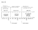
- FIG. 2 is a view showing a relationship between a charge period per step shown in FIG. 1 and a charge time.
- the battery is charged with a constant current until the voltage of the battery voltage is increased to a charge limit voltage.
- the battery is saturated and the battery is charged while the charge current is gradually decreased.
- the voltage of the battery voltage reaches the maximum battery voltage.
- auxiliary charge is carried out for the battery based on the voltage of the battery.
- overcharge using overvoltage is not possible and trickle charge may damage the battery.
- auxiliary charge is carried out while no trickle charge is applied.
- the trickle charge is a method of continuously supplying a charge current having a size approximate to that of a self discharge current to a storage cell such that the storage cell always remains charged in a case in which the storage cell is used as an emergency electrode.
- a constant current charge period (step 1), the battery is charged with a low constant current having a rate of 0.5 C or less for about one hour.
- a topping charge period (step 2) after the constant current charge period is relatively long.
- time or current is sensed to control the completion of charge. In the conventional CC - CV charging method, therefore, a C-rate is directly proportional to time.
- a charge rate is about 85 % or less when the battery is charged for 100 minutes. In order to achieve a charge rate of at least 90 %, therefore, it is necessary to charge the battery for 130 minutes or more. Consequently, much time is needed to charge the battery.
- the performance of the battery is deteriorated in a case in which a high rate charge current is supplied to the battery in order to improve a charge speed.
- the inventors of the present application have developed a charging method of a secondary battery including a first charging step of charging the secondary battery at a first C-rate from an initial charge voltage to a first charge voltage and a second charging step of charging the secondary battery to a target voltage while gradually decreasing a C-rate within a range not exceeding the first C-rate after the voltage of the secondary battery reached the first charge voltage and have found that, in a case in which the charging method of the present invention is applied, it is possible to restrain deterioration of the battery, thereby improving lifespan characteristics of the battery.
- the present invention has been completed based on these findings.
- a charging method of a secondary battery including a first charging step of charging the secondary battery at a first C-rate from an initial charge voltage to a first charge voltage and a second charging step of charging the secondary battery to a target voltage while gradually decreasing a C-rate within a range not exceeding the first C-rate after the voltage of the secondary battery reached the first charge voltage.
- the C-rate is a current rate, which is a unit used to set a current value and to estimate or indicate a possible use time of a battery under various conditions of use during charge and discharge of the battery. A charge or discharge time is divided by a rated capacity of the battery to calculate charge and discharge current values.
- the unit of the C-rate is C, which is defined as represented by Equation 1 below.
- C - rate C Charge and discharge current / Rated capacity of the battery
- a conventional constant current (CC) - constant voltage (CV) charging method of a secondary battery has a problem in that, in a case in which a high current is supplied to the secondary battery to increase a charge speed, deterioration of the secondary battery is accelerated and, in a case in which the charge speed is decreased, a charge quantity is reduced.
- the secondary battery is charged using a constant current charging method during a constant current charge period and a low constant current is supplied to the secondary battery when the secondary battery is charged during a constant voltage charge period such that the secondary battery is kept charged using the constant current charging method. That is, in a case in which voltage reaches a specific level or current starts to be decreased from a specific time with the result that it is not possible to continuously supply a constant current to the secondary battery, a low current is supplied to the secondary battery such that the secondary battery is charged at the next step.
- a charge speed per unit time may be lower than in the conventional CC - CV charging method on the assumption that the same C-rate is applied at the first charging step.
- the difference between the charge speeds is little, whereas a high voltage time may be reduced. Consequently, it is possible to restrain deterioration of the secondary battery, which is preferable.
- the first C-rate of the first charging step may have various ranges based on various factors, such as capacity and loading, of the battery.
- the first C-rate of the first charging step may have a range from 3C to 6C for a 15 to 20 Ah level battery.
- the first C-rate of the first charging step is 6C. If the C-rate is too small, a charge time is increased, which is not preferable. If the C-rate is too large, on the other hand, a charge quantity is decreased and deterioration of the battery is accelerated, which is also not preferable.
- the C-rate may be set to a lower value than that of the battery according to the present invention.
- the gradual decreasing of the C-rate in the second charging step may include stepwise decreasing the C-rate in proportion to the charging time.
- a charge rate per unit time may be lower than in the conventional CC - CV charging method.
- the difference between the charge rates is little, whereas it is possible to restrain deterioration of the battery, which is preferable.
- the decreasing of the C-rate may include stepwise decreasing the C-rate within a range from 3C to 1C.
- the decreasing of the C-rate may include stepwise decreasing the C-rate in order of 3C, 2C, and 1C.
- the initial charge voltage is voltage of the battery before being charged.
- the first charge voltage may have a range from 4.080 V to 4.095 V and the target voltage may have a range from 4.090 V to 4.100 V within a range equal to or greater than the first charge voltage.
- the C-rate may be changed without a time difference. Consequently, it is possible to reduce a charge time.
- the charging method according to the present invention may be applied to a lithium secondary battery.
- the secondary battery may be a lithium secondary battery.
- Example 1 of Table 1 it can be seen from Example 1 of Table 1 above that, in a case in which the stepwise charging method according to the present invention is used, it is possible to increase the charge quantity of the battery without great loss due to the charge time. Consequently, it is possible to reduce a high voltage time, thereby improving lifespan characteristics of the battery while preventing deterioration of the battery.
- Example 2 The batteries of Examples 2 to 5 and Comparative examples 5 to 8 were charged at a temperature of 25°C under the same conditions as in Table 2 and then discharged under a 2C CC condition. Charge and discharge energies of the batteries obtained through 2000 cycle charge and discharge with a rest time of 10 minutes after charge and discharge were compared to measure a deterioration rate of the batteries.
- Example 2 6.36 67.667
- Example 3 6.41 67.935
- Example 4 6.13 59.443
- Example 5 7.50 62.186 Comparative example 5 4.25 50.567 Comparative example 6 6.04 67.132 Comparative example 7 8.64 68.887 Comparative example 8 7.04 59.606
- the total charge and discharge energy of the battery of Example 3 is similar to that of the battery of Comparative example 7.
- the deterioration rate of the battery of Example 3 is about 25 % less than that of the battery of Comparative example 7.
- the lifespan of the batteries charged by stepwise 6C CC charging is about 25 % greater than that of the batteries charged by CC - CV charging.
Landscapes
- Engineering & Computer Science (AREA)
- Power Engineering (AREA)
- Manufacturing & Machinery (AREA)
- Chemical & Material Sciences (AREA)
- Chemical Kinetics & Catalysis (AREA)
- Electrochemistry (AREA)
- General Chemical & Material Sciences (AREA)
- Secondary Cells (AREA)
- Charge And Discharge Circuits For Batteries Or The Like (AREA)
Abstract
Description
- The present invention relates to a charging method of a secondary battery and, more particularly, to a charging method of a secondary battery including a first charging step of charging the secondary battery at a first C-rate from an initial charge voltage to a first charge voltage and a second charging step of charging the secondary battery to a target voltage while gradually decreasing a C-rate within a range not exceeding the first C-rate after the voltage of the secondary battery reached the first charge voltage.
- In recent years, as mobile devices, such as a portable computer, a mobile phone, and a camera, have been increasingly developed, and the demand for such mobile devices has increased, the demand for secondary batteries has also sharply increased as an energy source for the mobile devices. Among such secondary batteries is a lithium secondary battery having a high energy density and operation potential, a long cycle lifespan, and a low self discharge rate, into which much research has been carried out and which is now commercialized and widely used.
- The secondary batteries may be recharged after being discharged such that the secondary batteries can be continuously used. However, the secondary batteries have different performances based on charge and discharge states. For this reason, efforts have been made to improve a charging method of the secondary batteries such that the performance of the secondary batteries can be enhanced.
-
FIG. 1 is a view showing a relationship between a charge current and a charge voltage in a conventional constant current (CC) - constant voltage (CV) charging method (hereinafter, referred to a CC - CV charging method), which is generally used as the charging method of the secondary battery as described above. As shown inFIG. 1 , the CC - CV charging method is a method of charging the secondary battery at the maximum current until voltage of the secondary battery reaches a predetermined battery voltage and charging the secondary battery while gradually decreasing the charging current after the voltage of the secondary battery reaches the predetermined battery voltage. -
FIG. 2 is a view showing a relationship between a charge period per step shown inFIG. 1 and a charge time. At a first step, the battery is charged with a constant current until the voltage of the battery voltage is increased to a charge limit voltage. When the voltage of the battery voltage is increased to the charge limit voltage, at a second step, the battery is saturated and the battery is charged while the charge current is gradually decreased. At this time, the voltage of the battery voltage reaches the maximum battery voltage. Subsequently, auxiliary charge is carried out for the battery based on the voltage of the battery. For a lithium ion battery, overcharge using overvoltage is not possible and trickle charge may damage the battery. For this reason, auxiliary charge is carried out while no trickle charge is applied. (The trickle charge is a method of continuously supplying a charge current having a size approximate to that of a self discharge current to a storage cell such that the storage cell always remains charged in a case in which the storage cell is used as an emergency electrode.) - During a constant current charge period (step 1), the battery is charged with a low constant current having a rate of 0.5 C or less for about one hour. As a result, a topping charge period (step 2) after the constant current charge period is relatively long. In addition, time or current is sensed to control the completion of charge. In the conventional CC - CV charging method, therefore, a C-rate is directly proportional to time.
- In the conventional charging method as described above, a charge rate is about 85 % or less when the battery is charged for 100 minutes. In order to achieve a charge rate of at least 90 %, therefore, it is necessary to charge the battery for 130 minutes or more. Consequently, much time is needed to charge the battery.
- Furthermore, in the conventional charging method, the performance of the battery is deteriorated in a case in which a high rate charge current is supplied to the battery in order to improve a charge speed.
- In recent years, therefore, much research has been carried out into a charging method that is capable of stably charging a battery within a shorter time while reducing a deterioration rate of the battery and, in addition, there is a high necessity for an improved charging method.
- Therefore, the present invention has been made to solve the above problems and other technical problems that have yet to be resolved.
- As a result of a variety of extensive and intensive studies and experiments to solve the problems as described above, the inventors of the present application have developed a charging method of a secondary battery including a first charging step of charging the secondary battery at a first C-rate from an initial charge voltage to a first charge voltage and a second charging step of charging the secondary battery to a target voltage while gradually decreasing a C-rate within a range not exceeding the first C-rate after the voltage of the secondary battery reached the first charge voltage and have found that, in a case in which the charging method of the present invention is applied, it is possible to restrain deterioration of the battery, thereby improving lifespan characteristics of the battery. The present invention has been completed based on these findings.
- In accordance with one aspect of the present invention, the above and other technical problems can be solved by the provision of a charging method of a secondary battery including a first charging step of charging the secondary battery at a first C-rate from an initial charge voltage to a first charge voltage and a second charging step of charging the secondary battery to a target voltage while gradually decreasing a C-rate within a range not exceeding the first C-rate after the voltage of the secondary battery reached the first charge voltage.
- The C-rate is a current rate, which is a unit used to set a current value and to estimate or indicate a possible use time of a battery under various conditions of use during charge and discharge of the battery. A charge or discharge time is divided by a rated capacity of the battery to calculate charge and discharge current values. The unit of the C-rate is C, which is defined as represented by Equation 1 below.

- As previously described, a conventional constant current (CC) - constant voltage (CV) charging method of a secondary battery has a problem in that, in a case in which a high current is supplied to the secondary battery to increase a charge speed, deterioration of the secondary battery is accelerated and, in a case in which the charge speed is decreased, a charge quantity is reduced.
- In the charging method of the present invention, on the other hand, the secondary battery is charged using a constant current charging method during a constant current charge period and a low constant current is supplied to the secondary battery when the secondary battery is charged during a constant voltage charge period such that the secondary battery is kept charged using the constant current charging method. That is, in a case in which voltage reaches a specific level or current starts to be decreased from a specific time with the result that it is not possible to continuously supply a constant current to the secondary battery, a low current is supplied to the secondary battery such that the secondary battery is charged at the next step.
- In a case in which the above charging method is applied, a charge speed per unit time may be lower than in the conventional CC - CV charging method on the assumption that the same C-rate is applied at the first charging step. However, the difference between the charge speeds is little, whereas a high voltage time may be reduced. Consequently, it is possible to restrain deterioration of the secondary battery, which is preferable.
- The first C-rate of the first charging step may have various ranges based on various factors, such as capacity and loading, of the battery. In a preferred example, the first C-rate of the first charging step may have a range from 3C to 6C for a 15 to 20 Ah level battery. Preferably, the first C-rate of the first charging step is 6C. If the C-rate is too small, a charge time is increased, which is not preferable. If the C-rate is too large, on the other hand, a charge quantity is decreased and deterioration of the battery is accelerated, which is also not preferable.
- Although the same C-rate is given, a current quantity may be greatly increased for a high-capacity battery and cycle characteristics may be lowered for a battery having a high loading value. In the above batteries, therefore, the C-rate may be set to a lower value than that of the battery according to the present invention.
- In the charging method according to the present invention, the gradual decreasing of the C-rate in the second charging step may include stepwise decreasing the C-rate in proportion to the charging time. In a case in which the constant current charge period is set stepwise and the C-rate is reduced stepwise as described above, a charge rate per unit time may be lower than in the conventional CC - CV charging method. However, the difference between the charge rates is little, whereas it is possible to restrain deterioration of the battery, which is preferable.
- The decreasing of the C-rate may include stepwise decreasing the C-rate within a range from 3C to 1C. In a preferred example, the decreasing of the C-rate may include stepwise decreasing the C-rate in order of 3C, 2C, and 1C.
- The initial charge voltage is voltage of the battery before being charged. Those skilled in the art may arbitrarily set a range of the first charge voltage in consideration of conditions, such as charge performance and charge time, of the battery. For example, the first charge voltage may have a range from 4.080 V to 4.095 V and the target voltage may have a range from 4.090 V to 4.100 V within a range equal to or greater than the first charge voltage.
- In the charging method according to the present invention, the C-rate may be changed without a time difference. Consequently, it is possible to reduce a charge time.
- The charging method according to the present invention may be applied to a lithium secondary battery.
- In accordance with another aspect of the present invention, there is provided a secondary battery charged using the charging method as described above. The secondary battery may be a lithium secondary battery.
- The above and other objects, features and other advantages of the present invention will be more clearly understood from the following detailed description taken in conjunction with the accompanying drawings, in which:
-
FIG. 1 is a view showing a relationship between a charge current and a charge voltage in a conventional constant current (CC) - constant voltage (CV) charging method of a lithium secondary battery; and -
FIG. 2 is a view showing a relationship between a charge period per step shown inFIG. 1 and a charge time. - Now, the present invention will be described in more detail with reference to the following examples. These examples are provided only for illustration of the present invention and should not be construed as limiting the scope and spirit of the present invention.
- Charge times and charge quantities based on constant current (CC) charging results of Example 1 and Comparative examples 1 to 4 at a temperature of 30°C are shown in Table 1 below.
[Table 1] 30 °C CC charging Charge time (min) Charge quantity (Ah) (Percent of 11.2 Ah) Example 1 6C (4.085V) 6C (4.085V) -
3C (4.085V) -
2C (4.085V) -
1C (4.091V)15 9.52 (85 %) Comparative example 1 1C (15A), (4.091V) 40 10 (89 %) Comparative example 2 2C (30A), (4.091V) 18 9 (80 %) Comparative example 3 3C (45A), (4.091V) 11 8 (71 %) Comparative example 4 6C (90A), (4.091V) 4 5.3 (47 %) - It can be seen from Example 1 of Table 1 above that, in a case in which the stepwise charging method according to the present invention is used, it is possible to increase the charge quantity of the battery without great loss due to the charge time. Consequently, it is possible to reduce a high voltage time, thereby improving lifespan characteristics of the battery while preventing deterioration of the battery.
- Charge times and charge quantities based on CC charging results of Examples 2 to 5 and Comparative example 5 and constant current (CC) - constant voltage (CV) charging results of Comparative examples 6 to 8 at a temperature of 25°C are shown in Table 2 below.
[Table 2] 25°C CC charging (Examples 2 to 5 and Comparative example 5) Charge time (min) Charge quantity (Ah) (Percent of maximum charge quantity 11.6 Ah) CC - CV charging (Comparative examples 6 to 8) Example 2 3C (4.085V) - 2C (4.085V) - 1C (4.091V) 17.04 9.638 (83.09 %) Example 3 6C (4.085V - 3C (4.085V) - 2C (4.085V) - 1C (4.091V) 14.40 9.644 (83.14 %) Example 4 6C (4.085V - 3C (4.085V) - 2C (4.091V) 9.48 8.589 (74.04 %) Example 5 6C (4.091V) - 3C (4.091V) - 2C (4.091V) - 1C (4.091V) 13.73 9.810 (84.57 %) Comparative example 5 3C CC (4.091V) 9.61 7.208 (62.14 %) Comparative example 6 3CCC - CV(1C cut), (4.091V) 14.80 9.533 (82.18 %) Comparative example 7 6C CC - CV (1C cut), (4.091V) 10.82 9.954(85.81%) Comparative example 8 6C CC - CV (2C cut), (4.091V) 7.70 8.687 (74.89 %) - It can be seen from Table 2 above that the batteries according the examples of the present invention charged using the stepwise charging method have longer charge times than the batteries according the comparative examples charged using the CC - CV charging method but the difference in the charge times is little and that, in a case in which the batteries have the same cutting C-rate, the difference in the charge quantities of the batteries of the examples and the comparative examples is little.
- In addition, comparison between the battery of Example 1 and the battery of Example 3 of Table 2 reveals that a charge rate is lowered with the decrease of temperature. This is because ion transfer speed is lowered with the decrease of temperature and, therefore, charging is insufficiently carried out. Except the temperature, the battery of Example 1 and the battery of Example 3 have the same conditions. The battery of Example 1 and the battery of Example 3 may have different maximum charge quantities due to deterioration of the batteries during the experiment but the difference between the maximum charge quantities is little.
- The batteries of Examples 2 to 5 and Comparative examples 5 to 8 were charged at a temperature of 25°C under the same conditions as in Table 2 and then discharged under a 2C CC condition. Charge and discharge energies of the batteries obtained through 2000 cycle charge and discharge with a rest time of 10 minutes after charge and discharge were compared to measure a deterioration rate of the batteries.
[Table 3] 25°C Deterioration rate (%) Total charge and discharge energy (KWh) Example 2 6.36 67.667 Example 3 6.41 67.935 Example 4 6.13 59.443 Example 5 7.50 62.186 Comparative example 5 4.25 50.567 Comparative example 6 6.04 67.132 Comparative example 7 8.64 68.887 Comparative example 8 7.04 59.606 - It can be seen FIG. Table 3 above that the battery of Comparative example 7 CC - CV charged at 6C has the highest deterioration rate. However, in a case in which a high voltage and a high current are supplied to the battery as in Example 5 although stepwise charging is carried out, the deterioration rate of the battery is increased with the result that the lifespan characteristics of the battery may be lowered.
- Meanwhile, the total charge and discharge energy of the battery of Example 3 is similar to that of the battery of Comparative example 7. However, the deterioration rate of the battery of Example 3 is about 25 % less than that of the battery of Comparative example 7. As can be seen from Table 2 above, the lifespan of the batteries charged by stepwise 6C CC charging is about 25 % greater than that of the batteries charged by CC - CV charging.
- At 3C charging, a great effect is not obtained. This is because 16 Ah level batteries are tested with the result that there are no problems until the batteries are 6C charged. For 30 Ah level batteries for BE, however, it is necessary to reduce a C-rate during high speed charge of the batteries. In this case, therefore, it is expected that a desired effect will be obtained.
- Although the preferred embodiments of the present invention have been disclosed for illustrative purposes, those skilled in the art will appreciate that various modifications, additions and substitutions are possible, without departing from the scope and spirit of the invention as disclosed in the accompanying claims.
- As is apparent from the above description, in a case in which the charging method of the present invention is applied, it is possible to restrain deterioration of a battery without great loss due to a charge time, thereby improving lifespan characteristics of the battery.
Claims (12)
- A charging method of a secondary battery comprising:a first charging step of charging the secondary battery at a first C-rate from an initial charge voltage to a first charge voltage; anda second charging step of charging the secondary battery to a target voltage while gradually decreasing a C-rate within a range not exceeding the first C-rate after the voltage of the secondary battery reached the first charge voltage.
- The charging method according to claim 1, wherein the first C-rate of the first charging step has a range from 3C to 6C.
- The charging method according to claim 1, wherein the first C-rate of the first charging step is 6C.
- The charging method according to claim 1, wherein the gradual decreasing of the C-rate in the second charging step comprises stepwise decreasing the C-rate in proportion to a charge time.
- The charging method according to claim 4, wherein the decreasing of the C-rate comprises stepwise decreasing the C-rate within a range from 3C to 1C.
- The charging method according to claim 5, wherein the decreasing of the C-rate comprises stepwise decreasing the C-rate in order of 3C, 2C, and 1C.
- The charging method according to claim 1, wherein the first charge voltage has a range from 4.080 V to 4.095 V.
- The charging method according to claim 1, wherein the C-rate is changed without a time difference.
- The charging method according to claim 1, wherein the target voltage has a range from 4.090 V to 4.100 V within a range equal to or greater than the first charge voltage.
- The charging method according to claim 1, wherein the secondary battery is a lithium secondary battery.
- A secondary battery charged using a charging method according to claim 1.
- The secondary battery according to claim 11, wherein the secondary battery is a lithium secondary battery.
Applications Claiming Priority (2)
| Application Number | Priority Date | Filing Date | Title |
|---|---|---|---|
| KR20120060773 | 2012-06-07 | ||
| PCT/KR2013/005010 WO2013183952A1 (en) | 2012-06-07 | 2013-06-07 | Method for charging secondary battery |
Publications (3)
| Publication Number | Publication Date |
|---|---|
| EP2838176A1 true EP2838176A1 (en) | 2015-02-18 |
| EP2838176A4 EP2838176A4 (en) | 2015-06-03 |
| EP2838176B1 EP2838176B1 (en) | 2017-06-07 |
Family
ID=49712286
Family Applications (1)
| Application Number | Title | Priority Date | Filing Date |
|---|---|---|---|
| EP13800979.0A Active EP2838176B1 (en) | 2012-06-07 | 2013-06-07 | Method for charging secondary battery |
Country Status (6)
| Country | Link |
|---|---|
| US (1) | US9490642B2 (en) |
| EP (1) | EP2838176B1 (en) |
| JP (1) | JP6096284B2 (en) |
| KR (1) | KR101494156B1 (en) |
| CN (1) | CN104335445B (en) |
| WO (1) | WO2013183952A1 (en) |
Cited By (2)
| Publication number | Priority date | Publication date | Assignee | Title |
|---|---|---|---|---|
| US9800064B2 (en) | 2015-01-30 | 2017-10-24 | Samsung Sdi Co., Ltd. | Battery charge and discharge control system and battery charge and discharge control method |
| EP3399584A4 (en) * | 2015-12-30 | 2018-12-19 | Nissan Motor Co., Ltd. | High-current processing for lithium ion battery having metal-based negative electrode |
Families Citing this family (16)
| Publication number | Priority date | Publication date | Assignee | Title |
|---|---|---|---|---|
| KR102358435B1 (en) | 2015-02-03 | 2022-02-04 | 삼성에스디아이 주식회사 | Battery charging method and battery pack using the method |
| JP2017063555A (en) * | 2015-09-25 | 2017-03-30 | トヨタ自動車株式会社 | Charger |
| KR102104490B1 (en) * | 2015-12-07 | 2020-04-24 | 주식회사 엘지화학 | Method for charging of secondary battery |
| KR102086631B1 (en) * | 2016-03-09 | 2020-03-09 | 주식회사 엘지화학 | Charging Method of Secondary Battery and Charging Apparatus of the Same |
| US20170288417A1 (en) * | 2016-03-31 | 2017-10-05 | Active-Semi (BVI) Inc. | Fast Charging Apparatus and Method |
| KR102813037B1 (en) * | 2017-01-23 | 2025-05-27 | 삼성에스디아이 주식회사 | Charging method of battery and battery charging system |
| KR102254353B1 (en) | 2017-03-10 | 2021-05-21 | 주식회사 엘지화학 | Charging Method of Secondary Battery |
| WO2019183774A1 (en) * | 2018-03-26 | 2019-10-03 | 华为技术有限公司 | Charging method and device |
| CN111406353A (en) * | 2018-09-29 | 2020-07-10 | Oppo广东移动通信有限公司 | Fast battery charging method, charging device, device to be charged, and charging system |
| CN109861337B (en) * | 2019-03-05 | 2020-09-04 | Oppo广东移动通信有限公司 | Electronic device, charging method, and storage medium |
| CN112740500B (en) * | 2019-10-21 | 2024-11-22 | 宁德新能源科技有限公司 | Charging method, electronic device and storage medium |
| KR102737635B1 (en) | 2020-07-20 | 2024-12-02 | 주식회사 엘지에너지솔루션 | Battery management system, battery management method, battery pack, and electric vehicle |
| CN115173496A (en) * | 2021-04-07 | 2022-10-11 | 旺玖科技股份有限公司 | Dynamic battery charge balancing device and method and rechargeable battery device |
| CN115579971A (en) * | 2021-06-21 | 2023-01-06 | 北京小米移动软件有限公司 | Charging control method, device, electronic device, and storage medium |
| CN113948783B (en) * | 2021-10-12 | 2023-12-01 | 远景动力技术(江苏)有限公司 | Lithium-ion battery and pre-cycle activation method |
| KR102734517B1 (en) | 2022-11-07 | 2024-11-26 | 주식회사 코스모스랩 | Charging method of zinc-bromide supercapattery |
Family Cites Families (37)
| Publication number | Priority date | Publication date | Assignee | Title |
|---|---|---|---|---|
| US4238721A (en) * | 1979-02-06 | 1980-12-09 | The United States Of America As Represented By The United States Department Of Energy | System and method for charging electrochemical cells in series |
| DE3049211A1 (en) * | 1980-12-27 | 1982-07-29 | Varta Batterie Ag, 3000 Hannover | METHOD FOR CONTROLLING THE CHARGING CURRENT OF GALVANIC ELEMENTS WITH RECOMBINATION OF THE GASES RESULTING FROM CHARGING |
| CA1330828C (en) * | 1987-10-09 | 1994-07-19 | Jiri K. Nor | Battery charger |
| JPH1197074A (en) | 1997-09-19 | 1999-04-09 | Zip Charge:Kk | Charging method and charging device |
| JPH0917451A (en) * | 1995-06-27 | 1997-01-17 | Toray Ind Inc | Rechargeable battery charging method |
| JP3884802B2 (en) * | 1996-11-07 | 2007-02-21 | 日産自動車株式会社 | Lithium-ion battery charging method |
| JP3641885B2 (en) * | 1996-11-12 | 2005-04-27 | 日産自動車株式会社 | Battery charging method and charging device |
| US5994878A (en) * | 1997-09-30 | 1999-11-30 | Chartec Laboratories A/S | Method and apparatus for charging a rechargeable battery |
| JPH11297365A (en) * | 1998-04-07 | 1999-10-29 | Matsushita Electric Ind Co Ltd | How to charge lead storage batteries |
| US6107782A (en) | 1998-04-07 | 2000-08-22 | Matsushita Electric Industrial Co., Ltd. | Multi-staged method for recharging a lead acid battery as a function of intrinsic battery characteristics |
| KR20000019006A (en) * | 1998-09-08 | 2000-04-06 | 구자홍 | Charging method of lithium ion battery |
| JP2001186684A (en) * | 1999-12-22 | 2001-07-06 | Fuji Electric Co Ltd | Lithium-ion battery charger |
| JP3767438B2 (en) | 2001-09-07 | 2006-04-19 | 日産自動車株式会社 | Charging apparatus and charging method |
| JP3827545B2 (en) | 2001-09-13 | 2006-09-27 | 松下電器産業株式会社 | Positive electrode active material, method for producing the same, and nonaqueous electrolyte secondary battery |
| KR20050010893A (en) | 2002-06-14 | 2005-01-28 | 코닌클리케 필립스 일렉트로닉스 엔.브이. | Charger for rechargeable batteries |
| US7115339B2 (en) * | 2003-02-21 | 2006-10-03 | Matsushita Electric Industrial Co., Ltd. | Lithium ion secondary battery |
| EP1716610B1 (en) * | 2004-02-06 | 2011-08-24 | A 123 Systems, Inc. | Lithium secondary cell with high charge and discharge rate capability |
| JP2005318790A (en) * | 2004-03-30 | 2005-11-10 | Matsushita Electric Ind Co Ltd | Charger |
| US7541715B2 (en) * | 2004-06-14 | 2009-06-02 | Massachusetts Institute Of Technology | Electrochemical methods, devices, and structures |
| EP1729394A1 (en) * | 2005-06-02 | 2006-12-06 | Sony Ericsson Mobile Communications AB | Method and device for charging a battery |
| EP1905143A1 (en) | 2005-06-30 | 2008-04-02 | Koninklijke Philips Electronics N.V. | Method and charger for boost charging a chargeable battery on the basis of a physical model |
| KR100633287B1 (en) | 2005-07-05 | 2006-10-11 | 한양대학교 산학협력단 | Anode active material for a lithium secondary battery having a double layer structure of high capacity and high rate characteristics, a method of manufacturing the same, and a lithium secondary battery using the same |
| JP5075353B2 (en) * | 2006-05-17 | 2012-11-21 | 株式会社東芝 | Rechargeable battery charging method |
| JP2008206259A (en) * | 2007-02-19 | 2008-09-04 | Matsushita Electric Ind Co Ltd | Charging system, charging device, and battery pack |
| US20080238359A1 (en) * | 2007-03-26 | 2008-10-02 | The Gillette Company | Lithium Iron Phosphate Ultra Fast Battery Charger |
| JP4946749B2 (en) * | 2007-09-14 | 2012-06-06 | 三菱自動車工業株式会社 | Vehicle battery control device |
| KR100960137B1 (en) | 2007-12-12 | 2010-05-27 | 주식회사 에너세라믹 | Cathode active material for lithium secondary battery and lithium secondary battery comprising same |
| KR100999563B1 (en) | 2008-01-14 | 2010-12-08 | 한양대학교 산학협력단 | Cathode active material for lithium secondary battery, preparation method thereof, and lithium secondary battery comprising same |
| KR100959589B1 (en) | 2008-04-03 | 2010-05-27 | 주식회사 엘지화학 | New precursors for the production of lithium composite transition metal oxides |
| US8552693B2 (en) * | 2009-07-17 | 2013-10-08 | Tesla Motors, Inc. | Low temperature charging of Li-ion cells |
| US8754614B2 (en) * | 2009-07-17 | 2014-06-17 | Tesla Motors, Inc. | Fast charging of battery using adjustable voltage control |
| KR20110024707A (en) * | 2009-09-03 | 2011-03-09 | 주식회사 엘지화학 | Charging method of lithium secondary battery |
| CN102577009A (en) * | 2009-10-27 | 2012-07-11 | 惠普发展公司,有限责任合伙企业 | Battery Controlled Charging of Rechargeable Batteries |
| WO2011065009A1 (en) * | 2009-11-27 | 2011-06-03 | パナソニック株式会社 | Method for charging lithium-ion secondary battery and battery pack |
| JP5506498B2 (en) | 2010-03-30 | 2014-05-28 | パナソニック株式会社 | Secondary battery charging device and charging method |
| US9159990B2 (en) * | 2011-08-19 | 2015-10-13 | Envia Systems, Inc. | High capacity lithium ion battery formation protocol and corresponding batteries |
| US9197089B2 (en) * | 2011-11-14 | 2015-11-24 | Auburn University | Rapid battery charging method and system |
-
2013
- 2013-06-07 KR KR20130065168A patent/KR101494156B1/en active Active
- 2013-06-07 WO PCT/KR2013/005010 patent/WO2013183952A1/en not_active Ceased
- 2013-06-07 CN CN201380025009.1A patent/CN104335445B/en active Active
- 2013-06-07 JP JP2015511386A patent/JP6096284B2/en active Active
- 2013-06-07 EP EP13800979.0A patent/EP2838176B1/en active Active
- 2013-06-07 US US14/399,716 patent/US9490642B2/en active Active
Cited By (2)
| Publication number | Priority date | Publication date | Assignee | Title |
|---|---|---|---|---|
| US9800064B2 (en) | 2015-01-30 | 2017-10-24 | Samsung Sdi Co., Ltd. | Battery charge and discharge control system and battery charge and discharge control method |
| EP3399584A4 (en) * | 2015-12-30 | 2018-12-19 | Nissan Motor Co., Ltd. | High-current processing for lithium ion battery having metal-based negative electrode |
Also Published As
| Publication number | Publication date |
|---|---|
| US9490642B2 (en) | 2016-11-08 |
| US20150123621A1 (en) | 2015-05-07 |
| KR101494156B1 (en) | 2015-02-23 |
| WO2013183952A1 (en) | 2013-12-12 |
| EP2838176A4 (en) | 2015-06-03 |
| EP2838176B1 (en) | 2017-06-07 |
| JP2015521020A (en) | 2015-07-23 |
| JP6096284B2 (en) | 2017-03-15 |
| CN104335445A (en) | 2015-02-04 |
| CN104335445B (en) | 2017-10-24 |
| KR20130137560A (en) | 2013-12-17 |
Similar Documents
| Publication | Publication Date | Title |
|---|---|---|
| EP2838176A1 (en) | Method for charging secondary battery | |
| US10236702B2 (en) | Method and apparatus for rapidly charging battery | |
| JP6498792B2 (en) | Battery charge limit prediction method, battery quick charge method and apparatus using the same | |
| EP3226016B1 (en) | Detection method of li-plating, method and apparatus for charging secondary battery and secondary battery system using the same | |
| EP3843197A1 (en) | Charging method, electronic device, and storage medium | |
| EP3211709B1 (en) | Method for charging a lithium ion battery | |
| CN105070963B (en) | The optimization method of high-multiplying power lithium ion battery SEI films | |
| KR20110024707A (en) | Charging method of lithium secondary battery | |
| US11631986B2 (en) | Method for charging secondary battery | |
| KR102086631B1 (en) | Charging Method of Secondary Battery and Charging Apparatus of the Same | |
| Hoffart | Proper care extends Li-ion battery life | |
| CN102035024A (en) | Method for formation of lithium ion battery | |
| KR20180031206A (en) | Battery management system and method for protecting a battery from over-discharge | |
| US11063458B1 (en) | Systems and methods for dynamic pulse charging | |
| CN100592099C (en) | Apparatus and method for charging a battery | |
| KR20190054512A (en) | Battery charging method and battery charging apparatus | |
| KR20130126344A (en) | Method for charging lithium secondary battery at low temperature | |
| CN114497691A (en) | Lithium-ion battery capacity distribution optimization method | |
| CN114649846B (en) | Battery control apparatus | |
| CN118231817A (en) | A method for preparing a lithium manganese iron phosphate soft pack battery | |
| CN210201502U (en) | Intelligent explosion-proof terminal with quick charging and high endurance | |
| Hurwitz | Dynamically Adjusting State of Charge and Charging Method to Preserve Lithium-Ion Battery Cell Life | |
| KR20240096137A (en) | Method for controlling battery and a control device | |
| JP2003223935A (en) | Control valve type lead-acid battery charging method | |
| CN103682500A (en) | Quick charging method for lithium ion power battery |
Legal Events
| Date | Code | Title | Description |
|---|---|---|---|
| PUAI | Public reference made under article 153(3) epc to a published international application that has entered the european phase |
Free format text: ORIGINAL CODE: 0009012 |
|
| 17P | Request for examination filed |
Effective date: 20141107 |
|
| AK | Designated contracting states |
Kind code of ref document: A1 Designated state(s): AL AT BE BG CH CY CZ DE DK EE ES FI FR GB GR HR HU IE IS IT LI LT LU LV MC MK MT NL NO PL PT RO RS SE SI SK SM TR |
|
| AX | Request for extension of the european patent |
Extension state: BA ME |
|
| RA4 | Supplementary search report drawn up and despatched (corrected) |
Effective date: 20150508 |
|
| RIC1 | Information provided on ipc code assigned before grant |
Ipc: H01M 10/44 20060101ALI20150430BHEP Ipc: H01M 10/052 20100101ALN20150430BHEP Ipc: H02J 7/04 20060101AFI20150430BHEP Ipc: H02J 7/00 20060101ALI20150430BHEP |
|
| DAX | Request for extension of the european patent (deleted) | ||
| 17Q | First examination report despatched |
Effective date: 20160301 |
|
| STAA | Information on the status of an ep patent application or granted ep patent |
Free format text: STATUS: EXAMINATION IS IN PROGRESS |
|
| GRAP | Despatch of communication of intention to grant a patent |
Free format text: ORIGINAL CODE: EPIDOSNIGR1 |
|
| STAA | Information on the status of an ep patent application or granted ep patent |
Free format text: STATUS: GRANT OF PATENT IS INTENDED |
|
| RIC1 | Information provided on ipc code assigned before grant |
Ipc: H01M 10/052 20100101ALN20170222BHEP Ipc: H01M 10/44 20060101ALI20170222BHEP Ipc: H02J 7/04 20060101AFI20170222BHEP Ipc: H02J 7/00 20060101ALI20170222BHEP |
|
| INTG | Intention to grant announced |
Effective date: 20170324 |
|
| RAP1 | Party data changed (applicant data changed or rights of an application transferred) |
Owner name: LG CHEM, LTD. |
|
| RIN1 | Information on inventor provided before grant (corrected) |
Inventor name: KIM, DAE HWAN Inventor name: JUNG, SEUNG HUN |
|
| GRAS | Grant fee paid |
Free format text: ORIGINAL CODE: EPIDOSNIGR3 |
|
| AK | Designated contracting states |
Kind code of ref document: B1 Designated state(s): AL AT BE BG CH CY CZ DE DK EE ES FI FR GB GR HR HU IE IS IT LI LT LU LV MC MK MT NL NO PL PT RO RS SE SI SK SM TR |
|
| REG | Reference to a national code |
Ref country code: GB Ref legal event code: FG4D |
|
| GRAA | (expected) grant |
Free format text: ORIGINAL CODE: 0009210 |
|
| REG | Reference to a national code |
Ref country code: CH Ref legal event code: EP Ref country code: AT Ref legal event code: REF Ref document number: 899886 Country of ref document: AT Kind code of ref document: T Effective date: 20170615 |
|
| STAA | Information on the status of an ep patent application or granted ep patent |
Free format text: STATUS: THE PATENT HAS BEEN GRANTED |
|
| REG | Reference to a national code |
Ref country code: IE Ref legal event code: FG4D |
|
| REG | Reference to a national code |
Ref country code: FR Ref legal event code: PLFP Year of fee payment: 5 |
|
| REG | Reference to a national code |
Ref country code: DE Ref legal event code: R096 Ref document number: 602013022055 Country of ref document: DE |
|
| REG | Reference to a national code |
Ref country code: NL Ref legal event code: MP Effective date: 20170607 |
|
| REG | Reference to a national code |
Ref country code: LT Ref legal event code: MG4D |
|
| PG25 | Lapsed in a contracting state [announced via postgrant information from national office to epo] |
Ref country code: GR Free format text: LAPSE BECAUSE OF FAILURE TO SUBMIT A TRANSLATION OF THE DESCRIPTION OR TO PAY THE FEE WITHIN THE PRESCRIBED TIME-LIMIT Effective date: 20170908 Ref country code: HR Free format text: LAPSE BECAUSE OF FAILURE TO SUBMIT A TRANSLATION OF THE DESCRIPTION OR TO PAY THE FEE WITHIN THE PRESCRIBED TIME-LIMIT Effective date: 20170607 Ref country code: LT Free format text: LAPSE BECAUSE OF FAILURE TO SUBMIT A TRANSLATION OF THE DESCRIPTION OR TO PAY THE FEE WITHIN THE PRESCRIBED TIME-LIMIT Effective date: 20170607 Ref country code: ES Free format text: LAPSE BECAUSE OF FAILURE TO SUBMIT A TRANSLATION OF THE DESCRIPTION OR TO PAY THE FEE WITHIN THE PRESCRIBED TIME-LIMIT Effective date: 20170607 Ref country code: FI Free format text: LAPSE BECAUSE OF FAILURE TO SUBMIT A TRANSLATION OF THE DESCRIPTION OR TO PAY THE FEE WITHIN THE PRESCRIBED TIME-LIMIT Effective date: 20170607 Ref country code: NO Free format text: LAPSE BECAUSE OF FAILURE TO SUBMIT A TRANSLATION OF THE DESCRIPTION OR TO PAY THE FEE WITHIN THE PRESCRIBED TIME-LIMIT Effective date: 20170907 |
|
| REG | Reference to a national code |
Ref country code: AT Ref legal event code: MK05 Ref document number: 899886 Country of ref document: AT Kind code of ref document: T Effective date: 20170607 |
|
| PG25 | Lapsed in a contracting state [announced via postgrant information from national office to epo] |
Ref country code: SE Free format text: LAPSE BECAUSE OF FAILURE TO SUBMIT A TRANSLATION OF THE DESCRIPTION OR TO PAY THE FEE WITHIN THE PRESCRIBED TIME-LIMIT Effective date: 20170607 Ref country code: BG Free format text: LAPSE BECAUSE OF FAILURE TO SUBMIT A TRANSLATION OF THE DESCRIPTION OR TO PAY THE FEE WITHIN THE PRESCRIBED TIME-LIMIT Effective date: 20170907 Ref country code: NL Free format text: LAPSE BECAUSE OF FAILURE TO SUBMIT A TRANSLATION OF THE DESCRIPTION OR TO PAY THE FEE WITHIN THE PRESCRIBED TIME-LIMIT Effective date: 20170607 Ref country code: RS Free format text: LAPSE BECAUSE OF FAILURE TO SUBMIT A TRANSLATION OF THE DESCRIPTION OR TO PAY THE FEE WITHIN THE PRESCRIBED TIME-LIMIT Effective date: 20170607 Ref country code: LV Free format text: LAPSE BECAUSE OF FAILURE TO SUBMIT A TRANSLATION OF THE DESCRIPTION OR TO PAY THE FEE WITHIN THE PRESCRIBED TIME-LIMIT Effective date: 20170607 |
|
| PG25 | Lapsed in a contracting state [announced via postgrant information from national office to epo] |
Ref country code: EE Free format text: LAPSE BECAUSE OF FAILURE TO SUBMIT A TRANSLATION OF THE DESCRIPTION OR TO PAY THE FEE WITHIN THE PRESCRIBED TIME-LIMIT Effective date: 20170607 Ref country code: CZ Free format text: LAPSE BECAUSE OF FAILURE TO SUBMIT A TRANSLATION OF THE DESCRIPTION OR TO PAY THE FEE WITHIN THE PRESCRIBED TIME-LIMIT Effective date: 20170607 Ref country code: RO Free format text: LAPSE BECAUSE OF FAILURE TO SUBMIT A TRANSLATION OF THE DESCRIPTION OR TO PAY THE FEE WITHIN THE PRESCRIBED TIME-LIMIT Effective date: 20170607 Ref country code: AT Free format text: LAPSE BECAUSE OF FAILURE TO SUBMIT A TRANSLATION OF THE DESCRIPTION OR TO PAY THE FEE WITHIN THE PRESCRIBED TIME-LIMIT Effective date: 20170607 Ref country code: SK Free format text: LAPSE BECAUSE OF FAILURE TO SUBMIT A TRANSLATION OF THE DESCRIPTION OR TO PAY THE FEE WITHIN THE PRESCRIBED TIME-LIMIT Effective date: 20170607 |
|
| REG | Reference to a national code |
Ref country code: CH Ref legal event code: PL |
|
| PG25 | Lapsed in a contracting state [announced via postgrant information from national office to epo] |
Ref country code: IS Free format text: LAPSE BECAUSE OF FAILURE TO SUBMIT A TRANSLATION OF THE DESCRIPTION OR TO PAY THE FEE WITHIN THE PRESCRIBED TIME-LIMIT Effective date: 20171007 Ref country code: SM Free format text: LAPSE BECAUSE OF FAILURE TO SUBMIT A TRANSLATION OF THE DESCRIPTION OR TO PAY THE FEE WITHIN THE PRESCRIBED TIME-LIMIT Effective date: 20170607 Ref country code: PL Free format text: LAPSE BECAUSE OF FAILURE TO SUBMIT A TRANSLATION OF THE DESCRIPTION OR TO PAY THE FEE WITHIN THE PRESCRIBED TIME-LIMIT Effective date: 20170607 Ref country code: IT Free format text: LAPSE BECAUSE OF FAILURE TO SUBMIT A TRANSLATION OF THE DESCRIPTION OR TO PAY THE FEE WITHIN THE PRESCRIBED TIME-LIMIT Effective date: 20170607 |
|
| REG | Reference to a national code |
Ref country code: DE Ref legal event code: R097 Ref document number: 602013022055 Country of ref document: DE |
|
| REG | Reference to a national code |
Ref country code: IE Ref legal event code: MM4A |
|
| PG25 | Lapsed in a contracting state [announced via postgrant information from national office to epo] |
Ref country code: MC Free format text: LAPSE BECAUSE OF FAILURE TO SUBMIT A TRANSLATION OF THE DESCRIPTION OR TO PAY THE FEE WITHIN THE PRESCRIBED TIME-LIMIT Effective date: 20170607 |
|
| PLBE | No opposition filed within time limit |
Free format text: ORIGINAL CODE: 0009261 |
|
| STAA | Information on the status of an ep patent application or granted ep patent |
Free format text: STATUS: NO OPPOSITION FILED WITHIN TIME LIMIT |
|
| PG25 | Lapsed in a contracting state [announced via postgrant information from national office to epo] |
Ref country code: IE Free format text: LAPSE BECAUSE OF NON-PAYMENT OF DUE FEES Effective date: 20170607 Ref country code: DK Free format text: LAPSE BECAUSE OF FAILURE TO SUBMIT A TRANSLATION OF THE DESCRIPTION OR TO PAY THE FEE WITHIN THE PRESCRIBED TIME-LIMIT Effective date: 20170607 Ref country code: LU Free format text: LAPSE BECAUSE OF NON-PAYMENT OF DUE FEES Effective date: 20170607 Ref country code: CH Free format text: LAPSE BECAUSE OF NON-PAYMENT OF DUE FEES Effective date: 20170630 Ref country code: LI Free format text: LAPSE BECAUSE OF NON-PAYMENT OF DUE FEES Effective date: 20170630 |
|
| 26N | No opposition filed |
Effective date: 20180308 |
|
| REG | Reference to a national code |
Ref country code: FR Ref legal event code: PLFP Year of fee payment: 6 |
|
| PG25 | Lapsed in a contracting state [announced via postgrant information from national office to epo] |
Ref country code: SI Free format text: LAPSE BECAUSE OF FAILURE TO SUBMIT A TRANSLATION OF THE DESCRIPTION OR TO PAY THE FEE WITHIN THE PRESCRIBED TIME-LIMIT Effective date: 20170607 |
|
| REG | Reference to a national code |
Ref country code: BE Ref legal event code: MM Effective date: 20170630 |
|
| PG25 | Lapsed in a contracting state [announced via postgrant information from national office to epo] |
Ref country code: BE Free format text: LAPSE BECAUSE OF NON-PAYMENT OF DUE FEES Effective date: 20170630 |
|
| PG25 | Lapsed in a contracting state [announced via postgrant information from national office to epo] |
Ref country code: MT Free format text: LAPSE BECAUSE OF NON-PAYMENT OF DUE FEES Effective date: 20170607 |
|
| PG25 | Lapsed in a contracting state [announced via postgrant information from national office to epo] |
Ref country code: HU Free format text: LAPSE BECAUSE OF FAILURE TO SUBMIT A TRANSLATION OF THE DESCRIPTION OR TO PAY THE FEE WITHIN THE PRESCRIBED TIME-LIMIT; INVALID AB INITIO Effective date: 20130607 |
|
| PG25 | Lapsed in a contracting state [announced via postgrant information from national office to epo] |
Ref country code: CY Free format text: LAPSE BECAUSE OF FAILURE TO SUBMIT A TRANSLATION OF THE DESCRIPTION OR TO PAY THE FEE WITHIN THE PRESCRIBED TIME-LIMIT Effective date: 20170607 |
|
| PG25 | Lapsed in a contracting state [announced via postgrant information from national office to epo] |
Ref country code: MK Free format text: LAPSE BECAUSE OF FAILURE TO SUBMIT A TRANSLATION OF THE DESCRIPTION OR TO PAY THE FEE WITHIN THE PRESCRIBED TIME-LIMIT Effective date: 20170607 |
|
| PG25 | Lapsed in a contracting state [announced via postgrant information from national office to epo] |
Ref country code: TR Free format text: LAPSE BECAUSE OF FAILURE TO SUBMIT A TRANSLATION OF THE DESCRIPTION OR TO PAY THE FEE WITHIN THE PRESCRIBED TIME-LIMIT Effective date: 20170607 |
|
| PG25 | Lapsed in a contracting state [announced via postgrant information from national office to epo] |
Ref country code: PT Free format text: LAPSE BECAUSE OF FAILURE TO SUBMIT A TRANSLATION OF THE DESCRIPTION OR TO PAY THE FEE WITHIN THE PRESCRIBED TIME-LIMIT Effective date: 20170607 |
|
| PG25 | Lapsed in a contracting state [announced via postgrant information from national office to epo] |
Ref country code: AL Free format text: LAPSE BECAUSE OF FAILURE TO SUBMIT A TRANSLATION OF THE DESCRIPTION OR TO PAY THE FEE WITHIN THE PRESCRIBED TIME-LIMIT Effective date: 20170607 |
|
| P01 | Opt-out of the competence of the unified patent court (upc) registered |
Effective date: 20230512 |
|
| REG | Reference to a national code |
Ref country code: GB Ref legal event code: 732E Free format text: REGISTERED BETWEEN 20230824 AND 20230831 |
|
| REG | Reference to a national code |
Ref country code: DE Ref legal event code: R081 Ref document number: 602013022055 Country of ref document: DE Owner name: LG ENERGY SOLUTION, LTD., KR Free format text: FORMER OWNER: LG CHEM, LTD., SEOUL, KR |
|
| PGFP | Annual fee paid to national office [announced via postgrant information from national office to epo] |
Ref country code: DE Payment date: 20250520 Year of fee payment: 13 |
|
| PGFP | Annual fee paid to national office [announced via postgrant information from national office to epo] |
Ref country code: GB Payment date: 20250520 Year of fee payment: 13 |
|
| PGFP | Annual fee paid to national office [announced via postgrant information from national office to epo] |
Ref country code: FR Payment date: 20250521 Year of fee payment: 13 |