EP2838136A1 - Dispositif de dosage d'ions pour un dispositif de stockage d'énergie, procédé de fabrication d'un dispositif de dosage d'ions et dispositif de stockage d'énergie - Google Patents
Dispositif de dosage d'ions pour un dispositif de stockage d'énergie, procédé de fabrication d'un dispositif de dosage d'ions et dispositif de stockage d'énergie Download PDFInfo
- Publication number
- EP2838136A1 EP2838136A1 EP14002682.4A EP14002682A EP2838136A1 EP 2838136 A1 EP2838136 A1 EP 2838136A1 EP 14002682 A EP14002682 A EP 14002682A EP 2838136 A1 EP2838136 A1 EP 2838136A1
- Authority
- EP
- European Patent Office
- Prior art keywords
- energy
- ion
- separator
- conducting
- ions
- Prior art date
- Legal status (The legal status is an assumption and is not a legal conclusion. Google has not performed a legal analysis and makes no representation as to the accuracy of the status listed.)
- Granted
Links
Images

Classifications
-
- G—PHYSICS
- G21—NUCLEAR PHYSICS; NUCLEAR ENGINEERING
- G21K—HANDLING OF PARTICLES OR IONISING RADIATION NOT OTHERWISE PROVIDED FOR; IRRADIATION DEVICES; GAMMA RAY OR X-RAY MICROSCOPES
- G21K1/00—Arrangements for handling particles or ionising radiation, e.g. focusing or moderating
- G21K1/08—Deviation, concentration or focusing of the beam by electric or magnetic means
-
- H—ELECTRICITY
- H01—ELECTRIC ELEMENTS
- H01M—PROCESSES OR MEANS, e.g. BATTERIES, FOR THE DIRECT CONVERSION OF CHEMICAL ENERGY INTO ELECTRICAL ENERGY
- H01M50/00—Constructional details or processes of manufacture of the non-active parts of electrochemical cells other than fuel cells, e.g. hybrid cells
- H01M50/40—Separators; Membranes; Diaphragms; Spacing elements inside cells
- H01M50/409—Separators, membranes or diaphragms characterised by the material
- H01M50/411—Organic material
-
- H—ELECTRICITY
- H01—ELECTRIC ELEMENTS
- H01M—PROCESSES OR MEANS, e.g. BATTERIES, FOR THE DIRECT CONVERSION OF CHEMICAL ENERGY INTO ELECTRICAL ENERGY
- H01M50/00—Constructional details or processes of manufacture of the non-active parts of electrochemical cells other than fuel cells, e.g. hybrid cells
- H01M50/40—Separators; Membranes; Diaphragms; Spacing elements inside cells
- H01M50/489—Separators, membranes, diaphragms or spacing elements inside the cells, characterised by their physical properties, e.g. swelling degree, hydrophilicity or shut down properties
- H01M50/497—Ionic conductivity
-
- H—ELECTRICITY
- H01—ELECTRIC ELEMENTS
- H01M—PROCESSES OR MEANS, e.g. BATTERIES, FOR THE DIRECT CONVERSION OF CHEMICAL ENERGY INTO ELECTRICAL ENERGY
- H01M6/00—Primary cells; Manufacture thereof
- H01M6/30—Deferred-action cells
- H01M6/36—Deferred-action cells containing electrolyte and made operational by physical means, e.g. thermal cells
-
- H—ELECTRICITY
- H01—ELECTRIC ELEMENTS
- H01M—PROCESSES OR MEANS, e.g. BATTERIES, FOR THE DIRECT CONVERSION OF CHEMICAL ENERGY INTO ELECTRICAL ENERGY
- H01M2200/00—Safety devices for primary or secondary batteries
Definitions
- the present invention relates to the technical field of energy storage devices. More particularly, the present invention relates to an ion metering device for an energy storage device, a method of manufacturing an ion metering device for an energy storage device, and an energy storage device.
- Batteries or accumulators have a self-discharge, which means that such a battery is limited storable. For example, in today's commercially available cells, self-discharge may be at 1% of cell capacity per month. Because of this high self-discharge such batteries can not or only partially be used in cases where the batteries must be stored for a long period of time before use without the batteries being conditioned during storage. Thus, the high self-discharge makes storage of ten years or more difficult.
- EP 0 291 459 A2 describes a method for abrasive machining of optical bodies of crosslinked polymers.
- an ion metering device for an energy storage device a method of manufacturing an ion metering device for an energy storage device, and an energy storage device.
- An energy storage device can not only be used to store energy. After activating the energy storage device, the energy storage device releases the stored energy in it and can be used as an energy delivery device or as a generator, for example to operate a circuit.
- the activation may put components of the energy storage device, such as an ion meter or the separator contained in the ion meter, in an electrically conductive state and / or in an ionically conductive state.
- an ion metering device for an energy storage device.
- the ion metering device has a first energy-conducting device with a first energy supply device and a separating device. Via the first energy supply device, the first energy-conducting device can be supplied with a first energy for the ion-metering device.
- the separating device is set up to block ions that would have been transported past the first energy-conducting device in a first state of the ion-metering device in which no energy is supplied via the first energy supply device.
- the ion metering device includes the energy directing device and a separator or barrier device, such as a barrier layer, which essentially allows charge carrier transport only when the separator has been destroyed or its ionic conductivity has been adjusted.
- the first energy-conducting device is set up to predetermine the transport direction of the first energy in order to lead the first energy to a substantially specifiable position of the separation device within the ion-metering device and to deliver the first energy within the ion-metering device to the separation device at this position.
- the energy director emits the energy over the entire length of the energy director.
- the energy output can be achieved by means of a decoupling device at a specific position, for example by structuring gradients of a gradient optical fiber.
- the amount of the outputted first energy exceeds the number of times the separator is applied to the first energy directing means (102a, 103a, 104a, 105a, 106a) transported ions and / or the number of transmitted by the separator ions.
- the amount of emitted first energy determines the ion current flux density through the separator, in particular the ion current density, past or around the first energy director.
- the energy supplied from an energy source determines the amount of energy delivered, and thus the number of ions transported or transmitted.
- the separator may be selected to suit the type of energy used so that the energy released by the energy director interacts with the separator, interacts or is absorbed by the separator. The interaction or absorption of the energy can lead to an effect in the separator, which leads to a change in the transportability of ions.
- the choice of the separating device in particular the choice of the material of the separating device, can thus depend on the type of energy used for the first energy. In this case, the separating device or the barrier layer is selected such that substantially all the energy provided via the energy-conducting device can be absorbed.
- a photochemically decomposable polymer is used as the separating device within the ion-metering device.
- the photochemically decomposable polymer is tuned to a particular wavelength of the laser radiation so that maximum decomposition occurs at a defined wavelength.
- the energy can be dissipated over the entire length of the energy control device.
- special measures such as the provision of a sheath, the energy output can be prevented at certain positions where no energy release is desired.
- the energy output can be promoted by appropriate modifications of the energy directing device, such as the provision of structuring.
- structures are introduced into a gradient optical fiber, which cause a partial decoupling of the radiation at defined positions. By such a modification, the position can be determined, at which the first energy is delivered to the separator.
- the separator may be configured to control a number of ions that are transported and / or blocked around the first energy director via the supplied energy.
- ions are transported past the energy directing device, in particular that the ions are transported through gaps formed by the energy directing device or by a plurality of energy directing devices.
- a method of manufacturing an ion metering device for an energy storage device has the provision of a first energy-conducting device and a first energy supply device, wherein the first energy supply device can be arranged on the first energy-conducting device.
- a first energy can be supplied to the first energy-conducting device via the first energy supply device.
- the first energy supply device can enable the coupling of a first energy into the first energy-conducting device, for example the coupling from an energy source.
- the provided first energy-conducting device is surrounded by a separating device, by means of which an ion transport can be prevented, or the first energy-conducting device is embedded in the above-mentioned separating device.
- the energy supply device in combination with the energy-conducting device and the separating device form the ion-metering device.
- the power-conducting device is laid in a plane such that, due to the shape of the routing, openings are formed between the energy-conducting device. These openings may be, for example, of a plurality of first power-conducting devices by arranging at least two power-conducting devices in parallel or in a grid, and / or by laying a single first one in a loop Energy control arise.
- the Ionendosiervoriques or their separation device can be used as a separation medium or barrier layer for an ion transport device, for example for an electrolyte within a battery.
- the electrolyte may be used in conjunction with a separator. Because of its separating action, the ion metering device or its separating device can substantially block ion transport, in particular if the ion metering device and / or the separating device does not react with the ion transport device.
- a predeterminable number of ions can be guided around the energy-conducting device or led past the energy-conducting device within the ion-metering device.
- the number of ions transported within the ion metering device is determined by the amount of energy delivered to the separator by the energy directing means or the form of energy supplied.
- the ion-metering device may receive ions from an ion transport device or be part of the ion transport device.
- an ion channel may be used to guide the ions.
- the separating device Surrounding the first energy-conducting device within the ion-metering device with the separating device is such that the separating device is set up to block ions that would have been transported past the first energy-conducting device in a first state in which no energy is supplied via the first energy supply device For example, by blocking an ion transport device or by dosing the number of mobile ions in the separator.
- the first energy supply device is connected to the first energy-conducting device.
- the first energy-conducting device is set up to predefine the transport direction of the first energy in order to supply the first energy to a predeterminable position of the separating device to lead within the Ionendosiervorides and deliver the first energy to the separator at this position.
- the surrounding of the first energy-conducting device with the separating device takes place in such a way that, in a second state in which the first energy is supplied via the first energy supply device, the quantity of emitted first energy determines the number of ions transported past the separating device at the first energy-conducting device and / or determines the number of ions transmitted by the separator.
- the ion metering device can be switched between a blocked state and a conductive state.
- the first state may correspond to a rest state or storage state.
- the second state may correspond to an activated state.
- an energy storage device such as a battery or a rechargeable battery
- the energy storage device has a first electrode, a second electrode and an ion transport device and the ion metering device according to the invention.
- the ion metering device is in contact with the ion transport device to control a number of ions transported by the ion transport device.
- the number of ions transported can be controlled by the amount of energy supplied.
- switching between the first and second states switching of the ion metering device can be realized.
- the number of ions transported may essentially not matter, but only whether ions are transported and possibly whether the number of ions transported exceeds a predetermined threshold.
- the ion metering device is disposed between the first electrode and the second electrode.
- the first electrode may be an anode and the second electrode may be a cathode
- the ion transport device may be an electrolyte, also in conjunction with a separator.
- the energy storage device or the energy release device has at least three terminals, namely the first electrode, the second electrode and the energy supply device for activating and / or controlling the internal metering device or the separating device contained therein.
- the energy supplied to the ion metering device can act on the separation device essentially without conversion into another form of energy.
- the supplied light energy acts directly on the separation device.
- the conductivity of the material of the separator is influenced by the energy supply.
- the energy supply device can be regarded as a control device for the ion current transported between the electrodes.
- the ion transistor in one example may operate substantially within a voltage source or energy storage device.
- the ionic conductivity of the material of the separator is selectively changed by means of light energy or by means of the energy of an electric field. Consequently, the energy storage device according to the invention may be referred to as an ion transistor.
- the separating device can be designed as a thin film or as a layer system.
- the property of the film or membrane can be influenced for ion switching and ion metering by means of an electric field.
- the Ionendosiervoriques can be used for dosing or switching of ion currents.
- the ionic conductivity of the film or membrane may be modulated and altered by influencing an ion channel by means of an electrostatic field.
- a field modulated polymeric ion channel may be useful which is formed by the combination of monomers, eg, alamethicin and gramicidin, and which can be assembled, deformed, or disrupted by an applied electrostatic field, thereby modulating ionic conductivity.
- a missile which has an energy storage device with the Ionendosiervorraum.
- a long shelf life is required especially in the military field of application.
- a long shelf life of batteries or accumulators is required, which are installed in military missiles.
- a long shelf life of batteries can be achieved with so-called thermal batteries, which are electrically inactive until their use, since the electrolyte, in particular the separator, becomes ionic conductive in the cell only upon activation of the battery, the cell or the accumulator the electrical functioning of the battery can be made.
- the ionic conductivity can be produced by the uncontrolled heating of the electrolyte, for example by means of a pyrotechnic propellant.
- thermal battery has only a short operating time in the order of a few minutes, since an electrolyte which is activated by pyrotechnic heating, limited in time remains conductive for ions.
- thermal batteries have, compared to other battery systems, e.g. to Li-ion cells (lithium-ion cells), a relatively low specific energy density.
- energy density is a parameter that plays a central role in a variety of applications. For example, the energy demand of individual consumers or the number of consumers in a variety of applications is steadily increasing.
- an energy storage device in which the ion metering device is used can be activated as required, even after a long time. It may be considered as one aspect of the present invention to control the ionic conductivity of a separator, barrier layer or separator, e.g. a separator membrane to control by means of supplied energy, to change, to control or to meter.
- the ionic conductivity can be controlled, for example, as a function of the amount of energy supplied or the supplied energy form, for example as a function of the radiation intensity, wavelength and irradiation time.
- the separator or barrier layer may be incorporated in a separator or separator membrane provided in an energy storage device to separate, for example, active materials.
- the separator may be applied as an additional barrier layer to the separator membrane of a battery or accumulator.
- the Ionendosiervoriques can be viewed with their separator as a switchable separator or as a controllable separator.
- a corresponding ion metering device with the associated separating device can also be referred to as a switchable separator for a battery or for a rechargeable battery.
- the ion metering device, the switchable separator, the additional barrier layer of the ion metering device or the additional separator membrane may comprise a network of energy-conducting devices, for example a network of optical fibers.
- Each of the energy control devices used can have a high power loss for the transport of the selected energy in the transport direction, so that a large part of the energy is discharged into an outer region of the energy-conducting device. Because of this high power dissipation, substantially a majority of the transported energy can be delivered from the energy directing device to the separator.
- the energy can opt out of one Radiation, a microwave, any other electromagnetic radiation form, an electric current, a magnetic field, an electric field, an electrostatic field, a magnetic field or as thermal radiation are transported.
- energy delivery from the energy director to the separator of the ion doser occurs through structures introduced into a gradient optical fiber which result in more coupling of a portion of the radiation at the position where the structures are located are arranged.
- the coupling out of the radiation takes place via losses in the reflection of the radiation in the interior of the optical waveguide.
- the extraction is via an electric field.
- the separating device or barrier layer can encase the energy-conducting device, so that the energy-conducting device is substantially completely surrounded by the separating device.
- the resulting in a loop-like installation or in a grid-like installation of the energy control device openings may thus be substantially closed with the separator.
- the combination of energy directing device and separating device can form an ion metering device which can be introduced into an energy storage device. Any other three-dimensional shape besides the layer form is also conceivable.
- An example of a separator may be a photochemically decomposable polymer. This can react to the wavelength of a specific laser radiation and be decomposed.
- an optical fiber or an optical conductor can be used as an energy guiding device to guide the laser radiation through the separating device of the ion metering device.
- other forms of radiation are conceivable, such as visible light, UV (ultraviolet) radiation, and IR (infrared) radiation, which are guided with the corresponding conductors.
- the form of leadership can enhance the effect of the photochemical reaction increase.
- the Ionendosiervorraum is formed of an optical fiber and a photochemically decomposable polymer
- the optical fiber may be coated with the photochemically decomposable polymer or with a polymer whose chemical-physical properties can be set defined by means of specific radiation.
- the ionic conductivity of such a polymer may be referred to.
- a polymer whose chemical-physical property can be deliberately adjusted or metered by means of specific radiation or a photochemically decomposable polymer is an example of the separation device of an ion-metering device which interacts with a corresponding energy form which is guided in and out of the energy-conducting device.
- the combination of the material used for the separation device and the energy source used and thus the used first energy control device and / or the second energy control device may be selected in the optical case so that the photon energy of the laser radiation used, for example an eximer laser, greater than the binding energy of the covalent bonds in the polymer of the separator.
- the polymer used may be a hydroxy-substituted lower alkyl acrylate or methacrylate which is crosslinked with ethyl glycol dimethacrylate, ethylene glycol dimethacrylate or divinylbenzene.
- a crosslinked polymer having the following main covalent bonds can be used, e.g. Carbon-carbon, carbon-nitrogen, carbon-oxygen, silicon-carbon and / or silicon-oxygen.
- a crosslinked polymer is essentially a three-dimensional network.
- the polymers are especially selected so that neither the polymers used nor the resulting decomposition products with the ingredients or react the components of the energy storage device so that such a reaction and / or the resulting reaction products are disadvantageous in terms of the functionality of the energy storage, for example, affect the ionic conductivity.
- the effectiveness of the radiation in decomposition may be heightenable when coherent radiation is used.
- the ionic conductivity of the separator may be selectively adjusted by an electromagnetic field introduced by an energy supply device and an energy directing device. Due to the energy supply, the ion metering device can be used for switching or controlling ion currents. Foils or other thin layer systems can be used for the separating device. These allow an ion current when energized and are chemically resistant and / or inert to those substances that come in contact with the separator and that are a part of the energy storage device.
- an energy storage device can be protected against self-discharge and the time until the energy is to be supplied from the energy storage device can be increased. Consequently, the storage period or the provision period can be increased.
- the targeted control or the targeted metering of transported ions in the separating device it may also be possible to change an internal resistance of the energy storage device so that a controlled energy source can be realized. It is conceivable, for example, a control or regulation of the flowing electrical currents in case of failure by dosing the ion current within the energy storage device.
- the ion metering device is set up as a security device for a possible error.
- the ion current in the cell is interrupted and the energy output of the energy storage device is prevented, for example by blocking the ion current.
- the blocking of the ion current can be done by switching off or switching on the electrical energy. It is possible to interconnect energy storage devices with the ion metering device in such a way that power-electronic tasks can be performed by at least one or a plurality of such energy storage devices with an ion metering device, e.g. a speed control of motors or a signal shaping.
- the Ionendosiervortechnische can be referred to as an electro-chemical and / or electro-optical transistor. In this case, this transistor acts essentially within the energy source.
- the ion meter may be a regulated resistor for an ion current.
- the ion metering device is set up such that an ion current within the cell is possible only for the duration of the energy input by the energy-conducting device. In the event of a fault in the energy storage system, the ion current is interrupted by stopping the external energy supply.
- the additional introduction of the separator can increase the shelf life of essentially any battery or energy storage device that utilizes ion transport to release the stored energy
- a wide variety of battery types such as high-energy lilon batteries, can be modified to accommodate specific battery types Long-term applications can be used. This makes it possible to adapt different existing battery types so that they can be used in cases where a good shelf life and a quick operational readiness is required. For example, batteries with increased energy densities for missiles compared to thermal batteries can be used.
- the number of ions in the first state in which no power is supplied, the number of ions is transported and / or transmitted, and in the second state in which the first energy is supplied, the ion transport is blocked.
- a conductive state may be established without energy supply and a blocked state when energized.
- the number of ions transported is influenced via the aperture of at least one opening for ion transport in the first energy-conducting device and / or via the change in ion conductivity of the separation device within the ion-metering device.
- the at least one opening for a transport path in the ion metering device can be changed to the number of transported To control ions.
- the opening of an ion channel may be changed.
- the at least one opening or the at least one intermediate space between energy-conducting devices arranged at a distance, for example the meshes of a network, can form a transport path.
- the Ionendosiervoriques can prevent as ion transport barrier substantially all transport of ions. For example, it can divide an electrolyte into two areas, between which no exchange of ions is then made possible, as long as the ion-metering device or the separator of the ion-metering device is present and blocks the exchange of the ions.
- the separation device the ion metering device can become permeable to the extent of the at least one opening for the electrolyte and thus for the ions present in the electrolyte.
- the electrolyte can then spread through the at least one opening.
- the maximum permeability can be given complete destruction of the separator, when the Ionendosiervoriques consists essentially only of the first energy-conducting device and the first energy supply device.
- the transport path for ions or for an electrolyte together with dissolved ions can be released.
- the separator itself may allow for exchange of ions between two regions, but the number of ions to be exchanged may depend on state parameters of the material used for the separator.
- the separation device is then an ion transport device whose ionic conductivity can be controlled by means of an energy introduced via the energy-conducting device.
- a material can be used whose ionic conductivity depends on an existing and / or absorbed ambient energy, for example on existing optical radiation.
- the number of mobile ions in the material of the separator may depend on the amount of energy supplied.
- the separator may be an electrolyte whose transportability for ions depends on the energy absorbed by it. The amount of energy supplied may determine an ionic flux density in the separator. If an electrolyte is already present in an energy storage device whose ionic conductivity can be influenced by a suitable energy form, it may be sufficient merely to introduce a structure which consists of the energy-conducting device matching the electrolyte. You can do without additional barrier and only control the separating properties of the electrolyte.
- the separation device is designed as an ion transport barrier for blocking an ion transport.
- the blocking of the ion transport essentially inhibits the ion transport process and can thus ensure that no or only a very small self-discharge takes place within an energy storage device in which the ion metering device with the associated separation device is used.
- the first energy-conducting device is designed as a network with at least one latticed, honeycomb-shaped and / or round opening.
- the net thus has at least one mesh or at least one opening formed between adjacent portions of the solid energy directing means and which permits ion transport between, around and / or past the first energy directing means. If the openings are free, for example, because a polymer, a barrier layer or a separation device within the Ionendosiervoriques, which / which closing these openings has been destroyed, a substantially unimpeded ion transport can take place.
- substantially unimpeded ion transport may mean that the dimensions of the openings or pores of the energy directing device are selected such that substantially negligible interference with the ion transport occurs through the network or structure formed from the first energy directing device.
- the ion transport is essentially determined by the separation device, for example by the ionic conductivity of an energy-influenceable electrolyte, but also by the transport properties of the adjacent material.
- the ion metering device may be considered as a controllable ion transport device.
- the first energy-conducting device is surrounded by a barrier material or a separating device and forms with it the ion-metering device.
- This barrier material can be destroyed by the transported first energy and meter an ion transport or allow ion transport.
- the barrier material with energy directing device forms an ion metering device or ion metering layer, which can be influenced by means of supplied energy.
- the destruction of the barrier material can take place by absorption of energy, which is released from the first energy directing device.
- the release of the energy from the first energy-directing device to the surrounding barrier material can be realized by the high losses that the first energy-conducting device has.
- these are transport losses of the energy and / or a defined extraction of energy from the energy control device by means of a coupling device provided for this purpose.
- An output device is, for example, a structure within gradient optical fibers.
- the first power-conducting device is a conductor selected from the group of conductors consisting of an optical conductor, a thermal conductor, an electrical conductor, and an electromagnetic-wave conductor.
- an optical energy conductor is an optical fiber
- examples of a thermal energy conductor are a Heitz wire or a Heat Pipe
- an example of an electric energy conductor is a wire
- examples of an electromagnetic energy conductor are a coaxial conductor or a waveguide.
- the first energy director has a high energy transport loss.
- the energy-conducting device has a defined decoupling rate for the guided energy.
- a defined decoupling rate can be achieved, for example, by structuring gradient optical fibers.
- the defined decoupling rate can be set at the predefinable position.
- the high loss can be caused, for example, by a low quality of the first energy control device.
- an optical guide can be used, which optics a radiation substantially from the interior of opti Spur Ladder in an outdoor space gives.
- Various measures can also be used to set the position at which the energy is released.
- a high energy conductivity within the conductor may be allowed by a reflective sheath or a reflective sheath, while at a target location the loss of the optical conductor is higher.
- the position of the energy emission can be realized, for example, also by a suitable structuring of gradient optical fibers. In general, these gradient optical fibers are lossless, but the decoupling points can be defined by a structuring to be introduced. As a result, a local influence on the barrier layer is possible.
- the separator comprises a polymer.
- This polymer may be a photochemically decomposable polymer or a thermally decomposable polymer.
- the separator comprises a material whose ionic conductivity can be varied by means of an electric field generated by the first energy-directing means to determine the number of ions transported and / or transmitted by the separator.
- the ion metering device has at least one second energy-conducting device with at least one second energy supply device, wherein the at least one second energy-conducting device is arranged separately from the first energy-conducting device.
- the at least one second energy-conducting device is set up to predefine the transport direction of the second energy in order to guide the second energy to a specifiable position of the separating device and at this position to amplify and / or cancel the effect of the first energy on the separating device of the ion-metering device.
- the description of the first energy-conducting device can also apply to the second energy-conducting device.
- the first energy-conducting device and the second energy-conducting device are called energy-conducting devices.
- the description of the first energy supply device for the second energy supply device apply.
- a reinforcing effect in the separating device can be brought about by bringing the same form of energy from the same or from a different energy source to the separating device of the ion metering device both via the first energy-directing device and the second energy-directing device.
- the ion-metering device in particular the separating device, can control an ion flow substantially orthogonal to a transport direction of an energy in the first energy-conducting device and / or in the second energy-conducting device. This controls the flow of ions around the energy director, past the energy director, or between the energy director.
- the effect of the first energy on the separator may be canceled by the action of the second energy.
- an optical energy disrupted separator, barrier or barrier may be recoverable by the supply of thermal energy.
- a material could be used for the separator, which changes its properties in a defined manner depending on the properties of the introduced energy, whereby a switching process in terms of ion conductivity is possible.
- a polymer could either be decomposed or crosslinked depending on the wavelength of the applied radiation. Crosslinking in this context may mean that the blocking effect is restored.
- the energy storage device comprises an active material disposed on the first electrode and on the second electrode.
- the active material there may be referred to a material in which the electrochemical reactions proceeding to form charge carriers, i. the formation of electrons and ions, lead.
- the electrons flow through an external conductor, while the ions are transported in the electrolyte.
- the electrolyte thus serves as an ion conductor.
- the electrolyte can serve both as an ion transport device and as a separator, which is controlled by the energy supply from the energy directing device, whereby the movement of the ions in the interior of the energy storage device can be influenced.
- the ion transport device has a separator.
- a separator is located substantially between the two oppositely polarized electrodes and serves to prevent direct electrical contact between the electrodes while ensuring ion flow.
- An electrolyte can also serve as a separator.
- a membrane can be used as a separator. The ionic conductivity of a separator determines the resistance to the flow of ions between the electrodes.
- the separator has a first ionic conductivity and the separator has a second ionic conductivity, wherein the second ionic conductivity is greater than the first ionic conductivity in the event of destruction of the separator of the ion metering device.
- the openings, meshes or pores of a network of energy directors do not provide significant resistance to ion current The resistance to the ion current is then determined by the separator material.
- the energy storage device is embodied as a battery, as a cylindrical cell, as a prismatic cell and / or as a coffee bag cell.
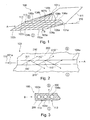
- Fig. 1 shows a perspective view of a Ionendosiervoriques without separator according to an exemplary embodiment of the present invention.
- Fig. 1 a plurality of power-conducting devices.
- the energy-directing device 102a, 103a, 104a, 105a, 106a, 102b, 103b, 104b, 105b, 106b, 107b, 108b, 109b of the ion-metering device 100 is designed as a network of at least one first energy-directing device 102a, 103a, 104a, 105a, 106a and at least a second power-conducting device 102b, 103b, 104b, 105b, 106b, 107b, 108b, 109b.
- the ion metering device 100 may, however, also have only a single first energy-conducting device 104a, which has an in Fig. 1 Sheathing device, not shown, is sheathed.
- optical fibers, optical fibers or fibers will be used as the first energy directing means 102a, 103a, 104a, 105a, 106a or as second energy-conducting device 102b, 103b, 104b, 105b, 106b, 107b, 108b, 109b, which form a network of energy-conducting devices for the ion-metering device 100.
- the first energy-conducting device 102a, 103a, 104a, 105a, 106a and the second energy-conducting device 102b, 103b, 104b, 105b, 106b, 107b, 108b, 109b are separated from one another and arranged at right angles to one another. This results in the rectangular openings 113, the rectangular meshes 113 or the grid openings 113 in the energy-conducting devices or in the ion-metering device 100.
- the first energy-conducting device 102a, 103a, 104a, 105a, 106a and the second energy-conducting device 102b, 103b, 104b, 105b, 106b , 107b, 108b, 109b are powered by the same energy source.
- the optical source described is the laser radiation 110, which transports an optical energy.
- different power control devices can also be powered from different energy sources. This may be the case, for example, when different properties are to be set in the separator by means of energy sources.
- the first energy 110 is transferred via the first energy supply device 101 a and via the second energy supply device 101 b into the first energy-conducting device 102a, 103a, 104a, 105a, 106a or into the second energy-conducting device 102b, 103b, 104b, 105b, 106b, 107b, 108b , 109b coupled.
- the first energy supply device 101a and the second energy supply device 101b are designed as beam splitters 101a, 101b, each of the plurality of first energy control devices 102a, 103a, 104a, 105a, 106a and the plurality of second energy control devices 102b, 103b, 104b, 105b, 106b, 107b, 108b, 109b of the ion meter 100 energized.
- the first energy supply device 101a also decouples the energy for the second energy-conducting device 102b, 103b, 104b, 105b, 106b, 107b, 108b, 109b from the first energy supply device 101a via the stub 111.
- the first energy-conducting device 102a, 103a, 104a, 105a, 106a and for the second energy-conducting device 102b, 103b, 104b, 105b, 106b, 107b, 108b, 109b different forms of energy, such as optical energy and thermal energy, are used, if provided for the first energy-conducting device 102a, 103a, 104a, 105a, 106a and the second energy control device 102b, 103b, 104b, 105b, 106b, 107b, 108b, 109b
- corresponding physical energy control devices are, for example, optical conductors and thermal conductors.
- FIG Fig. 1 For better visibility of the energy-directing devices 102a, 103a, 104a, 105a, 106a, 102b, 103b, 104b, 105b, 106b, 107b, 108b, 109b of the ion-metering device 100 is shown in FIG Fig. 1 the disconnecting means are not shown, which are in the openings 113 of the power conductors of the ion metering device 100 and / or the plurality of first power-conducting devices 102a, 103a, 104a, 105a, 106a and the plurality of second power-conducting devices 102b, 103b, 104b, 105b, 106b 107b, 108b, 109b.
- the ion-metering device 100 may be present when the separation device is destroyed.
- the separator or barrier layer in the openings 113 may be formed as a polymer which closes the openings 113 and thus together with the first energy-conducting device 102a, 103a, 104a, 105a, 106a and / or with the second energy-conducting device 102b, 103b, 104b, 105b, 106b, 107b, 108b, 109b forms an ion metering device 100 or ion metering layer 100.
- the first energy-conducting device 102a, 103a, 104a, 105a, 106a and / or the second energy-conducting device 102b, 103b, 104b, 105b, 106b, 107b, 108b, 109b are thus embedded, for example, in a photochemically decomposable polymer.
- the separator is made of photochemically decomposable polymer, by bringing the laser radiation to the separator, the photochemically decomposable polymer can be destroyed.
- the combination of the first energy-conducting device 102a, 103a, 104a, 105a, 106a and second energy-conducting device 102b, 103b, 104b, 105b, 106b, 107b, 108b, 109b with the separating device can also be referred to as a switchable separator 100 and used for a battery.
- the switchable separator 100 can meter, limit, alter, or even substantially completely block an ion flow around the energy directing device.
- the switchable separator 100 or the ion metering device 100 is a device by means of which the storability of batteries can be increased. Examples of arrangements of the ion metering device 100 in a battery 400 are shown in FIG 4 and FIG. 5 shown.
- the separator 100, and particularly the separator of the ion meter 100, can reduce the self-discharge in a battery 400. Self-discharge is often caused by undesirable side reactions within the battery 400 or cell 400, which result in ion transport through the electrolyte 405 present in the battery 400.
- the electrolyte is provided in the battery 400 as an ion transport device 405.
- ion metering device 100 prevents ion transport caused by undesired side reactions within the battery 400 by inhibiting such ion transport in the electrolyte 405 during the period of storage of the battery.
- Another embodiment of the invention as an ion meter allows metering of the ion current within the cell, which can then be increased or decreased by increasing or decreasing the energy input. In particular, in fault cases, such a current control with regard to increased security can be made possible.
- the ion meter 100 may inhibit the ion transport process within the battery 400 through the electrolyte substantially for the duration of the battery storage.
- the ion transport barrier or separator is adjusted so that an ion transport through the Ionendosiervorides 100 and in particular through the separator therethrough corresponds to a predetermined size or is substantially unimpeded by the separator.
- the barrier effect of the separation device is destroyed, so that essentially through the openings 113 or through gaps 113 between the sections of the first energy-directing means an ion transport can take place, which is not disturbed by the Ionendosiervorraum 100.
- Fig. 2 shows a sectional view through a Ionendosiervorraum 100 according to an exemplary embodiment of the present invention.
- the Fig. 2 shows the section through the first energy control device 104a of Fig. 1 , Which surrounded by the separator 200.
- the ion separator 200 is a photochemically decomposable polymer as far as the supply of radiation as an energy form is concerned.
- the first energy-conducting device 104a or the optical fiber 104a is completely surrounded by the separating device 200, in particular by the barrier layer material 200.
- the separator 200 blocked in the present case the Fig.
- the sectional view of the Fig. 2 corresponds to a section along the cutting mark A of Fig. 1 ,
- the first energy 110 is coupled into the first energy-conducting device 104a from the side of the first energy supply device 101a.
- the first energy is a laser radiation 110 and thus an optical energy 110.
- the optical energy 110 is guided along the first energy-conducting device 104a in the interior of the energy-conducting device 104a by reflections at the boundary layer 201, so that the laser radiation 110 inside the energy-conducting device 104 as rays 110 ', 110 ", 110'” propagates.
- the loss energy in the form of radiation 210 ', 210 ", 210'" is coupled out of the first energy-directing device 104a into the separator 200 or barrier layer 200.
- a structure may be incorporated in an optical waveguide, for example a structure in a gradient fiber, such as microprisms or microcavels with a variable period.
- the angle of incidence of the radiation can decrease to such an extent that it becomes smaller than the critical angle for the total reflection.
- a decoupling of radiation can be achieved.
- the decoupled energy 210 ', 210 ", 210" can interact with the separator 200 or the photochemically decomposable polymer 200, thereby destroying the separator 200 or ionic conductivity the separator 200 is affected.
- the high energy output can be achieved by a physical adaptation of a waveguide or a characteristic impedance in the lateral surface of the waveguide.
- the separator 200 forms, together with the first energy-conducting device 102a, 103a, 104a, 105a, 106a, a thin layer or a layer system which can be introduced between both electrodes of a battery in addition to an electrolyte 405 present in a battery 400.
- the electrolyte 405 may also include an additional separator and then forms an electrolyte separator system 405.
- This separator present in the electrolyte separator system is substantially responsible for the amount of ion flow when the barrier action of the separator 200 is removed.
- the separator of the electrolyte / separator system may have a low ionic conductivity as compared with the ionic conductivity of the separator 200.
- the release layer 200 is inert to the materials used in the battery 400, i. H. it does not lead to side reactions and the formation of reaction products which could limit the functionality of the battery.
- the separator 200 has the property of changing its ionic conductivity by an initial process so that the functionality of the battery can be established within a short time. In this case, the interruption of the ion transport paths caused by the separation device 200 is destroyed by the initial process, so that the functionality of the battery can be produced within a short time.
- the initial process or activation of the battery 400 causes the battery 400 to behave as if the ion meter 100 were absent. By a corresponding or else by another initial process, the barrier effect of the separator 200 can be restored.
- FIG. 12 shows a cross-sectional detail of the ion metering device 100 according to an exemplary embodiment of the present invention. It is a section of the cross section through the Ionendosiervorraum 100 along the cut mark B of Fig. 1 shown. Thus, the power supply 110 is in Fig. 3 not shown.
- the Fig. 3 FIG. 5 shows how the first energy-conducting device 102a, 103a, 104a is surrounded by the separating device 200, for example the polymer 200, and forms the ion-metering device 100.
- the intermediate spaces 113 between the first energy-conducting devices 102a, 103a, 104a are thereby closed by the separating device 200, so that substantially no ion transport between the region I and the region II along the symbolically illustrated arrow 300 or in the opposite direction is possible. Also, a transport past the energy-conducting device 102a, 103a, 104a, 105a, 106a, 102b, 103b, 104b, 105b, 106b, 107b, 108b, 109b or through the intermediate spaces 113 is blocked. Thus, separator 200 blocks ion transport between regions I and II and ion-dosing device 100. Separator 200 forms an ion transport barrier.
- the ion metering device 100 has a photochemically decomposable polymer layer 200 as a separator 200 or barrier layer 200.
- This polymer 200 is decomposed by introduction of energy, for example monochromatic radiation, for example by a laser, within a very short time or so damaged that the previously sealed ion transport paths 113 between the first energy control devices 102a, 103a, 104a are released. After the release of the transport paths 113 or the opening 113, an ion transport between the region I and the region II can take place.
- a discharge of the battery via an external circuit is possible and the battery 400 can be used. In this state, the battery 400 is activated.
- the resulting in the decomposition, remaining within the cell reaction products of photochemical decomposition should not adversely affect the battery behavior.
- a network of optical fibers 102a, 103a, 104a, 105a, 106a, 102b, 103b, 104b, 105b, 106b, 107b, 108b, 109b is introduced into the layer 100 brought in.
- the fibers 102a, 103a, 104a, 105a, 106a, 102b, 103b, 104b, 105b, 106b, 107b, 108b, 109b used have high losses with respect to radiation transport, i. H.
- a significant portion of the radiation 110 ', 110 ", 110'” is coupled into the polymer 200 through the fiber walls 201 during the reflective processes on the fiber walls 201, or may allow the optical fiber, e.g. by an introduced structure the defined coupling of a part of the radiation.
- the decoupled energy interacts with the polymer 200 and initiates in the polymer 200 the desired photochemical reaction, for example the decomposition of the polymer 200 or the surrounding separator 200.
- the separator or battery 400 is enabled so that ion transport is enabled and the battery operates substantially unrestricted.
- the ion metering device 100 that is, the system polymer optical fiber 100, be selected so that, depending on the wavelength of the radiation used 110, the properties of the embedding material, ie the material of the barrier layer 200, change so that the Barrier layer 200, that is, substantially the surrounding material 200, is opened for the ion transport process.
- the barrier layer 100 can be restored, so that the openings 113 by the recovery of the Embedding material 200 to be closed again.
- the battery function can be switched on or switched off or even dosed.
- optical fibers 102a, 103a, 104a, 105a, 106a, 102b, 103b, 104b, 105b, 106b, 107b, 108b, 109b is also a thermal or electrical destruction or destruction of the barrier layer 100 and in particular the separator 200 conceivable.
- the first energy-directing device 102a, 103a, 104a, 105a, 106a is an optical energy-directing device for transporting an optical energy
- the second energy-directing device 102b, 103b, 104b, 105b, 106b, 107b, 108b, 109b is designed for thermal energy transport, for example by means of heating wires 102b, 103b, 104b, 105b, 106b, 107b, 108b, 109b.
- a barrier layer 200 and in particular the separator 200 could be opened or destroyed by supplying optical energy via the first energy-directing device 102a, 103a, 104a, 105a, 106a and then later by supplying the second energy via the second energy-directing device 102b, 103b, 104b , 105b, 106b, 107b, 108b, 109b or via an additional embedded network by means of thermal influencing of the material 200 and the separator 200 are closed again and thus the barrier effect can be restored.
- the Fig. 4 shows a first energy storage device according to an exemplary embodiment of the present invention.
- the energy storage device 400, the battery 400 or the accumulator 400 has a first electrode 401 or anode 401 and a second electrode 402 or cathode 402.
- a first active material 403 is arranged and at the second electrode, a second active material 404 is arranged.
- the active materials 403, 404 serve to release ions and generate electrical charges during the electrochemical reactions taking place in the active material.
- the Electric charges can be dissipated via the electrode terminals 406, 407 or current conductors 406, 407.
- the energy storage device 400 has three terminals, namely, the electrode terminals 407, 407 for dissipating the energy stored in the energy storage device 400 and the activation terminal 101a or the power supply 101a for activating the energy storage device 400. Only after the activation can be stored at the electrode terminals 406, 407 Energy to be dissipated.
- the battery is switched on or switched on by means of the ion metering device 100.
- an electrical circuit in an outer region of the battery 400 can be produced, which is powered by the battery 400. Ion transport within the battery 400 is provided by the electrolyte 405.
- the electrolyte 405 may also include a separator which is responsible for the size of the ion flux and forms an electrolyte / separator system 405 with the electrolyte.
- the separator 200 is inserted into the electrolyte 405, which separates the two regions I and II within the battery by the existing separator 200 from each other and prevents ion flow.
- Fig. 4 a battery in a storable state, which allows a long-term storage.
- the separator 200 or barrier device 200 as part of the Ionendosiervortechnisch 100 prevents the exchange of ions.
- Fig. 5 shows an alternative layer structure of a battery 400, in which the Ionendosiervoriques 100 is arranged with the separator 200 between the electrolyte 405 and the first active material 403. Even with this alternative positioning of the barrier layer 100, the barrier layer 100 substantially completely prevents ion transport between the two regions I and II. Alternatively, the ion dosage device 100 present in the barrier layer 100 can be set up such that the ion transport is not completely prevented is controlled only by the amount of energy provided.
Landscapes
- Chemical & Material Sciences (AREA)
- Chemical Kinetics & Catalysis (AREA)
- Electrochemistry (AREA)
- General Chemical & Material Sciences (AREA)
- Engineering & Computer Science (AREA)
- Physics & Mathematics (AREA)
- Manufacturing & Machinery (AREA)
- Spectroscopy & Molecular Physics (AREA)
- General Engineering & Computer Science (AREA)
- High Energy & Nuclear Physics (AREA)
- Secondary Cells (AREA)
- Cell Separators (AREA)
Applications Claiming Priority (1)
| Application Number | Priority Date | Filing Date | Title |
|---|---|---|---|
| DE102013013295.9A DE102013013295A1 (de) | 2013-08-12 | 2013-08-12 | Ionendosiervorrichtung für eine Energiespeichervorrichtung, Verfahren zum Herstellen einer Ionendosiervorrichtung und Energiespeichervorrichtung |
Publications (2)
| Publication Number | Publication Date |
|---|---|
| EP2838136A1 true EP2838136A1 (fr) | 2015-02-18 |
| EP2838136B1 EP2838136B1 (fr) | 2018-03-21 |
Family
ID=51355401
Family Applications (1)
| Application Number | Title | Priority Date | Filing Date |
|---|---|---|---|
| EP14002682.4A Not-in-force EP2838136B1 (fr) | 2013-08-12 | 2014-07-31 | Dispositif de dosage d'ions pour un dispositif de stockage d'énergie, procédé de fabrication d'un dispositif de dosage d'ions et dispositif de stockage d'énergie |
Country Status (3)
| Country | Link |
|---|---|
| US (1) | US9129719B2 (fr) |
| EP (1) | EP2838136B1 (fr) |
| DE (1) | DE102013013295A1 (fr) |
Families Citing this family (4)
| Publication number | Priority date | Publication date | Assignee | Title |
|---|---|---|---|---|
| CA3202806A1 (fr) | 2020-12-29 | 2022-07-07 | Maisam DADGAR | Puce microfluidique a haut debit presentant des etranglements parallelises pour perturber des membranes cellulaires |
| DE102021212076B4 (de) | 2021-10-26 | 2024-01-25 | Volkswagen Aktiengesellschaft | Batteriezelle |
| CN115249872A (zh) * | 2022-06-28 | 2022-10-28 | 电子科技大学 | 一种离子传导介质、电容储能器件及其应用 |
| DE102024203071A1 (de) * | 2024-04-03 | 2025-10-09 | Volkswagen Aktiengesellschaft | Batteriezelle mit Heizdraht, Batteriesystem und Kraftfahrzeug |
Citations (6)
| Publication number | Priority date | Publication date | Assignee | Title |
|---|---|---|---|---|
| GB191123265A (en) * | 1911-10-21 | 1912-03-07 | Pascal Marino | Improvements in the Manufacture of Electrical Accumulators. |
| EP0291459A2 (fr) | 1987-05-15 | 1988-11-17 | Ciba-Geigy Ag | Procédé pour le travail ablatif des corps optiques à base de polymères réticulés |
| WO1990002327A1 (fr) | 1988-08-18 | 1990-03-08 | AUSTRALIAN MEMBRANE AND BIOTECHNOLOGY RESEARCH INSTITUTE LTD., Commonwealth Scientific and Industrial Research Organization | Ameliorations apportees a la sensibilite et a la selectivite de biocapteurs avec membranes a canaux ioniques |
| US6326105B1 (en) * | 1998-06-12 | 2001-12-04 | Lithium Technology Corporation | Composite polymer electrolytes for alkali metal electrochemical devices which contain a non-woven glass fiber net |
| US20050201715A1 (en) * | 2004-03-29 | 2005-09-15 | Panorama Flat Ltd. | System, method, and computer program product for magneto-optic device display |
| US20120237816A1 (en) * | 2011-03-15 | 2012-09-20 | YottaQ, Inc. | Low-cost high-power battery and enabling bipolar substrate |
Family Cites Families (7)
| Publication number | Priority date | Publication date | Assignee | Title |
|---|---|---|---|---|
| GB23265A (fr) | 1911-10-21 | |||
| US4898602A (en) * | 1988-03-28 | 1990-02-06 | Gruber Thomas J | Selectively openable filtering assembly |
| DE19811708B4 (de) * | 1997-09-20 | 2008-09-04 | Evonik Degussa Gmbh | Herstellung von keramischen Membranen |
| JP3891069B2 (ja) * | 2002-08-09 | 2007-03-07 | トヨタ自動車株式会社 | 燃料電池のセパレータ |
| DE10347567A1 (de) * | 2003-10-14 | 2005-05-12 | Degussa | Elektrischer Separator mit Abschaltmechanismus, Verfahren zu dessen Herstellung und Verwendung in Lithium-Batterien |
| WO2012047291A1 (fr) * | 2010-10-06 | 2012-04-12 | The Enser Corporation | Batterie thermique pour systèmes électriques |
| US9406971B2 (en) | 2011-07-01 | 2016-08-02 | GM Global Technology Operations LLC | Shape memory polymer containing composite materials |
-
2013
- 2013-08-12 DE DE102013013295.9A patent/DE102013013295A1/de not_active Withdrawn
-
2014
- 2014-07-31 EP EP14002682.4A patent/EP2838136B1/fr not_active Not-in-force
- 2014-08-11 US US14/456,584 patent/US9129719B2/en active Active
Patent Citations (6)
| Publication number | Priority date | Publication date | Assignee | Title |
|---|---|---|---|---|
| GB191123265A (en) * | 1911-10-21 | 1912-03-07 | Pascal Marino | Improvements in the Manufacture of Electrical Accumulators. |
| EP0291459A2 (fr) | 1987-05-15 | 1988-11-17 | Ciba-Geigy Ag | Procédé pour le travail ablatif des corps optiques à base de polymères réticulés |
| WO1990002327A1 (fr) | 1988-08-18 | 1990-03-08 | AUSTRALIAN MEMBRANE AND BIOTECHNOLOGY RESEARCH INSTITUTE LTD., Commonwealth Scientific and Industrial Research Organization | Ameliorations apportees a la sensibilite et a la selectivite de biocapteurs avec membranes a canaux ioniques |
| US6326105B1 (en) * | 1998-06-12 | 2001-12-04 | Lithium Technology Corporation | Composite polymer electrolytes for alkali metal electrochemical devices which contain a non-woven glass fiber net |
| US20050201715A1 (en) * | 2004-03-29 | 2005-09-15 | Panorama Flat Ltd. | System, method, and computer program product for magneto-optic device display |
| US20120237816A1 (en) * | 2011-03-15 | 2012-09-20 | YottaQ, Inc. | Low-cost high-power battery and enabling bipolar substrate |
Also Published As
| Publication number | Publication date |
|---|---|
| EP2838136B1 (fr) | 2018-03-21 |
| US9129719B2 (en) | 2015-09-08 |
| DE102013013295A1 (de) | 2015-02-12 |
| US20150060689A1 (en) | 2015-03-05 |
Similar Documents
| Publication | Publication Date | Title |
|---|---|---|
| EP2838136B1 (fr) | Dispositif de dosage d'ions pour un dispositif de stockage d'énergie, procédé de fabrication d'un dispositif de dosage d'ions et dispositif de stockage d'énergie | |
| DE202018006912U1 (de) | Sekundärbatterie und Herstellung | |
| EP2647070A1 (fr) | Procédé et système pour découper des objets en forme de feuilles ou de plaques | |
| DE112011100279T5 (de) | Batteriezellen- Modul für eine modulare Batterie mit einem verschachtelt angeordnetem Trennelement | |
| EP2603947A1 (fr) | Enveloppe pour une pile électrochimique | |
| WO2011012198A1 (fr) | Batterie comprenant une pluralité d'éléments de batterie en forme de plaques | |
| WO2013092898A1 (fr) | Batterie à circulation d'oxydo-réduction avec ligne d'alimentation et/ou ligne d'évacuation externes | |
| EP3284119B1 (fr) | Batterie comprenant un boîtier métallique prismatique | |
| DE102017218130A1 (de) | Verfahren zur Herstellung eines Stromableiters, Elektrode und Batteriezelle | |
| DE102022106393A1 (de) | Batteriezelle sowie Verfahren zur Herstellung einer solchen Batteriezelle | |
| EP3143652A2 (fr) | Unité batterie comprenant une pluralité de cellules électrochimiques et module de batterie comprenant une pluralité d'unités batterie | |
| EP2764561A1 (fr) | Procédé et système pour découper des objets en forme de feuille ou de plaque | |
| DE1214783B (fr) | ||
| WO2019141764A1 (fr) | Dispositif de test d'une cellule électrochimique, module muni d'un dispositif de test, et procédé permettant de tester une cellule électrochimique | |
| EP0966768B1 (fr) | Systeme de batterie rechargeable et utilisation | |
| DE102010053341A1 (de) | Verfahren und System zum Schneiden von blatt- oder plattenförmigen Objekten | |
| DE102012006642A1 (de) | Durchflussbatterie, elektrochemischer Energiewandler für eine Durchflussbatterie, Zellrahmen und Bipolarplatte sowie Kollektorplatte | |
| DE102014209978B4 (de) | Speicherelement für Elektroenergie und Verfahren zur Herstellung eines Speicherelements | |
| EP3982455B1 (fr) | Élément de batterie destinée à la mise en oeuvre d'un essai de sécurité | |
| DE102018212448A1 (de) | Festkörperelektrolyt-Batteriezelle mit in eine Elektrolytschicht eingelagerter Sensorlage | |
| DE102022003450B3 (de) | Gehäuse für eine Batterieeinzelzelle | |
| DE102021212076B4 (de) | Batteriezelle | |
| DE102021118693B4 (de) | Ladungsträger-Trennvorrichtung und Verfahren zum Erzeugen einer elektrischen Spannung und/oder eines elektrischen Stroms | |
| DE102023122417A1 (de) | Test-Batteriezelle, Test-Batteriemodul, Test-Batterieanordnung und Verfahren zum gezielten Auslösen eines thermischen Durchgehens einer Test-Batteriezelle | |
| EP3982456A1 (fr) | Élément de batterie destinée à la mise en oeuvre d'un essai de sécurité |
Legal Events
| Date | Code | Title | Description |
|---|---|---|---|
| 17P | Request for examination filed |
Effective date: 20140731 |
|
| AK | Designated contracting states |
Kind code of ref document: A1 Designated state(s): AL AT BE BG CH CY CZ DE DK EE ES FI FR GB GR HR HU IE IS IT LI LT LU LV MC MK MT NL NO PL PT RO RS SE SI SK SM TR |
|
| AX | Request for extension of the european patent |
Extension state: BA ME |
|
| PUAI | Public reference made under article 153(3) epc to a published international application that has entered the european phase |
Free format text: ORIGINAL CODE: 0009012 |
|
| R17P | Request for examination filed (corrected) |
Effective date: 20150629 |
|
| RBV | Designated contracting states (corrected) |
Designated state(s): AL AT BE BG CH CY CZ DE DK EE ES FI FR GB GR HR HU IE IS IT LI LT LU LV MC MK MT NL NO PL PT RO RS SE SI SK SM TR |
|
| 17Q | First examination report despatched |
Effective date: 20160203 |
|
| GRAP | Despatch of communication of intention to grant a patent |
Free format text: ORIGINAL CODE: EPIDOSNIGR1 |
|
| STAA | Information on the status of an ep patent application or granted ep patent |
Free format text: STATUS: GRANT OF PATENT IS INTENDED |
|
| INTG | Intention to grant announced |
Effective date: 20170929 |
|
| GRAS | Grant fee paid |
Free format text: ORIGINAL CODE: EPIDOSNIGR3 |
|
| GRAA | (expected) grant |
Free format text: ORIGINAL CODE: 0009210 |
|
| STAA | Information on the status of an ep patent application or granted ep patent |
Free format text: STATUS: THE PATENT HAS BEEN GRANTED |
|
| AK | Designated contracting states |
Kind code of ref document: B1 Designated state(s): AL AT BE BG CH CY CZ DE DK EE ES FI FR GB GR HR HU IE IS IT LI LT LU LV MC MK MT NL NO PL PT RO RS SE SI SK SM TR |
|
| REG | Reference to a national code |
Ref country code: GB Ref legal event code: FG4D Free format text: NOT ENGLISH |
|
| REG | Reference to a national code |
Ref country code: CH Ref legal event code: EP |
|
| REG | Reference to a national code |
Ref country code: AT Ref legal event code: REF Ref document number: 981992 Country of ref document: AT Kind code of ref document: T Effective date: 20180415 |
|
| REG | Reference to a national code |
Ref country code: IE Ref legal event code: FG4D Free format text: LANGUAGE OF EP DOCUMENT: GERMAN |
|
| REG | Reference to a national code |
Ref country code: DE Ref legal event code: R096 Ref document number: 502014007658 Country of ref document: DE |
|
| REG | Reference to a national code |
Ref country code: NL Ref legal event code: MP Effective date: 20180321 |
|
| REG | Reference to a national code |
Ref country code: FR Ref legal event code: PLFP Year of fee payment: 5 |
|
| PG25 | Lapsed in a contracting state [announced via postgrant information from national office to epo] |
Ref country code: LT Free format text: LAPSE BECAUSE OF FAILURE TO SUBMIT A TRANSLATION OF THE DESCRIPTION OR TO PAY THE FEE WITHIN THE PRESCRIBED TIME-LIMIT Effective date: 20180321 Ref country code: HR Free format text: LAPSE BECAUSE OF FAILURE TO SUBMIT A TRANSLATION OF THE DESCRIPTION OR TO PAY THE FEE WITHIN THE PRESCRIBED TIME-LIMIT Effective date: 20180321 Ref country code: CY Free format text: LAPSE BECAUSE OF FAILURE TO SUBMIT A TRANSLATION OF THE DESCRIPTION OR TO PAY THE FEE WITHIN THE PRESCRIBED TIME-LIMIT Effective date: 20180321 Ref country code: NO Free format text: LAPSE BECAUSE OF FAILURE TO SUBMIT A TRANSLATION OF THE DESCRIPTION OR TO PAY THE FEE WITHIN THE PRESCRIBED TIME-LIMIT Effective date: 20180621 Ref country code: FI Free format text: LAPSE BECAUSE OF FAILURE TO SUBMIT A TRANSLATION OF THE DESCRIPTION OR TO PAY THE FEE WITHIN THE PRESCRIBED TIME-LIMIT Effective date: 20180321 |
|
| REG | Reference to a national code |
Ref country code: LT Ref legal event code: MG4D |
|
| PG25 | Lapsed in a contracting state [announced via postgrant information from national office to epo] |
Ref country code: GR Free format text: LAPSE BECAUSE OF FAILURE TO SUBMIT A TRANSLATION OF THE DESCRIPTION OR TO PAY THE FEE WITHIN THE PRESCRIBED TIME-LIMIT Effective date: 20180622 Ref country code: SE Free format text: LAPSE BECAUSE OF FAILURE TO SUBMIT A TRANSLATION OF THE DESCRIPTION OR TO PAY THE FEE WITHIN THE PRESCRIBED TIME-LIMIT Effective date: 20180321 Ref country code: LV Free format text: LAPSE BECAUSE OF FAILURE TO SUBMIT A TRANSLATION OF THE DESCRIPTION OR TO PAY THE FEE WITHIN THE PRESCRIBED TIME-LIMIT Effective date: 20180321 Ref country code: BG Free format text: LAPSE BECAUSE OF FAILURE TO SUBMIT A TRANSLATION OF THE DESCRIPTION OR TO PAY THE FEE WITHIN THE PRESCRIBED TIME-LIMIT Effective date: 20180621 Ref country code: RS Free format text: LAPSE BECAUSE OF FAILURE TO SUBMIT A TRANSLATION OF THE DESCRIPTION OR TO PAY THE FEE WITHIN THE PRESCRIBED TIME-LIMIT Effective date: 20180321 |
|
| PG25 | Lapsed in a contracting state [announced via postgrant information from national office to epo] |
Ref country code: MT Free format text: LAPSE BECAUSE OF FAILURE TO SUBMIT A TRANSLATION OF THE DESCRIPTION OR TO PAY THE FEE WITHIN THE PRESCRIBED TIME-LIMIT Effective date: 20180321 |
|
| PG25 | Lapsed in a contracting state [announced via postgrant information from national office to epo] |
Ref country code: IT Free format text: LAPSE BECAUSE OF FAILURE TO SUBMIT A TRANSLATION OF THE DESCRIPTION OR TO PAY THE FEE WITHIN THE PRESCRIBED TIME-LIMIT Effective date: 20180321 Ref country code: PL Free format text: LAPSE BECAUSE OF FAILURE TO SUBMIT A TRANSLATION OF THE DESCRIPTION OR TO PAY THE FEE WITHIN THE PRESCRIBED TIME-LIMIT Effective date: 20180321 Ref country code: AL Free format text: LAPSE BECAUSE OF FAILURE TO SUBMIT A TRANSLATION OF THE DESCRIPTION OR TO PAY THE FEE WITHIN THE PRESCRIBED TIME-LIMIT Effective date: 20180321 Ref country code: ES Free format text: LAPSE BECAUSE OF FAILURE TO SUBMIT A TRANSLATION OF THE DESCRIPTION OR TO PAY THE FEE WITHIN THE PRESCRIBED TIME-LIMIT Effective date: 20180321 Ref country code: EE Free format text: LAPSE BECAUSE OF FAILURE TO SUBMIT A TRANSLATION OF THE DESCRIPTION OR TO PAY THE FEE WITHIN THE PRESCRIBED TIME-LIMIT Effective date: 20180321 Ref country code: NL Free format text: LAPSE BECAUSE OF FAILURE TO SUBMIT A TRANSLATION OF THE DESCRIPTION OR TO PAY THE FEE WITHIN THE PRESCRIBED TIME-LIMIT Effective date: 20180321 Ref country code: RO Free format text: LAPSE BECAUSE OF FAILURE TO SUBMIT A TRANSLATION OF THE DESCRIPTION OR TO PAY THE FEE WITHIN THE PRESCRIBED TIME-LIMIT Effective date: 20180321 |
|
| PG25 | Lapsed in a contracting state [announced via postgrant information from national office to epo] |
Ref country code: SM Free format text: LAPSE BECAUSE OF FAILURE TO SUBMIT A TRANSLATION OF THE DESCRIPTION OR TO PAY THE FEE WITHIN THE PRESCRIBED TIME-LIMIT Effective date: 20180321 Ref country code: CZ Free format text: LAPSE BECAUSE OF FAILURE TO SUBMIT A TRANSLATION OF THE DESCRIPTION OR TO PAY THE FEE WITHIN THE PRESCRIBED TIME-LIMIT Effective date: 20180321 Ref country code: SK Free format text: LAPSE BECAUSE OF FAILURE TO SUBMIT A TRANSLATION OF THE DESCRIPTION OR TO PAY THE FEE WITHIN THE PRESCRIBED TIME-LIMIT Effective date: 20180321 |
|
| PG25 | Lapsed in a contracting state [announced via postgrant information from national office to epo] |
Ref country code: PT Free format text: LAPSE BECAUSE OF FAILURE TO SUBMIT A TRANSLATION OF THE DESCRIPTION OR TO PAY THE FEE WITHIN THE PRESCRIBED TIME-LIMIT Effective date: 20180723 |
|
| REG | Reference to a national code |
Ref country code: DE Ref legal event code: R097 Ref document number: 502014007658 Country of ref document: DE |
|
| PLBE | No opposition filed within time limit |
Free format text: ORIGINAL CODE: 0009261 |
|
| STAA | Information on the status of an ep patent application or granted ep patent |
Free format text: STATUS: NO OPPOSITION FILED WITHIN TIME LIMIT |
|
| PG25 | Lapsed in a contracting state [announced via postgrant information from national office to epo] |
Ref country code: DK Free format text: LAPSE BECAUSE OF FAILURE TO SUBMIT A TRANSLATION OF THE DESCRIPTION OR TO PAY THE FEE WITHIN THE PRESCRIBED TIME-LIMIT Effective date: 20180321 |
|
| 26N | No opposition filed |
Effective date: 20190102 |
|
| REG | Reference to a national code |
Ref country code: CH Ref legal event code: PL |
|
| PG25 | Lapsed in a contracting state [announced via postgrant information from national office to epo] |
Ref country code: MC Free format text: LAPSE BECAUSE OF FAILURE TO SUBMIT A TRANSLATION OF THE DESCRIPTION OR TO PAY THE FEE WITHIN THE PRESCRIBED TIME-LIMIT Effective date: 20180321 Ref country code: LU Free format text: LAPSE BECAUSE OF NON-PAYMENT OF DUE FEES Effective date: 20180731 |
|
| REG | Reference to a national code |
Ref country code: BE Ref legal event code: MM Effective date: 20180731 |
|
| PG25 | Lapsed in a contracting state [announced via postgrant information from national office to epo] |
Ref country code: LI Free format text: LAPSE BECAUSE OF NON-PAYMENT OF DUE FEES Effective date: 20180731 Ref country code: CH Free format text: LAPSE BECAUSE OF NON-PAYMENT OF DUE FEES Effective date: 20180731 |
|
| REG | Reference to a national code |
Ref country code: IE Ref legal event code: MM4A |
|
| PG25 | Lapsed in a contracting state [announced via postgrant information from national office to epo] |
Ref country code: BE Free format text: LAPSE BECAUSE OF NON-PAYMENT OF DUE FEES Effective date: 20180731 Ref country code: SI Free format text: LAPSE BECAUSE OF FAILURE TO SUBMIT A TRANSLATION OF THE DESCRIPTION OR TO PAY THE FEE WITHIN THE PRESCRIBED TIME-LIMIT Effective date: 20180321 |
|
| PG25 | Lapsed in a contracting state [announced via postgrant information from national office to epo] |
Ref country code: IE Free format text: LAPSE BECAUSE OF NON-PAYMENT OF DUE FEES Effective date: 20180731 |
|
| PG25 | Lapsed in a contracting state [announced via postgrant information from national office to epo] |
Ref country code: TR Free format text: LAPSE BECAUSE OF FAILURE TO SUBMIT A TRANSLATION OF THE DESCRIPTION OR TO PAY THE FEE WITHIN THE PRESCRIBED TIME-LIMIT Effective date: 20180321 |
|
| PG25 | Lapsed in a contracting state [announced via postgrant information from national office to epo] |
Ref country code: HU Free format text: LAPSE BECAUSE OF FAILURE TO SUBMIT A TRANSLATION OF THE DESCRIPTION OR TO PAY THE FEE WITHIN THE PRESCRIBED TIME-LIMIT; INVALID AB INITIO Effective date: 20140731 |
|
| PG25 | Lapsed in a contracting state [announced via postgrant information from national office to epo] |
Ref country code: MK Free format text: LAPSE BECAUSE OF NON-PAYMENT OF DUE FEES Effective date: 20180321 |
|
| PG25 | Lapsed in a contracting state [announced via postgrant information from national office to epo] |
Ref country code: IS Free format text: LAPSE BECAUSE OF FAILURE TO SUBMIT A TRANSLATION OF THE DESCRIPTION OR TO PAY THE FEE WITHIN THE PRESCRIBED TIME-LIMIT Effective date: 20180721 |
|
| REG | Reference to a national code |
Ref country code: AT Ref legal event code: MM01 Ref document number: 981992 Country of ref document: AT Kind code of ref document: T Effective date: 20190731 |
|
| REG | Reference to a national code |
Ref country code: DE Ref legal event code: R079 Ref document number: 502014007658 Country of ref document: DE Free format text: PREVIOUS MAIN CLASS: H01M0002140000 Ipc: H01M0050400000 |
|
| PG25 | Lapsed in a contracting state [announced via postgrant information from national office to epo] |
Ref country code: AT Free format text: LAPSE BECAUSE OF NON-PAYMENT OF DUE FEES Effective date: 20190731 |
|
| PGFP | Annual fee paid to national office [announced via postgrant information from national office to epo] |
Ref country code: GB Payment date: 20230720 Year of fee payment: 10 |
|
| PGFP | Annual fee paid to national office [announced via postgrant information from national office to epo] |
Ref country code: FR Payment date: 20230725 Year of fee payment: 10 Ref country code: DE Payment date: 20230719 Year of fee payment: 10 |
|
| REG | Reference to a national code |
Ref country code: DE Ref legal event code: R119 Ref document number: 502014007658 Country of ref document: DE |
|
| GBPC | Gb: european patent ceased through non-payment of renewal fee |
Effective date: 20240731 |
|
| PG25 | Lapsed in a contracting state [announced via postgrant information from national office to epo] |
Ref country code: DE Free format text: LAPSE BECAUSE OF NON-PAYMENT OF DUE FEES Effective date: 20250201 |
|
| PG25 | Lapsed in a contracting state [announced via postgrant information from national office to epo] |
Ref country code: FR Free format text: LAPSE BECAUSE OF NON-PAYMENT OF DUE FEES Effective date: 20240731 |
|
| PG25 | Lapsed in a contracting state [announced via postgrant information from national office to epo] |
Ref country code: GB Free format text: LAPSE BECAUSE OF NON-PAYMENT OF DUE FEES Effective date: 20240731 |