EP2837465B1 - Apparatus and method for aero-contouring a surface of an aerodynamically functional coating - Google Patents
Apparatus and method for aero-contouring a surface of an aerodynamically functional coating Download PDFInfo
- Publication number
- EP2837465B1 EP2837465B1 EP14178493.4A EP14178493A EP2837465B1 EP 2837465 B1 EP2837465 B1 EP 2837465B1 EP 14178493 A EP14178493 A EP 14178493A EP 2837465 B1 EP2837465 B1 EP 2837465B1
- Authority
- EP
- European Patent Office
- Prior art keywords
- aero
- see
- contouring
- engagement force
- abrading
- Prior art date
- Legal status (The legal status is an assumption and is not a legal conclusion. Google has not performed a legal analysis and makes no representation as to the accuracy of the status listed.)
- Active
Links
- 238000000576 coating method Methods 0.000 title claims description 70
- 239000011248 coating agent Substances 0.000 title claims description 58
- 238000000034 method Methods 0.000 title claims description 58
- 239000000463 material Substances 0.000 claims description 27
- 238000004891 communication Methods 0.000 claims description 11
- 239000000356 contaminant Substances 0.000 claims description 7
- 238000012546 transfer Methods 0.000 claims description 6
- 238000013461 design Methods 0.000 description 17
- 239000003973 paint Substances 0.000 description 16
- 230000008878 coupling Effects 0.000 description 14
- 238000010168 coupling process Methods 0.000 description 14
- 238000005859 coupling reaction Methods 0.000 description 14
- 238000004519 manufacturing process Methods 0.000 description 14
- 238000010586 diagram Methods 0.000 description 9
- 239000003381 stabilizer Substances 0.000 description 8
- 238000005498 polishing Methods 0.000 description 6
- 230000008569 process Effects 0.000 description 6
- 239000012636 effector Substances 0.000 description 5
- 239000002245 particle Substances 0.000 description 5
- 230000008901 benefit Effects 0.000 description 4
- 239000006260 foam Substances 0.000 description 4
- 230000006870 function Effects 0.000 description 4
- 238000009499 grossing Methods 0.000 description 4
- 239000002002 slurry Substances 0.000 description 4
- 230000007547 defect Effects 0.000 description 3
- 230000004069 differentiation Effects 0.000 description 3
- DHKHKXVYLBGOIT-UHFFFAOYSA-N 1,1-Diethoxyethane Chemical compound CCOC(C)OCC DHKHKXVYLBGOIT-UHFFFAOYSA-N 0.000 description 2
- 229920004943 Delrin® Polymers 0.000 description 2
- 239000004677 Nylon Substances 0.000 description 2
- 239000011354 acetal resin Substances 0.000 description 2
- 239000000853 adhesive Substances 0.000 description 2
- 230000001070 adhesive effect Effects 0.000 description 2
- 239000000428 dust Substances 0.000 description 2
- 239000011521 glass Substances 0.000 description 2
- 230000010354 integration Effects 0.000 description 2
- 230000007774 longterm Effects 0.000 description 2
- 238000012423 maintenance Methods 0.000 description 2
- 229920001778 nylon Polymers 0.000 description 2
- 229920006324 polyoxymethylene Polymers 0.000 description 2
- 238000009987 spinning Methods 0.000 description 2
- 230000000007 visual effect Effects 0.000 description 2
- 235000015842 Hesperis Nutrition 0.000 description 1
- 235000012633 Iberis amara Nutrition 0.000 description 1
- 238000005299 abrasion Methods 0.000 description 1
- 230000004913 activation Effects 0.000 description 1
- 230000007613 environmental effect Effects 0.000 description 1
- 229920002457 flexible plastic Polymers 0.000 description 1
- 238000010438 heat treatment Methods 0.000 description 1
- 238000003780 insertion Methods 0.000 description 1
- 230000037431 insertion Effects 0.000 description 1
- 238000009434 installation Methods 0.000 description 1
- 238000003754 machining Methods 0.000 description 1
- 230000007246 mechanism Effects 0.000 description 1
- 230000004048 modification Effects 0.000 description 1
- 238000012986 modification Methods 0.000 description 1
- 230000008520 organization Effects 0.000 description 1
- 239000004033 plastic Substances 0.000 description 1
- 229920003023 plastic Polymers 0.000 description 1
- 230000009467 reduction Effects 0.000 description 1
- 238000009419 refurbishment Methods 0.000 description 1
- 230000008439 repair process Effects 0.000 description 1
- 230000003252 repetitive effect Effects 0.000 description 1
- 230000009466 transformation Effects 0.000 description 1
- 230000001131 transforming effect Effects 0.000 description 1
- 230000032258 transport Effects 0.000 description 1
- 125000000391 vinyl group Chemical group [H]C([*])=C([H])[H] 0.000 description 1
- 229920002554 vinyl polymer Polymers 0.000 description 1
Images


Classifications
-
- B—PERFORMING OPERATIONS; TRANSPORTING
- B24—GRINDING; POLISHING
- B24B—MACHINES, DEVICES, OR PROCESSES FOR GRINDING OR POLISHING; DRESSING OR CONDITIONING OF ABRADING SURFACES; FEEDING OF GRINDING, POLISHING, OR LAPPING AGENTS
- B24B23/00—Portable grinding machines, e.g. hand-guided; Accessories therefor
- B24B23/02—Portable grinding machines, e.g. hand-guided; Accessories therefor with rotating grinding tools; Accessories therefor
- B24B23/03—Portable grinding machines, e.g. hand-guided; Accessories therefor with rotating grinding tools; Accessories therefor the tool being driven in a combined movement
-
- B—PERFORMING OPERATIONS; TRANSPORTING
- B24—GRINDING; POLISHING
- B24B—MACHINES, DEVICES, OR PROCESSES FOR GRINDING OR POLISHING; DRESSING OR CONDITIONING OF ABRADING SURFACES; FEEDING OF GRINDING, POLISHING, OR LAPPING AGENTS
- B24B23/00—Portable grinding machines, e.g. hand-guided; Accessories therefor
- B24B23/005—Auxiliary devices used in connection with portable grinding machines, e.g. holders
-
- B—PERFORMING OPERATIONS; TRANSPORTING
- B24—GRINDING; POLISHING
- B24B—MACHINES, DEVICES, OR PROCESSES FOR GRINDING OR POLISHING; DRESSING OR CONDITIONING OF ABRADING SURFACES; FEEDING OF GRINDING, POLISHING, OR LAPPING AGENTS
- B24B55/00—Safety devices for grinding or polishing machines; Accessories fitted to grinding or polishing machines for keeping tools or parts of the machine in good working condition
- B24B55/06—Dust extraction equipment on grinding or polishing machines
- B24B55/10—Dust extraction equipment on grinding or polishing machines specially designed for portable grinding machines, e.g. hand-guided
- B24B55/102—Dust extraction equipment on grinding or polishing machines specially designed for portable grinding machines, e.g. hand-guided with rotating tools
Definitions
- the disclosure relates generally to devices, methods and systems for aero-contouring surfaces of structures and collecting abrading debris, and more specifically, to devices, methods and systems for aero-contouring surfaces of aerodynamically functional coatings applied to structures of air vehicles, such as aircraft, and collecting abrading debris.
- Air vehicles such as commercial passenger and cargo aircraft, may have exterior surfaces that are coated or painted with colorful and decorative designs.
- exterior surfaces of an air vehicle may include exterior surfaces of the tail, wings, fuselage, nacelles, or other exterior surfaces of the air vehicle.
- colorful and decorative designs may include airline livery designs which are standard paint schemes on aircraft that prominently display an airline's logo, name, or other identifying feature to provide branding and differentiation of the airline. Since airline livery designs may provide not only a decorative function, but also a branding and differentiation function, it is important that livery designs be consistently applied and with acceptable appearance, gloss, and long-term durability.
- EP 2596908 discloses a machine tool for machining surfaces provided with a dynamic balancing system.
- the disclosure refers to a machine tool comprising a motor with a motor shaft adapted for performing a rotational movement around an axis of rotation, a working element adapted for performing an orbital or rotating orbital or random orbital movement, means for transforming the rotational movement of the shaft into the orbital or rotating orbital or random orbital movement of the working element, the transformation means comprising an eccentric attachment and a counter weight, wherein the attachment and the counter weight are connected torque proof to the shaft.
- US 3284961 discloses a polishing device. This disclosure relates to a polishing device and more particularly to a portable device for polishing spots on metallic and other surfaces which are to be examined under the reflected light microscope.
- US 2009/117834 discloses a heatless slurry system for use with a glass removal apparatus for restoring a glass surface.
- the system comprises a slurry container and a pump mounted externally relative to the container to prevent heating of the slurry as the system is operated. Vacuum pressure is created by activation of the pump to promote circulation of the slurry within the tool, thereby allowing the latter to be worked against the surface.
- an aero-contouring apparatus in one embodiment of the disclosure, there is provided an aero-contouring apparatus according to claim1.
- the aero-contouring apparatus comprises a housing assembly.
- the aero-contouring apparatus further comprises a motor assembly disposed within the housing assembly.
- the motor assembly comprises a motor unit and a drive unit.
- the aero-contouring apparatus further comprises an engagement force/tilt limiting member coupled to the housing assembly.
- the engagement force/tilt limiting member has a central opening and has a bottom end configured to contact a surface to be aero-contoured of an aerodynamically functional coating applied to a structure.
- the aero-contouring apparatus further comprises an abrading unit coupled to the drive unit and inserted through the central opening in non-contact communication with the engagement force/tilt limiting member. The abrading unit is driven by the drive unit in a random orbit motion on the surface.
- the engagement force/tilt limiting member mechanically limits both an engagement force and any tilting motion of the abrading unit with respect to the surface.
- the aero-contouring apparatus may comprise a vacuum outlet port configured for attachment to a debris collection device.
- an aero-contouring system comprising a structure coated with an aerodynamically functional coating having a surface to be aero-contoured.
- the aero-contouring system further comprises an aero-contouring apparatus for aero-contouring the surface.
- the aero-contouring apparatus comprises a housing assembly and a motor assembly disposed within the housing assembly.
- the motor assembly comprises a motor unit and a drive unit.
- the aero-contouring system further comprises an engagement force/tilt limiting member coupled to the housing assembly.
- the engagement force/tilt limiting member has a central opening and has a bottom end configured to contact a surface to be aero-contoured of an aerodynamically functional coating applied to a structure.
- the aero-contouring system further comprises an abrading unit coupled to the drive unit and inserted through the central opening in non-contact communication with the engagement force/tilt limiting member.
- the abrading unit is driven by the drive unit in a random orbit motion on the surface.
- the engagement force/tilt limiting member mechanically limits both an engagement force and any tilting motion of the abrading unit with respect to the surface.
- the aero-contouring system may comprise a debris collection system for attachment to the aero-contouring apparatus further comprising a vacuum outlet port.
- a method for aero-contouring a surface of an aerodynamically functional coating applied to a structured comprises the step of contacting with an aero-contouring apparatus a surface to be aero-contoured of an aerodynamically functional coating applied to a structure.
- the aero-contouring apparatus comprises a housing assembly and a motor assembly disposed within the housing assembly.
- the motor assembly comprises a motor unit and a drive unit.
- the aero-contouring apparatus further comprises an engagement force/tilt limiting member coupled to the housing assembly.
- the engagement force/tilt limiting member has a central opening.
- the aero-contouring apparatus further comprises an abrading unit coupled to the drive unit and inserted through the central opening in non-contact communication with the engagement force/tilt limiting member.
- the aero-contouring apparatus may comprise a vacuum outlet port configured for attachment to a debris collection system.
- the method further comprises the step of moving the aero-contouring apparatus in a random orbit motion on the surface to abrade and smooth the surface.
- the method further comprises the step of mechanically limiting with the engagement force/tilt limiting member an engagement force and any tilting motion of the abrading unit with respect to the surface.
- the method further comprises the step of removing any surface inclusions and coating edges on the surface without resulting in excessive engagement force to the surface and without gouging the surface.
- an aero-contouring apparatus comprising: a housing assembly, a motor assembly disposed within the housing assembly, the motor assembly comprising a motor unit and a drive unit, an engagement force/tilt limiting member coupled to the housing assembly, the engagement force/tilt limiting member having a central opening and having a bottom end configured to contact a surface to be aero-contoured of an aerodynamically functional coating applied to a structure, and an abrading unit coupled to the drive unit and inserted through the central opening in non-contact communication with the engagement force/tilt limiting member, the abrading unit driven by the drive unit in a random orbit motion on the surface, the housing assembly, the motor assembly, the engagement force/tilt limiting member, and the abrading unit, together comprising an aero-contouring apparatus for aero-contouring the surface, wherein the engagement force/tilt limiting member mechanically limits both an engagement force and any tilting motion of the abrading unit with respect to the surface.
- the housing assembly may comprise a grip portion configured for manually holding the aero-contouring apparatus during manual operation.
- the housing assembly may comprise a vacuum outlet port configured for attachment to a debris collection system.
- the engagement force/tilt limiting member may comprise a converging nozzle portion and a diverging nozzle portion that together accelerate a suction driven air flow velocity at the surface to be aero-contoured to entrain abrading debris for collection in the debris collection system.
- the engagement force/tilt limiting member comprises a machined ring member having an outer rim portion with a non-squared edge configuration.
- the engagement force/tilt limiting member may be made of a material that prevents or minimizes transfer of any contaminant material or residue material from the engagement force/tilt limiting member to the surface to be aero-contoured.
- the aero-contouring apparatus may be configured for performing touch-up aero-contouring of the surface, and the housing assembly comprises one or more cut-out portions forming a viewing feature enabling an operator to view an aero-contouring location on the surface during touch-up aero-contouring with the aero-contouring apparatus.
- the abrading unit may comprise an abrading pad having a first side and a second side, a connector element attached to the first side and configured for connection to the drive unit, and an abrading media attached to the second side and configured for abrading the surface.
- the abrading unit may have an outer diameter with a length in a range of from about 1 inch (about 2.5cm) to less than about 3 inches (about 7.5cm).
- an aero-contouring system comprising: a structure coated with an aerodynamically functional coating, the aerodynamically functional coating having a surface to be aero-contoured, an aero-contouring apparatus for aero-contouring the surface, the aero-contouring apparatus comprising: a housing assembly, a motor assembly disposed within the housing assembly, the motor assembly comprising a motor unit and a drive unit, an engagement force/tilt limiting member coupled to the housing assembly, the engagement force/tilt limiting member having a central opening and having a bottom end configured to contact the surface of the aerodynamically functional coating, and an abrading unit coupled to the drive unit and inserted through the central opening in non-contact communication with the engagement force/tilt limiting member, the abrading unit driven by the drive unit in a random orbit motion on the surface, wherein the engagement force/tilt limiting member mechanically limits both an engagement force and any tilting motion of the abrading unit with respect to the surface.
- the system may further comprise a debris collection system configured for attachment to a vacuum outlet port coupled to the housing assembly.
- the engagement force/tilt limiting member may comprise a converging nozzle portion and a diverging nozzle portion that together accelerate a suction driven air flow velocity at the surface to be aero-contoured to entrain abrading debris for collection in the debris collection system.
- the structure may comprise one or more of a tail of an air vehicle, including a vertical stabilizer tail portion and horizontal stabilizer tail portions; wings of an air vehicle, including winglets; fuselage of an air vehicle; and nacelles of an air vehicle.
- the aerodynamically functional coating may comprise an aerodynamically functional film element.
- the aero-contouring apparatus may be configured for performing touch-up aero-contouring of the surface, and the housing assembly comprises one or more cut-out portions forming a viewing feature enabling an operator to view an aero-contouring location on the surface during touch-up aero-contouring with the aero-contouring apparatus.
- a method for aero-contouring a surface of an aerodynamically functional coating applied to a structure comprising the steps of: contacting with an aero-contouring apparatus a surface to be aero-contoured of an aerodynamically functional coating applied to a structure, the aero-contouring apparatus comprising: a housing assembly, a motor assembly disposed within the housing assembly, the motor assembly comprising a motor unit and a drive unit, an engagement force/tilt limiting member coupled to the housing assembly, the engagement force/tilt limiting member having a central opening; and, an abrading unit coupled to the drive unit and inserted through the central opening in non-contact communication with the engagement force/tilt limiting member, moving the aero-contouring apparatus in a random orbit motion on the surface to abrade and smooth the surface, mechanically limiting with the engagement force/tilt limiting member an engagement force and any tilting motion of the abrading unit with respect to the surface, and, removing or minimizing
- the method may further comprise the step of using the engagement force/tilt limiting member to accelerate a suction driven air flow velocity at the surface to entrain abrading debris for collection in a debris collection system.
- the step of using the engagement force/tilt limiting member to accelerate the suction driven air flow velocity may comprise using a converging nozzle portion and a diverging nozzle portion formed on the engagement force/tilt limiting member to accelerate the suction driven air flow velocity.
- the method may further comprise the step of enabling touch-up aero-contouring on the surface with the aero-contouring apparatus by removing one or more cut-out portions from the housing assembly to form a viewing feature to view an aero-contouring location on the surface.
- the step of contacting the surface with the abrading unit may comprise contacting the surface with an abrading unit having an outer diameter with a length in a range of from about 1 inch (about 2.5cm) to less than about 3 inches (about 7.5cm).
- FIGS. 1A-2C and 4A-5C show various embodiments of an aero-contouring apparatus 10 of the disclosure, for aero-contouring a surface 50 (see FIGS. 1C and 4A ) to be aero-contoured of an aerodynamically functional coating 214 (see FIG. 8 ) applied to a structure 52 (see FIGS. 1C , 4A , 8 ).
- FIG. 6 is a block diagram of an example of an aero-contouring system 130 incorporating an embodiment of the aero-contouring apparatus 10 of the disclosure.
- abrading means abrading, including fine abrading, smoothing and polishing, of a coated or painted surface of a structure, and in particular, a surface having an aerodynamically functional coating or paint applied to the structure, in order to remove or minimize the coating or paint edges (approximately right angle (90 degrees) steps), and to remove any surface inclusions or other particles or defects on the surface.
- the aerodynamically functional coating 214 (see FIG. 8 ) is preferably in the form of a paint or other suitable coating.
- the aero-contouring apparatus 10 may be used for aero-contouring a surface 50 (see FIGS. 1C and 4A ) of an aerodynamically functional coating 220 comprising an aerodynamically functional film element 220 (see FIG. 6 ), for example, an applique, applied to the structure 52 (see FIGS. 1C , 4A , 8 ).
- the aerodynamically functional film element 220 (see FIG. 6 ) may also be applied in addition to an aerodynamically functional paint on the structure 52 (see FIGS. 1C , 4A , 8 ).
- the aerodynamically functional coating 214 (see FIG. 8 ) and the aerodynamically functional film element 220 (see FIG. 6 ) may comprise a decorative coating 216 (see FIG. 6 ) or a non-decorative coating 218 (see FIG. 6 ).
- the aerodynamically functional coating 214 (see FIG. 8 ) and the aerodynamically functional film element 220 (see FIG. 6 ) comprise a decorative coating 216 (see FIG. 6 ), such as an airline livery design.
- the surface 50 (see FIGS. 1C , 4A , 8 ) to be aero-contoured is preferably in the form of a coated or painted surface 50a (see FIGS. 1C , 3 ) that is coated or painted with the aerodynamically functional coating 214 (see FIG. 8 ) and/or the aerodynamically functional film element 220 (see FIG. 6 ).
- the coated or painted surface 50a preferably comprises an exterior aerodynamic surface 53 (see FIG. 8 ) of a structure 52 (see FIG. 8 ) of an air vehicle 200 (see FIG. 8 ), such as an aircraft 200a (see FIG. 8 ).
- Structures 52 (see FIG. 8 ) with exterior aerodynamic surfaces 53 (see FIG. 8 ) may comprise one or more of a tail 208 (see FIG.
- FIG. 8 of the air vehicle 200 (see FIG. 8 ), including a vertical stabilizer tail portion 210 (see FIG. 8 ) and horizontal stabilizer tail portions 212 (see FIG> 8); wings 204 (see FIG. 8 ) of the air vehicle 200 (see FIG. 8 ), including winglets 206 (see FIG. 8 ); a fuselage 202 (see FIG. 8 ) of the air vehicle 200 (see FIG. 8 ); nacelles 213 (see FIG. 8 ) of the air vehicle 200 (see FIG. 8 ); or other suitable structures with exterior aerodynamic surfaces.
- the aero-contouring apparatus 10 comprises an abrading apparatus 11 (see FIG. 6 ) configured for random orbit motion 132 (see FIG. 6 ) on the surface 50 (see FIG. 1C ) to be aero-contoured, for example, a random orbit sander.
- random orbit motion means motion or movement in repetitive circular strokes, such as simultaneously spinning and moving in an ellipse, to produce a random orbit pattern. Because the aero-contouring apparatus 10 (see FIG. 6 ) is preferably configured for random orbit motion 132, during operation, no abrading debris 138 (see FIG. 6 ) or particles travel the same path twice.
- the aero-contouring apparatus 10 configured for random orbit motion 132 may be used to aero-contour a large surface area more rapidly as compared to non-random orbit motion devices.
- the aero-contouring apparatus 10 preferably comprises an abrading unit 60 (see FIGS. 1A , 2A-2B , 4A ), discussed in detail below, having an abrading media 64 (see FIG. 2B ), such as an abrasive film and loop element 64a (see FIG. 2B ).
- the abrading unit 60 (see FIG. 1A ), including the abrading media 64 (see FIG. 2B ), preferably both have an outer diameter 76 (see FIG.
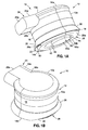
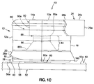
- FIGS. 1A-1C show one of the embodiments of the aero-contouring apparatus 10, such as in the form of an aero-contouring apparatus 10a, for aero-contouring a surface 50 (see FIG. 1 C) to be aero-contoured of an aerodynamically functional coating 214 (see FIG. 8 ) applied to the structure 52 (see FIG. 1C ).
- FIG. 1A is an illustration of a side perspective view of the embodiment of the aero-contouring apparatus 10, such as in the form of aero-contouring apparatus 10a, of the disclosure for aero-contouring the surface 50 (see FIG. 1C ).
- FIG. 1B is an illustration of a top perspective view of the aero-contouring apparatus 10, such as in the form of aero-contouring apparatus 10a, of FIG. 1A .
- FIG. 1C is an illustration of a side view of the aero-contouring apparatus 10, such as in the form of aero-contouring apparatus 10a, of FIG. 1A showing various internal components in phantom lines.
- the aero-contouring apparatus 10 comprises a housing assembly 12.
- the housing assembly 12 may be in the form of a closed housing assembly 12a (see FIGS. 1A , 2A , 2C , 5A ), or the housing assembly 12 may be in the form of an open housing assembly 12b (see FIG. 4A ).
- the housing assembly 12 comprises a top end 14a, a bottom end 14b, and a body portion 16 there between.
- FIGS. 1A-1C the housing assembly 12 comprises a top end 14a, a bottom end 14b, and a body portion 16 there between.
- the body portion 16 may comprise a lower skirt portion 20 that flares outwardly at the bottom end 14b of the body portion 16 to facilitate collection of abrading debris 138 during aero-contouring of the surface 50 with the aero-contouring apparatus 10.
- a lip portion 18 may be formed in the skirt portion 20 (see FIGS. 1A-1C ) at the bottom end 14b (see FIGS. 1A-1C ).
- the housing assembly 12 may further comprise an open interior portion 22 (see FIG. 1A ) at the bottom end 14b (see FIG. 1A ).
- the open interior portion 22 (see FIG. 1A ) is preferably of a sufficient size and configuration to receive for installation within the housing assembly 12, at least a motor assembly 80 (see FIG. 1C ), an engagement force/tilt limiting member 28 (see FIGS. 1A-1C ) and an abrading unit 60 (see FIGS. 1A , 1C ).
- the housing assembly 12 may further comprise a grip portion 24 configured for manually holding the aero-contouring apparatus 10 during manual operation.
- the grip portion 24 (see FIGS. 1A-1C ) may be in the form of a side extending grip portion 24a (see FIGS. 1A-1C , 2C ), a top grip portion 24b (see FIGS. 2A-2B ), a trigger handle grip portion 24c (see FIGS. 4A-5B ), or another suitable grip portion 24.
- the grip portion 24 has a first end 26a and a second end 26b. The second end 26b (see FIGS.
- the grip portion 24 (see FIG. 1A ) and the body portion 16 (see FIG. 1A ) of the housing assembly 12 (see FIG. 1A ) are preferably made of a strong but flexible material, such as a strong, flexible plastic, nylon, vinyl or other suitable strong, flexible material.
- the aero-contouring apparatus 10 further comprises an engagement force/tilt limiting member 28 coupled to the housing assembly 12.
- the engagement force/tilt limiting member 28 (see FIGS. 1A , 2A ) is preferably in the form of a machined ring member 28a (see FIGS. 1A , 2A ).
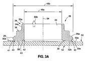
- FIG. 3A is an illustration of a sectional view of the engagement force/tilt limiting member 28 of the aero-contouring apparatus 10 (see FIGS. 1A , 2A ) of the disclosure for aero-contouring a surface 50 of a structure 52.
- FIG. 2B also shows a side perspective view of the engagement force/tilt limiting member 28, such as in the form of machined ring member 28a.
- the engagement force/tilt limiting member 28 such as in the form of machined ring member 28a, has a first end 32a, a second end 32b, a body portion 36 there between, and a central through opening 44 (see FIGS.
- the bottom end 32b (see FIG. 3A ) of the engagement force/tilt limiting member 28 (see FIG. 3A ) is configured to contact the surface 50 (see FIG. 3A ) to be aero-contoured of the aerodynamically functional coating 214 (see FIG. 6 ).
- the body portion 36 of the engagement force/tilt limiting member 28, such as in the form of machined ring member 28a, comprises a coupling portion 34 having a plurality of coupling elements 34a formed in the coupling portion 34.
- the coupling elements 34a may be in the form of snap fit coupling elements such as serrated snap fit coupling elements, or other suitable coupling elements.
- the coupling elements 34a are configured to couple, and preferably snap fit, with a plurality of coupling element engagement portions 82 (see FIG. 2B ) formed in an interior wall 78 (see FIG. 2B ) of the body portion 16 of the housing assembly 12 (see FIG. 2B ).
- the body portion 36 of the engagement force/tilt limiting member 28, such as in the form of machined ring member 28a, comprises a base portion 38 having an outer rim portion 29 (see FIG. 3A ) with a non-squared edge configuration 30.
- the non-squared edge configuration 30 of the outer rim portion 29 may comprise a beveled configuration 30a.
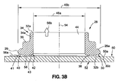
- FIG. 3B is an illustration of a sectional view of an engagement force/tilt limiting member 28, such as in the form of machined ring member 28a, of the aero-contouring apparatus (see FIGS. 1A , 2A ) of the disclosure showing another example of a non-squared edge configuration 30.
- the non-squared edge configuration 30 of the outer rim portion 29 may comprise a continuous curve configuration 30c.
- the non-squared edge configuration 30 of the outer rim portion 29 may comprise a radiused configuration 30b.
- the outer rim portion 29 may also have another suitable non-squared edge configuration.
- the engagement force/tilt limiting member 28, such as in the form of machined ring member 28a, has an inner diameter 46a equal to the diameter of the central through opening 44, and has in outer diameter 46b equal to the outermost diameter of the outer rim portion 29.
- FIG. 3A further shows a centerline 54 running through the center of the central through opening 44.
- the bottom end 32b of the engagement force/tilt limiting member 28, such as in the form of machined ring member 28a is flat or substantially flat with the only opening being the central through opening 44.
- the bottom end 32b of the engagement force/tilt limiting member 28, such as in the form of machined ring member 28a has a plurality of countersink openings 48.
- the countersink openings 48 may be spaced an equidistance apart from each other.
- each of the countersink openings 48 is configured to receive a countersink element 108.
- the engagement force/tilt limiting member 28 such as in the form of machined ring member 28a, comprises a converging nozzle portion 40 and a diverging nozzle portion 42.
- the converging nozzle portion 40 has a first tapered portion 41, that preferably tapers inwardly and downwardly from the outermost portion of the outer rim portion 29 to the bottom end 32b of the engagement force/tilt limiting member 28. As shown in FIGS.
- the diverging nozzle portion 42 has a second tapered portion 43, that preferably tapers outwardly and upwardly from the bottom end 32b of the engagement force/tilt limiting member 28 toward the central through opening 44.
- the geometry of the converging nozzle portion 40 and the diverging nozzle portion 42 effectively produces a convergent-divergent nozzle at the surface 50 (see FIGS. 3A-3B ) being aero-contoured or abraded.
- This convergent-divergent nozzle comprises the first tapered portion 41 (see FIGS. 3A-3B ) and the second tapered portion 43 (see FIGS. 3A-3B ) and accelerate the supplied suction driven air flow velocity 56a (see FIGS. 3A-3B ) at the surface 50 being aero-contoured or abraded. This, in turn, may improve collection of the abrading debris 138 (see FIG. 6 ) by the developed geometry of the convergent-divergent nozzle feature.
- the converging nozzle portion 40 (see FIGS. 3A-3B ) and the diverging nozzle portion 42 (see FIGS. 3A-3B ) together preferably accelerate a suction driven air flow velocity 56a (see FIG. 3A ) flowing within a gap at the surface 50 (see FIGS. 3A-3B ) to entrain abrading debris 138 (see FIG. 6 ) for collection in the debris collection system 97 (see FIGS. 2B , 5A ), such as external vacuum system 100 (see FIGS. 2B , 5A ).
- the gap 58 between the bottom end 32b of the engagement force/tilt limiting member 28, such as in the form of machined ring member 28a, and the surface 50, such as the coated or painted surface 50a, is very narrow.
- the converging nozzle portion 40 (see FIGS. 3A-3B ) and the diverging nozzle portion 42 (see FIGS. 3A-3B ) preferably accelerate the suction driven air flow velocity 56a (see FIGS. 3A-3B ) within the gap 58 (see FIGS. 3A-3B ) and draw up a suction drawn air flow velocity 56b (see FIGS. 3A-3B ) through the central opening 44 (see FIGS. 3A-3B ).
- the aero-contouring apparatus 10 provides a confined flow path to collect abrading debris 138 (see FIG. 6 ) for any aero-contouring apparatus 10 configured for use with a debris collection system 97 (see FIG. 2B ), such as an external vacuum system 100 (see FIG. 2B ).
- the engagement force/tilt limiting member 28, such as in the form of machined ring member 28a, is preferably made of a material that prevents or minimizes transfer of any contaminant material or residue material from the engagement force/tilt limiting member 28 (see FIGS. 3A-3B ) to the surface 50 (see FIGS. 3A-3B ) to be aero-contoured.
- the engagement force/tilt limiting member 28, such as in the form of machined ring member 28a is preferably constructed of a material, such as a strong and stiff acetal resin material, a strong and stiff nylon material, or another suitably strong and stiff plastic material, that prevents or minimizes transfer of any contaminant material or residue material from the engagement force/tilt limiting member 28 (see FIGS.
- the engagement force/tilt limiting member 28, such as in the form of machined ring member 28a, is made of DELRIN acetal resin.
- DELRIN is a registered trademark of E.I. Du Pont de Nemours and Company of Wilmington, Delaware.
- any other parts of the aero-contouring apparatus 10 that may directly contact the surface 50 are also preferably made of a material that prevents or minimizes transfer of any contaminant material or residue material from the engagement force/tilt limiting member 28 (see FIGS. 3A-3B ) to the surface 50 (see FIGS. 3A-3B ) to be aero-contoured.
- the aero-contouring apparatus 10 further comprises a motor assembly 80 disposed within the housing assembly 12.
- the motor assembly 80 comprises a motor unit 90 and a drive unit 84.
- the motor unit 90 (see FIGS. 1C , 2C ) may comprise an air motor element 90a (see FIG. 1C , 2C ).
- the motor unit 90 may comprise an electric motor element 90b (see FIG. 6 ) or another suitable motor unit.
- the drive unit 84 has a first end 85a and a second end 85b. At the first end 85a (see FIG. 1 C) is an abrading unit engagement portion 86 (see FIGS. 1C , 2C ). At the first end 85b (see FIG. 1C ) is a motor unit engagement portion 88 (see FIGS. 1C , 2C ).
- the drive unit 84 may preferably comprise a rotary drive shaft adaptor unit or another suitable drive mechanism.
- the drive unit 84 (see FIG. 1C ) is preferably configured to drive or rotate an abrading unit 60 (see FIG. 1 C) , such as in the form of a sanding unit 60a (see FIG. 1C ).
- the abrading unit engagement portion 86 (see FIG. 1C ) is preferably attached to the abrading unit 60 (see FIG. 1C ).
- the motor unit engagement portion 88 (see FIG. 1C ) is preferably attached to the motor unit 90 (see FIG. 1C ).
- the aero-contouring apparatus 10 further comprises the abrading unit 60 (see FIG. 1C ) coupled to the drive unit 84 (see FIG. 1C ) and inserted through the central opening 44 (see FIG. 2C ) in non-contact communication with the engagement force/tilt limiting member 28 (see FIG. 2C ), such as in the form of machined ring member 28a (see FIG. 2C ).
- the abrading unit 60 (see FIG. 2C ) is preferably attached to the abrading unit engagement portion 86 (see FIGS. 1C , 2C ) driven by the drive unit 84 (see FIGS. 1C , 2C ) in a random orbit motion 132 (see FIG. 6 ) on the surface 50 (see FIG. 1C ).
- the random orbit motion 132 may produce a random orbit abrading or sanding pattern by simultaneously spinning the abrading unit 60 and moving the abrading unit 60 in an ellipse.
- the abrading unit 60 such as in the form of sanding unit 60a, is preferably in an offset position 74 as compared to the engagement force/tilt limiting member 28 and as compared to the housing assembly 12 of the aero-contouring apparatus 10.
- the abrading unit 60 such as in the form of sanding unit 60a (see FIG. 2C ), comprises an abrading pad 62, an abrading media 64 attached to one side of the abrading pad 62, and a connector element 66 attached to the other side of the abrading pad 62.
- the abrading pad 62 has a first side 63a and a second side 63b.
- the abrading pad 62 may preferably be in the form of a foam pad and hook element 62a (see FIG. 2B ).
- the foam pad and hook element 62a may comprise a foam pad layer on the first side 63a and a hook layer on the second side 63b.
- the hook layer may be attached to the foam pad layer with an adhesive material.
- the connector element 66 has a first side 67a and a second side 67b.
- the connector element 66 may preferably be in the form of a twist lock connector 66a having a locking element 68, such as in the form of a twist lock element 68a.
- the locking member 68 is preferably attached to the first side 67a of the connector element 66 and configured for connection to the drive unit 84 (see FIGS. 1C , 2C ).
- the first side 63a of the abrading pad 62 is preferably attached to the second side 67b of the connector element 66 with an adhesive material.
- the locking member 68 of the connector element 66 is preferably configured for insertion through an opening 70 and is configured for attachment to a connector element receiving element 72 positioned in the housing assembly 12.
- the abrading media 64 has a first side 65a and a second side 65b.
- the first side 65a (see FIG. 2B ) of the abrading media 64 is preferably attached to the second side 63b (see FIG. 2B ) of the abrading pad 62 (see FIG. 2B ).
- the abrading media 64 may preferably be in the form of an abrasive film and loop element 64a (see FIG. 2B ).
- the abrasive film and loop element 64a may comprise a loop layer on the first side 65a and an abrasive sanding film or sanding paper on the second side 65b.
- the abrasive sanding film or sanding paper of the abrading media 64 preferably has a grit size sufficient for finish quality requirements.
- the abrading media 64 is designed to be a consumable item that is consumed or used up after one or more uses and may be replaced.
- the abrading unit 60 including the abrading pad 62 (see FIG. 2B ), the abrading media 64 (see FIG. 2B ), the connector element 66 (see FIG. 2A ), preferably has an outer diameter 76 with a length in a range of from about one (1) inch (about 2.5cm) to about less than three (3) inches (about less than 7.5cm), and more preferably, has an outer diameter 76 with a length in a range of from about one (1) inch (about 2.5cm) to about one and a quarter (1.25) inch (about 3cm).
- a random orbit motion 132 (see FIG. 6 ) of the abrading unit 60 (see FIG. 2B ), such as in the form of a one and a quarter (1.25) inch (3cm) diameter abrading unit 60.
- the aero-contouring apparatus 10 such as in the form of abrading apparatus 11 (see FIG. 6 ), preferably uses an abrading media 64 (see FIG. 2B ), such as in the form of abrasive film and loop element 64a (see FIG. 2B ), that is one and a quarter (1.25) inch (3cm) diameter or slightly smaller in diameter to limit the aero-contoured or abraded area to that immediately near a coating edge 222 (see FIG. 6 ) or surface inclusion 224 (see FIG. 6 ) defect, making the aero-contouring process more controllable, and reducing the area with a visual difference between aero-contoured and non-aero-contoured areas after the aero-contouring.
- an abrading media 64 see FIG. 2B
- abrasive film and loop element 64a see FIG. 2B
- the aero-contouring apparatus 10 preferably maintains the second side 65b (see FIG. 1A ) of the abrading unit 60 (see FIGS. 1A , 1C ) almost flush with the surface 50 (see FIG. 1C ), such as the coated or painted surface 50a (see FIG. 1C ), to facilitate control of the aero-contouring apparatus 10, from tilting more than a few degrees and abrading or sanding through the aerodynamically functional coating 214 (see FIG. 6 ).
- the housing assembly 12, the motor assembly 80, the engagement force/tilt limiting member 28, and the abrading unit 60 together comprise an aero-contouring apparatus 10 for aero-contouring the surface 50 to be aero-contoured.
- the engagement force/tilt limiting member 28 (see FIG. 6 ) mechanically limits both an engagement force 134 (see FIG. 6 ) and any tilting motion 136 (see FIG. 6 ) of the abrading unit 60 (see FIG. 6 ) with respect to the surface 50 (see FIG. 6 ).
- the engagement force/tilt limiting member 28 mechanically limits the engagement force of the abrading unit 60 (see FIG. 2B ), and in particular, the abrading media 64 (see FIG. 2B ), with a surface 50 to be aero-contoured.
- the engagement force/tilt limiting member 28 (see FIG. 6 ) mechanically limits any tilting of the abrading unit 60, and in particular, the abrading pad 62 (see FIG. 2B ) and the abrading media 64 (see FIG. 2B ), with respect to the surface 50 (see FIGS. 1C , 4A ) to prevent excessive sanding pressure on one side of the sanding unit 60, such as abrading pad 62 or the abrading media 64, which may result in gouging of the surface 50.
- the aero-contouring apparatus 10 with the engagement force/tilt limiting member 28 is preferably designed to keep the abrading media 64 (see FIG. 2B ) in parallel or tangential contact with the surface 50 which may be flat or curved, that is to be aero-contoured or abraded.
- the aero-contouring apparatus 10 such as in the form of abrading apparatus 11 (see FIG. 6 ), comprises a debris collection system 97 (see FIG. 2B ), such as an external vacuum system 100 (see FIG. 2B ), for removing any abrading debris 138 (see FIG. 6 ).
- the aero-contouring apparatus 10 may be in the form of an aero-contouring apparatus 10b, having a vacuum outlet port 98 configured for attachment to a vacuum attachment element 101 (see FIG. 2 ) connected to a debris collection system 97 (see FIG. 2B ), such as an external vacuum system 100 (see FIG. 2B ).
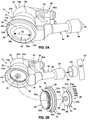
- FIG. 2A is an illustration of a bottom perspective view of the embodiment of the aero-contouring apparatus 10, such as in the form of aero-contouring apparatus 10b, for aero-contouring the surface 50 (see FIGS. 1C , 4A , 8 ).
- the aero-contouring apparatus 10 is used with a debris collection system 97 (see FIG. 2B ), such as an external vacuum system 100 (see FIG. 2B).
- FIG. 2B is an illustration of an exploded view of the aero-contouring apparatus 10, such as in the form of aero-contouring apparatus 10b, of FIG. 2A , showing the engagement force/tilt limiting member 28 and the abrading unit 60 separated from the housing assembly 12 of the aero-contouring apparatus 10 (see FIG. 2B ).
- the aero-contouring apparatus 10 comprises the housing assembly 12, such as in the form of closed housing assembly 12a, having a top end 14a, a bottom end 14b, and a grip portion 24, such as in the form of top grip portion 24b.
- the aero-contouring apparatus 10 comprises the engagement force/tilt limiting member 28 having a non-squared edge configuration 30, such as comprising a radiused configuration 30a, and the abrading unit 60 inserted through the central through opening 44 (see FIG. 2A ).
- the aero-contouring apparatus 10 comprises a limiting valve 92 attached to the motor unit 90, such as an air motor element 90a.
- the limiting valve 92 preferably comprises an air motor exhaust restrictor, for example, an air motor variable exhaust restrictor that regulates the revolutions per minute (rpms) of the drive unit 84 which drives or rotates the attached abrading unit 60.
- the aero-contouring apparatus 10 comprises an exhaust assembly 94 having an exhaust tube portion 96, a vacuum outlet port 98 with an attachment end 99.
- the attachment end 99 of the vacuum outlet port 98 is preferably configured for attachment with the vacuum attachment element 101 of the debris collection system 97, such as the external vacuum system 100.
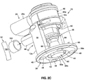
- FIG. 2C is an illustration of another embodiment of the aero-contouring apparatus 10, such as in the form of aero-contouring apparatus 10c, comprising another version of the engagement force/tilt limiting member 28 and another version of the housing assembly 12.
- the engagement force/tilt limiting member 28 has the plurality of countersink openings 48
- the housing assembly 12 is preferably in the form of a closed housing assembly 12a.
- FIG. 2C shows the aero-contouring apparatus 10c comprising a vacuum outlet port 98 configured for attachment to a vacuum attachment element 101 of a debris collection system 97, such as an external vacuum system 100.
- the aero-contouring apparatus 10 may be configured for performing touch-up aero-contouring, for example, of small surface areas.
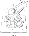
- FIG. 4A is an illustration of a front perspective view of another embodiment of an aero-contouring apparatus 10, such as in the form of aero-contouring apparatus 10d, of the disclosure for aero-contouring a surface 50 of a structure 52.
- the aero-contouring apparatus 10d of FIGS. 4A-4E is preferably configured for touch-up applications of the surface 50 of the structure 52.
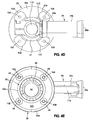
- FIG. 4B is an illustration of a side view of the aero-contouring apparatus 10, such as in the form of aero-contouring apparatus 10d, of FIG. 4A .
- FIG. 4C is an illustration of a front view of the aero-contouring apparatus 10, such as in the form of aero-contouring apparatus 10d, of FIG. 4A .
- FIG. 4D is an illustration of a top plan view of the aero-contouring apparatus 10, such as in the form of aero-contouring apparatus 10d, of FIG. 4A .
- FIG. 4E is an illustration of a bottom plan view of the aero-contouring apparatus o 10d f FIG. 4A .
- the housing assembly 12 comprises one or more cut-out portions 102 forming a viewing feature 103 enabling an operator to view an aero-contouring location 105 on the surface 50 of the structure 52 to be aero-contoured during touch-up aero-contouring with the aero-contouring apparatus 10.
- the aero-contouring apparatus 103 shown in FIGS. 4A-4E provides a way of easily locate and view the aero-contouring location 105 to be aero-contoured or abraded while providing the prior mechanical limiting feature to prevent excessive sanding or gouging.
- the housing assembly 12 is in the form of an open housing assembly 12b having leg portions 104 with openings 106 for receiving countersink elements 108 (see FIG. 4E ).
- the housing assembly 12 may comprise a grip portion 24, such as in the form of a trigger handle grip portion 24c, that extends from the top end 14a of the housing assembly 12.
- the trigger handle grip portion 24c comprises a first end 26a, a second end 26b, and a trigger handle portion 114 (see FIG. 4A ).
- the trigger handle grip portion 24c houses the motor unit 90, and the second end 26b of the trigger handle grip portion 24c is attached to the housing assembly 12.
- the housing assembly 12 comprises a right angle gear box 110 and exhaust ports 112.
- the aero-contouring apparatus 10 such as in the form of aero-contouring apparatus 10d, comprises the engagement force/tilt limiting member 28 having an outer rim portion 29 with a non-squared edge configuration 30.
- the non-squared edge configuration 30 may comprise the radiused configuration 30b (see FIG. 4B ).
- the aero-contouring apparatus 10, such as in the form of aero-contouring apparatus 10d comprises the motor assembly 80 comprising the drive unit 84, the abrading unit engagement portion 86, and the motor unit engagement portion 88.
- the aero-contouring apparatus 10 comprises the engagement force/tilt limiting member 28, such as in the form of machined ring member 28a.
- the engagement force/tilt limiting member 28, such as in the form of machined ring member 28a preferably has on the bottom end 32b, the plurality of countersink openings 48 having countersink elements 108, and an outer rim portion 29 with a non-squared edge configuration 30, such as comprising a radiused configuration 30b.
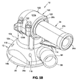
- FIG. 5A is an illustration of a back perspective view of another embodiment of an aero-contouring apparatus 10, such as in the form of aero-contouring apparatus 10e, where the aero-contouring apparatus 10 may be used with a clamp fixture 120, for aero-contouring a surface 50.
- the aero-contouring apparatus l0e with the clamp fixture 120 is preferably configured for use with a debris collection system 97, such as an external vacuum system 100 and configured for attachment to the vacuum attachment element 101 of the debris collection system 97, such as the external vacuum system 100.
- FIG. 5B is an illustration of a front perspective view of the aero-contouring apparatus 10, such as in the form of aero-contouring apparatus 10e, of FIG. 5A .
- the clamp fixture 120 comprises a first portion 120a attached to a second portion 120b via attachment portions 122.
- the clamp fixture 120 may be an extension of the top end 14a of the housing assembly 12.
- the housing assembly 12 is a substantially closed housing assembly 12, with openings 118 for receiving attachment elements (not shown) to enable attachment to the engagement force/tilt limiting member 28, such as in the form of machined ring member 28a.
- the engagement force/tilt limiting member 28 comprises a machined ring member 28a with a non-squared edge configuration 30, such as comprising a radiused configuration 30b.
- the housing assembly 12 comprises a grip portion 24, such as in the form of trigger handle grip portion 24c, having a first end 26a, a second end 26b, and a trigger portion 114.
- the housing assembly 12 comprises a vacuum outlet port 98 having an attachment end 99 configured for attachment to the vacuum attachment element 101 (see FIG. 5A ) of the debris collection system 97 (see FIG. 5A ), such as the external vacuum system 100 (see FIG. 5A ).
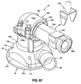
- the aero-contouring apparatus 10 may be used not only for manual applications but for automated applications, for example, robotic applications. If the aero-contouring apparatus 10 (see FIGS. 1A , 2A , 4A , 5A ) is used for automated applications, for example, robotic applications, a compliant end effector coupling 124 (see FIG. 5C ) may be attached to the housing assembly 12 or integrally formed in the housing assembly 12.
- FIG. 5C is an illustration of a front perspective view of the aero-contouring apparatus 10, such as in the form of aero-contouring apparatus 10e, of FIG. 5B , that may be used for automated applications such as robotic applications.
- the compliant end effector coupling 124 (see FIG. 5C ) is preferably configured for attachment to a robotic device 126 (see FIG. 5C ).
- the trigger portion 114 (see FIG. 5B ) may be removed from the aero-contouring apparatus 10e (see FIG. 5C ) and replaced with the compliant end effector coupling 124 (see FIG. 5C ), as the robotic device 126 is designed to hold or grip the grip portion 24 via the compliant end effector coupling 124 (see FIG. 5C ).
- FIG. 6 is a block diagram of an example of an aero-contouring system 130 incorporating an embodiment of the aero-contouring apparatus 10 of the disclosure.
- the aero-contouring system 130 (see FIG. 6 ) comprises an abrading system 131 (see FIG. 6 ), for example, a sanding and polishing system.
- the aero-contouring system 130 comprises a structure 52 coated with an aerodynamically functional coating 214 having a surface 50 to be aero-contoured.
- the structure 52 comprises one or more of a tail 208 of an air vehicle 200, including a vertical stabilizer tail portion 210 and horizontal stabilizer tail portions 212; wings of an air vehicle 200, including winglets 206; fuselage 202 of an air vehicle 200; and nacelles 213 of an air vehicle 200.
- the structure 52 may be coated with an aerodynamically functional coating 214 comprising an aerodynamically functional film element 220.
- the aero-contouring system 130 further comprises an aero-contouring apparatus 10 for aero-contouring the surface 50.
- the aero-contouring apparatus 10 comprises a housing assembly 12 and a motor assembly 80 disposed within the housing assembly 12.
- the motor assembly 80 comprises a motor unit 90 and a drive unit 84.
- the aero-contouring apparatus 10 of the aero-contouring system 130 further comprises an engagement force/tilt limiting member 28 coupled to the housing assembly 12.
- the engagement force/tilt limiting member 28 has a central opening 44 and has a bottom end 32b (see FIGS. 3A-3B ) configured to contact a surface 50 to be aero-contoured of an aerodynamically functional coating 214 applied to a structure 52.
- the engagement force/tilt limiting member 28 comprises a converging nozzle portion 40 and a diverging nozzle portion 42 that together accelerate a suction driven air flow velocity 56a at the surface 50 to be aero-contoured to entrain abrading debris 138 for collection in the debris collection system 97 (see also FIGS. 2B , 2C , 5A ), such as the external vacuum system 100 (see also FIGS. 2B , 2C , 5A ).
- the aero-contouring apparatus 10 of the aero-contouring system 130 further comprises an abrading unit 60 coupled to the drive unit 84 and inserted through the central opening 44 in non-contact communication with the engagement force/tilt limiting member 28.
- the abrading unit 60 (see FIG. 1 C) is driven by the drive unit 84 (see FIG. 1C ) in a random orbit motion 132 (see FIG. 6 ) on the surface 50.
- the engagement force/tilt limiting member 28 mechanically limits both an engagement force 134 (see FIG. 6 ) and any tilting motion 136 (see FIG. 6 ) of the abrading unit 60 (see FIG. 6 ) with respect to the surface 50 (see FIG. 6 ).
- the aero-contouring system 130 may comprise a debris collection system 97, such as an external vacuum system 100 (see FIG. 6 ), for attachment to the aero-contouring apparatus 10, where the aero-contouring apparatus 10 further comprises a vacuum outlet port 98 (see FIG. 6 ).
- a debris collection system 97 such as an external vacuum system 100 (see FIG. 6 )
- the aero-contouring apparatus 10 further comprises a vacuum outlet port 98 (see FIG. 6 ).
- the aero-contouring apparatus 10 may be configured for performing touch-up aero-contouring of the surface 50.
- the housing assembly 12 comprises one or more cut-out portions 102 forming a viewing feature 103 enabling an operator to view an aero-contouring location 105 on the surface 50 during touch-up aero-contouring with the aero-contouring apparatus 10.
- FIG. 7 is a flow diagram of an aero-contouring method 150 of the disclosure.
- the method 150 of aero-contouring may be performed manually or may be automated.
- the method 150 comprises step 152 of contacting with an aero-contouring apparatus 10 (see FIGS. 1A-2C , 4A-5C ) a surface 50 to be aero-contoured of an aerodynamically functional coating 214 (see FIG. 8 ) applied to a structure 52.
- the aero-contouring apparatus 10 comprises a housing assembly 12 and a motor assembly 90 disposed within the housing assembly 12.
- the motor assembly comprises a motor unit and a drive unit 84.
- the aero-contouring apparatus 10 further comprises an engagement force/tilt limiting member 28 coupled to the housing assembly 12.
- the engagement force/tilt limiting member 28 has a central opening 44.
- the aero-contouring apparatus 10 further comprises an abrading unit 60 coupled to the drive unit 84 and inserted through the central opening 44 in non-contact communication with the engagement force/tilt limiting member 28.
- the step 152 of contacting the surface 50 with the aero-contouring apparatus 10 preferably comprises contacting the surface 50 (see FIGS. 1C , 4A ) with an abrading unit 60 (see FIGS. 1C , 4A ) of the aero-contouring apparatus 10 (see FIGS. 1C , 4A ), where the abrading unit 60 has an outer diameter 76 (see FIG. 2A ) with a length in a range of from about 1 inch (about 2.5cm) to about 1.25 inch (about 3cm).
- the step 152 of contacting the surface 50 further comprises forming the engagement force/tilt limiting member 28 (see FIGS. 1A , 4A ) of a material that prevents or minimizes transfer of any contaminant material or residue material from the engagement force/tilt limiting member 128 to the surface 50 to be aero-contoured.
- the method 150 further comprises step 154 of moving the aero-contouring apparatus 10 (see FIGS. 1A-2C , 4A-5C ) in a random orbit motion 132 (see FIG. 6 ) on the surface 50 (see FIGS. 1C , 4A ) to abrade and smooth the surface 50 (see FIGS. 1C , 4A ).
- the abrading unit 60 (see FIG. 2B ) of the aero-contouring apparatus 10 may be moved in a random orbit motion 132 (see FIG. 6 ) on the surface 50 (see FIGS. 1C , 4A ) to abrade and smooth the surface 50 (see FIGS. 1C , 4A ).
- Abrading and smoothing the surface 50 (see FIGS. 1C , 4A ) of the aerodynamically function coating 214, and/or the aerodynamically functional element 220 preferably comprise using the aero-contouring apparatus 10 (see FIGS. 1A-2B , 4A-5B ), such as in the form of abrading apparatus 11 (see FIG. 11), to abrade and smooth coating edges 222 (see FIG. 6 ), such as paint edges and flow surfaces 226 (see FIG. 6 ).
- abrading and smoothing the surface 50 (see FIGS. 1C , 4A ) of the aerodynamically functional coating 214, and/or the aerodynamically functional element 220 preferably comprise using the aero-contouring apparatus 10 (see FIGS.
- the method 150 further comprises step 156 of mechanically limiting with the engagement force/tilt limiting member 28 (see FIGS. 2A , 4A ) an engagement force 134 (see FIG. 6 ) and any tilting motion 136 (see FIG. 6 ) of the abrading unit 60 (see FIG. 6 ) with respect to the surface 50 (see FIGS. 1C , 3 , 4A ).
- the method 150 further comprises step 158 of removing or minimizing any surface inclusions 224 (see FIG. 6 ) and coating edges 222 (see FIG. 6 ) on the surface 50 (see FIG. 6 ) without causing excessive engagement force 134 (see FIG. 6 ) to the surface 50 and without gouging of the surface 50 (see FIG. 6 ).
- Surface inclusions 224 may comprise dust particles, debris particles, dry coating overspray, lint, or other particles or contaminants that may be present on the surface 50 (see FIGS. 1C , 4A ) during or after aero-contouring of the surface 50 (see FIGS. 1C , 4A ) with the aero-contouring apparatus 10 (see FIGS.
- Three-dimensional surface discontinuities that may occur from such surface inclusions 224 may be even lower than coating edges 222, such as in the form of right angle (90 degrees) steps.
- Abrading debris 138 may be removed with a debris collection system 97 (see FIGS. 2B-2C ), such as an external vacuum system 100 (see FIGS. 2B-2C ), that may be attached to the aero-contouring apparatus 10 (see FIGS. 2B-2C ).
- the method 150 may further comprise optional step 160 of using the engagement force/tilt limiting member 28 (see FIGS. 2B , 3 ) to accelerate the suction driven air flow velocity 56a (see FIG. 6 ) at the surface 50 to entrain abrading debris 138 (see FIG. 6 ) for collection in the debris collection system 97 (see FIGS. 2B , 2C , 5A ), such as the external vacuum system 100 (see FIGS. 2B , 2C , 5A ).
- the step 160 of using the engagement force/tilt limiting member 28 (see FIGS. 3 , 6 ) to accelerate the suction driven air flow velocity 56a (see FIG. 6 ) comprises using a converging nozzle portion 40 (see FIG. 6 ) and a diverging nozzle portion 42 (see FIG. 6 ) formed on the engagement force/tilt limiting member 28 (see FIG. 6 ) to accelerate the suction driven air flow velocity 56a (see FIG. 6 ).
- the method 150 may further comprise optional step 162 of enabling touch-up aero-contouring on the surface 50 with the aero-contouring apparatus 10 (see FIG. 4A ) by removing one or more cut-out portions 102 (see FIG. 4A ) from the housing assembly 12 (see FIG. 4A ) to form a viewing feature 103 (see FIG. 4A ) to view an aero-contouring location 105 (see FIG. 4A ) on the surface 50 (see FIG. 4A ) of the structure 52 (see FIG. 4A ).
- FIG. 8 is a perspective view of an air vehicle 200, such as in the form of an aircraft 200a, that may incorporate one or more surfaces 50 of a structure 52, such as exterior aerodynamic surfaces 53, of a structure 52, where the one or more surfaces 50 may be aero-contoured with one or more embodiments of the aero-contouring apparatus 10 of the disclosure.
- the air vehicle 200 such as in the form of aircraft 200a, comprises a fuselage 202, wings 204, winglets 206, a tail 208 comprising a vertical tail portion 210 and horizontal tail portions 212, and nacelles 213.
- the aircraft 200a shown in FIG. 8 is generally representative of a commercial passenger aircraft having one or more structures 52 that may be coated with an aerodynamically functional coating 214, such as in the form of a decorative coating 216 (see FIG. 6 ) or a non-decorative coating 218 (see FIG. 6 ), the teachings of the disclosed embodiments may be applied to other passenger aircraft.
- the teachings of the disclosed embodiments may be applied to cargo aircraft, military aircraft, rotorcraft, and other types of aircraft or aerial vehicles, as well as aerospace vehicles, satellites, space launch vehicles, rockets, and other aerospace vehicles, that use decorative coatings 216 or non-decorative coatings 218.
- FIG. 9 is a flow diagram of an aircraft manufacturing and service method 300.
- FIG. 10 is a block diagram of an example of an aircraft 316. Referring to FIGS. 9-10 , embodiments of the disclosure may be described in the context of the aircraft manufacturing and service method 300 as shown in FIG. 9 , and the aircraft 316 as shown in FIG. 10 .
- exemplary aircraft manufacturing and service method 300 may include specification and design 302 of the aircraft 316 and material procurement 304. During manufacturing, component and subassembly manufacturing 306 and system integration 308 of the aircraft 316 takes place. Thereafter, the aircraft 316 may go through certification and delivery 310 in order to be placed in service 312. While in service 312 by a customer, the aircraft 316 may be scheduled for routine maintenance and service 314 (which may also include modification, reconfiguration, refurbishment, and other suitable services).
- Each of the processes of the aircraft manufacturing and service method 300 may be performed or carried out by a system integrator, a third party, and/or an operator (e.g., a customer).
- a system integrator may include, without limitation, any number of aircraft manufacturers and major-system subcontractors.
- a third party may include, without limitation, any number of vendors, subcontractors, and suppliers.
- An operator may include an airline, leasing company, military entity, service organization, and other suitable operators.
- the aircraft 316 produced by the exemplary aircraft manufacturing and service method 300 may include an airframe 318 with a plurality of systems 320 and an interior 322.
- the plurality of systems 322 may include one or more of a propulsion system 324, an electrical system 326, a hydraulic system 328, and an environmental system 330. Any number of other systems may be included.
- an aerospace example is shown, the principles of the disclosure may be applied to other industries, such as the automotive industry.
- Methods and systems embodied herein may be employed during any one or more of the stages of the aircraft manufacturing and service method 300.
- components or subassemblies corresponding to component and subassembly manufacturing 306 may be fabricated or manufactured in a manner similar to components or subassemblies produced while the aircraft 316 is in service 312.
- one or more apparatus embodiments, method embodiments, or a combination thereof may be utilized during component and subassembly manufacturing 306 and system integration 308, for example, by substantially expediting assembly of or reducing the cost of the aircraft 316.
- one or more of apparatus embodiments, method embodiments, or a combination thereof may be utilized while the aircraft 316 is in service 312, for example and without limitation, to maintenance and service 314.
- Disclosed embodiments of the aero-contouring apparatus 10 (see FIGS. 1A-2C , 4A-5C ), examples of the aero-contouring system 130 (see FIG. 6 ), and embodiments of the method 150 (see FIG. 7 ) for aero-contouring have numerous advantages and provide for the aero-contouring of aerodynamically functional coatings 214 (see FIG. 6 ), such as decorative coatings 216 (see FIG. 6 ), that meet the aerodynamic requirements to retain desired flow characteristics, while also preserving decorative appearance.
- Disclosed embodiments of the aero-contouring apparatus 10 (see FIGS. 1A-2C , 4A-5C ), examples of the aero-contouring system 130 (see FIG. 6 ), and embodiments of the method 150 (see FIG.
- aero-contouring may be used to aero-contour not only decorative coatings 216 (see FIG. 6 ) on exterior aerodynamic surfaces 53 (see FIG. 8 ) of aircraft 200a (see FIG. 8 ), such as winglets 206 (see FIG. 8 ) or the vertical stabilizer tail portion 210 (see FIG. 8 ) where smooth coating or paint edges are desired to retain desired flow characteristics, but may also be used on non-decorative coatings 218 (see FIG. 6 ), such as may be applied to wings 204 (see FIG. 8 ) and horizontal stabilizer tail portions 212(see FIG. 8 ), where there may be a need for removal or repair of surface inclusions 224 (see FIG. 6 ).
- examples of the aero-contouring system 130 see FIG. 6
- embodiments of the method 150 for aero-contouring use an abrading unit 60 (see FIG. 2B ) with an abrading media 64 (see FIG. 2B ) having an outer diameter 76 (see FIG. 2A ) having a length of preferably 1.25 inch (3cm) or slightly smaller to limit the aero-contoured area to that immediately near the coating edge 222 (see FIG. 6 ) or surface inclusion 224 (see FIG. 6 ) defect, making the aero-contouring process more controllable, and reducing the area with a visual difference between aero-contoured and non-aero-contoured areas after the aero-contouring process.
- FIGS. 1A-2C , 4A-5C examples of the aero-contouring system 130 (see FIG. 6 ), and embodiments of the method 150 (see FIG. 7 ) for aero-contouring mechanically limit the engagement force 134 (see FIG. 6 ) of the abrading unit 60 (see FIGS. 1C , 2B ) with the surface 50 (see FIG. 1 C) to be aero-contoured, mechanically limit tilting of the abrading unit 60 (see FIGS. 1C , 2B ) with respect to the surface 50 (see FIG.
- FIGS. 1A-2C , 4A-5C examples of the aero-contouring system 130 (see FIG. 6 ), and embodiments of the method 150 (see FIG. 7 ) for aero-contouring provide an aero-contouring apparatus 10 that is preferably a random orbit motion type capable of random orbit motion 132 (see FIG. 6 ) to reduce the instance of swirl marks in the surface 50 (see FIG. 6 ) of the aerodynamically functional coating 214 (see FIG. 6 ).
- all parts of the aero-contouring apparatus 10 that contact coated or painted surfaces 50a are preferably made of a material that does not leave residue that can affect subsequent coating operations.
- disclosed embodiments of the aero-contouring apparatus 10 may reduce the amount of time and skill necessary to manually aero-contour the surface 50 to be aero-contoured and allows for less skilled operators to produce desired results by preventing or minimizing excessive pressure to the surface 50 to be aero-contoured and by preventing or minimizing gouging of the surface 50 by enabling tipping the aero-contouring apparatus 10 during operation.
- the method 130 of aero-contouring may be performed manually or may be automated.
- disclosed embodiments of the aero-contouring apparatus 10 may provide improved quality and aesthetics of surface finishes for marketing differentiation.
Landscapes
- Engineering & Computer Science (AREA)
- Mechanical Engineering (AREA)
- Grinding-Machine Dressing And Accessory Apparatuses (AREA)
- Application Of Or Painting With Fluid Materials (AREA)
- Finish Polishing, Edge Sharpening, And Grinding By Specific Grinding Devices (AREA)
- Coating Apparatus (AREA)
Description
- The disclosure relates generally to devices, methods and systems for aero-contouring surfaces of structures and collecting abrading debris, and more specifically, to devices, methods and systems for aero-contouring surfaces of aerodynamically functional coatings applied to structures of air vehicles, such as aircraft, and collecting abrading debris.
- Air vehicles, such as commercial passenger and cargo aircraft, may have exterior surfaces that are coated or painted with colorful and decorative designs. For example, such exterior surfaces of an air vehicle may include exterior surfaces of the tail, wings, fuselage, nacelles, or other exterior surfaces of the air vehicle. Such colorful and decorative designs may include airline livery designs which are standard paint schemes on aircraft that prominently display an airline's logo, name, or other identifying feature to provide branding and differentiation of the airline. Since airline livery designs may provide not only a decorative function, but also a branding and differentiation function, it is important that livery designs be consistently applied and with acceptable appearance, gloss, and long-term durability.
- In addition, maintaining desired air flow characteristics over coated or painted aircraft surfaces, such as airline livery designs, for example, coated or painted on the tail of an aircraft, may be challenging. In order to avoid impact on desired boundary layer characteristics during flight, there are allowable criteria for paint edges and waviness. There may also exist restrictions for three-dimensional surface discontinuities, such as those that may occur from inclusions caused by debris, dust, or dry coating overspray, which may be more stringent than for paint edges or for waviness.
- Known devices, systems and methods exist for abrading or sanding coated or painted surfaces in order to smooth and polish the surfaces. However, smoothing and polishing of coating or paint edges of aerodynamically functional coatings, such as decorative livery designs, may require a manual process performed at a very high skill level and may require an extensive amount of time to achieve. A manual process performed by skilled operators may not scale well to the large areas and manufacturing rates required for commercial aircraft livery due to the time and skill required. Moreover, if lesser-skilled operators are used to perform the abrading or sanding, excessive pressure may inadvertently be applied to the surface during abrading or sanding, and/or gouging of the surface may occur if the abrading or sanding device is inadvertently tipped to the side. Further, although sanding with known sanding devices may be performed on coating or paint edges of decorative livery designs, this may not be a viable manufacturing method for exterior decorative livery design coatings or paints where appearance, gloss and long-term durability may be required.
- Accordingly, there is a need in the art for improved devices, systems and methods for aero-contouring surfaces of aerodynamically functional coatings or paints of decorative designs, such as airline livery designs, applied to structures, such as structures of air vehicles, that provide advantages over known devices, systems and methods.
-
EP 2596908 discloses a machine tool for machining surfaces provided with a dynamic balancing system. The disclosure refers to a machine tool comprising a motor with a motor shaft adapted for performing a rotational movement around an axis of rotation, a working element adapted for performing an orbital or rotating orbital or random orbital movement, means for transforming the rotational movement of the shaft into the orbital or rotating orbital or random orbital movement of the working element, the transformation means comprising an eccentric attachment and a counter weight, wherein the attachment and the counter weight are connected torque proof to the shaft. -
US 3284961 discloses a polishing device. This disclosure relates to a polishing device and more particularly to a portable device for polishing spots on metallic and other surfaces which are to be examined under the reflected light microscope. -
US 2009/117834 discloses a heatless slurry system for use with a glass removal apparatus for restoring a glass surface. The system comprises a slurry container and a pump mounted externally relative to the container to prevent heating of the slurry as the system is operated. Vacuum pressure is created by activation of the pump to promote circulation of the slurry within the tool, thereby allowing the latter to be worked against the surface. - This need for improved devices, systems and methods for aero-contouring surfaces of aerodynamically functional coatings or paints of decorative designs, such as airline livery designs, applied to structures, such as structures of air vehicles, is satisfied by this disclosure. As discussed in the below detailed description, embodiments of the improved devices, systems and methods for aero-contouring surfaces of aerodynamically functional coatings or paints of decorative designs, such as airline livery designs, applied to structures, such as structures of air vehicles, may provide significant advantages over known methods and systems.
- In one embodiment of the disclosure, there is provided an aero-contouring apparatus according to claim1. The aero-contouring apparatus comprises a housing assembly. The aero-contouring apparatus further comprises a motor assembly disposed within the housing assembly. The motor assembly comprises a motor unit and a drive unit.
- The aero-contouring apparatus further comprises an engagement force/tilt limiting member coupled to the housing assembly. The engagement force/tilt limiting member has a central opening and has a bottom end configured to contact a surface to be aero-contoured of an aerodynamically functional coating applied to a structure. The aero-contouring apparatus further comprises an abrading unit coupled to the drive unit and inserted through the central opening in non-contact communication with the engagement force/tilt limiting member. The abrading unit is driven by the drive unit in a random orbit motion on the surface.
- The engagement force/tilt limiting member mechanically limits both an engagement force and any tilting motion of the abrading unit with respect to the surface. Optionally, the aero-contouring apparatus may comprise a vacuum outlet port configured for attachment to a debris collection device.
- In an example of the disclosure, there is provided an aero-contouring system. The aero-contouring system comprises a structure coated with an aerodynamically functional coating having a surface to be aero-contoured.
- The aero-contouring system further comprises an aero-contouring apparatus for aero-contouring the surface. The aero-contouring apparatus comprises a housing assembly and a motor assembly disposed within the housing assembly. The motor assembly comprises a motor unit and a drive unit.
- The aero-contouring system further comprises an engagement force/tilt limiting member coupled to the housing assembly. The engagement force/tilt limiting member has a central opening and has a bottom end configured to contact a surface to be aero-contoured of an aerodynamically functional coating applied to a structure. The aero-contouring system further comprises an abrading unit coupled to the drive unit and inserted through the central opening in non-contact communication with the engagement force/tilt limiting member. The abrading unit is driven by the drive unit in a random orbit motion on the surface. The engagement force/tilt limiting member mechanically limits both an engagement force and any tilting motion of the abrading unit with respect to the surface. Optionally, the aero-contouring system may comprise a debris collection system for attachment to the aero-contouring apparatus further comprising a vacuum outlet port.
- In another embodiment of the disclosure, there is provided a method for aero-contouring a surface of an aerodynamically functional coating applied to a structured according to
claim 10. The method comprises the step of contacting with an aero-contouring apparatus a surface to be aero-contoured of an aerodynamically functional coating applied to a structure. - The aero-contouring apparatus comprises a housing assembly and a motor assembly disposed within the housing assembly. The motor assembly comprises a motor unit and a drive unit. The aero-contouring apparatus further comprises an engagement force/tilt limiting member coupled to the housing assembly. The engagement force/tilt limiting member has a central opening. The aero-contouring apparatus further comprises an abrading unit coupled to the drive unit and inserted through the central opening in non-contact communication with the engagement force/tilt limiting member. Optionally, the aero-contouring apparatus may comprise a vacuum outlet port configured for attachment to a debris collection system.
- The method further comprises the step of moving the aero-contouring apparatus in a random orbit motion on the surface to abrade and smooth the surface. The method further comprises the step of mechanically limiting with the engagement force/tilt limiting member an engagement force and any tilting motion of the abrading unit with respect to the surface. The method further comprises the step of removing any surface inclusions and coating edges on the surface without resulting in excessive engagement force to the surface and without gouging the surface.
- According to an aspect of the present disclosure there is provided an aero-contouring apparatus comprising: a housing assembly, a motor assembly disposed within the housing assembly, the motor assembly comprising a motor unit and a drive unit, an engagement force/tilt limiting member coupled to the housing assembly, the engagement force/tilt limiting member having a central opening and having a bottom end configured to contact a surface to be aero-contoured of an aerodynamically functional coating applied to a structure, and an abrading unit coupled to the drive unit and inserted through the central opening in non-contact communication with the engagement force/tilt limiting member, the abrading unit driven by the drive unit in a random orbit motion on the surface, the housing assembly, the motor assembly, the engagement force/tilt limiting member, and the abrading unit, together comprising an aero-contouring apparatus for aero-contouring the surface, wherein the engagement force/tilt limiting member mechanically limits both an engagement force and any tilting motion of the abrading unit with respect to the surface. The housing assembly may comprise a grip portion configured for manually holding the aero-contouring apparatus during manual operation. The housing assembly may comprise a vacuum outlet port configured for attachment to a debris collection system. The engagement force/tilt limiting member may comprise a converging nozzle portion and a diverging nozzle portion that together accelerate a suction driven air flow velocity at the surface to be aero-contoured to entrain abrading debris for collection in the debris collection system. The engagement force/tilt limiting member comprises a machined ring member having an outer rim portion with a non-squared edge configuration. The engagement force/tilt limiting member may be made of a material that prevents or minimizes transfer of any contaminant material or residue material from the engagement force/tilt limiting member to the surface to be aero-contoured. The aero-contouring apparatus may be configured for performing touch-up aero-contouring of the surface, and the housing assembly comprises one or more cut-out portions forming a viewing feature enabling an operator to view an aero-contouring location on the surface during touch-up aero-contouring with the aero-contouring apparatus. The abrading unit may comprise an abrading pad having a first side and a second side, a connector element attached to the first side and configured for connection to the drive unit, and an abrading media attached to the second side and configured for abrading the surface. The abrading unit may have an outer diameter with a length in a range of from about 1 inch (about 2.5cm) to less than about 3 inches (about 7.5cm).
- According to a further example of the present disclosure there is provided an aero-contouring system comprising: a structure coated with an aerodynamically functional coating, the aerodynamically functional coating having a surface to be aero-contoured, an aero-contouring apparatus for aero-contouring the surface, the aero-contouring apparatus comprising: a housing assembly, a motor assembly disposed within the housing assembly, the motor assembly comprising a motor unit and a drive unit, an engagement force/tilt limiting member coupled to the housing assembly, the engagement force/tilt limiting member having a central opening and having a bottom end configured to contact the surface of the aerodynamically functional coating, and an abrading unit coupled to the drive unit and inserted through the central opening in non-contact communication with the engagement force/tilt limiting member, the abrading unit driven by the drive unit in a random orbit motion on the surface, wherein the engagement force/tilt limiting member mechanically limits both an engagement force and any tilting motion of the abrading unit with respect to the surface. The system may further comprise a debris collection system configured for attachment to a vacuum outlet port coupled to the housing assembly. The engagement force/tilt limiting member may comprise a converging nozzle portion and a diverging nozzle portion that together accelerate a suction driven air flow velocity at the surface to be aero-contoured to entrain abrading debris for collection in the debris collection system. The structure may comprise one or more of a tail of an air vehicle, including a vertical stabilizer tail portion and horizontal stabilizer tail portions; wings of an air vehicle, including winglets; fuselage of an air vehicle; and nacelles of an air vehicle. The aerodynamically functional coating may comprise an aerodynamically functional film element. The aero-contouring apparatus may be configured for performing touch-up aero-contouring of the surface, and the housing assembly comprises one or more cut-out portions forming a viewing feature enabling an operator to view an aero-contouring location on the surface during touch-up aero-contouring with the aero-contouring apparatus.
- According to a yet further aspect of the present disclosure there is provided a method for aero-contouring a surface of an aerodynamically functional coating applied to a structure, the method comprising the steps of: contacting with an aero-contouring apparatus a surface to be aero-contoured of an aerodynamically functional coating applied to a structure, the aero-contouring apparatus comprising: a housing assembly, a motor assembly disposed within the housing assembly, the motor assembly comprising a motor unit and a drive unit, an engagement force/tilt limiting member coupled to the housing assembly, the engagement force/tilt limiting member having a central opening; and, an abrading unit coupled to the drive unit and inserted through the central opening in non-contact communication with the engagement force/tilt limiting member, moving the aero-contouring apparatus in a random orbit motion on the surface to abrade and smooth the surface, mechanically limiting with the engagement force/tilt limiting member an engagement force and any tilting motion of the abrading unit with respect to the surface, and, removing or minimizing any surface inclusions and coating edges on the surface without resulting in excessive engagement force to the surface and gouging of the surface. The method may further comprise the step of using the engagement force/tilt limiting member to accelerate a suction driven air flow velocity at the surface to entrain abrading debris for collection in a debris collection system. The step of using the engagement force/tilt limiting member to accelerate the suction driven air flow velocity may comprise using a converging nozzle portion and a diverging nozzle portion formed on the engagement force/tilt limiting member to accelerate the suction driven air flow velocity. The method may further comprise the step of enabling touch-up aero-contouring on the surface with the aero-contouring apparatus by removing one or more cut-out portions from the housing assembly to form a viewing feature to view an aero-contouring location on the surface. The step of contacting the surface with the abrading unit may comprise contacting the surface with an abrading unit having an outer diameter with a length in a range of from about 1 inch (about 2.5cm) to less than about 3 inches (about 7.5cm).
- The features, functions, and advantages that have been discussed can be achieved independently in various embodiments of the disclosure or may be combined in yet other embodiments further details of which can be seen with reference to the following description and drawings.
- The disclosure can be better understood with reference to the following detailed description taken in conjunction with the accompanying drawings which illustrate preferred and exemplary embodiments, but which are not necessarily drawn to scale, wherein:
-
FIG. 1A is an illustration of a side perspective view of an embodiment of an aero-contouring apparatus of the disclosure for aero-contouring a surface; -
FIG. 1B is an illustration of a top perspective view of the aero-contouring apparatus ofFIG. 1A ; -
FIG. 1C is an illustration of a side view of the aero-contouring apparatus ofFIG. 1A showing various internal components in phantom lines; -
FIG. 2A is an illustration of a bottom perspective view of another embodiment of an aero-contouring apparatus of the disclosure for aero-contouring a surface; -
FIG. 2B is an illustration of an exploded view of the aero-contouring apparatus ofFIG. 2A ; -
FIG. 2C is an illustration of a side perspective view of yet another embodiment an aero-contouring apparatus of the disclosure for aero-contouring a surface; -
FIG. 3A is an illustration of a sectional view of an engagement force/tilt limiting member of the aero-contouring apparatus of the disclosure showing one example of a non-squared edge configuration; -
FIG. 3B is an illustration of a sectional view of an engagement force/tilt limiting member of the aero-contouring apparatus of the disclosure showing another example of a non-squared edge configuration; -
FIG. 4A is an illustration of a front perspective view of yet another embodiment of an aero-contouring apparatus of the disclosure for aero-contouring a surface; -
FIG. 4B is an illustration of a side view of the aero-contouring apparatus ofFIG. 4A ; -
FIG. 4C is an illustration of a front view of the aero-contouring apparatus ofFIG. 4A ; -
FIG. 4D is an illustration of a top plan view of the aero-contouring apparatus ofFIG. 4A ; -
FIG. 4E is an illustration of a bottom plan view of the aero-contouring apparatus ofFIG. 4A ; -
FIG. 5A is an illustration of a back perspective view of yet another embodiment of an aero-contouring apparatus of the disclosure for aero-contouring a surface; -
FIG. 5B is an illustration of a front perspective view of the aero-contouring apparatus ofFIG. 5A ; -
FIG. 5C is an illustration of a front perspective view of the aero-contouring apparatus ofFIG. 5B with a compliant end effector coupling for robotic applications; -
FIG. 6 is a block diagram of an example of an aero-contouring system of the disclosure; -
FIG. 7 is a flow diagram of an aero-contouring method of the disclosure; -
FIG. 8 is a perspective view of an air vehicle that may incorporate one or more surfaces to be aero-contoured with one or more embodiments of the aero-contouring apparatus and aero-contouring system of the disclosure; -
FIG. 9 is a flow diagram of an aircraft manufacturing and service method; and, -
FIG. 10 is a block diagram of an aircraft. - Disclosed embodiments will now be described more fully hereinafter with reference to the accompanying drawings, in which some, but not all of the disclosed embodiments are shown. Indeed, several different examples may be provided and should not be construed as limited to the embodiments set forth herein.
- Now referring to the Figures,
FIGS. 1A-2C and4A-5C show various embodiments of an aero-contouringapparatus 10 of the disclosure, for aero-contouring a surface 50 (seeFIGS. 1C and4A ) to be aero-contoured of an aerodynamically functional coating 214 (seeFIG. 8 ) applied to a structure 52 (seeFIGS. 1C ,4A ,8 ).FIG. 6 is a block diagram of an example of an aero-contouringsystem 130 incorporating an embodiment of the aero-contouringapparatus 10 of the disclosure. As used herein, "aero-contouring" means abrading, including fine abrading, smoothing and polishing, of a coated or painted surface of a structure, and in particular, a surface having an aerodynamically functional coating or paint applied to the structure, in order to remove or minimize the coating or paint edges (approximately right angle (90 degrees) steps), and to remove any surface inclusions or other particles or defects on the surface. - The aerodynamically functional coating 214 (see
FIG. 8 ) is preferably in the form of a paint or other suitable coating. Alternatively, the aero-contouringapparatus 10 may be used for aero-contouring a surface 50 (seeFIGS. 1C and4A ) of an aerodynamicallyfunctional coating 220 comprising an aerodynamically functional film element 220 (seeFIG. 6 ), for example, an applique, applied to the structure 52 (seeFIGS. 1C ,4A ,8 ). The aerodynamically functional film element 220 (seeFIG. 6 ) may also be applied in addition to an aerodynamically functional paint on the structure 52 (seeFIGS. 1C ,4A ,8 ). - The aerodynamically functional coating 214 (see
FIG. 8 ) and the aerodynamically functional film element 220 (seeFIG. 6 ) may comprise a decorative coating 216 (seeFIG. 6 ) or a non-decorative coating 218 (seeFIG. 6 ). Preferably, the aerodynamically functional coating 214 (seeFIG. 8 ) and the aerodynamically functional film element 220 (seeFIG. 6 ) comprise a decorative coating 216 (seeFIG. 6 ), such as an airline livery design. - The surface 50 (see
FIGS. 1C ,4A ,8 ) to be aero-contoured is preferably in the form of a coated or paintedsurface 50a (seeFIGS. 1C ,3 ) that is coated or painted with the aerodynamically functional coating 214 (seeFIG. 8 ) and/or the aerodynamically functional film element 220 (seeFIG. 6 ). The coated or paintedsurface 50a preferably comprises an exterior aerodynamic surface 53 (seeFIG. 8 ) of a structure 52 (seeFIG. 8 ) of an air vehicle 200 (seeFIG. 8 ), such as anaircraft 200a (seeFIG. 8 ). Structures 52 (seeFIG. 8 ) with exterior aerodynamic surfaces 53 (seeFIG. 8 ) may comprise one or more of a tail 208 (seeFIG. 8 ) of the air vehicle 200 (seeFIG. 8 ), including a vertical stabilizer tail portion 210 (seeFIG. 8 ) and horizontal stabilizer tail portions 212 (see FIG> 8); wings 204 (seeFIG. 8 ) of the air vehicle 200 (seeFIG. 8 ), including winglets 206 (seeFIG. 8 ); a fuselage 202 (seeFIG. 8 ) of the air vehicle 200 (seeFIG. 8 ); nacelles 213 (seeFIG. 8 ) of the air vehicle 200 (seeFIG. 8 ); or other suitable structures with exterior aerodynamic surfaces. - Preferably, the aero-contouring apparatus 10 (see
FIG. 6 ) comprises an abrading apparatus 11 (seeFIG. 6 ) configured for random orbit motion 132 (seeFIG. 6 ) on the surface 50 (seeFIG. 1C ) to be aero-contoured, for example, a random orbit sander. As used herein, "random orbit motion" means motion or movement in repetitive circular strokes, such as simultaneously spinning and moving in an ellipse, to produce a random orbit pattern. Because the aero-contouring apparatus 10 (seeFIG. 6 ) is preferably configured forrandom orbit motion 132, during operation, no abrading debris 138 (seeFIG. 6 ) or particles travel the same path twice. This preferably results in an absence or reduction of swirl marks in the surface 50 (seeFIGS. 1C ,4A ,8 ) of the aerodynamically functional coating 214 (seeFIG. 8 ) after aero-contouring. Further, the aero-contouring apparatus 10 (seeFIG. 6 ) configured forrandom orbit motion 132 may be used to aero-contour a large surface area more rapidly as compared to non-random orbit motion devices. - The aero-contouring apparatus 10 (see
FIGS. 1A-2C ,4A-5C ) preferably comprises an abrading unit 60 (seeFIGS. 1A ,2A-2B ,4A ), discussed in detail below, having an abrading media 64 (seeFIG. 2B ), such as an abrasive film andloop element 64a (seeFIG. 2B ). The abrading unit 60 (seeFIG. 1A ), including the abrading media 64 (seeFIG. 2B ), preferably both have an outer diameter 76 (seeFIG. 2A ) with a length in a range of from about one (1) inch (about 2.5cm) to about less than three (3) inches (about less than 7.5cm), and more preferably, both have anouter diameter 76 with a length in a range of from about one (1) inch (about 2.5cm) to about one and a quarter (1.25) inch (about 3cm). -
FIGS. 1A-1C show one of the embodiments of the aero-contouringapparatus 10, such as in the form of an aero-contouringapparatus 10a, for aero-contouring a surface 50 (seeFIG. 1 C) to be aero-contoured of an aerodynamically functional coating 214 (seeFIG. 8 ) applied to the structure 52 (seeFIG. 1C ).FIG. 1A is an illustration of a side perspective view of the embodiment of the aero-contouringapparatus 10, such as in the form of aero-contouringapparatus 10a, of the disclosure for aero-contouring the surface 50 (seeFIG. 1C ).FIG. 1B is an illustration of a top perspective view of the aero-contouringapparatus 10, such as in the form of aero-contouringapparatus 10a, ofFIG. 1A .FIG. 1C is an illustration of a side view of the aero-contouringapparatus 10, such as in the form of aero-contouringapparatus 10a, ofFIG. 1A showing various internal components in phantom lines. - As shown in
FIGS. 1A-1C , the aero-contouringapparatus 10 comprises ahousing assembly 12. Thehousing assembly 12 may be in the form of aclosed housing assembly 12a (seeFIGS. 1A ,2A ,2C ,5A ), or thehousing assembly 12 may be in the form of anopen housing assembly 12b (seeFIG. 4A ). As shown inFIGS. 1A-1C , thehousing assembly 12 comprises atop end 14a, abottom end 14b, and abody portion 16 there between. As further shown inFIGS. 1A-1C , thebody portion 16 may comprise alower skirt portion 20 that flares outwardly at thebottom end 14b of thebody portion 16 to facilitate collection of abradingdebris 138 during aero-contouring of thesurface 50 with the aero-contouringapparatus 10. A lip portion 18 (seeFIGS. 1A-1C ) may be formed in the skirt portion 20 (seeFIGS. 1A-1C ) at thebottom end 14b (seeFIGS. 1A-1C ). - The housing assembly 12 (see
FIG. 1A ) may further comprise an open interior portion 22 (seeFIG. 1A ) at thebottom end 14b (seeFIG. 1A ). The open interior portion 22 (seeFIG. 1A ) is preferably of a sufficient size and configuration to receive for installation within thehousing assembly 12, at least a motor assembly 80 (seeFIG. 1C ), an engagement force/tilt limiting member 28 (seeFIGS. 1A-1C ) and an abrading unit 60 (seeFIGS. 1A ,1C ). - As shown in
FIGS. 1A-1C , thehousing assembly 12 may further comprise agrip portion 24 configured for manually holding the aero-contouringapparatus 10 during manual operation. The grip portion 24 (seeFIGS. 1A-1C ) may be in the form of a side extendinggrip portion 24a (seeFIGS. 1A-1C ,2C ), atop grip portion 24b (seeFIGS. 2A-2B ), a triggerhandle grip portion 24c (seeFIGS. 4A-5B ), or anothersuitable grip portion 24. As shown inFIGS. 1A-1C ,4A-4B ,5A-5B , thegrip portion 24 has afirst end 26a and asecond end 26b. Thesecond end 26b (seeFIGS. 1A-1C ,4A-4B ,5A-5B ) is preferably integrated with the body 16 (seeFIGS. 1A-1C ) or coupled to the body 16 (seeFIGS. 4A-4B ,5A-5B ). The grip portion 24 (seeFIG. 1A ) and the body portion 16 (seeFIG. 1A ) of the housing assembly 12 (seeFIG. 1A ) are preferably made of a strong but flexible material, such as a strong, flexible plastic, nylon, vinyl or other suitable strong, flexible material. - As shown in
FIGS. 1A-5B , the aero-contouringapparatus 10 further comprises an engagement force/tilt limiting member 28 coupled to thehousing assembly 12. The engagement force/tilt limiting member 28 (seeFIGS. 1A ,2A ) is preferably in the form of a machinedring member 28a (seeFIGS. 1A ,2A ). -
FIG. 3A is an illustration of a sectional view of the engagement force/tilt limiting member 28 of the aero-contouring apparatus 10 (seeFIGS. 1A ,2A ) of the disclosure for aero-contouring asurface 50 of astructure 52.FIG. 2B also shows a side perspective view of the engagement force/tilt limiting member 28, such as in the form of machinedring member 28a. As shown inFIGS. 2B and3A , the engagement force/tilt limiting member 28, such as in the form of machinedring member 28a, has afirst end 32a, asecond end 32b, abody portion 36 there between, and a central through opening 44 (seeFIGS. 1A ,3A ) formed in the engagement force/tilt limiting member 28. Thebottom end 32b (seeFIG. 3A ) of the engagement force/tilt limiting member 28 (seeFIG. 3A ) is configured to contact the surface 50 (seeFIG. 3A ) to be aero-contoured of the aerodynamically functional coating 214 (seeFIG. 6 ). - As further shown in
FIGS. 2B and3A , thebody portion 36 of the engagement force/tilt limiting member 28, such as in the form of machinedring member 28a, comprises acoupling portion 34 having a plurality ofcoupling elements 34a formed in thecoupling portion 34. Thecoupling elements 34a may be in the form of snap fit coupling elements such as serrated snap fit coupling elements, or other suitable coupling elements. Thecoupling elements 34a (seeFIG. 2B ) are configured to couple, and preferably snap fit, with a plurality of coupling element engagement portions 82 (seeFIG. 2B ) formed in an interior wall 78 (seeFIG. 2B ) of thebody portion 16 of the housing assembly 12 (seeFIG. 2B ). The engagement force/tilt limiting member 28, such as in the form of machinedring member 28a, preferably securely snaps into the interior wall 78 (seeFIG. 2B ) of thebody portion 16 of the housing assembly 12 (seeFIG. 2B ) but may also be removed if desired. - As further shown in
FIGS. 2B and3A , thebody portion 36 of the engagement force/tilt limiting member 28, such as in the form of machinedring member 28a, comprises abase portion 38 having an outer rim portion 29 (seeFIG. 3A ) with anon-squared edge configuration 30. As shown inFIGS. 2B and3A , thenon-squared edge configuration 30 of the outer rim portion 29 (seeFIG. 3A ) may comprise abeveled configuration 30a. -
FIG. 3B is an illustration of a sectional view of an engagement force/tilt limiting member 28, such as in the form of machinedring member 28a, of the aero-contouring apparatus (seeFIGS. 1A ,2A ) of the disclosure showing another example of anon-squared edge configuration 30. As shown inFIG. 3B , thenon-squared edge configuration 30 of theouter rim portion 29 may comprise acontinuous curve configuration 30c. - Alternatively, as shown in
FIG. 4A , thenon-squared edge configuration 30 of theouter rim portion 29 may comprise aradiused configuration 30b. Theouter rim portion 29 may also have another suitable non-squared edge configuration. - As further shown in
FIG. 3A , the engagement force/tilt limiting member 28, such as in the form of machinedring member 28a, has aninner diameter 46a equal to the diameter of the central throughopening 44, and has inouter diameter 46b equal to the outermost diameter of theouter rim portion 29.FIG. 3A further shows a centerline 54 running through the center of the central throughopening 44. - In one embodiment as shown in
FIG. 2A , thebottom end 32b of the engagement force/tilt limiting member 28, such as in the form of machinedring member 28a, is flat or substantially flat with the only opening being the central throughopening 44. In another embodiment as shown inFIGS. 2C and4C , thebottom end 32b of the engagement force/tilt limiting member 28, such as in the form of machinedring member 28a, has a plurality ofcountersink openings 48. As shown inFIGS. 2C and4E , thecountersink openings 48 may be spaced an equidistance apart from each other. As shown inFIG. 4E , each of thecountersink openings 48 is configured to receive acountersink element 108. - As further shown in
FIGS. 1A and3A-3B , the engagement force/tilt limiting member 28, such as in the form of machinedring member 28a, comprises a convergingnozzle portion 40 and a divergingnozzle portion 42. As shown inFIGS. 3A-3B , the convergingnozzle portion 40 has a first taperedportion 41, that preferably tapers inwardly and downwardly from the outermost portion of theouter rim portion 29 to thebottom end 32b of the engagement force/tilt limiting member 28. As shown inFIGS. 3A-3B , the divergingnozzle portion 42 has a second taperedportion 43, that preferably tapers outwardly and upwardly from thebottom end 32b of the engagement force/tilt limiting member 28 toward the central throughopening 44. The geometry of the convergingnozzle portion 40 and the divergingnozzle portion 42 effectively produces a convergent-divergent nozzle at the surface 50 (seeFIGS. 3A-3B ) being aero-contoured or abraded. This convergent-divergent nozzle comprises the first tapered portion 41 (seeFIGS. 3A-3B ) and the second tapered portion 43 (seeFIGS. 3A-3B ) and accelerate the supplied suction drivenair flow velocity 56a (seeFIGS. 3A-3B ) at thesurface 50 being aero-contoured or abraded. This, in turn, may improve collection of the abrading debris 138 (seeFIG. 6 ) by the developed geometry of the convergent-divergent nozzle feature. - When the aero-contouring
apparatus 10 is configured for use with a debris collection system 97 (seeFIGS. 2B ,5A ), such as an external vacuum system 100 (seeFIGS. 2B ,5A ), the converging nozzle portion 40 (seeFIGS. 3A-3B ) and the diverging nozzle portion 42 (seeFIGS. 3A-3B ) together preferably accelerate a suction drivenair flow velocity 56a (seeFIG. 3A ) flowing within a gap at the surface 50 (seeFIGS. 3A-3B ) to entrain abrading debris 138 (seeFIG. 6 ) for collection in the debris collection system 97 (seeFIGS. 2B ,5A ), such as external vacuum system 100 (seeFIGS. 2B ,5A ). - As shown in
FIGS. 3A-3B , thegap 58 between thebottom end 32b of the engagement force/tilt limiting member 28, such as in the form of machinedring member 28a, and thesurface 50, such as the coated or paintedsurface 50a, is very narrow. The converging nozzle portion 40 (seeFIGS. 3A-3B ) and the diverging nozzle portion 42 (seeFIGS. 3A-3B ) preferably accelerate the suction drivenair flow velocity 56a (seeFIGS. 3A-3B ) within the gap 58 (seeFIGS. 3A-3B ) and draw up a suction drawnair flow velocity 56b (seeFIGS. 3A-3B ) through the central opening 44 (seeFIGS. 3A-3B ). High velocity air flow within thegap 58 entrains, or draws in and transports, any abrading debris 138 (seeFIG. 6 ) or sanding debris for collection in the debris collection system 97 (seeFIGS. 2B ,5A ), such as the external vacuum system 100 (seeFIGS. 2B ,5A ) connected to the aero-contouring apparatus 10 (seeFIGS. 2B ,5A ). Thus, the aero-contouringapparatus 10 provides a confined flow path to collect abrading debris 138 (seeFIG. 6 ) for any aero-contouringapparatus 10 configured for use with a debris collection system 97 (seeFIG. 2B ), such as an external vacuum system 100 (seeFIG. 2B ). - The engagement force/
tilt limiting member 28, such as in the form of machinedring member 28a, is preferably made of a material that prevents or minimizes transfer of any contaminant material or residue material from the engagement force/tilt limiting member 28 (seeFIGS. 3A-3B ) to the surface 50 (seeFIGS. 3A-3B ) to be aero-contoured. The engagement force/tilt limiting member 28, such as in the form of machinedring member 28a, is preferably constructed of a material, such as a strong and stiff acetal resin material, a strong and stiff nylon material, or another suitably strong and stiff plastic material, that prevents or minimizes transfer of any contaminant material or residue material from the engagement force/tilt limiting member 28 (seeFIGS. 3A-3B ) to the surface 50 (seeFIGS. 3A-3B ), such as the coated or paintedsurface 50a (seeFIGS. 3A-3B ) to be aero-contoured. More preferably, the engagement force/tilt limiting member 28, such as in the form of machinedring member 28a, is made of DELRIN acetal resin. (DELRIN is a registered trademark of E.I. Du Pont de Nemours and Company of Wilmington, Delaware.) - In addition to the engagement force/
tilt limiting member 28, such as in the form of machinedring member 28a, any other parts of the aero-contouringapparatus 10 that may directly contact the surface 50 (seeFIGS. 3A-3B ), such as a coated or paintedsurface 50a (seeFIGS. 3A-3B ), are also preferably made of a material that prevents or minimizes transfer of any contaminant material or residue material from the engagement force/tilt limiting member 28 (seeFIGS. 3A-3B ) to the surface 50 (seeFIGS. 3A-3B ) to be aero-contoured. - As shown in
FIGS. 1C and2C , the aero-contouringapparatus 10 further comprises amotor assembly 80 disposed within thehousing assembly 12. As further shown inFIGS. 1C and2C , themotor assembly 80 comprises amotor unit 90 and adrive unit 84. The motor unit 90 (seeFIGS. 1C ,2C ) may comprise anair motor element 90a (seeFIG. 1C ,2C ). Alternatively, themotor unit 90 may comprise anelectric motor element 90b (seeFIG. 6 ) or another suitable motor unit. - As further shown in
FIGS. 1C and2C , thedrive unit 84 has afirst end 85a and asecond end 85b. At thefirst end 85a (seeFIG. 1 C) is an abrading unit engagement portion 86 (seeFIGS. 1C ,2C ). At thefirst end 85b (seeFIG. 1C ) is a motor unit engagement portion 88 (seeFIGS. 1C ,2C ). Thedrive unit 84 may preferably comprise a rotary drive shaft adaptor unit or another suitable drive mechanism. The drive unit 84 (seeFIG. 1C ) is preferably configured to drive or rotate an abrading unit 60 (seeFIG. 1 C) , such as in the form of asanding unit 60a (seeFIG. 1C ). The abrading unit engagement portion 86 (seeFIG. 1C ) is preferably attached to the abrading unit 60 (seeFIG. 1C ). The motor unit engagement portion 88 (seeFIG. 1C ) is preferably attached to the motor unit 90 (seeFIG. 1C ). - As shown in
FIGS. 1A-2C ,4A-5C , the aero-contouringapparatus 10 further comprises the abrading unit 60 (seeFIG. 1C ) coupled to the drive unit 84 (seeFIG. 1C ) and inserted through the central opening 44 (seeFIG. 2C ) in non-contact communication with the engagement force/tilt limiting member 28 (seeFIG. 2C ), such as in the form of machinedring member 28a (seeFIG. 2C ). The abrading unit 60 (seeFIG. 2C ) is preferably attached to the abrading unit engagement portion 86 (seeFIGS. 1C ,2C ) driven by the drive unit 84 (seeFIGS. 1C ,2C ) in a random orbit motion 132 (seeFIG. 6 ) on the surface 50 (seeFIG. 1C ). - The
random orbit motion 132 may produce a random orbit abrading or sanding pattern by simultaneously spinning the abradingunit 60 and moving the abradingunit 60 in an ellipse. As shown inFIG. 1A , the abradingunit 60, such as in the form of sandingunit 60a, is preferably in an offsetposition 74 as compared to the engagement force/tilt limiting member 28 and as compared to thehousing assembly 12 of the aero-contouringapparatus 10. - As shown in
FIGS. 2B ,2C , the abradingunit 60, such as in the form of sandingunit 60a (seeFIG. 2C ), comprises anabrading pad 62, an abradingmedia 64 attached to one side of theabrading pad 62, and aconnector element 66 attached to the other side of theabrading pad 62. As shown inFIG. 2B , theabrading pad 62 has afirst side 63a and asecond side 63b. The abrading pad 62 (seeFIG. 2B ) may preferably be in the form of a foam pad andhook element 62a (seeFIG. 2B ). For example, the foam pad andhook element 62a may comprise a foam pad layer on thefirst side 63a and a hook layer on thesecond side 63b. The hook layer may be attached to the foam pad layer with an adhesive material. - As further shown in
FIG. 2B , theconnector element 66 has afirst side 67a and asecond side 67b. The connector element 66 (seeFIG. 2B ) may preferably be in the form of atwist lock connector 66a having a lockingelement 68, such as in the form of atwist lock element 68a. The lockingmember 68 is preferably attached to thefirst side 67a of theconnector element 66 and configured for connection to the drive unit 84 (seeFIGS. 1C ,2C ). As shown inFIG. 2B , thefirst side 63a of theabrading pad 62 is preferably attached to thesecond side 67b of theconnector element 66 with an adhesive material. As further shown inFIG. 2B , the lockingmember 68 of theconnector element 66 is preferably configured for insertion through anopening 70 and is configured for attachment to a connectorelement receiving element 72 positioned in thehousing assembly 12. - As shown in
FIG. 2B , the abradingmedia 64 has afirst side 65a and asecond side 65b. Thefirst side 65a (seeFIG. 2B ) of the abradingmedia 64 is preferably attached to thesecond side 63b (seeFIG. 2B ) of the abrading pad 62 (seeFIG. 2B ). The abrading media 64 (seeFIG. 2B ) may preferably be in the form of an abrasive film andloop element 64a (seeFIG. 2B ). For example, the abrasive film andloop element 64a (seeFIG. 2B ) may comprise a loop layer on thefirst side 65a and an abrasive sanding film or sanding paper on thesecond side 65b. The abrasive sanding film or sanding paper of the abrading media 64 (seeFIG. 2B ) preferably has a grit size sufficient for finish quality requirements. The abradingmedia 64 is designed to be a consumable item that is consumed or used up after one or more uses and may be replaced. - As shown in
FIG. 2A , the abradingunit 60, including the abrading pad 62 (seeFIG. 2B ), the abrading media 64 (seeFIG. 2B ), the connector element 66 (seeFIG. 2A ), preferably has anouter diameter 76 with a length in a range of from about one (1) inch (about 2.5cm) to about less than three (3) inches (about less than 7.5cm), and more preferably, has anouter diameter 76 with a length in a range of from about one (1) inch (about 2.5cm) to about one and a quarter (1.25) inch (about 3cm). The aero-contouringapparatus 10, such as in the form of abrading apparatus 11 (seeFIG. 6 ), preferably has sufficient clearance to permit a random orbit motion 132 (seeFIG. 6 ) of the abrading unit 60 (seeFIG. 2B ), such as in the form of a one and a quarter (1.25) inch (3cm)diameter abrading unit 60. - The aero-contouring
apparatus 10, such as in the form of abrading apparatus 11 (seeFIG. 6 ), preferably uses an abrading media 64 (seeFIG. 2B ), such as in the form of abrasive film andloop element 64a (seeFIG. 2B ), that is one and a quarter (1.25) inch (3cm) diameter or slightly smaller in diameter to limit the aero-contoured or abraded area to that immediately near a coating edge 222 (seeFIG. 6 ) or surface inclusion 224 (seeFIG. 6 ) defect, making the aero-contouring process more controllable, and reducing the area with a visual difference between aero-contoured and non-aero-contoured areas after the aero-contouring. The aero-contouringapparatus 10 preferably maintains thesecond side 65b (seeFIG. 1A ) of the abrading unit 60 (seeFIGS. 1A ,1C ) almost flush with the surface 50 (seeFIG. 1C ), such as the coated or paintedsurface 50a (seeFIG. 1C ), to facilitate control of the aero-contouringapparatus 10, from tilting more than a few degrees and abrading or sanding through the aerodynamically functional coating 214 (seeFIG. 6 ). - As shown in
FIGS. 1A-2C andFIGS. 4A-5C , thehousing assembly 12, themotor assembly 80, the engagement force/tilt limiting member 28, and the abradingunit 60, together comprise an aero-contouringapparatus 10 for aero-contouring thesurface 50 to be aero-contoured. The engagement force/tilt limiting member 28 (seeFIG. 6 ) mechanically limits both an engagement force 134 (seeFIG. 6 ) and any tilting motion 136 (seeFIG. 6 ) of the abrading unit 60 (seeFIG. 6 ) with respect to the surface 50 (seeFIG. 6 ). In particular, the engagement force/tilt limiting member 28 (seeFIG. 6 ) mechanically limits the engagement force of the abrading unit 60 (seeFIG. 2B ), and in particular, the abrading media 64 (seeFIG. 2B ), with asurface 50 to be aero-contoured. - In addition, the engagement force/tilt limiting member 28 (see
FIG. 6 ) mechanically limits any tilting of the abradingunit 60, and in particular, the abrading pad 62 (seeFIG. 2B ) and the abrading media 64 (seeFIG. 2B ), with respect to the surface 50 (seeFIGS. 1C ,4A ) to prevent excessive sanding pressure on one side of the sandingunit 60, such as abradingpad 62 or the abradingmedia 64, which may result in gouging of thesurface 50. The aero-contouringapparatus 10 with the engagement force/tilt limiting member 28 (seeFIG. 6 ) is preferably designed to keep the abrading media 64 (seeFIG. 2B ) in parallel or tangential contact with thesurface 50 which may be flat or curved, that is to be aero-contoured or abraded. - In another embodiment, the aero-contouring
apparatus 10, such as in the form of abrading apparatus 11 (seeFIG. 6 ), comprises a debris collection system 97 (seeFIG. 2B ), such as an external vacuum system 100 (seeFIG. 2B ), for removing any abrading debris 138 (seeFIG. 6 ). As shown inFIGS. 2A-2C , the aero-contouringapparatus 10 may be in the form of an aero-contouringapparatus 10b, having avacuum outlet port 98 configured for attachment to a vacuum attachment element 101 (seeFIG. 2 ) connected to a debris collection system 97 (seeFIG. 2B ), such as an external vacuum system 100 (seeFIG. 2B ). -
FIG. 2A is an illustration of a bottom perspective view of the embodiment of the aero-contouringapparatus 10, such as in the form of aero-contouringapparatus 10b, for aero-contouring the surface 50 (seeFIGS. 1C ,4A ,8 ). The aero-contouringapparatus 10 is used with a debris collection system 97 (seeFIG. 2B ), such as an external vacuum system 100 (seeFIG. 2B). FIG. 2B is an illustration of an exploded view of the aero-contouringapparatus 10, such as in the form of aero-contouringapparatus 10b, ofFIG. 2A , showing the engagement force/tilt limiting member 28 and the abradingunit 60 separated from thehousing assembly 12 of the aero-contouring apparatus 10 (seeFIG. 2B ). - As shown in
FIGS. 2A-2B , the aero-contouringapparatus 10 comprises thehousing assembly 12, such as in the form ofclosed housing assembly 12a, having atop end 14a, abottom end 14b, and agrip portion 24, such as in the form oftop grip portion 24b. As further shown inFIGS. 2A-2B , the aero-contouringapparatus 10 comprises the engagement force/tilt limiting member 28 having anon-squared edge configuration 30, such as comprising aradiused configuration 30a, and the abradingunit 60 inserted through the central through opening 44 (seeFIG. 2A ). - As further shown in
FIGS. 2A-2B , the aero-contouringapparatus 10 comprises a limitingvalve 92 attached to themotor unit 90, such as anair motor element 90a. The limitingvalve 92 preferably comprises an air motor exhaust restrictor, for example, an air motor variable exhaust restrictor that regulates the revolutions per minute (rpms) of thedrive unit 84 which drives or rotates the attached abradingunit 60. - As further shown in
FIGS. 2A-2B , the aero-contouringapparatus 10 comprises anexhaust assembly 94 having anexhaust tube portion 96, avacuum outlet port 98 with anattachment end 99. As shown inFIG. 2B , theattachment end 99 of thevacuum outlet port 98 is preferably configured for attachment with thevacuum attachment element 101 of thedebris collection system 97, such as theexternal vacuum system 100. -
FIG. 2C is an illustration of another embodiment of the aero-contouringapparatus 10, such as in the form of aero-contouringapparatus 10c, comprising another version of the engagement force/tilt limiting member 28 and another version of thehousing assembly 12. As shown inFIG. 2C , the engagement force/tilt limiting member 28 has the plurality ofcountersink openings 48, and thehousing assembly 12 is preferably in the form of aclosed housing assembly 12a. In addition,FIG. 2C shows the aero-contouringapparatus 10c comprising avacuum outlet port 98 configured for attachment to avacuum attachment element 101 of adebris collection system 97, such as anexternal vacuum system 100. - In one embodiment as shown in
FIGS. 4A-4E , the aero-contouringapparatus 10 may be configured for performing touch-up aero-contouring, for example, of small surface areas.FIG. 4A is an illustration of a front perspective view of another embodiment of an aero-contouringapparatus 10, such as in the form of aero-contouringapparatus 10d, of the disclosure for aero-contouring asurface 50 of astructure 52. The aero-contouringapparatus 10d ofFIGS. 4A-4E is preferably configured for touch-up applications of thesurface 50 of thestructure 52.FIG. 4B is an illustration of a side view of the aero-contouringapparatus 10, such as in the form of aero-contouringapparatus 10d, ofFIG. 4A . -
FIG. 4C is an illustration of a front view of the aero-contouringapparatus 10, such as in the form of aero-contouringapparatus 10d, ofFIG. 4A .FIG. 4D is an illustration of a top plan view of the aero-contouringapparatus 10, such as in the form of aero-contouringapparatus 10d, ofFIG. 4A .FIG. 4E is an illustration of a bottom plan view of the aero-contouringapparatus o 10d fFIG. 4A . - As shown in
FIG. 4A , in this embodiment, thehousing assembly 12 comprises one or more cut-outportions 102 forming aviewing feature 103 enabling an operator to view an aero-contouring location 105 on thesurface 50 of thestructure 52 to be aero-contoured during touch-up aero-contouring with the aero-contouringapparatus 10. For spot touch-up, the aero-contouringapparatus 103, shown inFIGS. 4A-4E provides a way of easily locate and view the aero-contouring location 105 to be aero-contoured or abraded while providing the prior mechanical limiting feature to prevent excessive sanding or gouging. - As further shown in
FIG. 4A , thehousing assembly 12 is in the form of anopen housing assembly 12b havingleg portions 104 withopenings 106 for receiving countersink elements 108 (seeFIG. 4E ). In addition, as shown inFIG. 4A , thehousing assembly 12 may comprise agrip portion 24, such as in the form of a triggerhandle grip portion 24c, that extends from thetop end 14a of thehousing assembly 12. The trigger handlegrip portion 24c comprises afirst end 26a, asecond end 26b, and a trigger handle portion 114 (seeFIG. 4A ). The trigger handlegrip portion 24c houses themotor unit 90, and thesecond end 26b of the triggerhandle grip portion 24c is attached to thehousing assembly 12. As further shown inFIG. 4A , thehousing assembly 12 comprises a rightangle gear box 110 andexhaust ports 112. - As shown in
FIG. 4B , the aero-contouringapparatus 10, such as in the form of aero-contouringapparatus 10d, comprises the engagement force/tilt limiting member 28 having anouter rim portion 29 with anon-squared edge configuration 30. Thenon-squared edge configuration 30 may comprise the radiusedconfiguration 30b (seeFIG. 4B ). Further, as shown inFIG. 4B , the aero-contouringapparatus 10, such as in the form of aero-contouringapparatus 10d, comprises themotor assembly 80 comprising thedrive unit 84, the abradingunit engagement portion 86, and the motorunit engagement portion 88. - As shown in
FIG. 4E , the aero-contouringapparatus 10, such as in the form of aero-contouringapparatus 10d, comprises the engagement force/tilt limiting member 28, such as in the form of machinedring member 28a. The engagement force/tilt limiting member 28, such as in the form of machinedring member 28a, preferably has on thebottom end 32b, the plurality ofcountersink openings 48 havingcountersink elements 108, and anouter rim portion 29 with anon-squared edge configuration 30, such as comprising aradiused configuration 30b. -
FIG. 5A is an illustration of a back perspective view of another embodiment of an aero-contouringapparatus 10, such as in the form of aero-contouringapparatus 10e, where the aero-contouringapparatus 10 may be used with aclamp fixture 120, for aero-contouring asurface 50. As shown inFIG. 5A , the aero-contouring apparatus l0e with theclamp fixture 120 is preferably configured for use with adebris collection system 97, such as anexternal vacuum system 100 and configured for attachment to thevacuum attachment element 101 of thedebris collection system 97, such as theexternal vacuum system 100. -
FIG. 5B is an illustration of a front perspective view of the aero-contouringapparatus 10, such as in the form of aero-contouringapparatus 10e, ofFIG. 5A . As shown inFIGS. 5A-5B , theclamp fixture 120 comprises afirst portion 120a attached to asecond portion 120b viaattachment portions 122. Theclamp fixture 120 may be an extension of thetop end 14a of thehousing assembly 12. As further shown inFIGS. 5A-5B , thehousing assembly 12 is a substantially closedhousing assembly 12, withopenings 118 for receiving attachment elements (not shown) to enable attachment to the engagement force/tilt limiting member 28, such as in the form of machinedring member 28a. As shown inFIGS. 5A-5B , the engagement force/tilt limiting member 28 comprises a machinedring member 28a with anon-squared edge configuration 30, such as comprising aradiused configuration 30b. - As further shown in
FIGS. 5A-5B , thehousing assembly 12 comprises agrip portion 24, such as in the form of triggerhandle grip portion 24c, having afirst end 26a, asecond end 26b, and atrigger portion 114. As further shown inFIGS. 5A-5B , thehousing assembly 12 comprises avacuum outlet port 98 having anattachment end 99 configured for attachment to the vacuum attachment element 101 (seeFIG. 5A ) of the debris collection system 97 (seeFIG. 5A ), such as the external vacuum system 100 (seeFIG. 5A ). - The aero-contouring apparatus 10 (see
FIGS. 1A ,2A ,4A ,5A ) may be used not only for manual applications but for automated applications, for example, robotic applications. If the aero-contouring apparatus 10 (seeFIGS. 1A ,2A ,4A ,5A ) is used for automated applications, for example, robotic applications, a compliant end effector coupling 124 (seeFIG. 5C ) may be attached to thehousing assembly 12 or integrally formed in thehousing assembly 12. -
FIG. 5C is an illustration of a front perspective view of the aero-contouringapparatus 10, such as in the form of aero-contouringapparatus 10e, ofFIG. 5B , that may be used for automated applications such as robotic applications. The compliant end effector coupling 124 (seeFIG. 5C ) is preferably configured for attachment to a robotic device 126 (seeFIG. 5C ). The trigger portion 114 (seeFIG. 5B ) may be removed from the aero-contouringapparatus 10e (seeFIG. 5C ) and replaced with the compliant end effector coupling 124 (seeFIG. 5C ), as therobotic device 126 is designed to hold or grip thegrip portion 24 via the compliant end effector coupling 124 (seeFIG. 5C ). - In another example of the disclosure, there is provided an aero-contouring
system 130.FIG. 6 is a block diagram of an example of an aero-contouringsystem 130 incorporating an embodiment of the aero-contouringapparatus 10 of the disclosure. Preferably, the aero-contouring system 130 (seeFIG. 6 ) comprises an abrading system 131 (seeFIG. 6 ), for example, a sanding and polishing system. - The aero-contouring
system 130 comprises astructure 52 coated with an aerodynamicallyfunctional coating 214 having asurface 50 to be aero-contoured. Thestructure 52 comprises one or more of atail 208 of anair vehicle 200, including a verticalstabilizer tail portion 210 and horizontalstabilizer tail portions 212; wings of anair vehicle 200, includingwinglets 206;fuselage 202 of anair vehicle 200; andnacelles 213 of anair vehicle 200. Thestructure 52 may be coated with an aerodynamicallyfunctional coating 214 comprising an aerodynamicallyfunctional film element 220. - As shown in
FIG. 6 , the aero-contouringsystem 130 further comprises an aero-contouringapparatus 10 for aero-contouring thesurface 50. The aero-contouringapparatus 10 comprises ahousing assembly 12 and amotor assembly 80 disposed within thehousing assembly 12. Themotor assembly 80 comprises amotor unit 90 and adrive unit 84. - As shown in
FIG. 6 , the aero-contouringapparatus 10 of the aero-contouringsystem 130 further comprises an engagement force/tilt limiting member 28 coupled to thehousing assembly 12. The engagement force/tilt limiting member 28 has acentral opening 44 and has abottom end 32b (seeFIGS. 3A-3B ) configured to contact asurface 50 to be aero-contoured of an aerodynamicallyfunctional coating 214 applied to astructure 52. - As shown in
FIG. 6 , the engagement force/tilt limiting member 28 comprises a convergingnozzle portion 40 and a divergingnozzle portion 42 that together accelerate a suction drivenair flow velocity 56a at thesurface 50 to be aero-contoured to entrain abradingdebris 138 for collection in the debris collection system 97 (see alsoFIGS. 2B ,2C ,5A ), such as the external vacuum system 100 (see alsoFIGS. 2B ,2C ,5A ). - As shown in
FIG. 6 , the aero-contouringapparatus 10 of the aero-contouringsystem 130 further comprises an abradingunit 60 coupled to thedrive unit 84 and inserted through thecentral opening 44 in non-contact communication with the engagement force/tilt limiting member 28. The abrading unit 60 (seeFIG. 1 C) is driven by the drive unit 84 (seeFIG. 1C ) in a random orbit motion 132 (seeFIG. 6 ) on thesurface 50. The engagement force/tilt limiting member 28 (seeFIG. 6 ) mechanically limits both an engagement force 134 (seeFIG. 6 ) and any tilting motion 136 (seeFIG. 6 ) of the abrading unit 60 (seeFIG. 6 ) with respect to the surface 50 (seeFIG. 6 ). Optionally, the aero-contouringsystem 130 may comprise adebris collection system 97, such as an external vacuum system 100 (seeFIG. 6 ), for attachment to the aero-contouringapparatus 10, where the aero-contouringapparatus 10 further comprises a vacuum outlet port 98 (seeFIG. 6 ). - As shown in
FIG. 4A , the aero-contouringapparatus 10 may be configured for performing touch-up aero-contouring of thesurface 50. As shown inFIG. 4A , thehousing assembly 12 comprises one or more cut-outportions 102 forming aviewing feature 103 enabling an operator to view an aero-contouring location 105 on thesurface 50 during touch-up aero-contouring with the aero-contouringapparatus 10. - In another embodiment of the disclosure, there is provided a
method 150 of aero-contouring asurface 50 of an aerodynamicallyfunctional coating 214 applied to astructure 52.FIG. 7 is a flow diagram of an aero-contouring method 150 of the disclosure. Themethod 150 of aero-contouring may be performed manually or may be automated. Themethod 150 comprisesstep 152 of contacting with an aero-contouring apparatus 10 (seeFIGS. 1A-2C ,4A-5C ) asurface 50 to be aero-contoured of an aerodynamically functional coating 214 (seeFIG. 8 ) applied to astructure 52. - As shown in
FIGS. 1A-2C ,4A-5C , the aero-contouringapparatus 10 comprises ahousing assembly 12 and amotor assembly 90 disposed within thehousing assembly 12. As shown inFIGS. 1A-2C ,4A-5C , the motor assembly comprises a motor unit and adrive unit 84. As shown inFIGS. 1A-2C ,4A-5C , the aero-contouringapparatus 10 further comprises an engagement force/tilt limiting member 28 coupled to thehousing assembly 12. The engagement force/tilt limiting member 28 has acentral opening 44. The aero-contouringapparatus 10 further comprises an abradingunit 60 coupled to thedrive unit 84 and inserted through thecentral opening 44 in non-contact communication with the engagement force/tilt limiting member 28. - As shown in
FIG. 7 , thestep 152 of contacting thesurface 50 with the aero-contouringapparatus 10 preferably comprises contacting the surface 50 (seeFIGS. 1C ,4A ) with an abrading unit 60 (seeFIGS. 1C ,4A ) of the aero-contouring apparatus 10 (seeFIGS. 1C ,4A ), where the abradingunit 60 has an outer diameter 76 (seeFIG. 2A ) with a length in a range of from about 1 inch (about 2.5cm) to about 1.25 inch (about 3cm). Thestep 152 of contacting the surface 50 (seeFIGS. 1A ,4A ) further comprises forming the engagement force/tilt limiting member 28 (seeFIGS. 1A ,4A ) of a material that prevents or minimizes transfer of any contaminant material or residue material from the engagement force/tilt limiting member 128 to thesurface 50 to be aero-contoured. - As shown in
FIG. 7 , themethod 150 further comprises step 154 of moving the aero-contouring apparatus 10 (seeFIGS. 1A-2C ,4A-5C ) in a random orbit motion 132 (seeFIG. 6 ) on the surface 50 (seeFIGS. 1C ,4A ) to abrade and smooth the surface 50 (seeFIGS. 1C ,4A ). In particular, the abrading unit 60 (seeFIG. 2B ) of the aero-contouring apparatus 10 (seeFIGS. 1A-2C ,4A-5C ) may be moved in a random orbit motion 132 (seeFIG. 6 ) on the surface 50 (seeFIGS. 1C ,4A ) to abrade and smooth the surface 50 (seeFIGS. 1C ,4A ). - Abrading and smoothing the surface 50 (see
FIGS. 1C ,4A ) of theaerodynamically function coating 214, and/or the aerodynamicallyfunctional element 220, preferably comprise using the aero-contouring apparatus 10 (seeFIGS. 1A-2B ,4A-5B ), such as in the form of abrading apparatus 11 (see FIG. 11), to abrade and smooth coating edges 222 (seeFIG. 6 ), such as paint edges and flow surfaces 226 (seeFIG. 6 ). In addition, abrading and smoothing the surface 50 (seeFIGS. 1C ,4A ) of the aerodynamicallyfunctional coating 214, and/or the aerodynamicallyfunctional element 220, preferably comprise using the aero-contouring apparatus 10 (seeFIGS. 1A-2B ,4A-5C ), such as in the form of abrading apparatus 11 (see FIG. 11), to perform fine abrasion such as completely abrading the coating edges 222 (seeFIG. 6 ), such as paint edges, and flow surfaces 226 (seeFIG. 6 ) in order to blend the appearance of thesurface 50 that has been aero-contoured and any non-aero-contoured surfaces. - As shown in
FIG. 7 , themethod 150 further comprises step 156 of mechanically limiting with the engagement force/tilt limiting member 28 (seeFIGS. 2A ,4A ) an engagement force 134 (seeFIG. 6 ) and any tilting motion 136 (seeFIG. 6 ) of the abrading unit 60 (seeFIG. 6 ) with respect to the surface 50 (seeFIGS. 1C ,3 ,4A ). - As shown in
FIG. 7 , themethod 150 further comprises step 158 of removing or minimizing any surface inclusions 224 (seeFIG. 6 ) and coating edges 222 (seeFIG. 6 ) on the surface 50 (seeFIG. 6 ) without causing excessive engagement force 134 (seeFIG. 6 ) to thesurface 50 and without gouging of the surface 50 (seeFIG. 6 ). Surface inclusions 224 (seeFIG. 6 ) may comprise dust particles, debris particles, dry coating overspray, lint, or other particles or contaminants that may be present on the surface 50 (seeFIGS. 1C ,4A ) during or after aero-contouring of the surface 50 (seeFIGS. 1C ,4A ) with the aero-contouring apparatus 10 (seeFIGS. 1A-2C ,4A-5C ). Three-dimensional surface discontinuities that may occur from such surface inclusions 224 (seeFIG. 6 ) may be even lower than coatingedges 222, such as in the form of right angle (90 degrees) steps. Abrading debris 138 (seeFIG. 6 ) may be removed with a debris collection system 97 (seeFIGS. 2B-2C ), such as an external vacuum system 100 (seeFIGS. 2B-2C ), that may be attached to the aero-contouring apparatus 10 (seeFIGS. 2B-2C ). - As shown in
FIG. 7 , themethod 150 may further compriseoptional step 160 of using the engagement force/tilt limiting member 28 (seeFIGS. 2B ,3 ) to accelerate the suction drivenair flow velocity 56a (seeFIG. 6 ) at thesurface 50 to entrain abrading debris 138 (seeFIG. 6 ) for collection in the debris collection system 97 (seeFIGS. 2B ,2C ,5A ), such as the external vacuum system 100 (seeFIGS. 2B ,2C ,5A ). Thestep 160 of using the engagement force/tilt limiting member 28 (seeFIGS. 3 ,6 ) to accelerate the suction drivenair flow velocity 56a (seeFIG. 6 ) comprises using a converging nozzle portion 40 (seeFIG. 6 ) and a diverging nozzle portion 42 (seeFIG. 6 ) formed on the engagement force/tilt limiting member 28 (seeFIG. 6 ) to accelerate the suction drivenair flow velocity 56a (seeFIG. 6 ). - As shown in
FIG. 7 , themethod 150 may further compriseoptional step 162 of enabling touch-up aero-contouring on thesurface 50 with the aero-contouring apparatus 10 (seeFIG. 4A ) by removing one or more cut-out portions 102 (seeFIG. 4A ) from the housing assembly 12 (seeFIG. 4A ) to form a viewing feature 103 (seeFIG. 4A ) to view an aero-contouring location 105 (seeFIG. 4A ) on the surface 50 (seeFIG. 4A ) of the structure 52 (seeFIG. 4A ). -
FIG. 8 is a perspective view of anair vehicle 200, such as in the form of anaircraft 200a, that may incorporate one ormore surfaces 50 of astructure 52, such as exterioraerodynamic surfaces 53, of astructure 52, where the one ormore surfaces 50 may be aero-contoured with one or more embodiments of the aero-contouringapparatus 10 of the disclosure. As shown inFIG. 8 , theair vehicle 200, such as in the form ofaircraft 200a, comprises afuselage 202,wings 204,winglets 206, atail 208 comprising avertical tail portion 210 andhorizontal tail portions 212, and nacelles 213. - Although the
aircraft 200a shown inFIG. 8 is generally representative of a commercial passenger aircraft having one ormore structures 52 that may be coated with an aerodynamicallyfunctional coating 214, such as in the form of a decorative coating 216 (seeFIG. 6 ) or a non-decorative coating 218 (seeFIG. 6 ), the teachings of the disclosed embodiments may be applied to other passenger aircraft. For example, the teachings of the disclosed embodiments may be applied to cargo aircraft, military aircraft, rotorcraft, and other types of aircraft or aerial vehicles, as well as aerospace vehicles, satellites, space launch vehicles, rockets, and other aerospace vehicles, that usedecorative coatings 216 ornon-decorative coatings 218. -
FIG. 9 is a flow diagram of an aircraft manufacturing andservice method 300.FIG. 10 is a block diagram of an example of anaircraft 316. Referring toFIGS. 9-10 , embodiments of the disclosure may be described in the context of the aircraft manufacturing andservice method 300 as shown inFIG. 9 , and theaircraft 316 as shown inFIG. 10 . - During pre-production, exemplary aircraft manufacturing and
service method 300 may include specification anddesign 302 of theaircraft 316 andmaterial procurement 304. During manufacturing, component andsubassembly manufacturing 306 andsystem integration 308 of theaircraft 316 takes place. Thereafter, theaircraft 316 may go through certification anddelivery 310 in order to be placed inservice 312. While inservice 312 by a customer, theaircraft 316 may be scheduled for routine maintenance and service 314 (which may also include modification, reconfiguration, refurbishment, and other suitable services). - Each of the processes of the aircraft manufacturing and
service method 300 may be performed or carried out by a system integrator, a third party, and/or an operator (e.g., a customer). For the purposes of this description, a system integrator may include, without limitation, any number of aircraft manufacturers and major-system subcontractors. A third party may include, without limitation, any number of vendors, subcontractors, and suppliers. An operator may include an airline, leasing company, military entity, service organization, and other suitable operators. - As shown in
FIG. 10 , theaircraft 316 produced by the exemplary aircraft manufacturing andservice method 300 may include anairframe 318 with a plurality ofsystems 320 and an interior 322. Examples of the plurality ofsystems 322 may include one or more of apropulsion system 324, anelectrical system 326, ahydraulic system 328, and anenvironmental system 330. Any number of other systems may be included. Although an aerospace example is shown, the principles of the disclosure may be applied to other industries, such as the automotive industry. - Methods and systems embodied herein may be employed during any one or more of the stages of the aircraft manufacturing and
service method 300. For example, components or subassemblies corresponding to component andsubassembly manufacturing 306 may be fabricated or manufactured in a manner similar to components or subassemblies produced while theaircraft 316 is inservice 312. Also, one or more apparatus embodiments, method embodiments, or a combination thereof, may be utilized during component andsubassembly manufacturing 306 andsystem integration 308, for example, by substantially expediting assembly of or reducing the cost of theaircraft 316. Similarly, one or more of apparatus embodiments, method embodiments, or a combination thereof, may be utilized while theaircraft 316 is inservice 312, for example and without limitation, to maintenance andservice 314. - Disclosed embodiments of the aero-contouring apparatus 10 (see
FIGS. 1A-2C ,4A-5C ), examples of the aero-contouring system 130 (seeFIG. 6 ), and embodiments of the method 150 (seeFIG. 7 ) for aero-contouring have numerous advantages and provide for the aero-contouring of aerodynamically functional coatings 214 (seeFIG. 6 ), such as decorative coatings 216 (seeFIG. 6 ), that meet the aerodynamic requirements to retain desired flow characteristics, while also preserving decorative appearance. Disclosed embodiments of the aero-contouring apparatus 10 (seeFIGS. 1A-2C ,4A-5C ), examples of the aero-contouring system 130 (seeFIG. 6 ), and embodiments of the method 150 (seeFIG. 7 ) for aero-contouring may be used to aero-contour not only decorative coatings 216 (seeFIG. 6 ) on exterior aerodynamic surfaces 53 (seeFIG. 8 ) ofaircraft 200a (seeFIG. 8 ), such as winglets 206 (seeFIG. 8 ) or the vertical stabilizer tail portion 210 (seeFIG. 8 ) where smooth coating or paint edges are desired to retain desired flow characteristics, but may also be used on non-decorative coatings 218 (seeFIG. 6 ), such as may be applied to wings 204 (seeFIG. 8 ) and horizontal stabilizer tail portions 212(seeFIG. 8 ), where there may be a need for removal or repair of surface inclusions 224 (seeFIG. 6 ). - In addition, disclosed embodiments of the aero-contouring apparatus 10 (see
FIGS. 1A-2C ,4A-5C ), examples of the aero-contouring system 130 (seeFIG. 6 ), and embodiments of the method 150 (seeFIG. 7 ) for aero-contouring use an abrading unit 60 (seeFIG. 2B ) with an abrading media 64 (seeFIG. 2B ) having an outer diameter 76 (seeFIG. 2A ) having a length of preferably 1.25 inch (3cm) or slightly smaller to limit the aero-contoured area to that immediately near the coating edge 222 (seeFIG. 6 ) or surface inclusion 224 (seeFIG. 6 ) defect, making the aero-contouring process more controllable, and reducing the area with a visual difference between aero-contoured and non-aero-contoured areas after the aero-contouring process. - Moreover, disclosed embodiments of the aero-contouring apparatus 10 (see
FIGS. 1A-2C ,4A-5C ), examples of the aero-contouring system 130 (seeFIG. 6 ), and embodiments of the method 150 (seeFIG. 7 ) for aero-contouring mechanically limit the engagement force 134 (seeFIG. 6 ) of the abrading unit 60 (seeFIGS. 1C ,2B ) with the surface 50 (seeFIG. 1 C) to be aero-contoured, mechanically limit tilting of the abrading unit 60 (seeFIGS. 1C ,2B ) with respect to the surface 50 (seeFIG. 1C ) to prevent excessive aero-contouring pressure on one side of the abradingunit 60, which may result in gouging thesurface 50, provide a confined flow path to collect abrading debris 138 (seeFIG. 6 ) for vacuum equipped aero-contouringapparatuses 10, and provide for spot touch-ups of the surface 50 (seeFIG. 4A ) by enabling a way of easily locating and viewing the location area 105 (seeFIG. 4A ) to be aero-contoured while providing the prior mechanical limiting feature to prevent excessive aero-contouring or gouging. - Further, disclosed embodiments of the aero-contouring apparatus 10 (see
FIGS. 1A-2C ,4A-5C ), examples of the aero-contouring system 130 (seeFIG. 6 ), and embodiments of the method 150 (seeFIG. 7 ) for aero-contouring provide an aero-contouringapparatus 10 that is preferably a random orbit motion type capable of random orbit motion 132 (seeFIG. 6 ) to reduce the instance of swirl marks in the surface 50 (seeFIG. 6 ) of the aerodynamically functional coating 214 (seeFIG. 6 ). In addition, all parts of the aero-contouringapparatus 10 that contact coated or paintedsurfaces 50a are preferably made of a material that does not leave residue that can affect subsequent coating operations. - Moreover, disclosed embodiments of the aero-contouring apparatus 10 (see
FIGS. 1A-2C ,4A-5C ), examples of the aero-contouring system 130 (seeFIG. 6 ), and embodiments of the method 150 (seeFIG. 7 ) for aero-contouring may reduce the amount of time and skill necessary to manually aero-contour thesurface 50 to be aero-contoured and allows for less skilled operators to produce desired results by preventing or minimizing excessive pressure to thesurface 50 to be aero-contoured and by preventing or minimizing gouging of thesurface 50 by enabling tipping the aero-contouringapparatus 10 during operation. In addition, themethod 130 of aero-contouring may be performed manually or may be automated. Finally, disclosed embodiments of the aero-contouring apparatus 10 (seeFIGS. 1A-2C ,4A-5C ), examples of the aero-contouring system 130 (seeFIG. 6 ), and embodiments of the method 150 (seeFIG. 7 ) for aero-contouring may provide improved quality and aesthetics of surface finishes for marketing differentiation.
Claims (14)
- An aero-contouring apparatus (10) comprising:a housing assembly (12);a motor assembly (80) disposed within the housing assembly, the motor assembly comprising a motor unit (90) and a drive unit (84);an engagement force/tilt limiting member (28) coupled to the housing assembly, the engagement force/tilt limiting member having a central opening (44) and having a bottom end (32b) configured to contact a surface (50) to be aero-contoured of an aerodynamically functional coating (214) applied to a structure (52); and,an abrading unit (60) coupled to the drive unit and inserted through the central opening in non-contact communication with the engagement force/tilt limiting member, the abrading unit driven by the drive unit in a random orbit motion (132) on the surface,wherein the engagement force/tilt limiting member mechanically limits both an engagement force and any tilting motion of the abrading unit with respect to the surface.
- The apparatus (10) of claim 1 wherein the housing assembly (12) comprises a grip portion (24) configured for manually holding the aero-contouring apparatus during manual operation.
- The apparatus (10) of claims 1 or 2 wherein the housing assembly (12) comprises a vacuum outlet port (98) configured for attachment to a debris collection system (97).
- The apparatus (10) of claim 3 wherein the engagement force/tilt limiting member (28) comprises a converging nozzle portion (40) and a diverging nozzle portion (42) that together accelerate a suction driven air flow velocity (56a) at the surface (50) to be aero-contoured to entrain abrading debris (138) for collection in the debris collection system (97).
- The apparatus (10) of any of the preceding claims wherein the engagement force/tilt limiting member (28) comprises a machined ring member (28a) having an outer rim portion (29) with a non-squared edge configuration (30).
- The apparatus (10) of any of the preceding claims wherein the engagement force/tilt limiting member (28) is made of a material that prevents or minimizes transfer of any contaminant material or residue material from the engagement force/tilt limiting member to the surface (50) to be aero-contoured.
- The apparatus (10) of any of the preceding claims wherein the aero-contouring apparatus is configured for performing touch-up aero-contouring of the surface, and the housing assembly (12) comprises one or more cut-out portions (102) forming a viewing feature (103) enabling an operator to view an aero-contouring location (105) on the surface (50) during touch-up aero-contouring with the aero-contouring apparatus.
- The apparatus (10) of any of the preceding claims wherein the abrading unit (60) comprises an abrading pad (62) having a first side (63a) and a second side (63b), a connector element (66) attached to the first side and configured for connection to the drive unit (84), and an abrading media (64) attached to the second side and configured for abrading the surface (50).
- The apparatus (10) of any of the preceding claims wherein the abrading unit (60) has an outer diameter (76) with a length in a range of from about 1 inch (about 2.5cm) to less than about 3 inches (about 7.6cm).
- A method (150) for aero-contouring a surface (50) of an aerodynamically functional coating (214) applied to a structure (52), the method comprising the steps of:contacting (152) with an aero-contouring apparatus (10) a surface to be aero-contoured of an aerodynamically functional coating applied to a structure, the aero-contouring apparatus comprising:a housing assembly (12);a motor assembly (80) disposed within the housing assembly, the motor assembly comprising a motor unit (90) and a drive unit (84);an engagement force/tilt limiting member (28) coupled to the housing assembly, the engagement force/tilt limiting member having a central opening (44); and,an abrading unit (60) coupled to the drive unit and inserted through the central opening in non-contact communication with the engagement force/tilt limiting member;moving (154) the aero-contouring apparatus in a random orbit motion (132) on the surface to abrade and smooth the surface;mechanically limiting (156) with the engagement force/tilt limiting member an engagement force and any tilting motion of the abrading unit with respect to the surface; and,removing or minimizing (158) any surface inclusions (224) and coating edges (222) on the surface without resulting in excessive engagement force to the surface and gouging of the surface.
- The method (150) of claim 10 further comprising the step of using (160) the engagement force/tilt limiting member (28) to accelerate a suction driven air flow velocity (56a) at the surface (50) to entrain abrading debris (138) for collection in a debris collection system (97).
- The method (150) of claim 10 or 11 wherein the step of using (160) the engagement force/tilt limiting member (28) to accelerate the suction driven air flow velocity (56a) comprises using a converging nozzle portion (40) and a diverging nozzle portion (42) formed on the engagement force/tilt limiting member to accelerate the suction driven air flow velocity.
- The method (150) of claim 10, 11 or 12 further comprising the step of enabling (162) touch-up aero-contouring on the surface (50) with the aero-contouring apparatus (10) by removing one or more cut-out portions (102) from the housing assembly (12) to form a viewing feature (103) to view an aero-contouring location (105) on the surface.
- The method (150) of claim 10, 11, 12 or 13 wherein the step of contacting (152) the surface (50) with the abrading unit (60) comprises contacting the surface with an abrading unit having an outer diameter (76) with a length in a range of from about 1 inch (about 2.5cm) to less than about 3 inches (about 7.6cm).
Applications Claiming Priority (1)
| Application Number | Priority Date | Filing Date | Title |
|---|---|---|---|
| US13/965,174 US9364935B2 (en) | 2013-08-12 | 2013-08-12 | Apparatus, system and method for aero-contouring a surface of an aerodynamically functional coating |
Publications (2)
| Publication Number | Publication Date |
|---|---|
| EP2837465A1 EP2837465A1 (en) | 2015-02-18 |
| EP2837465B1 true EP2837465B1 (en) | 2016-04-13 |
Family
ID=51263217
Family Applications (1)
| Application Number | Title | Priority Date | Filing Date |
|---|---|---|---|
| EP14178493.4A Active EP2837465B1 (en) | 2013-08-12 | 2014-07-25 | Apparatus and method for aero-contouring a surface of an aerodynamically functional coating |
Country Status (6)
| Country | Link |
|---|---|
| US (1) | US9364935B2 (en) |
| EP (1) | EP2837465B1 (en) |
| JP (1) | JP6453578B2 (en) |
| KR (1) | KR102152477B1 (en) |
| CN (1) | CN104369084B (en) |
| CA (1) | CA2854005C (en) |
Families Citing this family (11)
| Publication number | Priority date | Publication date | Assignee | Title |
|---|---|---|---|---|
| US9352509B1 (en) * | 2013-05-08 | 2016-05-31 | The Boeing Company | Tools and methods for use in removing a coating |
| US9364935B2 (en) | 2013-08-12 | 2016-06-14 | The Boeing Company | Apparatus, system and method for aero-contouring a surface of an aerodynamically functional coating |
| JP6449840B2 (en) * | 2016-12-27 | 2019-01-09 | 株式会社Mhiエアロスペースプロダクション | Aircraft skin repair method, power tool and attachment |
| US10794197B2 (en) | 2017-06-15 | 2020-10-06 | General Electric Company | Coated turbine component and method for forming a component |
| US10434628B2 (en) * | 2017-06-26 | 2019-10-08 | X'pole Precision Tools Inc. | Grinding machine |
| US10933506B2 (en) | 2018-02-12 | 2021-03-02 | The Boeing Company | Monopodic sander and method for operating the same |
| US11440160B2 (en) * | 2018-03-23 | 2022-09-13 | Paul Mueller Company | Guards for use with power tools and power tools including such guards |
| US20210362287A1 (en) * | 2018-10-25 | 2021-11-25 | 3M Innovative Properties Company | Multiple degree of freedom compliant actuator force control systems and methods used in robotic paint repair |
| US11691245B2 (en) | 2020-02-19 | 2023-07-04 | The Boeing Company | Surface preparation support apparatus and method |
| CN112847065B (en) * | 2021-01-28 | 2022-07-08 | 江苏加德仕汽车科技有限公司 | Automobile waxing device |
| CN114392875A (en) * | 2021-12-15 | 2022-04-26 | 邳州通达化工机械有限公司 | Avoid urgent patching device of chemical industry equipment enamel layer of potential safety hazard |
Family Cites Families (23)
| Publication number | Priority date | Publication date | Assignee | Title |
|---|---|---|---|---|
| US3284961A (en) | 1964-05-25 | 1966-11-15 | Buehler Ltd | Polishing device |
| BE793459A (en) | 1971-12-28 | 1973-04-16 | Hutchins Alma A | SANDING MACHINE |
| US3987589A (en) * | 1972-08-02 | 1976-10-26 | Miksa Marton | Vacuum attachment for abrading machine |
| JPS5781047U (en) * | 1980-11-05 | 1982-05-19 | ||
| US4531329A (en) | 1983-10-03 | 1985-07-30 | Dynabrade, Inc. | Lip seal shroud |
| US4934475A (en) * | 1987-04-04 | 1990-06-19 | Uragami Fukashi | Device capable of suction-adhering to a wall surface and moving therealong |
| US5031364A (en) * | 1989-03-29 | 1991-07-16 | Monogram Industries, Inc. | Fastener pintail shaving tool |
| US5105585A (en) | 1991-04-26 | 1992-04-21 | The United States Of America As Represented By The Department Of Health And Human Services | Dust emissions control mechanism for hand sanders |
| US5237781A (en) * | 1992-03-23 | 1993-08-24 | Kris Demetrius | Hand held disc type surfacing machine |
| KR100321882B1 (en) * | 1993-05-04 | 2002-08-13 | 유겐 가이샤 우라까미 기쥬쯔 겐꾸쇼 | Devices capable of adsorbing on and moving along surfaces |
| JPH0711258U (en) * | 1993-07-30 | 1995-02-21 | 日機装株式会社 | Grinding machine |
| US5545080A (en) * | 1995-02-16 | 1996-08-13 | Porter-Cable Corporation | Motorized sander having a sanding head mounted by a pivotal joint |
| JPH09267251A (en) | 1996-04-02 | 1997-10-14 | S P Air Kk | Grinding device |
| US5993305A (en) * | 1998-10-31 | 1999-11-30 | Chu; Eric | Air-drafting dust remover for power sander |
| NL1017556C1 (en) | 2001-03-09 | 2002-09-10 | Hendrikus Andreas Pet Schollen | Improved hand sanding / polishing machine for removing scratches on various types of surfaces, such as glass, stone, plastic and the like. |
| US6558235B2 (en) * | 2001-03-13 | 2003-05-06 | The Boeing Company | Ergonomic sander handle apparatus and method |
| US8105134B2 (en) * | 2005-01-25 | 2012-01-31 | Epoxi Tech, Inc. | Low pressure polishing method and apparatus |
| US20080032603A1 (en) * | 2006-08-03 | 2008-02-07 | 3M Innovative Properties Company | Sanding tool |
| US8123592B2 (en) | 2007-11-02 | 2012-02-28 | Sauvé Vitres Inc. | Heatless slurry system |
| US7892074B2 (en) * | 2008-01-30 | 2011-02-22 | 3M Innovative Properties Company | Surface modifying tool adapter using a plurality of surface modifying article inserts for use in a surface modifying system |
| US20120186520A1 (en) * | 2009-08-04 | 2012-07-26 | Andrew Hill | Portable containment device |
| EP2596908A1 (en) | 2011-11-25 | 2013-05-29 | Guido Valentini | Machine tool for machining surfaces provided with a dynamic balancing system |
| US9364935B2 (en) | 2013-08-12 | 2016-06-14 | The Boeing Company | Apparatus, system and method for aero-contouring a surface of an aerodynamically functional coating |
-
2013
- 2013-08-12 US US13/965,174 patent/US9364935B2/en active Active
-
2014
- 2014-06-11 CA CA2854005A patent/CA2854005C/en active Active
- 2014-07-09 KR KR1020140086278A patent/KR102152477B1/en active IP Right Grant
- 2014-07-25 EP EP14178493.4A patent/EP2837465B1/en active Active
- 2014-08-07 JP JP2014161094A patent/JP6453578B2/en active Active
- 2014-08-12 CN CN201410393746.3A patent/CN104369084B/en active Active
Also Published As
| Publication number | Publication date |
|---|---|
| CN104369084A (en) | 2015-02-25 |
| JP6453578B2 (en) | 2019-01-16 |
| CN104369084B (en) | 2019-11-01 |
| EP2837465A1 (en) | 2015-02-18 |
| US20150104998A1 (en) | 2015-04-16 |
| CA2854005C (en) | 2018-11-06 |
| KR20150020051A (en) | 2015-02-25 |
| US9364935B2 (en) | 2016-06-14 |
| KR102152477B1 (en) | 2020-09-07 |
| CA2854005A1 (en) | 2015-02-12 |
| JP2015061735A (en) | 2015-04-02 |
Similar Documents
| Publication | Publication Date | Title |
|---|---|---|
| EP2837465B1 (en) | Apparatus and method for aero-contouring a surface of an aerodynamically functional coating | |
| US10933506B2 (en) | Monopodic sander and method for operating the same | |
| EP2589463B1 (en) | System comprising robotic end effector including multiple abrasion tools and method using the robotic end effector | |
| US10888962B2 (en) | Methods for additive manufacturing | |
| US10226944B2 (en) | Adaptable surface treatment repair system | |
| CA2938997C (en) | Robotic end effector and method for maskless painting | |
| EP3421179A1 (en) | Polishing pad for releasable attachment to a bottom surface of a plate-like backing pad of a power tool, backing pad and hand-held power tool | |
| US20140329055A1 (en) | Methods and systems for applying aerodynamically functional coatings to a surface | |
| CN113365779B (en) | Robot-assisted grinding device with integrated maintenance unit | |
| US20080171495A1 (en) | Micro-Sanding Machine With A Sanding Effect By Air Disc-Abrasive | |
| WO1995009714A1 (en) | Robotic polishing of planar and non-planar surfaces | |
| CN109202637A (en) | Polishing pad, backing pad and hand-hold power tool | |
| US10881192B2 (en) | Apparatuses and methods for cleaning a surface | |
| KR101167922B1 (en) | Air pressure type orbital sander | |
| US4932592A (en) | Pressurized hose handle with reverse grip | |
| JP2018103865A (en) | Method for repairing aircraft outside plate, electric power tool and attachment | |
| CN107877363B (en) | Grinding chamber assembly and method for grinding a workpiece | |
| TWI633968B (en) | Article for removing material from a workpiece | |
| US8585461B1 (en) | Precision coating sander | |
| CN116441091B (en) | Steel drum coating process and coating equipment thereof | |
| US11964459B1 (en) | Systems and methods for removing a backing from a ply of composite material | |
| JP5386831B2 (en) | Coating film polishing method | |
| JP2006026595A (en) | Method for coating article to be coated and rotary apparatus of article to be coated for coating usable for the method |
Legal Events
| Date | Code | Title | Description |
|---|---|---|---|
| 17P | Request for examination filed |
Effective date: 20140725 |
|
| AK | Designated contracting states |
Kind code of ref document: A1 Designated state(s): AL AT BE BG CH CY CZ DE DK EE ES FI FR GB GR HR HU IE IS IT LI LT LU LV MC MK MT NL NO PL PT RO RS SE SI SK SM TR |
|
| AX | Request for extension of the european patent |
Extension state: BA ME |
|
| PUAI | Public reference made under article 153(3) epc to a published international application that has entered the european phase |
Free format text: ORIGINAL CODE: 0009012 |
|
| GRAP | Despatch of communication of intention to grant a patent |
Free format text: ORIGINAL CODE: EPIDOSNIGR1 |
|
| RIN1 | Information on inventor provided before grant (corrected) |
Inventor name: FULLER, MARK D. |
|
| INTG | Intention to grant announced |
Effective date: 20151013 |
|
| GRAS | Grant fee paid |
Free format text: ORIGINAL CODE: EPIDOSNIGR3 |
|
| GRAA | (expected) grant |
Free format text: ORIGINAL CODE: 0009210 |
|
| AK | Designated contracting states |
Kind code of ref document: B1 Designated state(s): AL AT BE BG CH CY CZ DE DK EE ES FI FR GB GR HR HU IE IS IT LI LT LU LV MC MK MT NL NO PL PT RO RS SE SI SK SM TR |
|
| REG | Reference to a national code |
Ref country code: GB Ref legal event code: FG4D |
|
| REG | Reference to a national code |
Ref country code: AT Ref legal event code: REF Ref document number: 789602 Country of ref document: AT Kind code of ref document: T Effective date: 20160415 Ref country code: CH Ref legal event code: EP |
|
| REG | Reference to a national code |
Ref country code: IE Ref legal event code: FG4D |
|
| REG | Reference to a national code |
Ref country code: DE Ref legal event code: R096 Ref document number: 602014001473 Country of ref document: DE |
|
| REG | Reference to a national code |
Ref country code: FR Ref legal event code: PLFP Year of fee payment: 3 |
|
| REG | Reference to a national code |
Ref country code: LT Ref legal event code: MG4D |
|
| REG | Reference to a national code |
Ref country code: AT Ref legal event code: MK05 Ref document number: 789602 Country of ref document: AT Kind code of ref document: T Effective date: 20160413 |
|
| REG | Reference to a national code |
Ref country code: NL Ref legal event code: MP Effective date: 20160413 |
|
| PG25 | Lapsed in a contracting state [announced via postgrant information from national office to epo] |
Ref country code: PL Free format text: LAPSE BECAUSE OF FAILURE TO SUBMIT A TRANSLATION OF THE DESCRIPTION OR TO PAY THE FEE WITHIN THE PRESCRIBED TIME-LIMIT Effective date: 20160413 Ref country code: LT Free format text: LAPSE BECAUSE OF FAILURE TO SUBMIT A TRANSLATION OF THE DESCRIPTION OR TO PAY THE FEE WITHIN THE PRESCRIBED TIME-LIMIT Effective date: 20160413 Ref country code: FI Free format text: LAPSE BECAUSE OF FAILURE TO SUBMIT A TRANSLATION OF THE DESCRIPTION OR TO PAY THE FEE WITHIN THE PRESCRIBED TIME-LIMIT Effective date: 20160413 Ref country code: NO Free format text: LAPSE BECAUSE OF FAILURE TO SUBMIT A TRANSLATION OF THE DESCRIPTION OR TO PAY THE FEE WITHIN THE PRESCRIBED TIME-LIMIT Effective date: 20160713 Ref country code: NL Free format text: LAPSE BECAUSE OF FAILURE TO SUBMIT A TRANSLATION OF THE DESCRIPTION OR TO PAY THE FEE WITHIN THE PRESCRIBED TIME-LIMIT Effective date: 20160413 |
|
| PG25 | Lapsed in a contracting state [announced via postgrant information from national office to epo] |
Ref country code: GR Free format text: LAPSE BECAUSE OF FAILURE TO SUBMIT A TRANSLATION OF THE DESCRIPTION OR TO PAY THE FEE WITHIN THE PRESCRIBED TIME-LIMIT Effective date: 20160714 Ref country code: LV Free format text: LAPSE BECAUSE OF FAILURE TO SUBMIT A TRANSLATION OF THE DESCRIPTION OR TO PAY THE FEE WITHIN THE PRESCRIBED TIME-LIMIT Effective date: 20160413 Ref country code: AT Free format text: LAPSE BECAUSE OF FAILURE TO SUBMIT A TRANSLATION OF THE DESCRIPTION OR TO PAY THE FEE WITHIN THE PRESCRIBED TIME-LIMIT Effective date: 20160413 Ref country code: RS Free format text: LAPSE BECAUSE OF FAILURE TO SUBMIT A TRANSLATION OF THE DESCRIPTION OR TO PAY THE FEE WITHIN THE PRESCRIBED TIME-LIMIT Effective date: 20160413 Ref country code: HR Free format text: LAPSE BECAUSE OF FAILURE TO SUBMIT A TRANSLATION OF THE DESCRIPTION OR TO PAY THE FEE WITHIN THE PRESCRIBED TIME-LIMIT Effective date: 20160413 Ref country code: PT Free format text: LAPSE BECAUSE OF FAILURE TO SUBMIT A TRANSLATION OF THE DESCRIPTION OR TO PAY THE FEE WITHIN THE PRESCRIBED TIME-LIMIT Effective date: 20160816 Ref country code: ES Free format text: LAPSE BECAUSE OF FAILURE TO SUBMIT A TRANSLATION OF THE DESCRIPTION OR TO PAY THE FEE WITHIN THE PRESCRIBED TIME-LIMIT Effective date: 20160413 Ref country code: SE Free format text: LAPSE BECAUSE OF FAILURE TO SUBMIT A TRANSLATION OF THE DESCRIPTION OR TO PAY THE FEE WITHIN THE PRESCRIBED TIME-LIMIT Effective date: 20160413 |
|
| PG25 | Lapsed in a contracting state [announced via postgrant information from national office to epo] |
Ref country code: IT Free format text: LAPSE BECAUSE OF FAILURE TO SUBMIT A TRANSLATION OF THE DESCRIPTION OR TO PAY THE FEE WITHIN THE PRESCRIBED TIME-LIMIT Effective date: 20160413 Ref country code: BE Free format text: LAPSE BECAUSE OF FAILURE TO SUBMIT A TRANSLATION OF THE DESCRIPTION OR TO PAY THE FEE WITHIN THE PRESCRIBED TIME-LIMIT Effective date: 20160413 |
|
| REG | Reference to a national code |
Ref country code: DE Ref legal event code: R097 Ref document number: 602014001473 Country of ref document: DE |
|
| PG25 | Lapsed in a contracting state [announced via postgrant information from national office to epo] |
Ref country code: RO Free format text: LAPSE BECAUSE OF FAILURE TO SUBMIT A TRANSLATION OF THE DESCRIPTION OR TO PAY THE FEE WITHIN THE PRESCRIBED TIME-LIMIT Effective date: 20160413 Ref country code: SK Free format text: LAPSE BECAUSE OF FAILURE TO SUBMIT A TRANSLATION OF THE DESCRIPTION OR TO PAY THE FEE WITHIN THE PRESCRIBED TIME-LIMIT Effective date: 20160413 Ref country code: CZ Free format text: LAPSE BECAUSE OF FAILURE TO SUBMIT A TRANSLATION OF THE DESCRIPTION OR TO PAY THE FEE WITHIN THE PRESCRIBED TIME-LIMIT Effective date: 20160413 Ref country code: DK Free format text: LAPSE BECAUSE OF FAILURE TO SUBMIT A TRANSLATION OF THE DESCRIPTION OR TO PAY THE FEE WITHIN THE PRESCRIBED TIME-LIMIT Effective date: 20160413 Ref country code: EE Free format text: LAPSE BECAUSE OF FAILURE TO SUBMIT A TRANSLATION OF THE DESCRIPTION OR TO PAY THE FEE WITHIN THE PRESCRIBED TIME-LIMIT Effective date: 20160413 |
|
| PLBE | No opposition filed within time limit |
Free format text: ORIGINAL CODE: 0009261 |
|
| STAA | Information on the status of an ep patent application or granted ep patent |
Free format text: STATUS: NO OPPOSITION FILED WITHIN TIME LIMIT |
|
| PG25 | Lapsed in a contracting state [announced via postgrant information from national office to epo] |
Ref country code: SM Free format text: LAPSE BECAUSE OF FAILURE TO SUBMIT A TRANSLATION OF THE DESCRIPTION OR TO PAY THE FEE WITHIN THE PRESCRIBED TIME-LIMIT Effective date: 20160413 |
|
| 26N | No opposition filed |
Effective date: 20170116 |
|
| PG25 | Lapsed in a contracting state [announced via postgrant information from national office to epo] |
Ref country code: MC Free format text: LAPSE BECAUSE OF FAILURE TO SUBMIT A TRANSLATION OF THE DESCRIPTION OR TO PAY THE FEE WITHIN THE PRESCRIBED TIME-LIMIT Effective date: 20160413 |
|
| REG | Reference to a national code |
Ref country code: IE Ref legal event code: MM4A |
|
| PG25 | Lapsed in a contracting state [announced via postgrant information from national office to epo] |
Ref country code: SI Free format text: LAPSE BECAUSE OF FAILURE TO SUBMIT A TRANSLATION OF THE DESCRIPTION OR TO PAY THE FEE WITHIN THE PRESCRIBED TIME-LIMIT Effective date: 20160413 |
|
| REG | Reference to a national code |
Ref country code: FR Ref legal event code: PLFP Year of fee payment: 4 |
|
| PG25 | Lapsed in a contracting state [announced via postgrant information from national office to epo] |
Ref country code: IE Free format text: LAPSE BECAUSE OF NON-PAYMENT OF DUE FEES Effective date: 20160725 |
|
| PG25 | Lapsed in a contracting state [announced via postgrant information from national office to epo] |
Ref country code: LU Free format text: LAPSE BECAUSE OF NON-PAYMENT OF DUE FEES Effective date: 20160725 |
|
| REG | Reference to a national code |
Ref country code: CH Ref legal event code: PL |
|
| PG25 | Lapsed in a contracting state [announced via postgrant information from national office to epo] |
Ref country code: CH Free format text: LAPSE BECAUSE OF NON-PAYMENT OF DUE FEES Effective date: 20170731 Ref country code: LI Free format text: LAPSE BECAUSE OF NON-PAYMENT OF DUE FEES Effective date: 20170731 |
|
| PG25 | Lapsed in a contracting state [announced via postgrant information from national office to epo] |
Ref country code: HU Free format text: LAPSE BECAUSE OF FAILURE TO SUBMIT A TRANSLATION OF THE DESCRIPTION OR TO PAY THE FEE WITHIN THE PRESCRIBED TIME-LIMIT; INVALID AB INITIO Effective date: 20140725 |
|
| PG25 | Lapsed in a contracting state [announced via postgrant information from national office to epo] |
Ref country code: CY Free format text: LAPSE BECAUSE OF FAILURE TO SUBMIT A TRANSLATION OF THE DESCRIPTION OR TO PAY THE FEE WITHIN THE PRESCRIBED TIME-LIMIT Effective date: 20160413 Ref country code: MK Free format text: LAPSE BECAUSE OF FAILURE TO SUBMIT A TRANSLATION OF THE DESCRIPTION OR TO PAY THE FEE WITHIN THE PRESCRIBED TIME-LIMIT Effective date: 20160413 Ref country code: IS Free format text: LAPSE BECAUSE OF FAILURE TO SUBMIT A TRANSLATION OF THE DESCRIPTION OR TO PAY THE FEE WITHIN THE PRESCRIBED TIME-LIMIT Effective date: 20160413 Ref country code: MT Free format text: LAPSE BECAUSE OF NON-PAYMENT OF DUE FEES Effective date: 20160731 |
|
| REG | Reference to a national code |
Ref country code: FR Ref legal event code: PLFP Year of fee payment: 5 |
|
| PG25 | Lapsed in a contracting state [announced via postgrant information from national office to epo] |
Ref country code: BG Free format text: LAPSE BECAUSE OF FAILURE TO SUBMIT A TRANSLATION OF THE DESCRIPTION OR TO PAY THE FEE WITHIN THE PRESCRIBED TIME-LIMIT Effective date: 20160413 |
|
| PG25 | Lapsed in a contracting state [announced via postgrant information from national office to epo] |
Ref country code: AL Free format text: LAPSE BECAUSE OF FAILURE TO SUBMIT A TRANSLATION OF THE DESCRIPTION OR TO PAY THE FEE WITHIN THE PRESCRIBED TIME-LIMIT Effective date: 20160413 Ref country code: TR Free format text: LAPSE BECAUSE OF FAILURE TO SUBMIT A TRANSLATION OF THE DESCRIPTION OR TO PAY THE FEE WITHIN THE PRESCRIBED TIME-LIMIT Effective date: 20160413 |
|
| REG | Reference to a national code |
Ref country code: DE Ref legal event code: R082 Ref document number: 602014001473 Country of ref document: DE Representative=s name: KILBURN & STRODE LLP, NL |
|
| P01 | Opt-out of the competence of the unified patent court (upc) registered |
Effective date: 20230516 |
|
| PGFP | Annual fee paid to national office [announced via postgrant information from national office to epo] |
Ref country code: GB Payment date: 20230727 Year of fee payment: 10 |
|
| PGFP | Annual fee paid to national office [announced via postgrant information from national office to epo] |
Ref country code: FR Payment date: 20230725 Year of fee payment: 10 Ref country code: DE Payment date: 20230727 Year of fee payment: 10 |