EP2837274B1 - Wärmeableitungsvorrichtung für telekommunikationsvorrichtungen - Google Patents
Wärmeableitungsvorrichtung für telekommunikationsvorrichtungen Download PDFInfo
- Publication number
- EP2837274B1 EP2837274B1 EP13720252.9A EP13720252A EP2837274B1 EP 2837274 B1 EP2837274 B1 EP 2837274B1 EP 13720252 A EP13720252 A EP 13720252A EP 2837274 B1 EP2837274 B1 EP 2837274B1
- Authority
- EP
- European Patent Office
- Prior art keywords
- telecommunications
- open
- heat
- fixture
- heat dissipation
- Prior art date
- Legal status (The legal status is an assumption and is not a legal conclusion. Google has not performed a legal analysis and makes no representation as to the accuracy of the status listed.)
- Not-in-force
Links
- 230000017525 heat dissipation Effects 0.000 title claims description 70
- 230000008878 coupling Effects 0.000 claims description 11
- 238000010168 coupling process Methods 0.000 claims description 11
- 238000005859 coupling reaction Methods 0.000 claims description 11
- 238000000034 method Methods 0.000 claims description 11
- 239000000463 material Substances 0.000 claims description 7
- 239000000853 adhesive Substances 0.000 claims description 3
- 230000001070 adhesive effect Effects 0.000 claims description 3
- 239000004753 textile Substances 0.000 description 3
- 238000012986 modification Methods 0.000 description 2
- 230000004048 modification Effects 0.000 description 2
- 229910052782 aluminium Inorganic materials 0.000 description 1
- XAGFODPZIPBFFR-UHFFFAOYSA-N aluminium Chemical compound [Al] XAGFODPZIPBFFR-UHFFFAOYSA-N 0.000 description 1
- 239000003779 heat-resistant material Substances 0.000 description 1
- 238000002955 isolation Methods 0.000 description 1
- 229910052751 metal Inorganic materials 0.000 description 1
- 239000002184 metal Substances 0.000 description 1
- 239000007769 metal material Substances 0.000 description 1
Images




Classifications
-
- F—MECHANICAL ENGINEERING; LIGHTING; HEATING; WEAPONS; BLASTING
- F28—HEAT EXCHANGE IN GENERAL
- F28F—DETAILS OF HEAT-EXCHANGE AND HEAT-TRANSFER APPARATUS, OF GENERAL APPLICATION
- F28F1/00—Tubular elements; Assemblies of tubular elements
- F28F1/006—Tubular elements; Assemblies of tubular elements with variable shape, e.g. with modified tube ends, with different geometrical features
-
- H—ELECTRICITY
- H05—ELECTRIC TECHNIQUES NOT OTHERWISE PROVIDED FOR
- H05K—PRINTED CIRCUITS; CASINGS OR CONSTRUCTIONAL DETAILS OF ELECTRIC APPARATUS; MANUFACTURE OF ASSEMBLAGES OF ELECTRICAL COMPONENTS
- H05K7/00—Constructional details common to different types of electric apparatus
- H05K7/20—Modifications to facilitate cooling, ventilating, or heating
- H05K7/20536—Modifications to facilitate cooling, ventilating, or heating for racks or cabinets of standardised dimensions, e.g. electronic racks for aircraft or telecommunication equipment
- H05K7/20554—Forced ventilation of a gaseous coolant
-
- H—ELECTRICITY
- H05—ELECTRIC TECHNIQUES NOT OTHERWISE PROVIDED FOR
- H05K—PRINTED CIRCUITS; CASINGS OR CONSTRUCTIONAL DETAILS OF ELECTRIC APPARATUS; MANUFACTURE OF ASSEMBLAGES OF ELECTRICAL COMPONENTS
- H05K7/00—Constructional details common to different types of electric apparatus
- H05K7/20—Modifications to facilitate cooling, ventilating, or heating
- H05K7/2039—Modifications to facilitate cooling, ventilating, or heating characterised by the heat transfer by conduction from the heat generating element to a dissipating body
-
- H—ELECTRICITY
- H05—ELECTRIC TECHNIQUES NOT OTHERWISE PROVIDED FOR
- H05K—PRINTED CIRCUITS; CASINGS OR CONSTRUCTIONAL DETAILS OF ELECTRIC APPARATUS; MANUFACTURE OF ASSEMBLAGES OF ELECTRICAL COMPONENTS
- H05K7/00—Constructional details common to different types of electric apparatus
- H05K7/20—Modifications to facilitate cooling, ventilating, or heating
- H05K7/20536—Modifications to facilitate cooling, ventilating, or heating for racks or cabinets of standardised dimensions, e.g. electronic racks for aircraft or telecommunication equipment
- H05K7/20545—Natural convection of gaseous coolant; Heat transfer by conduction from electronic boards
-
- H—ELECTRICITY
- H05—ELECTRIC TECHNIQUES NOT OTHERWISE PROVIDED FOR
- H05K—PRINTED CIRCUITS; CASINGS OR CONSTRUCTIONAL DETAILS OF ELECTRIC APPARATUS; MANUFACTURE OF ASSEMBLAGES OF ELECTRICAL COMPONENTS
- H05K7/00—Constructional details common to different types of electric apparatus
- H05K7/20—Modifications to facilitate cooling, ventilating, or heating
- H05K7/20536—Modifications to facilitate cooling, ventilating, or heating for racks or cabinets of standardised dimensions, e.g. electronic racks for aircraft or telecommunication equipment
- H05K7/20554—Forced ventilation of a gaseous coolant
- H05K7/20572—Forced ventilation of a gaseous coolant within cabinets for removing heat from sub-racks, e.g. plenum
-
- F—MECHANICAL ENGINEERING; LIGHTING; HEATING; WEAPONS; BLASTING
- F28—HEAT EXCHANGE IN GENERAL
- F28F—DETAILS OF HEAT-EXCHANGE AND HEAT-TRANSFER APPARATUS, OF GENERAL APPLICATION
- F28F1/00—Tubular elements; Assemblies of tubular elements
-
- F—MECHANICAL ENGINEERING; LIGHTING; HEATING; WEAPONS; BLASTING
- F28—HEAT EXCHANGE IN GENERAL
- F28F—DETAILS OF HEAT-EXCHANGE AND HEAT-TRANSFER APPARATUS, OF GENERAL APPLICATION
- F28F2280/00—Mounting arrangements; Arrangements for facilitating assembling or disassembling of heat exchanger parts
-
- F—MECHANICAL ENGINEERING; LIGHTING; HEATING; WEAPONS; BLASTING
- F28—HEAT EXCHANGE IN GENERAL
- F28F—DETAILS OF HEAT-EXCHANGE AND HEAT-TRANSFER APPARATUS, OF GENERAL APPLICATION
- F28F9/00—Casings; Header boxes; Auxiliary supports for elements; Auxiliary members within casings
- F28F9/26—Arrangements for connecting different sections of heat-exchange elements, e.g. of radiators
-
- Y—GENERAL TAGGING OF NEW TECHNOLOGICAL DEVELOPMENTS; GENERAL TAGGING OF CROSS-SECTIONAL TECHNOLOGIES SPANNING OVER SEVERAL SECTIONS OF THE IPC; TECHNICAL SUBJECTS COVERED BY FORMER USPC CROSS-REFERENCE ART COLLECTIONS [XRACs] AND DIGESTS
- Y10—TECHNICAL SUBJECTS COVERED BY FORMER USPC
- Y10T—TECHNICAL SUBJECTS COVERED BY FORMER US CLASSIFICATION
- Y10T29/00—Metal working
- Y10T29/49—Method of mechanical manufacture
- Y10T29/4935—Heat exchanger or boiler making
Definitions
- the present disclosure relates generally to telecommunications equipment. More specifically, the present disclosure relates to an adjustable heat dissipation device that can be configured for use with different telecommunications equipment.
- Heat dissipation is crucial when using high density telecommunications equipment such as high density electronic equipment.
- high density telecommunications equipment such as high density electronic equipment.
- the heat created by such equipment must be effectively exhausted.
- electronic devices such as electronic switching devices are designed and are also placed in cabinets so as to direct airflow from the fronts of the devices to the sides of the devices or from one side of each device to an opposite side of the device.
- electronic devices such as electronic switching devices are designed and are also placed in cabinets so as to direct airflow from the fronts of the devices to the sides of the devices or from one side of each device to an opposite side of the device.
- a cabinet housing a high density of switching devices is designed to have a cold temperature aisle in front of the cabinet and a high temperature aisle at the back of the cabinet, the hot air at the front of the cabinet needs to be redirected to the back side of the cabinet.
- the heat built up at the sides of the switching devices needs to be directed to the back of the cabinet in order to prevent hot air from being pooled between two adjacent switching devices and from possibly being sucked into an inlet of an adjacent switching device.
- such switching devices may be designed with exhaust ports (e.g., positioned on their sides).
- exhaust ports e.g., positioned on their sides.
- the exact location and the dimension of the exhausts ports may vary. Any type of an exhausting arrangement that directs hot air from the exhaust ports of such switching devices to the back of the cabinet must be uniquely designed for each switching device from each manufacturer or for different types/models of devices.
- the present disclosure relates to telecommunications equipment.
- the present disclosure relates to an adjustable heat dissipation device that can be configured for use with different types or models of telecommunications equipment or telecommunications equipment manufactured by different manufacturers, wherein such equipment may vary in the location and/or size of their heat exhaust ports or heat outlets.
- the heat dissipation device comprises a conduit defined by a flexible body, the conduit extending between an open first end and an open second end, wherein an outer dimension of at least one of the open first end and the open second end is adjustable in size.
- the present disclosure relates to a heat dissipation device for telecommunications equipment comprising an enclosed conduit extending between an open first end and an open second end, wherein the open first end is configured to be coupled to a heat outlet of a telecommunications fixture and the open second end is configured to be coupled to a heat outlet of a telecommunications device mounted within the telecommunications fixture so as to provide a heat transfer path between the heat outlets of the telecommunications device and the telecommunications fixture, wherein an outer dimension of the open second end is adjustable in size for corresponding to a variety of different sized heat outlets of different telecommunications devices that can be mounted within the telecommunications fixture, and wherein the enclosed conduit is defined by a flexible body for maintaining the heat transfer path between the heat outlet of the telecommunications fixture and a variety of different heat outlet locations of different telecommunications devices that can be mounted within the telecommunications fixture.
- the present disclosure relates to a method of accommodating heat dissipation from different telecommunications devices mounted within a telecommunications fixture, the method comprising providing a first conduit extending between an open first end and an open second end, coupling the open first end to a first heat outlet of the telecommunications fixture, and adjusting an outer dimension of the open second end in size and coupling the open second end to a heat outlet of a first telecommunications device mounted within the telecommunications fixture so as to provide a heat transfer path between the heat outlet of the first telecommunications device and the first heat outlet of the telecommunications fixture.
- the present disclosure relates to a telecommunications system comprising a telecommunications fixture including a heat outlet, a telecommunications device mounted within the telecommunications fixture, the telecommunications device including a heat outlet, and a heat dissipation device defining a conduit extending between an open first end and an open second end, wherein the open first end is coupled to the heat outlet of the telecommunications fixture and the open second end is coupled to the heat outlet of the telecommunications device so as to provide a heat transfer path between the heat outlets of the telecommunications device and the telecommunications fixture, wherein an outer dimension of the open second end is adjustable in size and the conduit is defined by a flexible body.
- inventive aspects can relate to individual features and combinations of features. It is to be understood that both the foregoing general description and the following detailed description are exemplary and explanatory only and are not restrictive of the broad inventive concepts upon which the embodiments disclosed herein are based.
- an adjustable heat dissipation device that can be configured for use with different types or models of telecommunications equipment or telecommunications equipment manufactured by different manufacturers, wherein such equipment may vary in the location and size of their heat outlets or heat exhaust ports is described and illustrated.
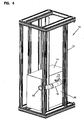
- FIG. 1 illustrates a telecommunications system 10 that includes a telecommunications fixture 12, a telecommunications device 14 mounted within the telecommunications fixture 12, and a heat dissipation device 16 having inventive aspects in accordance with the present disclosure extending between the telecommunications device 14 and the telecommunications fixture 12.
- the telecommunications fixture 12 illustrated in FIG. 1 and the telecommunications device 14 mounted therein are used for describing and illustrating the inventive aspects of the heat dissipation device 16 of the present disclosure and it should be noted that the heat dissipation device 16 can be used in other types of telecommunications environments.
- the telecommunications fixture 12 (e.g., a cabinet or a rack) illustrated in FIG. 1 defines front side 18, a rear side 20, a right side 22, a left side 24, a top side 26, and a bottom side 28.
- the telecommunications fixture 12 includes a number of discrete bays 30 for mounting telecommunications devices 14 in a stacked arrangement therein.
- the telecommunications devices 14 mounted within the fixture may be electronic switching devices.
- a telecommunications fixture such as the fixture 12 shown in FIG. 1 is designed with a generally open architecture formed by rails 32 to direct airflow through the fixture 12.
- telecommunications devices such as the electronic switching device 14 shown in FIG. 1 may be designed to direct airflow from the fronts 34 of the devices 14 to the sides 36 of the devices 14 or from one side of each device to an opposite side of the device 14.
- telecommunications devices such as the device 14 shown in FIG. 1 may include a heat outlet 38 at a side 36 of the device 14.
- each telecommunications fixture 12 housing a high density of telecommunications devices 14 may be designed to have a low temperature region 40 (i.e., aisle) at, for example, the front side 18 of the fixture 12 and a high temperature region 42 at, for example, the rear side 20 of the fixture 12. Please see FIG. 2 .
- a low temperature region 40 i.e., aisle
- any high temperature air generated within the fixture 12 needs to be redirected to the rear side 20 of the fixture 12 and a fixture 12 may include a number of heat outlets 44 at, for example, a rear wall 46 thereof.
- the heat built up at the sides 36 of the devices 14 needs to be directed to the heat outlets 44 at the rear wall 46 of the fixture 12 in order to prevent high temperature air from being pooled between two adjacent switching devices 14 within the fixture 12 and from possibly being sucked into an inlet of an adjacent switching device 14 that may be located near the heat outlet 44 of the first device 14.
- the heat dissipation device 16 of the present disclosure is configured to accommodate a variety of different sized heat outlets 38 of different telecommunications devices 14 that can be mounted within a fixture such as the telecommunications fixture 12 shown in FIGS. 1-4 .
- the heat dissipation device 16 of the present disclosure also provides the flexibility to be able to maintain a heat transfer path between a heat outlet 44 of the telecommunications fixture 12 and a variety of different heat outlet locations of different telecommunications devices 14 that can be mounted within such a telecommunications fixture 12.
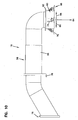
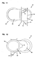
- FIGS. 3-5 a portion of the telecommunications fixture 12 is shown in close-up views to illustrate the heat dissipation device 16 of the present disclose in closer detail, mounted between the heat outlet 38 of the telecommunications device 14 and the heat outlet 44 of the fixture 12. And, in FIGS. 7-12 , the heat dissipation device 16 is shown in isolation, removed from the telecommunications system 10 of FIGS. 1-5 .
- the heat dissipation device 16 defines a conduit 48 that extends between an open first end 50 and an open second end 52.
- the first end 50 is configured to be coupled to the heat outlet 44 of the telecommunications fixture 12.
- the second end 52 is configured to be coupled to the heat outlet 38 of a telecommunications device 14 mounted within the telecommunications fixture 12 such that the heat dissipation device 16 provides a heat transfer path between the heat outlets 38, 44 of the telecommunications device and the telecommunications fixture.
- an outer dimension 54 of the open second end 52 is adjustable in size for corresponding to a variety of different sized heat outlets 38 of different telecommunications devices 14 that can be mounted within the telecommunications fixture 12.
- the conduit 48 in the depicted embodiment, is an enclosed conduit. In other embodiments, the conduit 48 may be only partially enclosed.
- the conduit 48 is defined by a body 56.
- the body 56 defining the conduit 48 is formed from a main body portion 58 coupled to a second end portion 60 by a ring structure 62.
- the ring structure 62 and the second end portion 60 that protrudes from the ring structure 62 are radially expandable so as to provide adjustability to the outer dimension 54 of the second end 52 of the heat dissipation device 16.
- the main body portion 58 and the second end portion 60 of the heat dissipation device 16 are generally tubular.
- the tubular shape defines a generally cylindrical cross-section. It should be noted that the tubular shape may define other types of cross-sections such as square, rectangular, elliptical, etc.
- the open second end 52 defines a cylinder and the outer dimension 54 corresponds to the diameter of that cylinder.
- the conduit 48 of the heat dissipation device 16 defines a longitudinal axis 64 and the outer dimension 54 of the second end 52 is adjustable in a radial direction 66 with respect to the longitudinal axis 64.
- the outer dimension 54 of the open second end 52 is adjustable in size between a first unadjusted dimension and a second adjusted dimension, wherein the second adjusted dimension is between about ,100% to 200%, of the first unadjusted dimension. According to another embodiment, the second adjusted dimension is between about 100% to 150% of the first unadjusted dimension.
- first end 50 can also be adjustable in size to accommodate various telecommunications fixtures 12 or devices 14.
- the second end portion 60 may be manufactured from different types of textiles.
- certain portions of the ring 62 may be manufactured from different types of textiles that allow for those portions of the ring 62 to be expandable and certain portions that require a rigid platform could be manufactured from polymeric materials or different types of metallic materials such as f.i. metal.
- the body 56 (or at least portions of the body 56 such as the main body portion 58) of the heat dissipation device 16 is constructed from a flexible material for adjustability in location between the heat outlet 44 of the telecommunications fixture 12 and the heat outlet 38 of the telecommunications device 14 mounted within the fixture 12.
- the flexible body 56 defining the conduit 48 of the heat dissipation device 16 can maintain a heat transfer path between the heat outlet 44 of a given telecommunications fixture 12 and a variety of different heat outlet locations of different telecommunications devices 14 that can be mounted within the given telecommunications fixture 12.
- the flexible body 56 of the heat dissipation device 16 would accommodate this change in location. Also, if different types of telecommunications devices 14 were mounted within the fixture 12, where the locations of the heat outlets 38 varied relative to their corresponding fixture heat outlets 44, the same type of heat dissipation device 16 could be used for all of the connections.
- the flexible body 56 may be manufactured from different types of textiles, heat resistant rubber, ribbed aluminum or similar flexible materials. It should be noted that in certain embodiments, the flexible body 56 of the heat dissipation device 16 is constructed such that the overall outer dimension of the main body portion 58 remains generally the same while the length of the main body portion 58 may change (such as in an accordion-like structure).
- the heat dissipation device 16 may include an attachment structure 68 adjacent the second end portion 60 of the body 56.
- the attachment structure 68 is provided by suction cups 70 that are configured to provide a vacuum seal with a wall portion 72 of the telecommunications device 14 that surrounds the exhaust port 38.
- the suctions cups 70 are attached to the second end portion 60 of the body 56 via U-shaped links 74. In this manner, the suctions cups 70 radially surround the open second end 52 of the conduit 48 and are able to move radially outwardly with the expanding second end portion 60 of the body 56.
- the same attachment structure 68 of the heat dissipation device 16 is configurable and usable with different telecommunications devices 14.
- the suction cups 70 may be made from heat resistant materials to withstand the heat built up around the exhaust ports 38 of the telecommunications devices 14.
- attachment structures 68 can be used.
- removable adhesives can be used to attach the second end portion 60 of the body 56 to walls of the telecommunications devices 14. Such an embodiment is shown in FIG. 6 .
- the first end 50 of the body 56 of the heat dissipation device 16 may be attached to the heat outlet 44 of the telecommunications fixture 12 by various means known in the art.
- One example attachment structure 76 is shown in FIGS. 7 and 8 . If the heat outlet(s) 44 of the telecommunications fixture 12 is of a predetermined standard size (unlike those of the different types of telecommunications devices 14 that might be mounted therein), then the attachment structure 76 at the first end 50 does not have to provide for the adjustability provided by that of the one at the second end 52. As noted above, if desired, the first end 50 of the heat dissipation device 16 may also provide for the adjustability that is provided by the second end 52.
- the body 56 of the heat dissipation device 16 may also include an additional attachment structure 78 at an intermediate location between the first and second ends 50, 52 for attaching to rails 32 of the telecommunications fixture 12.
Landscapes
- Engineering & Computer Science (AREA)
- Physics & Mathematics (AREA)
- Thermal Sciences (AREA)
- Microelectronics & Electronic Packaging (AREA)
- Aviation & Aerospace Engineering (AREA)
- Geometry (AREA)
- Mechanical Engineering (AREA)
- General Engineering & Computer Science (AREA)
- Cooling Or The Like Of Electrical Apparatus (AREA)
Claims (30)
- Wärmeableitungsvorrichtung (16) für Telekommunikationsvorrichtungen, umfassend:eine Leitung (48), die durch einen flexiblen Körper (56) definiert ist, wobei sich die Leitung (48) zwischen einem offenen ersten Ende (50), das dafür ausgelegt ist, mit einem Wärmeauslass (44) einer Aufnahmevorrichtung für Telekommunikationsausrüstung (12) gekoppelt zu werden, und einem offenen zweiten Ende (52), das dafür ausgelegt ist, mit einem Wärmeauslass (38) einer innerhalb der Aufnahmevorrichtung für Telekommunikationsausrüstung (12) angebrachten Telekommunikationsvorrichtung (14) gekoppelt zu werden, erstreckt, um einen Wärmeübertragungsweg zwischen den Wärmeauslässen (38, 44) bereitzustellen, wobei die erste Leitung eine Längsachse (64) definiert, wobei eine äußere Abmessung (54) des offenen ersten Endes (50) und/oder des offenen zweiten Endes (52) in der Größe verstellbar ist, um einer Vielzahl von Wärmeauslässen (38) unterschiedlicher Größe verschiedener Telekommunikationsvorrichtungen (14), welche innerhalb der Aufnahmevorrichtung für Telekommunikationsausrüstung (12) angebracht werden können, zu entsprechen, derart, dass ein Abschnitt der Leitung (48), der das offene erste Ende (50) und/oder das offene zweite Ende (52) definiert, aus einem Material hergestellt ist, welches in einer radialen Richtung (66) bezüglich der Längsachse (64) dehnbar ist.
- Wärmeableitungsvorrichtung (16) nach Anspruch 1, wobei der flexible Körper (56) rohrförmig ist.
- Wärmeableitungsvorrichtung (16) nach Anspruch 2, wobei der rohrförmige Körper (56) im Wesentlichen zylindrisch ist.
- Wärmeableitungsvorrichtung (16) nach Anspruch 1, wobei die äußere Abmessung (54) ein Durchmesser eines Kreises ist, der durch das offene erste Ende (50) und/oder das offene zweite Ende (52) definiert ist.
- Wärmeableitungsvorrichtung (16) nach Anspruch 1, wobei die äußere Abmessung (54) nur des zweiten Endes (52) in der Größe verstellbar ist.
- Wärmeableitungsvorrichtung (16) nach Anspruch 1, wobei das offene erste Ende (50) und/oder das offene zweite Ende (52) eine Befestigungsstruktur (68) zum Koppeln dieses offenen ersten Endes (50) und/oder offenen zweiten Endes (52) mit einer Telekommunikationsvorrichtung (14) aufweist.
- Wärmeableitungsvorrichtung (16) nach Anspruch 1, wobei die Befestigungsstruktur (68) einen Saugnapf (70) definiert, der dafür ausgelegt ist, eine Vakuumdichtung mit der Telekommunikationsvorrichtung (14) bereitzustellen.
- Wärmeableitungsvorrichtung (16) nach Anspruch 6, wobei die Befestigungsstruktur (68) mehrere Saugnäpfe (70) definiert, die radial um das offene erste Ende (50) und/oder das offene zweite Ende (52) herum angeordnet sind.
- Wärmeableitungsvorrichtung (16) nach Anspruch 1, wobei die äußere Abmessung (54) des offenen ersten Endes (50) und/oder des offenen zweiten Endes (52) in der Größe zwischen einer ersten, nicht verstellten Abmessung und einer zweiten, verstellten Abmessung verstellbar ist, wobei die zweite, verstellte Abmessung zwischen etwa 100 % und 200 % der ersten, nicht verstellten Abmessung liegt.
- Wärmeableitungsvorrichtung (16) nach Anspruch 9, wobei die zweite, verstellte Abmessung zwischen etwa 100 % und 150 % der ersten, nicht verstellten Abmessung liegt.
- Wärmeableitungsvorrichtung (16) für Telekommunikationsvorrichtungen, umfassend:eine umschlossene Leitung (48), die sich zwischen einem offenen ersten Ende (50) und einem offenen zweiten Ende (52) erstreckt und eine Längsachse (64) definiert, wobei das offene erste Ende (50) dafür ausgelegt ist, mit einem Wärmeauslass (44) einer Aufnahmevorrichtung für Telekommunikationsausrüstung (12) gekoppelt zu werden, und das offene zweite Ende (52) dafür ausgelegt ist, mit einem Wärmeauslass (38) einer innerhalb der Aufnahmevorrichtung für Telekommunikationsausrüstung (12) angebrachten Telekommunikationsvorrichtung (14) gekoppelt zu werden, um einen Wärmeübertragungsweg zwischen den Wärmeauslässen (38, 44) der Telekommunikationsvorrichtung (14) und der Aufnahmevorrichtung für Telekommunikationsausrüstung (12) bereitzustellen, wobei eine äußere Abmessung (54) des offenen zweiten Endes (52) in der Größe verstellbar ist, um einer Vielzahl von Wärmeauslässen (38) unterschiedlicher Größe verschiedener Telekommunikationsvorrichtungen (14), welche innerhalb der Aufnahmevorrichtung für Telekommunikationsausrüstung (12) angebracht werden können, zu entsprechen, derart, dass ein Abschnitt der Leitung (48), der das offene zweite Ende (52) definiert, aus einem Material hergestellt ist, welches in einer radialen Richtung (66) bezüglich der Längsachse (64) dehnbar ist, und wobei die umschlossene Leitung (48) durch einen flexiblen Körper (56) definiert ist, um den Wärmeübertragungsweg zwischen dem Wärmeauslass (44) der Aufnahmevorrichtung für Telekommunikationsausrüstung (12) und einer Vielzahl unterschiedlicher Orte der Wärmeauslässe (38) verschiedener Telekommunikationsvorrichtungen (14), welche innerhalb der Aufnahmevorrichtung für Telekommunikationsausrüstung (12) angebracht werden können, aufrechtzuerhalten.
- Wärmeableitungsvorrichtung (16) nach Anspruch 11, wobei der flexible Körper (56) rohrförmig ist.
- Wärmeableitungsvorrichtung (16) nach Anspruch 12, wobei der rohrförmige Körper (56) im Wesentlichen zylindrisch ist.
- Wärmeableitungsvorrichtung (16) nach Anspruch 12, wobei die äußere Abmessung (54) ein Durchmesser eines Kreises ist, der durch das offene zweite Ende (52) definiert ist.
- Wärmeableitungsvorrichtung (16) nach Anspruch 11, wobei das offene zweite Ende (52) eine Befestigungsstruktur (68) aufweist, welche zum Koppeln mit verschiedenen Telekommunikationsvorrichtungen (14) konfigurierbar ist.
- Wärmeableitungsvorrichtung (16) nach Anspruch 15, wobei die Befestigungsstruktur (68) einen Saugnapf (70) definiert, der dafür ausgelegt ist, eine Befestigung mit Vakuumdichtung an verschiedenen Telekommunikationsvorrichtungen (14) bereitzustellen.
- Wärmeableitungsvorrichtung (16) nach Anspruch 16, wobei die Befestigungsstruktur (68) mehrere Saugnäpfe (70) definiert, die radial um das offene zweite Ende (52) herum angeordnet sind.
- Wärmeableitungsvorrichtung (16) nach Anspruch 11, wobei die äußere Abmessung (54) des offenen zweiten Endes (52) in der Größe zwischen einer ersten, nicht verstellten Abmessung und einer zweiten, verstellten Abmessung verstellbar ist, wobei die zweite, verstellte Abmessung zwischen etwa 100 % und 200 % der ersten, nicht verstellten Abmessung liegt.
- Wärmeableitungsvorrichtung (16) nach Anspruch 18, wobei die zweite, verstellte Abmessung zwischen etwa 100 % und 150 % der ersten, nicht verstellten Abmessung liegt.
- Verfahren zum Ermöglichen von Wärmeableitung von verschiedenen Telekommunikationsvorrichtungen (14), die innerhalb einer Aufnahmevorrichtung für Telekommunikationsausrüstung (12) angebracht sind, wobei das Verfahren umfasst:- Bereitstellen einer ersten Leitung (48), die sich zwischen einem offenen ersten Ende (50) und einem offenen zweiten Ende (52) erstreckt, wobei die erste Leitung (48) eine Längsachse (64) definiert;- Koppeln des offenen ersten Endes (50) mit einem ersten Wärmeauslass (44) der Aufnahmevorrichtung für Telekommunikationsausrüstung (12); und- Verstellen einer äußeren Abmessung (54) des offenen zweiten Endes (52) in der Größe, um einer Vielzahl von Wärmeauslässen (38) unterschiedlicher Größe verschiedener Telekommunikationsvorrichtungen (14) zu entsprechen, durch Dehnen oder Verengen eines Abschnitts der ersten Leitung (48) in einer radialen Richtung (66) bezüglich der Längsachse (64), wobei der Abschnitt der ersten Leitung (48), der das offene zweite Ende (52) definiert, aus einem Material hergestellt ist, welches in der radialen Richtung (66) bezüglich der Längsachse (64) dehnbar ist, und Koppeln des offenen zweiten Endes (52) mit einem Wärmeauslass (38) einer innerhalb der Aufnahmevorrichtung für Telekommunikationsausrüstung (12) angebrachten ersten Telekommunikationsvorrichtung (14), um einen Wärmeübertragungsweg zwischen dem Wärmeauslass (38) der ersten Telekommunikationsvorrichtung (14) und dem ersten Wärmeauslass (44) der Aufnahmevorrichtung für Telekommunikationsausrüstung (12) bereitzustellen.
- Verfahren nach Anspruch 20, wobei die äußere Abmessung (54) des offenen zweiten Endes (52) in der Größe verstellbar ist, um einer Vielzahl von Wärmeauslässen (38) unterschiedlicher Größe verschiedener Telekommunikationsvorrichtungen (14), welche innerhalb der Aufnahmevorrichtung für Telekommunikationsausrüstung (12) angebracht werden können, zu entsprechen, und wobei die erste Leitung (48) durch einen flexiblen Körper (56) definiert ist, um den Wärmeübertragungsweg zwischen dem ersten Wärmeauslass (44) der Aufnahmevorrichtung für Telekommunikationsausrüstung (12) und einer Vielzahl unterschiedlicher Orte der Wärmeauslässe (38) verschiedener Telekommunikationsvorrichtungen (14), welche innerhalb der Aufnahmevorrichtung für Telekommunikationsausrüstung (12) angebracht werden können, aufrechtzuerhalten.
- Verfahren nach Anspruch 20, welches ferner das Verstellen der äußeren Abmessung (54) des offenen zweiten Endes (52) in der Größe von einer ersten, nicht verstellten Abmessung zu einer zweiten, verstellten Abmessung umfasst, wobei die zweite, verstellte Abmessung zwischen etwa 100 % und 200 % der ersten, nicht verstellten Abmessung liegt.
- Verfahren nach Anspruch 22, wobei die zweite, verstellte Abmessung zwischen etwa 100 % und 150 % der ersten, nicht verstellten Abmessung liegt.
- Verfahren nach Anspruch 20, welches ferner das Bereitstellen einer zweiten Leitung (48), die der ersten Leitung (48) ähnlich ist, und das Koppeln eines offenen ersten Endes (50) der zweiten Leitung (48) mit einem zweiten Wärmeauslass (44) der Aufnahmevorrichtung für Telekommunikationsausrüstung (12) und das Verstellen einer äußeren Abmessung (54) eines offenen zweiten Endes (52) der zweiten Leitung (48) in der Größe und das Koppeln des offenen zweiten Endes (52) der zweiten Leitung (48) mit einem Wärmeauslass (38) einer innerhalb der Aufnahmevorrichtung für Telekommunikationsausrüstung (12) angebrachten zweiten Telekommunikationsvorrichtung (14), um einen Wärmeübertragungsweg zwischen dem Wärmeauslass (38) der zweiten Telekommunikationsvorrichtung (14) und dem zweiten Wärmeauslass (44) der Aufnahmevorrichtung für Telekommunikationsausrüstung (12) bereitzustellen, umfasst, wobei die zweite Telekommunikationsvorrichtung (14) einen Wärmeauslass (38) mit einer anderen Größe aufweist als die erste Telekommunikationsvorrichtung (14), welche innerhalb der Aufnahmevorrichtung für Telekommunikationsausrüstung (12) angebracht ist.
- Verfahren nach Anspruch 24, wobei die zweite Telekommunikationsvorrichtung (14) einen anderen Ort des Wärmeauslasses (38) bezüglich des restlichen Teils der zweiten Telekommunikationsvorrichtung (14) definiert als die erste Telekommunikationsvorrichtung (14).
- Verfahren nach Anspruch 20, welches ferner das Koppeln des offenen zweiten Endes (52) der ersten Leitung (48) mit dem Wärmeauslass (38) der ersten Telekommunikationsvorrichtung (14) durch Saugwirkung umfasst.
- Verfahren nach Anspruch 20, welches ferner das Koppeln des offenen zweiten Endes (52) der ersten Leitung (48) mit dem Wärmeauslass (38) der ersten Telekommunikationsvorrichtung (14) durch Klebstoff umfasst.
- Telekommunikationssystem (10), umfassend:eine Aufnahmevorrichtung für Telekommunikationsausrüstung (12), die einen Wärmeauslass (44) aufweist;eine Telekommunikationsvorrichtung (14), die innerhalb der Aufnahmevorrichtung für Telekommunikationsausrüstung (12) angebracht ist, wobei die Telekommunikationsvorrichtung (14) einen Wärmeauslass (38) aufweist; undeine Wärmeableitungsvorrichtung (16), die eine Leitung (48) definiert, die sich zwischen einem offenen ersten Ende (50) und einem offenen zweiten Ende (52) erstreckt und eine Längsachse (64) definiert, wobei das offene erste Ende (50) mit dem Wärmeauslass (44) der Aufnahmevorrichtung für Telekommunikationsausrüstung (12) gekoppelt ist und das offene zweite Ende (52) mit dem Wärmeauslass (38) der Telekommunikationsvorrichtung (14) gekoppelt ist, um einen Wärmeübertragungsweg zwischen den Wärmeauslässen (38, 44) der Telekommunikationsvorrichtung (14) und der Aufnahmevorrichtung für Telekommunikationsausrüstung (12) bereitzustellen, wobei eine äußere Abmessung (54) des offenen zweiten Endes (52) in der Größe verstellbar ist, um einer Vielzahl von Wärmeauslässen (38) unterschiedlicher Größe verschiedener Telekommunikationsvorrichtungen (14), welche innerhalb der Aufnahmevorrichtung für Telekommunikationsausrüstung (12) angebracht werden können, zu entsprechen, derart, dass ein Abschnitt der Leitung (48), der das offene zweite Ende (52) definiert, aus einem Material hergestellt ist, welches in einer radialen Richtung (66) bezüglich der Längsachse (64) dehnbar ist, und die Leitung (48) durch einen flexiblen Körper (56) definiert ist.
- Telekommunikationssystem (10) nach Anspruch 28, wobei das offene zweite Ende (52) mit dem Wärmeauslass (38) der Telekommunikationsvorrichtung (14) mit einem Saugnapf (70) gekoppelt ist.
- Telekommunikationssystem (10) nach Anspruch 29, wobei die Wärmeableitungsvorrichtung (16) mehrere Saugnäpfe (70), die radial um das offene zweite Ende (52) herum angeordnet sind, zur Kopplung mit der Telekommunikationsvorrichtung (14) aufweist.
Applications Claiming Priority (3)
| Application Number | Priority Date | Filing Date | Title |
|---|---|---|---|
| US201261621849P | 2012-04-09 | 2012-04-09 | |
| US13/790,654 US20130265720A1 (en) | 2012-04-09 | 2013-03-08 | Heat dissipation device for telecommunications equipment |
| PCT/EP2013/056894 WO2013152969A2 (en) | 2012-04-09 | 2013-04-02 | Heat dissipation device for telecommunications equipment |
Publications (2)
| Publication Number | Publication Date |
|---|---|
| EP2837274A2 EP2837274A2 (de) | 2015-02-18 |
| EP2837274B1 true EP2837274B1 (de) | 2017-06-07 |
Family
ID=48289034
Family Applications (1)
| Application Number | Title | Priority Date | Filing Date |
|---|---|---|---|
| EP13720252.9A Not-in-force EP2837274B1 (de) | 2012-04-09 | 2013-04-02 | Wärmeableitungsvorrichtung für telekommunikationsvorrichtungen |
Country Status (4)
| Country | Link |
|---|---|
| US (1) | US20130265720A1 (de) |
| EP (1) | EP2837274B1 (de) |
| ES (1) | ES2637937T3 (de) |
| WO (1) | WO2013152969A2 (de) |
Families Citing this family (1)
| Publication number | Priority date | Publication date | Assignee | Title |
|---|---|---|---|---|
| US10149411B2 (en) * | 2016-09-09 | 2018-12-04 | Seagate Technology Llc | Rack enclosure cooling systems and related methods |
Family Cites Families (40)
| Publication number | Priority date | Publication date | Assignee | Title |
|---|---|---|---|---|
| US2824575A (en) * | 1954-07-12 | 1958-02-25 | Milprint Inc | Air conditioner attachment |
| US2973016A (en) * | 1958-05-19 | 1961-02-28 | Ernest L Holtsford | Means for securing insulating material about a duct |
| US3500480A (en) * | 1966-07-01 | 1970-03-17 | John H Michal Jr | Urinal attachment for toilet bowl |
| US4249758B1 (en) * | 1978-08-25 | 1993-11-23 | Robert Harris Company, Inc. | Ductwork connecting |
| FR2585918A1 (fr) * | 1985-07-31 | 1987-02-06 | Mcb | Procede et dispositif de ventilation de composants electroniques et d'ensembles ou sous-ensembles de composants electroniques |
| DE3912242A1 (de) * | 1989-04-14 | 1990-10-18 | Gurit Essex Ag | Vorrichtungen zum maschinellen aufbringen von flexiblen, einseitig klebbaren schichtkoerpern auf werkstuecke und verwendung derselben |
| SE469783B (sv) * | 1990-05-29 | 1993-09-13 | Nederman Philip & Co Ab | Anordning för att ansluta en avgasutsugningsslang till avgasröret på ett fordon |
| US5237459A (en) * | 1991-05-06 | 1993-08-17 | Arthur Strauss | Vehicular visual safety device |
| US5358178A (en) * | 1993-08-02 | 1994-10-25 | Crocker Allan L | Vehicle cab heater |
| US5547088A (en) * | 1993-12-28 | 1996-08-20 | Belokin; Paul | Removable display rack assembly |
| IT1273814B (it) * | 1994-02-24 | 1997-07-10 | Ima Spa | Dispositivo per il prelievo, l'apertura e il trasferimento a una linea di confezionamento di involucri ricavati da elementi in foglio |
| US5674123A (en) * | 1995-07-18 | 1997-10-07 | Semifab | Docking and environmental purging system for integrated circuit wafer transport assemblies |
| WO1997033732A1 (en) * | 1996-03-12 | 1997-09-18 | Giuliana Guerrieri | Method and apparatus for gluing frames, mirrors, glass sheets and the like to panels, in particular furniture panels |
| DE19804904C1 (de) * | 1998-02-07 | 1999-11-11 | Loh Kg Rittal Werk | Schaltschrank mit Einrichtungen zum Kühlen der Innenraum-Warmluft |
| US6506111B2 (en) * | 2001-05-16 | 2003-01-14 | Sanmina-Sci Corporation | Cooling airflow distribution device |
| EP1307082A3 (de) * | 2001-10-25 | 2005-11-16 | Alcatel Canada Inc. | Kühlung einer in einem Sicherheitsschrank untergebrachten elektronischen Anlage |
| WO2004043111A2 (en) * | 2002-10-30 | 2004-05-21 | Roark, Sabrina, Nelson | Mountable sound pressure level meter |
| US7112131B2 (en) * | 2003-05-13 | 2006-09-26 | American Power Conversion Corporation | Rack enclosure |
| US6884159B1 (en) * | 2003-06-09 | 2005-04-26 | Robert Ferraud, Jr. | Hose assembly for conduiting and directing air from an air outlet vent of a vehicle to various locations within the vehicle |
| US7295444B1 (en) * | 2003-12-31 | 2007-11-13 | Ncr Corporation | Delivering chilled air to components in a hardware cabinet |
| US20050237716A1 (en) * | 2004-04-21 | 2005-10-27 | International Business Machines Corporation | Air flow system and method for facilitating cooling of stacked electronics components |
| US20060044758A1 (en) * | 2004-08-30 | 2006-03-02 | Power-One As | System and method for managing temperature in an interior-portion of a cabinet |
| US8684800B2 (en) * | 2004-09-28 | 2014-04-01 | Coolcop, Llc | Vehicle air distribution system with universal vent attachment |
| JP4001172B1 (ja) * | 2006-04-17 | 2007-10-31 | ダイキン工業株式会社 | 空気調和装置 |
| US7697285B2 (en) * | 2007-05-17 | 2010-04-13 | Chatsworth Products, Inc. | Electronic equipment enclosure with exhaust air duct and adjustable filler panel assemblies |
| US20090053042A1 (en) * | 2007-08-22 | 2009-02-26 | General Electric Company | Method and apparatus for clearance control of turbine blade tip |
| US7643291B2 (en) * | 2007-08-30 | 2010-01-05 | Afco Systems | Cabinet for electronic equipment |
| US8591066B2 (en) * | 2008-08-19 | 2013-11-26 | Spectronics Corporation | Modular lamp head and assembly for non-destructive testing |
| US20100141105A1 (en) * | 2008-12-04 | 2010-06-10 | Thermocabinet, Llc | Thermal Management Cabinet for Electronic Equipment |
| US8887458B2 (en) * | 2009-10-22 | 2014-11-18 | Specified Technologies Inc. | Self-adjusting firestopping sleeve apparatus with flexibly resilient supplemental constriction means |
| US9494336B2 (en) * | 2010-05-03 | 2016-11-15 | Rite-Hite Holding Corporation | Configurable pliable air ducts |
| US8845403B2 (en) * | 2010-05-18 | 2014-09-30 | International Business Machines Corporation | Individually cooling one or more computers in a rack of computers in a data center |
| US9108486B2 (en) * | 2011-06-15 | 2015-08-18 | Steven Mikel Paquin | Vehicle based climate regulation extension apparatus |
| USD695881S1 (en) * | 2011-07-25 | 2013-12-17 | Gabriel S. Aldana | Beverage temperature control attachment hose |
| US20150046490A1 (en) * | 2011-08-29 | 2015-02-12 | Stephen R. Jacobson | Adjustable hands-free mounting apparatus for tablet pcs emphasizing security and connectibility features |
| US8474778B2 (en) * | 2011-08-29 | 2013-07-02 | Stephen R. Jacobson | Adjustable hands-free mounting apparatus for tablet personal computers |
| US8823611B2 (en) * | 2012-06-07 | 2014-09-02 | Golconda Holdings, Llc | Portable frame-less reversible luminous suction cup display |
| US9046194B2 (en) * | 2013-08-13 | 2015-06-02 | Specifiedtechnologies Inc. | Protective conduit for a structural panel opening |
| USD702056S1 (en) * | 2013-09-24 | 2014-04-08 | Larry Palkiewicz | Fishing rod holder with suction cups |
| US9657962B2 (en) * | 2014-02-27 | 2017-05-23 | Keith Andre Mosley | Tower floor register |
-
2013
- 2013-03-08 US US13/790,654 patent/US20130265720A1/en not_active Abandoned
- 2013-04-02 EP EP13720252.9A patent/EP2837274B1/de not_active Not-in-force
- 2013-04-02 ES ES13720252.9T patent/ES2637937T3/es active Active
- 2013-04-02 WO PCT/EP2013/056894 patent/WO2013152969A2/en not_active Ceased
Also Published As
| Publication number | Publication date |
|---|---|
| WO2013152969A3 (en) | 2013-12-27 |
| US20130265720A1 (en) | 2013-10-10 |
| ES2637937T3 (es) | 2017-10-18 |
| EP2837274A2 (de) | 2015-02-18 |
| WO2013152969A2 (en) | 2013-10-17 |
Similar Documents
| Publication | Publication Date | Title |
|---|---|---|
| CA2865076C (en) | Systems and methods for improved modular laboratory furniture | |
| US10526091B2 (en) | Mobile platform thermal management systems and methods | |
| CN102461357B (zh) | 热通道容纳冷却单元及冷却方法 | |
| US7633754B1 (en) | Air cooling system for an electronics rack | |
| US20170356694A1 (en) | Manufacturing method of heat conducting device | |
| WO2009014892A1 (en) | A/v cooling system and method | |
| EP2837274B1 (de) | Wärmeableitungsvorrichtung für telekommunikationsvorrichtungen | |
| AU2010340138B2 (en) | Microchannel coil manifold system | |
| JP7531636B2 (ja) | データセンタゾーン封じ込めのための空気バリアシステム | |
| AU2010340137B2 (en) | Floating coil heat exchanger | |
| EP2561735B1 (de) | Verfahren und schrank zur temperaturregelung in dem schrank | |
| EP2988424A1 (de) | Kühlsystem für funkeinheit | |
| WO2015088186A1 (ko) | 플렉서블 덕트를 구비한 서버랙의 냉방 제어 장치 | |
| EP2696650B1 (de) | Basisstation | |
| US11592192B2 (en) | Indoor unit of air-conditioning apparatus and air-conditioning apparatus | |
| CN105848436A (zh) | 交换机机柜 | |
| CN120111828A (zh) | 模块化歧管系统 | |
| CN214798515U (zh) | 一种抽屉式开关柜 | |
| US20120279683A1 (en) | Cooling apparatus for communications platforms | |
| CN213282980U (zh) | 一种医用x射线管高效散热装置 | |
| BR102017004128A2 (pt) | Apparatus expansion frame for compressor assembly and method | |
| CN213126753U (zh) | 一种新型网络机柜 | |
| CN215731613U (zh) | 一种晶圆处理装置用箱体及晶圆处理装置 | |
| CN117450578A (zh) | 移动空调进出风管安装结构和移动空调进出风管收纳方法 | |
| CN221165981U (zh) | 一种模块化组合式放液工具 |
Legal Events
| Date | Code | Title | Description |
|---|---|---|---|
| PUAI | Public reference made under article 153(3) epc to a published international application that has entered the european phase |
Free format text: ORIGINAL CODE: 0009012 |
|
| 17P | Request for examination filed |
Effective date: 20141107 |
|
| AK | Designated contracting states |
Kind code of ref document: A2 Designated state(s): AL AT BE BG CH CY CZ DE DK EE ES FI FR GB GR HR HU IE IS IT LI LT LU LV MC MK MT NL NO PL PT RO RS SE SI SK SM TR |
|
| AX | Request for extension of the european patent |
Extension state: BA ME |
|
| DAX | Request for extension of the european patent (deleted) | ||
| GRAP | Despatch of communication of intention to grant a patent |
Free format text: ORIGINAL CODE: EPIDOSNIGR1 |
|
| INTG | Intention to grant announced |
Effective date: 20161109 |
|
| RAP1 | Party data changed (applicant data changed or rights of an application transferred) |
Owner name: COMMSCOPE CONNECTIVITY BELGIUM BVBA |
|
| GRAS | Grant fee paid |
Free format text: ORIGINAL CODE: EPIDOSNIGR3 |
|
| AK | Designated contracting states |
Kind code of ref document: B1 Designated state(s): AL AT BE BG CH CY CZ DE DK EE ES FI FR GB GR HR HU IE IS IT LI LT LU LV MC MK MT NL NO PL PT RO RS SE SI SK SM TR |
|
| REG | Reference to a national code |
Ref country code: GB Ref legal event code: FG4D |
|
| GRAA | (expected) grant |
Free format text: ORIGINAL CODE: 0009210 |
|
| REG | Reference to a national code |
Ref country code: CH Ref legal event code: EP Ref country code: AT Ref legal event code: REF Ref document number: 900099 Country of ref document: AT Kind code of ref document: T Effective date: 20170615 |
|
| REG | Reference to a national code |
Ref country code: IE Ref legal event code: FG4D |
|
| REG | Reference to a national code |
Ref country code: DE Ref legal event code: R096 Ref document number: 602013021964 Country of ref document: DE |
|
| REG | Reference to a national code |
Ref country code: NL Ref legal event code: MP Effective date: 20170607 |
|
| REG | Reference to a national code |
Ref country code: ES Ref legal event code: FG2A Ref document number: 2637937 Country of ref document: ES Kind code of ref document: T3 Effective date: 20171018 |
|
| REG | Reference to a national code |
Ref country code: LT Ref legal event code: MG4D |
|
| PG25 | Lapsed in a contracting state [announced via postgrant information from national office to epo] |
Ref country code: GR Free format text: LAPSE BECAUSE OF FAILURE TO SUBMIT A TRANSLATION OF THE DESCRIPTION OR TO PAY THE FEE WITHIN THE PRESCRIBED TIME-LIMIT Effective date: 20170908 Ref country code: NO Free format text: LAPSE BECAUSE OF FAILURE TO SUBMIT A TRANSLATION OF THE DESCRIPTION OR TO PAY THE FEE WITHIN THE PRESCRIBED TIME-LIMIT Effective date: 20170907 Ref country code: HR Free format text: LAPSE BECAUSE OF FAILURE TO SUBMIT A TRANSLATION OF THE DESCRIPTION OR TO PAY THE FEE WITHIN THE PRESCRIBED TIME-LIMIT Effective date: 20170607 Ref country code: FI Free format text: LAPSE BECAUSE OF FAILURE TO SUBMIT A TRANSLATION OF THE DESCRIPTION OR TO PAY THE FEE WITHIN THE PRESCRIBED TIME-LIMIT Effective date: 20170607 Ref country code: LT Free format text: LAPSE BECAUSE OF FAILURE TO SUBMIT A TRANSLATION OF THE DESCRIPTION OR TO PAY THE FEE WITHIN THE PRESCRIBED TIME-LIMIT Effective date: 20170607 |
|
| REG | Reference to a national code |
Ref country code: AT Ref legal event code: MK05 Ref document number: 900099 Country of ref document: AT Kind code of ref document: T Effective date: 20170607 |
|
| PG25 | Lapsed in a contracting state [announced via postgrant information from national office to epo] |
Ref country code: BG Free format text: LAPSE BECAUSE OF FAILURE TO SUBMIT A TRANSLATION OF THE DESCRIPTION OR TO PAY THE FEE WITHIN THE PRESCRIBED TIME-LIMIT Effective date: 20170907 Ref country code: SE Free format text: LAPSE BECAUSE OF FAILURE TO SUBMIT A TRANSLATION OF THE DESCRIPTION OR TO PAY THE FEE WITHIN THE PRESCRIBED TIME-LIMIT Effective date: 20170607 Ref country code: LV Free format text: LAPSE BECAUSE OF FAILURE TO SUBMIT A TRANSLATION OF THE DESCRIPTION OR TO PAY THE FEE WITHIN THE PRESCRIBED TIME-LIMIT Effective date: 20170607 Ref country code: RS Free format text: LAPSE BECAUSE OF FAILURE TO SUBMIT A TRANSLATION OF THE DESCRIPTION OR TO PAY THE FEE WITHIN THE PRESCRIBED TIME-LIMIT Effective date: 20170607 Ref country code: NL Free format text: LAPSE BECAUSE OF FAILURE TO SUBMIT A TRANSLATION OF THE DESCRIPTION OR TO PAY THE FEE WITHIN THE PRESCRIBED TIME-LIMIT Effective date: 20170607 |
|
| PG25 | Lapsed in a contracting state [announced via postgrant information from national office to epo] |
Ref country code: CZ Free format text: LAPSE BECAUSE OF FAILURE TO SUBMIT A TRANSLATION OF THE DESCRIPTION OR TO PAY THE FEE WITHIN THE PRESCRIBED TIME-LIMIT Effective date: 20170607 Ref country code: RO Free format text: LAPSE BECAUSE OF FAILURE TO SUBMIT A TRANSLATION OF THE DESCRIPTION OR TO PAY THE FEE WITHIN THE PRESCRIBED TIME-LIMIT Effective date: 20170607 Ref country code: SK Free format text: LAPSE BECAUSE OF FAILURE TO SUBMIT A TRANSLATION OF THE DESCRIPTION OR TO PAY THE FEE WITHIN THE PRESCRIBED TIME-LIMIT Effective date: 20170607 Ref country code: AT Free format text: LAPSE BECAUSE OF FAILURE TO SUBMIT A TRANSLATION OF THE DESCRIPTION OR TO PAY THE FEE WITHIN THE PRESCRIBED TIME-LIMIT Effective date: 20170607 Ref country code: EE Free format text: LAPSE BECAUSE OF FAILURE TO SUBMIT A TRANSLATION OF THE DESCRIPTION OR TO PAY THE FEE WITHIN THE PRESCRIBED TIME-LIMIT Effective date: 20170607 |
|
| PG25 | Lapsed in a contracting state [announced via postgrant information from national office to epo] |
Ref country code: PL Free format text: LAPSE BECAUSE OF FAILURE TO SUBMIT A TRANSLATION OF THE DESCRIPTION OR TO PAY THE FEE WITHIN THE PRESCRIBED TIME-LIMIT Effective date: 20170607 Ref country code: SM Free format text: LAPSE BECAUSE OF FAILURE TO SUBMIT A TRANSLATION OF THE DESCRIPTION OR TO PAY THE FEE WITHIN THE PRESCRIBED TIME-LIMIT Effective date: 20170607 Ref country code: IS Free format text: LAPSE BECAUSE OF FAILURE TO SUBMIT A TRANSLATION OF THE DESCRIPTION OR TO PAY THE FEE WITHIN THE PRESCRIBED TIME-LIMIT Effective date: 20171007 |
|
| REG | Reference to a national code |
Ref country code: DE Ref legal event code: R097 Ref document number: 602013021964 Country of ref document: DE |
|
| PLBE | No opposition filed within time limit |
Free format text: ORIGINAL CODE: 0009261 |
|
| STAA | Information on the status of an ep patent application or granted ep patent |
Free format text: STATUS: NO OPPOSITION FILED WITHIN TIME LIMIT |
|
| REG | Reference to a national code |
Ref country code: FR Ref legal event code: PLFP Year of fee payment: 6 |
|
| PG25 | Lapsed in a contracting state [announced via postgrant information from national office to epo] |
Ref country code: DK Free format text: LAPSE BECAUSE OF FAILURE TO SUBMIT A TRANSLATION OF THE DESCRIPTION OR TO PAY THE FEE WITHIN THE PRESCRIBED TIME-LIMIT Effective date: 20170607 |
|
| 26N | No opposition filed |
Effective date: 20180308 |
|
| PG25 | Lapsed in a contracting state [announced via postgrant information from national office to epo] |
Ref country code: SI Free format text: LAPSE BECAUSE OF FAILURE TO SUBMIT A TRANSLATION OF THE DESCRIPTION OR TO PAY THE FEE WITHIN THE PRESCRIBED TIME-LIMIT Effective date: 20170607 |
|
| PGFP | Annual fee paid to national office [announced via postgrant information from national office to epo] |
Ref country code: DE Payment date: 20180427 Year of fee payment: 6 Ref country code: ES Payment date: 20180503 Year of fee payment: 6 |
|
| PGFP | Annual fee paid to national office [announced via postgrant information from national office to epo] |
Ref country code: FR Payment date: 20180425 Year of fee payment: 6 Ref country code: IT Payment date: 20180423 Year of fee payment: 6 |
|
| PGFP | Annual fee paid to national office [announced via postgrant information from national office to epo] |
Ref country code: GB Payment date: 20180427 Year of fee payment: 6 |
|
| PG25 | Lapsed in a contracting state [announced via postgrant information from national office to epo] |
Ref country code: MC Free format text: LAPSE BECAUSE OF FAILURE TO SUBMIT A TRANSLATION OF THE DESCRIPTION OR TO PAY THE FEE WITHIN THE PRESCRIBED TIME-LIMIT Effective date: 20170607 |
|
| REG | Reference to a national code |
Ref country code: CH Ref legal event code: PL |
|
| REG | Reference to a national code |
Ref country code: BE Ref legal event code: MM Effective date: 20180430 |
|
| REG | Reference to a national code |
Ref country code: IE Ref legal event code: MM4A |
|
| PG25 | Lapsed in a contracting state [announced via postgrant information from national office to epo] |
Ref country code: LU Free format text: LAPSE BECAUSE OF NON-PAYMENT OF DUE FEES Effective date: 20180402 |
|
| PG25 | Lapsed in a contracting state [announced via postgrant information from national office to epo] |
Ref country code: LI Free format text: LAPSE BECAUSE OF NON-PAYMENT OF DUE FEES Effective date: 20180430 Ref country code: CH Free format text: LAPSE BECAUSE OF NON-PAYMENT OF DUE FEES Effective date: 20180430 Ref country code: BE Free format text: LAPSE BECAUSE OF NON-PAYMENT OF DUE FEES Effective date: 20180430 |
|
| PG25 | Lapsed in a contracting state [announced via postgrant information from national office to epo] |
Ref country code: IE Free format text: LAPSE BECAUSE OF NON-PAYMENT OF DUE FEES Effective date: 20180402 |
|
| REG | Reference to a national code |
Ref country code: DE Ref legal event code: R119 Ref document number: 602013021964 Country of ref document: DE |
|
| GBPC | Gb: european patent ceased through non-payment of renewal fee |
Effective date: 20190402 |
|
| PG25 | Lapsed in a contracting state [announced via postgrant information from national office to epo] |
Ref country code: DE Free format text: LAPSE BECAUSE OF NON-PAYMENT OF DUE FEES Effective date: 20191101 Ref country code: GB Free format text: LAPSE BECAUSE OF NON-PAYMENT OF DUE FEES Effective date: 20190402 Ref country code: MT Free format text: LAPSE BECAUSE OF NON-PAYMENT OF DUE FEES Effective date: 20180402 |
|
| PG25 | Lapsed in a contracting state [announced via postgrant information from national office to epo] |
Ref country code: FR Free format text: LAPSE BECAUSE OF NON-PAYMENT OF DUE FEES Effective date: 20190430 |
|
| PG25 | Lapsed in a contracting state [announced via postgrant information from national office to epo] |
Ref country code: TR Free format text: LAPSE BECAUSE OF FAILURE TO SUBMIT A TRANSLATION OF THE DESCRIPTION OR TO PAY THE FEE WITHIN THE PRESCRIBED TIME-LIMIT Effective date: 20170607 |
|
| PG25 | Lapsed in a contracting state [announced via postgrant information from national office to epo] |
Ref country code: IT Free format text: LAPSE BECAUSE OF NON-PAYMENT OF DUE FEES Effective date: 20190402 |
|
| PG25 | Lapsed in a contracting state [announced via postgrant information from national office to epo] |
Ref country code: HU Free format text: LAPSE BECAUSE OF FAILURE TO SUBMIT A TRANSLATION OF THE DESCRIPTION OR TO PAY THE FEE WITHIN THE PRESCRIBED TIME-LIMIT; INVALID AB INITIO Effective date: 20130402 Ref country code: PT Free format text: LAPSE BECAUSE OF FAILURE TO SUBMIT A TRANSLATION OF THE DESCRIPTION OR TO PAY THE FEE WITHIN THE PRESCRIBED TIME-LIMIT Effective date: 20170607 |
|
| PG25 | Lapsed in a contracting state [announced via postgrant information from national office to epo] |
Ref country code: MK Free format text: LAPSE BECAUSE OF NON-PAYMENT OF DUE FEES Effective date: 20170607 Ref country code: CY Free format text: LAPSE BECAUSE OF FAILURE TO SUBMIT A TRANSLATION OF THE DESCRIPTION OR TO PAY THE FEE WITHIN THE PRESCRIBED TIME-LIMIT Effective date: 20170607 |
|
| PG25 | Lapsed in a contracting state [announced via postgrant information from national office to epo] |
Ref country code: AL Free format text: LAPSE BECAUSE OF FAILURE TO SUBMIT A TRANSLATION OF THE DESCRIPTION OR TO PAY THE FEE WITHIN THE PRESCRIBED TIME-LIMIT Effective date: 20170607 |
|
| REG | Reference to a national code |
Ref country code: ES Ref legal event code: FD2A Effective date: 20200828 |
|
| PG25 | Lapsed in a contracting state [announced via postgrant information from national office to epo] |
Ref country code: ES Free format text: LAPSE BECAUSE OF NON-PAYMENT OF DUE FEES Effective date: 20190403 |