EP2837012B1 - Verfahren zur prüfung einer trennstelle eines photovoltaik-wechselrichters und photovoltaik-wechselrichter - Google Patents
Verfahren zur prüfung einer trennstelle eines photovoltaik-wechselrichters und photovoltaik-wechselrichter Download PDFInfo
- Publication number
- EP2837012B1 EP2837012B1 EP13731259.1A EP13731259A EP2837012B1 EP 2837012 B1 EP2837012 B1 EP 2837012B1 EP 13731259 A EP13731259 A EP 13731259A EP 2837012 B1 EP2837012 B1 EP 2837012B1
- Authority
- EP
- European Patent Office
- Prior art keywords
- separator
- switching
- voltages
- relays
- photovoltaic inverter
- Prior art date
- Legal status (The legal status is an assumption and is not a legal conclusion. Google has not performed a legal analysis and makes no representation as to the accuracy of the status listed.)
- Active
Links
Images


Classifications
-
- H—ELECTRICITY
- H01—ELECTRIC ELEMENTS
- H01H—ELECTRIC SWITCHES; RELAYS; SELECTORS; EMERGENCY PROTECTIVE DEVICES
- H01H47/00—Circuit arrangements not adapted to a particular application of the relay and designed to obtain desired operating characteristics or to provide energising current
- H01H47/002—Monitoring or fail-safe circuits
- H01H47/004—Monitoring or fail-safe circuits using plural redundant serial connected relay operated contacts in controlled circuit
- H01H47/005—Safety control circuits therefor, e.g. chain of relays mutually monitoring each other
-
- G—PHYSICS
- G01—MEASURING; TESTING
- G01R—MEASURING ELECTRIC VARIABLES; MEASURING MAGNETIC VARIABLES
- G01R31/00—Arrangements for testing electric properties; Arrangements for locating electric faults; Arrangements for electrical testing characterised by what is being tested not provided for elsewhere
- G01R31/40—Testing power supplies
-
- H—ELECTRICITY
- H01—ELECTRIC ELEMENTS
- H01H—ELECTRIC SWITCHES; RELAYS; SELECTORS; EMERGENCY PROTECTIVE DEVICES
- H01H47/00—Circuit arrangements not adapted to a particular application of the relay and designed to obtain desired operating characteristics or to provide energising current
- H01H47/002—Monitoring or fail-safe circuits
-
- H02J3/383—
-
- H—ELECTRICITY
- H02—GENERATION; CONVERSION OR DISTRIBUTION OF ELECTRIC POWER
- H02M—APPARATUS FOR CONVERSION BETWEEN AC AND AC, BETWEEN AC AND DC, OR BETWEEN DC AND DC, AND FOR USE WITH MAINS OR SIMILAR POWER SUPPLY SYSTEMS; CONVERSION OF DC OR AC INPUT POWER INTO SURGE OUTPUT POWER; CONTROL OR REGULATION THEREOF
- H02M7/00—Conversion of AC power input into DC power output; Conversion of DC power input into AC power output
- H02M7/42—Conversion of DC power input into AC power output without possibility of reversal
- H02M7/44—Conversion of DC power input into AC power output without possibility of reversal by static converters
- H02M7/48—Conversion of DC power input into AC power output without possibility of reversal by static converters using discharge tubes with control electrode or semiconductor devices with control electrode
-
- H—ELECTRICITY
- H02—GENERATION; CONVERSION OR DISTRIBUTION OF ELECTRIC POWER
- H02S—GENERATION OF ELECTRIC POWER BY CONVERSION OF INFRARED RADIATION, VISIBLE LIGHT OR ULTRAVIOLET LIGHT, e.g. USING PHOTOVOLTAIC [PV] MODULES
- H02S50/00—Monitoring or testing of PV systems, e.g. load balancing or fault identification
- H02S50/10—Testing of PV devices, e.g. of PV modules or single PV cells
-
- G—PHYSICS
- G01—MEASURING; TESTING
- G01R—MEASURING ELECTRIC VARIABLES; MEASURING MAGNETIC VARIABLES
- G01R31/00—Arrangements for testing electric properties; Arrangements for locating electric faults; Arrangements for electrical testing characterised by what is being tested not provided for elsewhere
- G01R31/327—Testing of circuit interrupters, switches or circuit-breakers
-
- G—PHYSICS
- G01—MEASURING; TESTING
- G01R—MEASURING ELECTRIC VARIABLES; MEASURING MAGNETIC VARIABLES
- G01R31/00—Arrangements for testing electric properties; Arrangements for locating electric faults; Arrangements for electrical testing characterised by what is being tested not provided for elsewhere
- G01R31/40—Testing power supplies
- G01R31/42—AC power supplies
-
- Y—GENERAL TAGGING OF NEW TECHNOLOGICAL DEVELOPMENTS; GENERAL TAGGING OF CROSS-SECTIONAL TECHNOLOGIES SPANNING OVER SEVERAL SECTIONS OF THE IPC; TECHNICAL SUBJECTS COVERED BY FORMER USPC CROSS-REFERENCE ART COLLECTIONS [XRACs] AND DIGESTS
- Y02—TECHNOLOGIES OR APPLICATIONS FOR MITIGATION OR ADAPTATION AGAINST CLIMATE CHANGE
- Y02E—REDUCTION OF GREENHOUSE GAS [GHG] EMISSIONS, RELATED TO ENERGY GENERATION, TRANSMISSION OR DISTRIBUTION
- Y02E10/00—Energy generation through renewable energy sources
- Y02E10/50—Photovoltaic [PV] energy
- Y02E10/56—Power conversion systems, e.g. maximum power point trackers
Definitions
- the invention relates to a method for testing a separation point of a photovoltaic inverter to a power supply network having a plurality of phases and a neutral conductor, wherein a plurality of switching contacts of a plurality of relays of the separation point are driven by the photovoltaic inverter, and the voltages at each phase relative to the neutral conductor respectively before and after the separation point are measured.
- the invention relates to a photovoltaic inverter for converting a DC voltage into an AC voltage having a plurality of phases and a neutral conductor and for feeding the AC voltage in a power supply network with a plurality of phases and a neutral conductor, with a separation point of several relays with multiple switching contacts for electrical isolation to the Phases and the neutral conductor of the power supply network, wherein means are provided for measuring the voltages of the phases relative to the neutral conductor before and after the separation point.
- an arrangement of one relay pair per phase is used as a separation point between the photovoltaic inverter and the power grid to achieve a secure separation from the power grid.
- compliance with relevant standards and regulations is required.
- E DIN VDE 0128 a release point of two independent devices for network monitoring with associated switches in series prescribed.
- the US 2010/0226160 A1 shows a method for testing a separation point of a photovoltaic inverter of the subject type, wherein the voltages are measured at each phase relative to the neutral conductor respectively before and after the separation point. It is not possible to infer the functionality of the separation point of the photovoltaic inverter and an exact determination of any defective switching contact the separation point.
- the object of the present invention is to provide an above-mentioned method and a photovoltaic inverter, with which the functionality of the separation point can be checked quickly and easily without additional component complexity.
- the separation point should also be as space-saving and cheap as possible.
- This object is achieved in procedural respects by the fact that in the separation point at least one phase before the separation point and at least one phase is crossed after the separation point, the switching contacts of the separation point are gradually switched and tested according to a switching pattern, the switching pattern by stepwise change of the switching contacts Separation point is realized by a switching state to another switching state and each switching state is assigned a measurement result according to a scoring table, and in each switching state of the switching pattern, the functionality of the switching contacts of the separation point is derived by at each switching state, the voltages at least one phase relative to the neutral respectively measured before and after the separation point and compared with the measurement results of the evaluation table. It is achieved in an advantageous manner to check the functionality of each switch contact - even with two- and multi-pole relay -.
- the separation point does not necessarily have to be integrated in the photovoltaic inverter, as a result of which the size of the photovoltaic inverter does not have to be changed. It may, for example, a separation point in the photovoltaic inverter and a second separation point be arranged externally. In this case, a corresponding communication between the separation points, so that the voltages can be transmitted. Accordingly, the separation points are also crossed out.
- the switching pattern is realized by stepwise change of the switching contacts of the separation point of a switching state to another switching state, in each of the switching states or the change of the switching states each of the functionality of the individual switching contacts of the separation point is derived. Each time the switching state of the switching contacts of the separation point in the form of opening or closing of the switching contacts, the functionality of the switching contacts of the separation point is derived.
- the voltages required for the voltage measurement can be provided by the power grid or by the photovoltaic inverter.
- the measured voltages before and after the separation point are processed by two independent controllers, which controllers are interconnected via a data bus.
- the object of the invention is also achieved by an above-mentioned photovoltaic inverter, wherein the separation point consists of four relays, each with at least one switching contact, wherein for each connection of the phases and the neutral conductor two switching contacts of two mutually independently switchable relays are connected in series , and in the separation point at least one phase before the separation point and at least one phase after the separation point is crossed off, and two independent controllers are provided for processing the measured voltages of the phases with respect to the neutral conductor before and after the separation point, which controllers communicate with each other via a data bus are connected, and the controllers are designed to derive the functionality of the switch contacts in each switching state via the comparison of the measured voltages with measured values assigned in an evaluation table.
- a controller having two relays on the input side of the disconnection point is connected for controlling the switching contacts of these relays and for processing the voltages measured before the disconnection, and the second independent controller having two relays on the output side Separation point connected to the control of the switching contacts of these relays and for processing the voltages measured after the separation point.
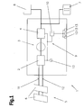
- FIG. 1 a structure of a known photovoltaic inverter 1, in detail of an RF inverter, shown. Since the individual components or assemblies and functions of photovoltaic inverters 1 are already known from the prior art, they will not be discussed in detail below.
- the photovoltaic inverter 1 has at least one input DC-DC converter 2, an intermediate circuit 3 and an output DC-AC converter 4.
- a power source 5 or a power generator is connected, which are preferably formed from one or more parallel and / or series-connected solar modules 6.
- the photovoltaic inverter 1 and the solar modules 6 are also referred to as a photovoltaic system or as a PV system.
- the output of the photovoltaic inverter 1 or of the output DC-AC converter 4 can be connected to a power supply network 7, such as a public or private AC network or a multi-phase network, and / or with at least one electrical load 8, which is a load be connected.
- a consumer 8 is formed by an engine, refrigerator, radio, and so on. Likewise, the consumer 8 also a Represent domestic care.
- the individual components of the photovoltaic inverter 1, such as the input DC-DC converter 2, etc., may be connected to a control device 10 via a data bus 9.
- such a photovoltaic inverter 1 serves as a so-called grid-connected photovoltaic inverter 1, whose energy management is then optimized to feed as much energy into the power grid 7.
- the consumers 8 are supplied via the supply network 7.
- a plurality of parallel connected photovoltaic inverters 1 can be used. As a result, more energy for operating the consumer 8 can be provided.
- This energy is supplied by the power source 5 in the form of a DC voltage, which is connected via two connecting lines 11, 12 with the photovoltaic inverter 1.
- the controller 10 or the controller of the photovoltaic inverter 1 is formed for example by a microprocessor, microcontroller or computer. Via the control device 10, a corresponding control of the individual components of the photovoltaic inverter 1, such as the input DC-DC converter 2 or the output DC-AC converter 4, in particular the switching elements arranged therein, are made. In the control device 10 for this purpose, the individual control or control processes are stored by appropriate software programs and / or data or characteristics.
- control elements 13 are connected to the control device 10, by means of which the user can, for example, configure the photovoltaic inverter 1 and / or display operating states or parameters (for example by means of light-emitting diodes) and set them.
- the controls 13 are connected for example via the data bus 9 or directly to the control device 10.
- Such controls 13 are arranged for example on a front of the photovoltaic inverter 1, so that an operation from the outside is possible.
- the operating elements 13 can also be arranged directly on assemblies and / or modules within the photovoltaic inverter 1.
- the separation point 14 between the photovoltaic inverter 1 and the power supply network 7 has four two-pole relays 18, 19, 20 and 21. Each of these relays 18-21 has a control coil and two switching contacts connected thereto.
- Fig. 2 results for each line between the photovoltaic inverter 1 and the supply network 7, a series circuit of two, each independently controllable switch contacts.
- the terminal 22 of the phase L1 on the side of the photovoltaic inverter 1 is connected via the first contacts of the relays 18 and 20 to the terminal 26 of the phase L1 of the power supply network 7.
- the terminal 23 of the phase L2 on the side of the photovoltaic inverter 1 is connected via the first contact of the relay 19 and the second contact of the relay 20 to the terminal 27 of the phase L2 of the supply network 7.
- the terminal 24 of the phase L3 on the side of the photovoltaic inverter 1 is connected via the second contact of the relay 18 and the first contact of the relay 21 to the terminal 28 of the phase L3 of the power supply network 7.
- the terminal 25 of the neutral conductor on the side of the photovoltaic inverter 1 is connected via the second contact of the relay 19 and the second contact of the relay 21 to the terminal 29 of the neutral conductor of the power supply network 7.
- the voltage measurement takes place, for example, with the aid of a differential amplifier, which is the measurement processing for the measuring unit, which can be implemented, for example, as a microcontroller with analog / digital converter, the measurement of the voltages at the individual phases L1, L2, L3 with respect to the neutral conductor N performs.
- a differential amplifier which is the measurement processing for the measuring unit, which can be implemented, for example, as a microcontroller with analog / digital converter
- the individual switching contacts of the separation point 14 via measurement of the voltages 30, 31 and 32 between the phases L1, L2 and L3 and the neutral conductor N before the separation point 14 and measuring the voltages 33, 34 and 35 between the phases L1, L2 and L3 and the neutral conductor N after the separation point 14 and a comparison of these voltages 30-35 are checked.
- the voltages are provided either via the power supply network 7, or in the case of an island inverter from the photovoltaic inverter 1.
- the measurement voltage thus corresponds to the phase voltage.
- the measurements of the voltages 30, 31, 32 occur before the separation point 14 at the respective terminals 22, 23, 24 of the phases L1, L2, L3 opposite the terminal 25 of the neutral conductor N on the side of the photovoltaic inverter 1.
- the measurements of the voltages 33, 34, 35 take place after the separation point 14 at the respective terminals 26, 27, 28 of the phases L1, L2, L3 with respect to the terminal 29 of the neutral conductor N on the side of the power supply network 7.
- the measured voltages 30, 31, 32 and 33, 34, 35 before and after the separation point 14 are processed by two independent controllers 15 and 16, which can communicate with each other via a data bus 17.
- controllers 15, 16 also two of the four relays 18-21 are controlled.
- the inventive method for testing the individual switching contacts of the relay 18-21 is realized for example by an appropriate software.
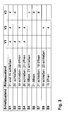
- the test of the individual switching contacts of the separation point 14 for example, in the table according to Fig. 3 shown switching pattern in combination with the evaluation table shown therein. If the corresponding measurement result according to the evaluation table is fulfilled in the respective switching state, the Functionality of the switching contacts of the separation point 14 given.
- This comparison is carried out by the controllers 15, 16, the voltages of the same phase L1, L2, L3 being compared with one another in each case. Accordingly, there is always a voltage value at one side of the separation point 14. On which side the voltage is applied depends on whether the voltage for the measurement from the power grid 7 or the photovoltaic inverter 1 is provided. On the other side of the separation point 14, a voltage value is measured only when the corresponding relay 18-21 are connected. By this measuring method or test method can be determined whether all the switching contacts of the separation point 14 can be closed and opened again. In addition to the switching states S1-S9 described below, which are relevant for the test of the individual switching contacts of the relays 18-21, five further switching states which occur during the change of the switching states S1-S9 are required.
- the relay 20 is closed, all other relays 18, 19, 21 remain in the previous switching state.
- this switching state is now checked whether the voltages 30 and 33 are unequal, since relay 18 must be open. If this is not true, then the first switching contact of the relay 18 is defective. Furthermore, it must be checked whether the voltages 32 and 35 are unequal. If this is not true, then the second switching contact of the relay 18 is defective. In addition, it is checked whether the voltages 31 and 34 are the same. If this is not the case, the second switching contact of the relay 20 has not closed correctly.
- the relay 20 In order to change to the next switching state S4, the relay 20 is closed and the relay 21 is opened. In this state, the voltage 30 must be unequal to the voltage 33 and the voltage 31 unequal to the voltage 34 for a correct function of the switching contacts of the separation point 14. If one of the two conditions is not met, the second switching contact of the relay 21 sticks. This statement can therefore be made because of the second switching contact of the relay 21, the voltage at terminal 29 or terminal 25 is switched and has already been successfully checked in the previous switching states that the switching contacts of the relays 20 and 21 can be closed at least correctly.
- relay 20 is opened and relay 21 is closed.
- the voltages 32 and 35 must be equal. If this is not the case, the first switching contact of relay 21 could not be closed correctly.
- the remaining voltages do not have to be compared in this switching state S5, as this means that no additional statements can be made about the functionality of the switching contacts.
- relay 21 is opened. In this switching state, it is checked whether the voltages 32 and 35 are unequal. If these two voltages 32 and 35 are the same, it can be concluded that an adhesive first switching contact of relay 21, since at an opening of this switch contact, the voltages would have to be unequal. From the remaining voltage measurements no further relevant information can be obtained in this switching state S6.
- the relay 21 In order to change to the next switching state S7, the relay 21 is closed and the relay 19 is opened. In this switching state, it is checked whether the voltages 32 and 35 are unequal. If this is not the case, then the second switching contact of relay 19 sticks, because through this for one of the two measurements (which depends on which side of the separation point 14 is supplied with the voltage), the voltages at the terminals 25 or 29 would have to be switched off , The correct closing of the second switching contact of the relay 19 and the second switching contact of the relay 21 has already been checked by ensuring the equality of the voltage 32 and 35 in the switching state S5. The other voltages are relevant in this switching state S5 for no further test.
- the relays 19 and 20 are closed.
- this switching state is checked whether the voltages 31 and 34 are the same. If this is not the case, then it can be concluded that the first switching contact of the relay 19 has not been closed correctly. This statement can be made because the second switching contact of the relay 21 in the switching state S4 and the second switching contact of the relay 20 has already been tested in the switching state S3 and thus sticking to the condition of the first switching contact of the relay 19 in case of non-compliance. The other voltages bring in this switching state S8 no further information.
- the relay 19 is opened.
- the voltage 31 must be unequal to the voltage 34. If this is not true, then the first switching contact of the relay sticks 19. This statement can be made because the correct function of the second switching contact of the relay 19 already in the switching state S8 and the functionality of the first and second switching contacts of the relays 18, 20 and 21 in the previous switching states has been checked. The other voltages are relevant in this switching state S9 for no further information.
- the relays 18 to 21 of the separation point 14 are switched over in accordance with each switching state S1-S9, the switching state being retained by the preceding switching state, if this is not changed with the current switching state.
- the voltages 30-35 of all phases L1-L3 are always measured in each switching state, with the voltages according to the evaluation table having to match for testing the functionality of the switching contacts.
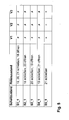
- the separation point 14 can also be realized with two three-pole relays 18 and 20 and two single-pole relays 19 and 21, as in FIG Fig. 4 shown.
- the check of the separation point 14 on adhesive switch contacts is also done here by comparing the measured voltages 30, 31, 32 and 33, 34, 35 before and after the separation point 14.
- a switching pattern is run through, its states in the table according to Fig. 5 are shown.
- the change from one switching state to the next takes place by stepwise switching of at least one of the relays 18-21, wherein the driving to the circuit can be performed by the controllers 15, 16.
- This variant of the test procedure starts in the initial state S1_1.
- the relays 19, 20 and 21 are closed and the relay 18 is opened.
- the voltages 30 and 33 must be unequal. If this is not the case, then the first switching contact of the relay 18 sticks.
- the voltages 31 and 34 must be unequal. If this is not the case, then sticks the third switching contact of the relay 18.
- the voltages must be 32 and 35 unequal. If this is not the case, then the second switching contact of the relay 18 sticks.
- the relay 18 In order to change to the next switching state S2_1, the relay 18 is closed and the relay 20 is opened. In this switching state, the voltages 30 and 33 must be unequal. If this is not the case, then the first switching contact of the relay 20 sticks. In addition, the voltages 31 and 34 must be unequal. If this is not the case, then the second switching contact of the relay 20 sticks. Furthermore, the voltages 32 and 35 must be unequal. If this is not the case, the third switch contact of the relay 20 sticks. These statements can be made because the connections 22-24 must be interrupted before the disconnection point 14 from the connections 26-28 to the disconnection point via the relay 20.
- the relay 20 is closed and the relay 19 is opened.
- the voltages 30 and 33 must be unequal. If this is not the case, then the first switching contact of the relay 19 sticks. In addition, the voltages 31 and 34 and the voltages 32 and 35 must be unequal.
Landscapes
- Physics & Mathematics (AREA)
- General Physics & Mathematics (AREA)
- Engineering & Computer Science (AREA)
- Power Engineering (AREA)
- Inverter Devices (AREA)
- Keying Circuit Devices (AREA)
- Relay Circuits (AREA)
- Supply And Distribution Of Alternating Current (AREA)
- Photovoltaic Devices (AREA)
Applications Claiming Priority (2)
| Application Number | Priority Date | Filing Date | Title |
|---|---|---|---|
| ATA50232/2012A AT512983B1 (de) | 2012-06-13 | 2012-06-13 | Verfahren zur Prüfung einer Trennstelle eines Photovoltaik-Wechselrichters und Photovoltaik-Wechselrichter |
| PCT/AT2013/050118 WO2013185160A1 (de) | 2012-06-13 | 2013-06-11 | Verfahren zur prüfung einer trennstelle eines photovoltaik-wechselrichters und photovoltaik-wechselrichter |
Publications (2)
| Publication Number | Publication Date |
|---|---|
| EP2837012A1 EP2837012A1 (de) | 2015-02-18 |
| EP2837012B1 true EP2837012B1 (de) | 2015-11-04 |
Family
ID=48698829
Family Applications (1)
| Application Number | Title | Priority Date | Filing Date |
|---|---|---|---|
| EP13731259.1A Active EP2837012B1 (de) | 2012-06-13 | 2013-06-11 | Verfahren zur prüfung einer trennstelle eines photovoltaik-wechselrichters und photovoltaik-wechselrichter |
Country Status (7)
| Country | Link |
|---|---|
| US (1) | US9494659B2 (https=) |
| EP (1) | EP2837012B1 (https=) |
| JP (1) | JP5926857B2 (https=) |
| CN (1) | CN104364869B (https=) |
| AT (1) | AT512983B1 (https=) |
| IN (1) | IN2014DN07526A (https=) |
| WO (1) | WO2013185160A1 (https=) |
Cited By (1)
| Publication number | Priority date | Publication date | Assignee | Title |
|---|---|---|---|---|
| EP3633817A1 (de) | 2018-10-03 | 2020-04-08 | FRONIUS INTERNATIONAL GmbH | Verfahren zur prüfung einer trennstelle eines photovoltaik-wechselrichters und ein solcher photovoltaik-wechselrichter |
Families Citing this family (6)
| Publication number | Priority date | Publication date | Assignee | Title |
|---|---|---|---|---|
| US10424935B2 (en) | 2009-09-15 | 2019-09-24 | Rajiv Kumar Varma | Multivariable modulator controller for power generation facility |
| FR3074914B1 (fr) | 2017-12-07 | 2019-11-29 | Socomec | Procede de detection de l'etat d'un appareil de protection electrique dans une installation electrique et dispositif de detection mettant en oeuvre ledit procede |
| DE102019204385A1 (de) * | 2019-03-28 | 2020-10-01 | Siemens Aktiengesellschaft | Überwachungsanordnung und Verfahren zur Überwachung |
| CN112433149B (zh) * | 2020-11-25 | 2023-08-15 | 浙江艾罗网络能源技术股份有限公司 | 一种单相光伏并网逆变器继电器失效检测装置及方法 |
| CN113867200A (zh) * | 2021-09-18 | 2021-12-31 | 周明祥 | 一种方向识别模块 |
| CN114300307B (zh) * | 2021-11-30 | 2024-01-02 | 厦门科华数能科技有限公司 | 一种储能逆变器中旁路继电器单元的粘死检测方法和储能逆变器 |
Family Cites Families (17)
| Publication number | Priority date | Publication date | Assignee | Title |
|---|---|---|---|---|
| JP3979278B2 (ja) * | 2002-11-29 | 2007-09-19 | 松下電工株式会社 | 系統連系インバータ装置 |
| US7256566B2 (en) * | 2003-05-02 | 2007-08-14 | Ballard Power Systems Corporation | Method and apparatus for determining a maximum power point of photovoltaic cells |
| WO2007086413A1 (ja) * | 2006-01-27 | 2007-08-02 | Sansha Electric Manufacturing Co., Ltd. | 太陽光発電インバータ |
| US8023297B2 (en) * | 2008-06-27 | 2011-09-20 | General Electric Company | High efficiency photovoltaic inverter |
| DE102008048841B8 (de) * | 2008-09-25 | 2010-06-10 | Fraunhofer-Gesellschaft zur Förderung der angewandten Forschung e.V. | Trennschaltung für Wechselrichter |
| DK2228895T3 (da) * | 2009-03-09 | 2013-04-08 | Sma Solar Technology Ag | Vekselretter med netværksgrænseflade |
| JP2010226843A (ja) * | 2009-03-23 | 2010-10-07 | Honda Motor Co Ltd | 単相−n相変換装置 |
| EP2296244B1 (de) * | 2009-08-06 | 2015-02-18 | SMA Solar Technology AG | Verfahren und Schaltungsanordnung zum Verbinden mindestens eines Strings einer Photovoltaikanlage mit einem Wechselrichter |
| DE202009018199U1 (de) * | 2009-10-01 | 2011-06-09 | changetec GmbH, 71691 | Freischaltsteuergerät |
| US8462518B2 (en) * | 2009-10-12 | 2013-06-11 | Solarbridge Technologies, Inc. | Power inverter docking system for photovoltaic modules |
| EP2509183A4 (en) * | 2009-11-30 | 2016-01-27 | Panasonic Ip Man Co Ltd | POWER SUPPLY UNIT |
| US8836162B2 (en) * | 2010-02-26 | 2014-09-16 | Ziehl-Abegg Ag | Inverter for photovoltaic systems |
| JP5605548B2 (ja) * | 2010-04-12 | 2014-10-15 | 富士電機株式会社 | 系統連系装置 |
| EP2671315A2 (en) * | 2010-06-04 | 2013-12-11 | ABB Inc. | Detection of welded switch contacts in a line converter system |
| US9121913B2 (en) * | 2011-03-21 | 2015-09-01 | Deere & Company | System for detecting a failure associated with an inverter or associated machine |
| JP2012235659A (ja) * | 2011-05-09 | 2012-11-29 | Denso Corp | 回転機の制御装置 |
| US20130222951A1 (en) * | 2012-02-28 | 2013-08-29 | General Electric Company | Fault protection circuit for photovoltaic power system |
-
2012
- 2012-06-13 AT ATA50232/2012A patent/AT512983B1/de not_active IP Right Cessation
-
2013
- 2013-06-11 CN CN201380029489.9A patent/CN104364869B/zh active Active
- 2013-06-11 JP JP2015507298A patent/JP5926857B2/ja active Active
- 2013-06-11 US US14/395,184 patent/US9494659B2/en active Active
- 2013-06-11 WO PCT/AT2013/050118 patent/WO2013185160A1/de not_active Ceased
- 2013-06-11 IN IN7526DEN2014 patent/IN2014DN07526A/en unknown
- 2013-06-11 EP EP13731259.1A patent/EP2837012B1/de active Active
Cited By (2)
| Publication number | Priority date | Publication date | Assignee | Title |
|---|---|---|---|---|
| EP3633817A1 (de) | 2018-10-03 | 2020-04-08 | FRONIUS INTERNATIONAL GmbH | Verfahren zur prüfung einer trennstelle eines photovoltaik-wechselrichters und ein solcher photovoltaik-wechselrichter |
| US11125833B1 (en) | 2018-10-03 | 2021-09-21 | Fronius International Gmbh | Method for testing a disconnection point of a photovoltaic inverter, and a photovoltaic inverter of this type |
Also Published As
| Publication number | Publication date |
|---|---|
| AT512983B1 (de) | 2014-06-15 |
| CN104364869B (zh) | 2017-03-22 |
| JP5926857B2 (ja) | 2016-05-25 |
| EP2837012A1 (de) | 2015-02-18 |
| CN104364869A (zh) | 2015-02-18 |
| US9494659B2 (en) | 2016-11-15 |
| AT512983A1 (de) | 2013-12-15 |
| IN2014DN07526A (https=) | 2015-04-24 |
| US20150091604A1 (en) | 2015-04-02 |
| WO2013185160A1 (de) | 2013-12-19 |
| JP2015519688A (ja) | 2015-07-09 |
Similar Documents
| Publication | Publication Date | Title |
|---|---|---|
| EP2837012B1 (de) | Verfahren zur prüfung einer trennstelle eines photovoltaik-wechselrichters und photovoltaik-wechselrichter | |
| DE102012104560B4 (de) | Erkennung der Stringkonfiguration für einen Multistring-Wechselrichter | |
| EP2927044B1 (de) | Verfahren zum Betreiben paralleler Hilfsbetriebeumrichter in einem Schienenfahrzeug | |
| EP3391519B1 (de) | Wechselrichter und verfahren zum betreiben eines wechselrichters | |
| EP3345294B1 (de) | Verfahren zum betrieb eines wechselrichters und wechselrichter | |
| DE102012104315B4 (de) | Verfahren zum sequenziellen Trennen/Verbinden von elektrischen Stromquellen von/mit einer gemeinsamen Last | |
| DE102015102468B3 (de) | Netzersatzanlage und Erdungseinrichtung für eine Netzersatzanlage | |
| DE102014202426B4 (de) | Verfahren zur Prüfung einer Trennstelle eines Photovoltaik-Wechselrichters und Photovoltaik-Wechselrichter | |
| EP3837746B1 (de) | Elektrische ac/dc-umwandlungs-anordnung | |
| EP2608375B1 (de) | Schaltungsanordnung mit einem wechselrichter und verfahren zur funktionsprüfung von elektromechanischen schaltern | |
| DE102011054002A1 (de) | Dezentrale Energieerzeugungsanlage mit Einrichtung und Verfahren zur Inselnetzerkennung | |
| DE102012102766B3 (de) | Netzersatzanlage und Erdungseinrichtung für eine Netzersatzanlage | |
| DE102012215166B4 (de) | Schaltgerät für einen Einphasenmotor und einen Drehstrommotor | |
| DE102012100673A1 (de) | Vorrichtung zur elektrischen Energieeinspeisung aus einer dezentralen Eigenerzeugeranlage in ein Stromnetz | |
| EP3824524B1 (de) | Verfahren zur prüfung einer trennstelle eines photovoltaik-wechselrichters und ein solcher photovoltaik-wechselrichter | |
| EP3275067B1 (de) | Verfahren zum verbinden einer energieerzeugungsanlage mit einem mittelspannungsnetz und energieerzeugungsanlage | |
| DE102011018229B4 (de) | Schaltungsanordnung und Verfahren zur Potentialtrennung eines elektrischen Geräts vom Netz | |
| DE102012011275A1 (de) | Zählerprüfeinrichtung und Zählerprüfverfahren zum Prüfen eines Elektrizitätszählers | |
| EP3929595A1 (de) | Energiemessklemme beziehungsweise messschaltung einer energiemessklemme | |
| DE102012018411A1 (de) | Schaltungsanordnung, sowie Pegelwandler und Vergleicherschaltung für die Schaltungsanordnung | |
| WO2022096393A1 (de) | Selektive schnellabschaltung einer ladevorrichtung | |
| WO2019076405A1 (de) | Batteriesystem, lokales stromnetz und trennschalter | |
| DE102013112362A1 (de) | Photovoltaikanlage sowie Betriebsverfahren und Wechselrichter für eine Photovoltaikanlage |
Legal Events
| Date | Code | Title | Description |
|---|---|---|---|
| PUAI | Public reference made under article 153(3) epc to a published international application that has entered the european phase |
Free format text: ORIGINAL CODE: 0009012 |
|
| 17P | Request for examination filed |
Effective date: 20140829 |
|
| AK | Designated contracting states |
Kind code of ref document: A1 Designated state(s): AL AT BE BG CH CY CZ DE DK EE ES FI FR GB GR HR HU IE IS IT LI LT LU LV MC MK MT NL NO PL PT RO RS SE SI SK SM TR |
|
| AX | Request for extension of the european patent |
Extension state: BA ME |
|
| GRAP | Despatch of communication of intention to grant a patent |
Free format text: ORIGINAL CODE: EPIDOSNIGR1 |
|
| DAX | Request for extension of the european patent (deleted) | ||
| INTG | Intention to grant announced |
Effective date: 20150625 |
|
| RIN1 | Information on inventor provided before grant (corrected) |
Inventor name: BLOECHL, STEFAN Inventor name: DANMAYR, JOACHIM |
|
| GRAS | Grant fee paid |
Free format text: ORIGINAL CODE: EPIDOSNIGR3 |
|
| GRAA | (expected) grant |
Free format text: ORIGINAL CODE: 0009210 |
|
| AK | Designated contracting states |
Kind code of ref document: B1 Designated state(s): AL AT BE BG CH CY CZ DE DK EE ES FI FR GB GR HR HU IE IS IT LI LT LU LV MC MK MT NL NO PL PT RO RS SE SI SK SM TR |
|
| REG | Reference to a national code |
Ref country code: GB Ref legal event code: FG4D Free format text: NOT ENGLISH |
|
| REG | Reference to a national code |
Ref country code: CH Ref legal event code: EP |
|
| REG | Reference to a national code |
Ref country code: AT Ref legal event code: REF Ref document number: 759713 Country of ref document: AT Kind code of ref document: T Effective date: 20151115 |
|
| REG | Reference to a national code |
Ref country code: IE Ref legal event code: FG4D Free format text: LANGUAGE OF EP DOCUMENT: GERMAN |
|
| REG | Reference to a national code |
Ref country code: DE Ref legal event code: R096 Ref document number: 502013001454 Country of ref document: DE |
|
| REG | Reference to a national code |
Ref country code: NL Ref legal event code: MP Effective date: 20151104 |
|
| REG | Reference to a national code |
Ref country code: LT Ref legal event code: MG4D |
|
| PG25 | Lapsed in a contracting state [announced via postgrant information from national office to epo] |
Ref country code: NO Free format text: LAPSE BECAUSE OF FAILURE TO SUBMIT A TRANSLATION OF THE DESCRIPTION OR TO PAY THE FEE WITHIN THE PRESCRIBED TIME-LIMIT Effective date: 20160204 Ref country code: LT Free format text: LAPSE BECAUSE OF FAILURE TO SUBMIT A TRANSLATION OF THE DESCRIPTION OR TO PAY THE FEE WITHIN THE PRESCRIBED TIME-LIMIT Effective date: 20151104 Ref country code: NL Free format text: LAPSE BECAUSE OF FAILURE TO SUBMIT A TRANSLATION OF THE DESCRIPTION OR TO PAY THE FEE WITHIN THE PRESCRIBED TIME-LIMIT Effective date: 20151104 Ref country code: IS Free format text: LAPSE BECAUSE OF FAILURE TO SUBMIT A TRANSLATION OF THE DESCRIPTION OR TO PAY THE FEE WITHIN THE PRESCRIBED TIME-LIMIT Effective date: 20160304 Ref country code: HR Free format text: LAPSE BECAUSE OF FAILURE TO SUBMIT A TRANSLATION OF THE DESCRIPTION OR TO PAY THE FEE WITHIN THE PRESCRIBED TIME-LIMIT Effective date: 20151104 Ref country code: ES Free format text: LAPSE BECAUSE OF FAILURE TO SUBMIT A TRANSLATION OF THE DESCRIPTION OR TO PAY THE FEE WITHIN THE PRESCRIBED TIME-LIMIT Effective date: 20151104 |
|
| PG25 | Lapsed in a contracting state [announced via postgrant information from national office to epo] |
Ref country code: FI Free format text: LAPSE BECAUSE OF FAILURE TO SUBMIT A TRANSLATION OF THE DESCRIPTION OR TO PAY THE FEE WITHIN THE PRESCRIBED TIME-LIMIT Effective date: 20151104 Ref country code: LV Free format text: LAPSE BECAUSE OF FAILURE TO SUBMIT A TRANSLATION OF THE DESCRIPTION OR TO PAY THE FEE WITHIN THE PRESCRIBED TIME-LIMIT Effective date: 20151104 Ref country code: PL Free format text: LAPSE BECAUSE OF FAILURE TO SUBMIT A TRANSLATION OF THE DESCRIPTION OR TO PAY THE FEE WITHIN THE PRESCRIBED TIME-LIMIT Effective date: 20151104 Ref country code: PT Free format text: LAPSE BECAUSE OF FAILURE TO SUBMIT A TRANSLATION OF THE DESCRIPTION OR TO PAY THE FEE WITHIN THE PRESCRIBED TIME-LIMIT Effective date: 20160304 Ref country code: GR Free format text: LAPSE BECAUSE OF FAILURE TO SUBMIT A TRANSLATION OF THE DESCRIPTION OR TO PAY THE FEE WITHIN THE PRESCRIBED TIME-LIMIT Effective date: 20160205 Ref country code: RS Free format text: LAPSE BECAUSE OF FAILURE TO SUBMIT A TRANSLATION OF THE DESCRIPTION OR TO PAY THE FEE WITHIN THE PRESCRIBED TIME-LIMIT Effective date: 20151104 Ref country code: SE Free format text: LAPSE BECAUSE OF FAILURE TO SUBMIT A TRANSLATION OF THE DESCRIPTION OR TO PAY THE FEE WITHIN THE PRESCRIBED TIME-LIMIT Effective date: 20151104 |
|
| REG | Reference to a national code |
Ref country code: FR Ref legal event code: PLFP Year of fee payment: 4 |
|
| PG25 | Lapsed in a contracting state [announced via postgrant information from national office to epo] |
Ref country code: CZ Free format text: LAPSE BECAUSE OF FAILURE TO SUBMIT A TRANSLATION OF THE DESCRIPTION OR TO PAY THE FEE WITHIN THE PRESCRIBED TIME-LIMIT Effective date: 20151104 |
|
| REG | Reference to a national code |
Ref country code: DE Ref legal event code: R097 Ref document number: 502013001454 Country of ref document: DE |
|
| PG25 | Lapsed in a contracting state [announced via postgrant information from national office to epo] |
Ref country code: SK Free format text: LAPSE BECAUSE OF FAILURE TO SUBMIT A TRANSLATION OF THE DESCRIPTION OR TO PAY THE FEE WITHIN THE PRESCRIBED TIME-LIMIT Effective date: 20151104 Ref country code: SM Free format text: LAPSE BECAUSE OF FAILURE TO SUBMIT A TRANSLATION OF THE DESCRIPTION OR TO PAY THE FEE WITHIN THE PRESCRIBED TIME-LIMIT Effective date: 20151104 Ref country code: EE Free format text: LAPSE BECAUSE OF FAILURE TO SUBMIT A TRANSLATION OF THE DESCRIPTION OR TO PAY THE FEE WITHIN THE PRESCRIBED TIME-LIMIT Effective date: 20151104 Ref country code: DK Free format text: LAPSE BECAUSE OF FAILURE TO SUBMIT A TRANSLATION OF THE DESCRIPTION OR TO PAY THE FEE WITHIN THE PRESCRIBED TIME-LIMIT Effective date: 20151104 Ref country code: RO Free format text: LAPSE BECAUSE OF FAILURE TO SUBMIT A TRANSLATION OF THE DESCRIPTION OR TO PAY THE FEE WITHIN THE PRESCRIBED TIME-LIMIT Effective date: 20151104 |
|
| PLBE | No opposition filed within time limit |
Free format text: ORIGINAL CODE: 0009261 |
|
| STAA | Information on the status of an ep patent application or granted ep patent |
Free format text: STATUS: NO OPPOSITION FILED WITHIN TIME LIMIT |
|
| 26N | No opposition filed |
Effective date: 20160805 |
|
| PG25 | Lapsed in a contracting state [announced via postgrant information from national office to epo] |
Ref country code: SI Free format text: LAPSE BECAUSE OF FAILURE TO SUBMIT A TRANSLATION OF THE DESCRIPTION OR TO PAY THE FEE WITHIN THE PRESCRIBED TIME-LIMIT Effective date: 20151104 |
|
| PG25 | Lapsed in a contracting state [announced via postgrant information from national office to epo] |
Ref country code: BE Free format text: LAPSE BECAUSE OF NON-PAYMENT OF DUE FEES Effective date: 20160630 |
|
| PG25 | Lapsed in a contracting state [announced via postgrant information from national office to epo] |
Ref country code: MC Free format text: LAPSE BECAUSE OF FAILURE TO SUBMIT A TRANSLATION OF THE DESCRIPTION OR TO PAY THE FEE WITHIN THE PRESCRIBED TIME-LIMIT Effective date: 20151104 |
|
| REG | Reference to a national code |
Ref country code: CH Ref legal event code: PL |
|
| REG | Reference to a national code |
Ref country code: IE Ref legal event code: MM4A |
|
| PG25 | Lapsed in a contracting state [announced via postgrant information from national office to epo] |
Ref country code: LI Free format text: LAPSE BECAUSE OF NON-PAYMENT OF DUE FEES Effective date: 20160630 Ref country code: CH Free format text: LAPSE BECAUSE OF NON-PAYMENT OF DUE FEES Effective date: 20160630 |
|
| PG25 | Lapsed in a contracting state [announced via postgrant information from national office to epo] |
Ref country code: IE Free format text: LAPSE BECAUSE OF NON-PAYMENT OF DUE FEES Effective date: 20160611 |
|
| REG | Reference to a national code |
Ref country code: FR Ref legal event code: PLFP Year of fee payment: 5 |
|
| PG25 | Lapsed in a contracting state [announced via postgrant information from national office to epo] |
Ref country code: HU Free format text: LAPSE BECAUSE OF FAILURE TO SUBMIT A TRANSLATION OF THE DESCRIPTION OR TO PAY THE FEE WITHIN THE PRESCRIBED TIME-LIMIT; INVALID AB INITIO Effective date: 20130611 |
|
| PG25 | Lapsed in a contracting state [announced via postgrant information from national office to epo] |
Ref country code: CY Free format text: LAPSE BECAUSE OF FAILURE TO SUBMIT A TRANSLATION OF THE DESCRIPTION OR TO PAY THE FEE WITHIN THE PRESCRIBED TIME-LIMIT Effective date: 20151104 Ref country code: MK Free format text: LAPSE BECAUSE OF FAILURE TO SUBMIT A TRANSLATION OF THE DESCRIPTION OR TO PAY THE FEE WITHIN THE PRESCRIBED TIME-LIMIT Effective date: 20151104 Ref country code: MT Free format text: LAPSE BECAUSE OF FAILURE TO SUBMIT A TRANSLATION OF THE DESCRIPTION OR TO PAY THE FEE WITHIN THE PRESCRIBED TIME-LIMIT Effective date: 20151104 Ref country code: LU Free format text: LAPSE BECAUSE OF NON-PAYMENT OF DUE FEES Effective date: 20160611 |
|
| REG | Reference to a national code |
Ref country code: FR Ref legal event code: PLFP Year of fee payment: 6 |
|
| PG25 | Lapsed in a contracting state [announced via postgrant information from national office to epo] |
Ref country code: BG Free format text: LAPSE BECAUSE OF FAILURE TO SUBMIT A TRANSLATION OF THE DESCRIPTION OR TO PAY THE FEE WITHIN THE PRESCRIBED TIME-LIMIT Effective date: 20151104 |
|
| PG25 | Lapsed in a contracting state [announced via postgrant information from national office to epo] |
Ref country code: TR Free format text: LAPSE BECAUSE OF FAILURE TO SUBMIT A TRANSLATION OF THE DESCRIPTION OR TO PAY THE FEE WITHIN THE PRESCRIBED TIME-LIMIT Effective date: 20151104 Ref country code: AL Free format text: LAPSE BECAUSE OF FAILURE TO SUBMIT A TRANSLATION OF THE DESCRIPTION OR TO PAY THE FEE WITHIN THE PRESCRIBED TIME-LIMIT Effective date: 20151104 |
|
| REG | Reference to a national code |
Ref country code: AT Ref legal event code: MM01 Ref document number: 759713 Country of ref document: AT Kind code of ref document: T Effective date: 20180611 |
|
| PG25 | Lapsed in a contracting state [announced via postgrant information from national office to epo] |
Ref country code: AT Free format text: LAPSE BECAUSE OF NON-PAYMENT OF DUE FEES Effective date: 20180611 |
|
| P01 | Opt-out of the competence of the unified patent court (upc) registered |
Effective date: 20230516 |
|
| REG | Reference to a national code |
Ref country code: DE Ref legal event code: R082 Ref document number: 502013001454 Country of ref document: DE Representative=s name: BRATOVIC, NINO, DR. RER. NAT., DE |
|
| PGFP | Annual fee paid to national office [announced via postgrant information from national office to epo] |
Ref country code: DE Payment date: 20250626 Year of fee payment: 13 |
|
| PGFP | Annual fee paid to national office [announced via postgrant information from national office to epo] |
Ref country code: GB Payment date: 20250617 Year of fee payment: 13 |
|
| PGFP | Annual fee paid to national office [announced via postgrant information from national office to epo] |
Ref country code: FR Payment date: 20250624 Year of fee payment: 13 |
|
| PGFP | Annual fee paid to national office [announced via postgrant information from national office to epo] |
Ref country code: IT Payment date: 20250623 Year of fee payment: 13 |