EP2836450B1 - Medium loading device and recording apparatus - Google Patents
Medium loading device and recording apparatus Download PDFInfo
- Publication number
- EP2836450B1 EP2836450B1 EP13716069.3A EP13716069A EP2836450B1 EP 2836450 B1 EP2836450 B1 EP 2836450B1 EP 13716069 A EP13716069 A EP 13716069A EP 2836450 B1 EP2836450 B1 EP 2836450B1
- Authority
- EP
- European Patent Office
- Prior art keywords
- medium
- roll
- moved
- loading
- roll paper
- Prior art date
- Legal status (The legal status is an assumption and is not a legal conclusion. Google has not performed a legal analysis and makes no representation as to the accuracy of the status listed.)
- Active
Links
Images


Classifications
-
- B—PERFORMING OPERATIONS; TRANSPORTING
- B41—PRINTING; LINING MACHINES; TYPEWRITERS; STAMPS
- B41J—TYPEWRITERS; SELECTIVE PRINTING MECHANISMS, i.e. MECHANISMS PRINTING OTHERWISE THAN FROM A FORME; CORRECTION OF TYPOGRAPHICAL ERRORS
- B41J11/00—Devices or arrangements of selective printing mechanisms, e.g. ink-jet printers or thermal printers, for supporting or handling copy material in sheet or web form
- B41J11/02—Platens
- B41J11/04—Roller platens
-
- B—PERFORMING OPERATIONS; TRANSPORTING
- B65—CONVEYING; PACKING; STORING; HANDLING THIN OR FILAMENTARY MATERIAL
- B65H—HANDLING THIN OR FILAMENTARY MATERIAL, e.g. SHEETS, WEBS, CABLES
- B65H16/00—Unwinding, paying-out webs
- B65H16/02—Supporting web roll
- B65H16/06—Supporting web roll both-ends type
-
- B—PERFORMING OPERATIONS; TRANSPORTING
- B65—CONVEYING; PACKING; STORING; HANDLING THIN OR FILAMENTARY MATERIAL
- B65H—HANDLING THIN OR FILAMENTARY MATERIAL, e.g. SHEETS, WEBS, CABLES
- B65H2301/00—Handling processes for sheets or webs
- B65H2301/40—Type of handling process
- B65H2301/41—Winding, unwinding
- B65H2301/413—Supporting web roll
- B65H2301/4134—Both ends type arrangement
- B65H2301/41346—Both ends type arrangement separate elements engaging each end of the roll (e.g. chuck)
-
- B—PERFORMING OPERATIONS; TRANSPORTING
- B65—CONVEYING; PACKING; STORING; HANDLING THIN OR FILAMENTARY MATERIAL
- B65H—HANDLING THIN OR FILAMENTARY MATERIAL, e.g. SHEETS, WEBS, CABLES
- B65H2402/00—Constructional details of the handling apparatus
- B65H2402/50—Machine elements
- B65H2402/52—Bearings, e.g. magnetic or hydrostatic bearings
-
- B—PERFORMING OPERATIONS; TRANSPORTING
- B65—CONVEYING; PACKING; STORING; HANDLING THIN OR FILAMENTARY MATERIAL
- B65H—HANDLING THIN OR FILAMENTARY MATERIAL, e.g. SHEETS, WEBS, CABLES
- B65H2403/00—Power transmission; Driving means
- B65H2403/50—Driving mechanisms
- B65H2403/51—Cam mechanisms
- B65H2403/511—Cam mechanisms involving cylindrical cam, i.e. cylinder with helical groove at its periphery
-
- B—PERFORMING OPERATIONS; TRANSPORTING
- B65—CONVEYING; PACKING; STORING; HANDLING THIN OR FILAMENTARY MATERIAL
- B65H—HANDLING THIN OR FILAMENTARY MATERIAL, e.g. SHEETS, WEBS, CABLES
- B65H2801/00—Application field
- B65H2801/36—Plotting
Definitions
- the present invention relates to a recording apparatus such as an ink jet type printer and a medium loading device provided in the recording apparatus.
- an ink jet type printer has been widely known. These kinds of printers perform printing by supplying ink to a recording head and ejecting the supplied ink onto a recording medium from nozzles of the recording head. In these kinds of printers, a printer using a roll paper as a recording medium has been proposed.
- a roll paper holder in the printer according to JP 2007 261086 (PTL 1), includes a fixed flange bearer, a movable flange bearer and a guide rail installed between both flange bearers.
- a user carries out the work of setting a roll paper to the roll paper holder, the roll paper of which both ends are fitted into flanges is placed on the guide rail along the guide rail.
- the movable flange bearer is provided with a motor (rotary driving portion) to rotate a roll paper, the weight of the movable flange bearer is increased. Therefore, it is difficult to slidably move the movable flange bearer along the guide rail. As a result, there is a problem in that work efficiency of the work of setting a roll paper is deteriorated.
- this problem is not limited to the ink jet type printer described above, and the same kind of problem can occur in recording apparatuses using a roll paper.
- An object of the invention is to provide a medium loading device and a recording apparatus capable of improving work efficiency for enabling torque of a rotary driving portion to be transmitted to a roll medium loaded into a loading portion.
- a medium loading device includes: a support unit that has medium holding portions which are mounted on both end portions of a roll medium formed by winding a lengthy medium into a roll shape so as to be integrally rotatable with the roll medium, and a medium support portion which rotatably supports the medium holding portion; and a loading portion in which the roll medium mounted with the support unit is loaded, in which the loading portion includes: a rotary driving portion as a driving source to rotate the roll medium; a torque transmission portion to transmit a torque of the rotary driving portion to the roll medium via the medium holding portion; and an operation portion that moves the torque transmission portion between a transmission position to transmit the torque to the roll medium via the medium holding portion and a non-transmission position not to transmit the torque to the roll medium via the medium holding portion, and in which, in an axial direction of the roll medium when the roll medium is loaded into the loading portion, the operation portion is disposed between the position where the medium holding portion is located when the roll medium is
- the operation portion when the roll medium is loaded into the loading portion, the operation portion is disposed at the position near the medium holding portion. Therefore, it is possible to rapidly perform an operation to move the torque transmission portion to the transmission position where the torque of the rotary driving portion is transmitted to the roll medium loaded into the loading portion via the medium holding portion. Consequently, it is possible to improve work efficiency for enabling the torque of the rotary driving portion to be transmitted to the roll medium loaded into the loading portion.
- an access space to access the medium holding portion in the axial direction of the roll medium is formed between the position where the medium holding portion is located when the roll medium is loaded and the rotary driving portion.
- the operation portion includes: an operation lever to perform the operation; and a shield portion that is moved between a shielding position to shield the access space and a non-shielding position not to shield the access space corresponding to the operation of the operation lever, in which, when the shield portion is moved to the shielding position, the torque transmission portion is moved to the transmission position, and when the shield portion is moved to the non-shielding position, the torque transmission portion is moved to the non-transmission position.
- the access space is shielded by the shield portion. Therefore, it is possible to regulate the access of a user to the medium holding portion when rotating.
- the torque transmission portion does not transmit the torque of the rotary driving portion to the roll medium via the medium holding portion
- the access space is not shielded by the shield portion. Therefore, it is possible to allow the access of a user to the medium holding portion when stopping.
- the operation portion is configured such that, when the operation lever is moved to a lower side, the shield portion is moved to the shielding position, and when the operation lever is moved to an upper side, the shield portion is moved to the non-shielding position.
- the shield portion when the torque transmission portion transmits the torque to the roll medium via the medium holding portion, the shield portion is moved to the shielding position by moving the operation lever to the lower side. Therefore, it is possible for the operation lever not to hinder the medium holding portion when rotating.
- the medium loading device of the invention further includes a cover member that is displaceable between a covering position where the roll medium loaded into the loading portion is covered and a non-covering position where the roll medium loaded into the loading portion is not covered, in which, when the cover member is positioned at the covering position, the operation portion is accommodated in the cover member.
- the operation portion is accommodated in the cover member by displacing the cover member to the covering position, it is possible to suppress the erroneous contact of a user to the operation portion.
- a medium loading device comprising a loading portion, the loading portion for loading a roll medium with a support unit including a medium holding portion mounted to be integrally rotatable with the roll medium, the support unit further comprising a medium support portion to rotatably support the medium holding portion, wherein the loading portion includes a rotary driving portion as a driving source to rotate the roll medium, a torque transmission portion to transmit a torque of the rotary driving portion to the roll medium via the medium holding portion, and an operation portion that moves the torque transmission portion, wherein, when the roll medium is loaded, the operation portion is disposed between the rotary driving portion and the medium holding portion.
- a recording apparatus includes the medium loading device configured as above and a recording portion to perform a recording process onto the roll medium fed from the medium loading device.
- an ink jet type printer 11 as a recording apparatus is supported by a leg base 12.
- the ink jet type printer 11 includes a main body 14 having a substantially rectangular shape and a loading portion 15.
- the loading portion 15 is provided so as to obliquely protrude from a rear portion of the main body 14 to a rear upper side, and loads a roll paper RP which is formed by winding a paper P as a lengthy medium into a roll shape and used as a roll medium therein.
- an opening and closing cover 16 as a cover member is provided so as to be freely opened and closed.
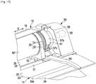
- the opening and closing cover 16 is provided so as to be pivotable (displaceable) between a covering position (position shown in Fig. 18 ) where the roll paper RP loaded into the loading portion 15 is covered and a non-covering position (position shown in Fig. 17 ) where the roll paper RP loaded into the loading portion 15 is not covered.
- a paper feeding port 17 to feed the paper P which is unwound and fed from the roll paper RP loaded into the loading portion 15 to the inside of the main body 14 is formed.
- a transport mechanism (not shown) which transports, along the transport path thereof, the paper P fed from the paper feeding port 17 to a paper discharge port 18 formed on the front portion of the main body 14 is provided.
- a carriage 19 is provided at a position opposing to the transport path of the paper P so as to be reciprocatable in a width direction perpendicular to the transport direction of the paper P.
- a recording head 20 as a recording portion which performs printing as a recording process by reciprocating with the carriage 19 in a scanning direction X perpendicular to the transport direction of the paper P and ejecting ink from nozzles (not shown) onto the paper P transported along the transport path is supported against a position opposing to the transport path of the paper P.
- the scanning direction X is a direction parallel to an axial direction (width direction of the roll paper RP) of the roll paper RP and a longitudinal direction of the main body 14. Furthermore, on, for example, an upper portion of a right end of the main body 14, an operation panel 21 for a user to perform various kinds of setting operations or an input operation of information is provided.
- a maintenance cover 22 to perform the maintenance inside the main body 14 is provided in a center portion in the scanning direction X so as to be freely opened and closed.
- a top plate 23 having a rectangular shape is provided on the half of an upper end portion of the main body 14 in the loading portion 15 side (rear side opposing to the front side).
- the top plate 23 includes a horizontal temporal placing portion 24 to temporally place the roll paper RP (see Fig. 14 ) prior to loading it into the loading portion 15, and an inclined portion 25 inclined so as to descend from the temporal placing portion 24 toward the loading portion 15.
- a positioning recess portion 24a which is used to position the roll paper RP while suppressing the rolling movement at the time of temporally placing the roll paper RP (see Fig. 14 ) is formed so as to extend in the scanning direction X.
- a bottom plate 26 which has a rectangular shape and is parallel to the inclined portion 25 is formed.
- the paper feeding port 17 is positioned between the bottom plate 26 and the inclined portion 25.
- a rear plate 27 having a rectangular shape is installed in a standing manner so as to be perpendicular to the bottom plate 26.
- an area on the bottom plate 26 is a placing portion 28 where the roll paper RP is placed at the time of loading the roll paper RP (see Fig. 15 ) into the loading portion 15. Therefore, the placing portion 28 is positioned at a position lower than the temporal placing portion 24.
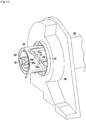
- the support unit 30 includes a shaft member 31 as a medium holding portion which holds the roll paper RP so as to be integrally rotatable with the roll paper RP, and a flange member 32 as a medium support portion which rotatably supports the shaft member 31.
- the upper half of the flange member 32 of the support unit 30 is formed in a semicircular shape and the lower half thereof is formed in a substantially rectangular shape.
- the overall shape of the flange member 32 is formed in a substantially D shape.
- a supporting hole 33 having a circular shape so as to be along an outer edge of the semicircular-shaped portion is formed on the flange member 32 in a penetrating manner.
- the lower surface of the flange member 32 is a flat surface 34 which is flat and has a substantially rectangular shape.
- the shaft member 31 includes a rotating portion 36 having a substantially circular-plate shape, a shaft portion 37 having a cylindrical shape which protrudes on the center portion of a side surface on one side of the rotating portion 36 and is fitted into a center hole H (see Fig. 14 ) or the roll paper RP, and a shaft hole 38 having a circular shape which is formed on a center portion of a side surface (surface on the opposite side to a shaft portion 37 side) on the other side of the rotating portion 36.
- a plurality of engaging pieces 39 is formed on an inner circumferential surface of the shaft hole 38 at the same interval in a circumferential direction.
- An outer diameter of the rotating portion 36 is designed so as to be slightly longer than an outer diameter of the roll paper RP of a maximum diameter.
- Half of the rotating portion 36 on the shaft portion 37 side is rotatably inserted in the supporting hole 33 of the flange member 32, and half of the rotating portion 36 on the opposite side to the shaft portion 37 is exposed.
- a plurality of ribs 40 functioning as slip stoppers when a user manually rotates the shaft member 31 are formed on a circumferential surface of the exposed part from the supporting hole 33 at the same interval in the circumferential direction.
- a first guide member 50 extending in a direction (front-rear direction in Fig. 6 ) perpendicular to the scanning direction X is provided on one end portion (right end portion in Fig. 6 ) in the top plate 23 of the main body 14 in the scanning direction X.
- a second guide member 51 extending in a direction (front-rear direction in Fig. 6 ) perpendicular to the scanning direction X is provided on one end portion (right end portion in Fig. 6 ) in the bottom plate 26 of the loading portion 15 in the scanning direction X.
- One end side (front end side in Fig. 6 ) of the second guide member 51 is in contact with the first guide member 50, and the other end side (rear end side in Fig. 6 ) is perpendicularly bent upward and extends along the rear plate 27.
- the second guide member 51 is in contact with the first guide member 50 such that the surface of the first guide member 50 is approximately in the same plane as the surface of the second guide member 51 corresponding thereto.
- the tip end of the bent portion of the second guide member 51 extends to about half the height of the rear plate 27.
- a third guide member 52 extending parallel to the second guide member 51 is provided on the bottom plate 26.
- an end portion of the third guide member 52 on the opposite side to the top plate 23 side is perpendicularly bent upward and extends along the rear plate 27.
- an interval between the second guide member 51 and the third guide member 52 is designed so as to be slightly wider than the thickness of the flange member 32 (see Fig. 4 ).
- the flange member 32 of the support unit 30 is insertable between the second guide member 51 and the third guide member 52. Also, an end portion of the third guide member 52 on the top plate 23 side is bent at an angle of about 30 degrees on the opposite side to the second guide member 51 side in order to easily insert the flange member 32 between the second guide member 51 and the third guide member 52 from the top plate 23 side.
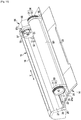
- a torque imparting unit 54 to impart torque to the roll paper RP via the shaft member 31 (see Fig. 3 ) at the time of placing the roll paper RP (see Fig. 3 ) mounted with the support unit 30 on the placing portion 28 is provided at a position (right end portion of the loading portion 15 in Fig. 6 ) opposing to the third guide member 52 interposing the second guide member 51 therebetween.
- the torque imparting unit 54 includes a rotation shaft 55 as a torque transmission portion capable of moving along the scanning direction X retractably with respect to the placing portion 28, a shaft cover 56 covering the rotation shaft 55, an operation portion 57 to operate the rotation shaft 55 so as to be retracted with respect to the placing portion 28, and a rotary driving portion 59 to rotationally drive the rotation shaft 55 disposed in a case 58.
- the rotary driving portion 59 includes a support member 60 which has a cylindrical shape and supports the rotation shaft 55 slide-movably in an axial direction (scanning direction X) thereof, a motor 61 disposed in parallel with the support member 60, and a gear train 62 constituted of a plurality of gears which transmit rotation of the motor 61 to the support member 60.
- an insertion hole 63 in which a base end side of the rotation shaft 55 is slide-movably inserted is formed in a center portion of a surface on the opposite side to the gear train 62 side so as to extend in the axial direction of the support member 60.
- a pair of angular grooves 63a are formed so as to communicate with the insertion hole 63 and extend parallel to the insertion hole 63.
- protrusions (not shown) which are slide-movably inserted in each of the angular grooves 63a at the time of inserting the base end portion of the rotation shaft 55 in the insertion hole 63 are formed.
- the rotation shaft 55 integrally rotates with the support member 60 by respectively engaging the protrusions (not shown) in a rotation direction centering on an axis thereof with the angular grooves 63a.
- the motor 61 is driven and the rotation thereof is transmitted to the support member 60 via the gear train 62, the support member 60 integrally rotates with the rotation shaft 55.
- a plurality of engagement ribs 55a are formed at the same interval in the circumferential direction.
- the tip end portion of the rotation shaft 55 is insertable in the shaft hole 38 (see Fig. 5 ) of the shaft member 31 of the support unit 30. Also, when the tip end portion of the rotation shaft 55 is inserted in the shaft hole 38, the engagement ribs 55a are respectively engaged with the engaging pieces 39 (see Fig. 5 ) in the circumferential direction.
- a ring member 64 having a cylindrical shape is rotatably provided at a position near the base end rather than the tip end portion.
- E-rings 65 are respectively provided on both sides of the ring members 64 in the axial direction in order to regulate the movement of the ring member 64 in the axial direction.
- an accommodation portion 66 which has a cylindrical shape and accommodates the rotation shaft 55 therein is formed on a center portion of the shaft cover 56.
- three through holes 67 which have a rectangular shape and extend in the axial direction are formed at the same interval in the circumferential direction.
- each of convex portions 64a of the ring member 64 is slide-movably inserted in each of the through holes 67.
- the operation portion 57 includes a rotation shaft portion 57a having a cylindrical shape, a shield portion 57b which has a substantially semicircular-ring shape and is formed on a circumferential surface of the rotation shaft portion 57a, and a operation lever 57c which has a substantially rectangular-plate shape and is formed on the circumferential surface of the rotation shaft portion 57a so as to be adjacent to the shield portion 57b.
- the operation portion 57 is installed rotatably with respect to the shaft cover 56 such that the accommodation portion 66 is accommodated in the rotation shaft portion 57a.
- a cam groove forming member 68 having a substantially cylindrical shape is installed so as to be integrally rotatable with the rotation shaft portion 57a.
- the internal diameter of the cam groove forming member 68 is greater than the external diameter of the accommodation portion 66, and the external diameter thereof is smaller than the internal diameter of the rotation shaft portion 57a.
- a cam groove forming wall 69 is provided so as to face the cam groove forming member 68 in the axial direction.
- the position of the cam groove forming member 68 is closer to the tip end side of the accommodation portion 66.
- the cam groove forming member 68 and the cam groove forming wall 69 three cam grooves 70 are formed at the same interval in the circumferential direction of the rotation shaft portion 57a.
- a surface on the cam groove forming wall 69 side is a first cam face 70a and a surface on the cam groove forming member 68 side is a second cam face 70b.
- each of the cam grooves 70 a tip end portion of each of the convex portions 64a of the ring member 64 is slidably inserted. From a position corresponding to a base end portion of the accommodation portion 66 to a position corresponding to a tip end portion of the accommodation portion 66, each of the cam grooves 70 extends obliquely with respect to the circumferential direction of the accommodation portion 66 so as to be along a circumferential surface of the accommodation portion 66.
- each of the convex portions 64a of the ring member 64 is positioned at an end portion on the rotary driving portion 59 side in each of the through holes 67 of the accommodation portion 66.
- a position of the rotation shaft 55 is designated as a non-transmission position (position shown in Figs. 6 and 10 ) where the torque of the rotary driving portion 59 is not transmitted to the roll paper RP via the shaft member 31 of the support unit 30.
- each of the convex portions 64a of the ring member 64 is pressed to the placing portion 28 side by each of the first cam faces 70a and is slidably moved in each of the through holes 67 of the accommodation portion 66 toward an end portion thereof on the placing portion 28 side.
- each of the convex portions 64a of the ring member 64 is moved to the placing portion 28 side along the axial direction. Furthermore, as shown in Figs. 12 and 13 , in a state where the operation lever 57c of the operation portion 57 is moved to the position where the operation lever 57c is positioned lower than the rotation shaft 55, the tip end portion of the rotation shaft 55 protrudes outward the accommodation portion 66, and also each of the convex portions 64a of the ring member 64 is positioned at an end portion on the placing portion 28 side in each of the through holes 67 of the accommodation portion 66.
- a position of the rotation shaft 55 is designated as a transmission position (position shown in Figs. 12 and 13 ) where the torque of the rotary driving portion 59 is transmitted to the roll paper RP via the shaft member 31 of the support unit 30.
- each of the convex portions 64a of the ring member 64 is pressed to the rotary driving portion 59 side by each of the second cam faces 70b and is slidably moved in each of the through holes 67 of the accommodation portion 66 toward an end portion thereof on the rotary driving portion 59 side.
- the rotation shaft 55 is moved to the rotary driving portion 59 side along the axial direction.
- the rotation shaft 55 is moved between the transmission position and the non-transmission position by operating the operation portion 57. Furthermore, in the embodiment, the loading portion 15, the support unit 30, the rotary driving portion 59, the rotation shaft 55, and the operation portion 57 constitute a medium loading device.
- the opening and closing cover 16 When performing printing onto the roll paper RP, first, the opening and closing cover 16 is opened (displaced to the non-covering position), and a user places the roll paper RP on the positioning recess portion 24a of the temporal placing portion 24 in a state where the rotation shaft 55 is placed at the non-transmission position by moving the operation lever 57c upward, as shown in Fig. 14 . Thereupon, the roll paper RP is stable on the positioning recess portion 24a, whereby the rolling of the roll paper RP is suppressed.
- a user fits the shaft portion 37 (see Fig. 4 ) of the shaft member 31 of each of the support units 30 into the center hole H (see Fig. 14 ) of the roll paper RP from both sides thereof, whereby the support units 30 are respectively mounted on both end portions of the roll paper RP. Also, in a state where the support units 30 are respectively mounted on both end portions of the roll paper RP, the roll paper RP is supported by each of the support units 30 in a state where the roll paper RP is lifted from the temporal placing portion 24.
- a user presses the roll paper RP of which both end portions are mounted with the support units 30, namely each of the support units 30 supporting the roll paper RP, from the temporal placing portion 24 toward the placing portion 28.
- each of the support units 30 supporting the roll paper RP is slidably moved on the top plate 23.
- each of the support units 30 supporting the roll paper RP is slidably moved downward on the inclined portion 25 toward the placing portion 28 while the roll paper RP does not rotate.
- the support unit 30 on the first guide member 50 side is introduced between the second guide member 51 and the third guide member 52 in the placing portion 28 while being guided by the first guide member 50.
- the support unit 30 on the first guide member 50 side is inserted between the second guide member 51 and the third guide member 52 in the placing portion 28 while being guided by the second guide member 51 (see Fig. 15 ) and the third guide member 52. Therefore, the positioning of the support unit 30 on the first guide member 50 side in the scanning direction X is performed by the second guide member 51 and the third guide member 52, and consequently the positioning of the roll paper RP in the scanning direction X is performed.
- the shaft hole 38 of the shaft member 31 in the support unit 30 on the first guide member 50 side faces the rotation shaft 55 in the scanning direction X.
- the rotational axis of the rotation shaft 55 coincides with the rotational axis of the roll paper RP (shaft member 31).
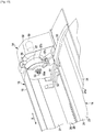
- an access space AS for a user to access (touch) the shaft member 31 in the axial direction (scanning direction X) of the roll paper RP is formed between the shaft member 31 of the support unit 30 on the first guide member 50 side and the rotary driving portion 59 (case 58), namely on the rotary driving portion 59 (case 58) side in the shaft member 31 of the support unit 30 on the first guide member 50 side.
- the operation portion 57 is disposed in the access space AS. In other words, in the axial direction of the roll paper RP when the roll paper RP is loaded into the loading portion 15, the operation portion 57 is disposed between a location of the shaft member 31 when the roll paper RP is loaded and the rotary driving portion 59.
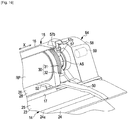
- the shield portion 57b of the operation portion 57 is positioned at the non-shielding position (position shown in Fig. 16 ) where the access space AS is not shielded, as shown in Fig. 16 .
- the shield portion 57b of the operation portion 57 is positioned at the shielding position (position shown in Fig. 17 ) where the access space AS is shielded, as shown in Fig. 17 .
- the shield portion 57b when the operation lever 57c is moved to the upper side, the shield portion 57b is moved to the non-shielding position where the access space AS is opened. However, when the operation lever 57c is moved to the lower side, the shield portion 57b is moved to the shielding position where the access space AS is closed. That is, corresponding to the upward or downward movement (pivot) of the operation lever 57c, the shield portion 57b is moved between the non-shielding position and the shielding position.
- the operation lever 57c is moved to the lower side in a state where the roll paper RP mounted with the support unit 30 is placed at the placing portion 28.
- the rotation shaft 55 is moved to the transmission position, whereby being inserted in the shaft hole 38 of the shaft member 31 in the support unit 30 on the first guide member 50 side.
- the shield portion 57b is moved to the shielding position, whereby shielding the access space AS.
- the operation portion 57 is disposed between the shaft member 31 of the support unit 30 on the first guide member 50 side and the rotary driving portion 59 (case 58), namely at the position adjacent to the rotary driving portion 59 (case 58) side in the shaft member 31 of the support unit 30 on the first guide member 50 side.
- the operation portion 57 is positioned near the support unit 30 on the first guide member 50 side. Therefore, the operation of the operation portion 57 is rapidly and easily carried out by a user.
- the paper P which is unwound and fed from the roll paper RP loaded into the loading portion 15 is inserted from the paper feeding port 17 in the main body 14 along the transport path, and then the opening and closing cover 16 is closed (displaced to the covering position), as shown in Fig. 18 .
- the operation portion 57 is accommodated in the opening and closing cover 16.
- the rotation shaft 55 is rotationally driven by the driving of the motor 61, whereby the torque of the rotation shaft 55 is transmitted to the roll paper RP via the shaft member 31. Therefore, the motor 61 of the rotary driving portion 59 functions as a driving source to rotate the roll paper RP.
- each of the shaft members 31 integrally rotates with the roll paper RP in a direction where the paper P is fed from the roll paper RP. Then, printing is performed onto the paper P fed from the roll paper RP by ejecting ink using the recording head 20 while the paper P is transported along the transport path in the main body 14. After that, the paper P is discharged from the paper discharge port 18.
Landscapes
- Unwinding Webs (AREA)
- Handling Of Continuous Sheets Of Paper (AREA)
- Replacement Of Web Rolls (AREA)
Description
- The present invention relates to a recording apparatus such as an ink jet type printer and a medium loading device provided in the recording apparatus.
- In general, as one type of a recording apparatus, an ink jet type printer has been widely known. These kinds of printers perform printing by supplying ink to a recording head and ejecting the supplied ink onto a recording medium from nozzles of the recording head. In these kinds of printers, a printer using a roll paper as a recording medium has been proposed.
- For example, in the printer according to
JP 2007 261086 - Subsequently, when the movable flange bearer is slidably moved to the fixed flange bearer side along the guide rail, each of the flanges in both ends of the roll paper is fitted into the movable flange bearer and the fixed flange bearer, and is supported. Thereby, the work of setting the roll paper is completed.
- However, in the printer according to PTL 1, if the movable flange bearer is provided with a motor (rotary driving portion) to rotate a roll paper, the weight of the movable flange bearer is increased. Therefore, it is difficult to slidably move the movable flange bearer along the guide rail. As a result, there is a problem in that work efficiency of the work of setting a roll paper is deteriorated.
- Furthermore, this problem is not limited to the ink jet type printer described above, and the same kind of problem can occur in recording apparatuses using a roll paper.
- The invention is made focusing on such a problem of the related art. An object of the invention is to provide a medium loading device and a recording apparatus capable of improving work efficiency for enabling torque of a rotary driving portion to be transmitted to a roll medium loaded into a loading portion.
- In order to achieve the object described above, a medium loading device according to a first aspect of the invention includes: a support unit that has medium holding portions which are mounted on both end portions of a roll medium formed by winding a lengthy medium into a roll shape so as to be integrally rotatable with the roll medium, and a medium support portion which rotatably supports the medium holding portion; and a loading portion in which the roll medium mounted with the support unit is loaded, in which the loading portion includes: a rotary driving portion as a driving source to rotate the roll medium; a torque transmission portion to transmit a torque of the rotary driving portion to the roll medium via the medium holding portion; and an operation portion that moves the torque transmission portion between a transmission position to transmit the torque to the roll medium via the medium holding portion and a non-transmission position not to transmit the torque to the roll medium via the medium holding portion, and in which, in an axial direction of the roll medium when the roll medium is loaded into the loading portion, the operation portion is disposed between the position where the medium holding portion is located when the roll medium is loaded into the loading portion and the rotary driving portion.
- According to the invention, when the roll medium is loaded into the loading portion, the operation portion is disposed at the position near the medium holding portion. Therefore, it is possible to rapidly perform an operation to move the torque transmission portion to the transmission position where the torque of the rotary driving portion is transmitted to the roll medium loaded into the loading portion via the medium holding portion. Consequently, it is possible to improve work efficiency for enabling the torque of the rotary driving portion to be transmitted to the roll medium loaded into the loading portion.
- In the medium loading device of the invention, an access space to access the medium holding portion in the axial direction of the roll medium is formed between the position where the medium holding portion is located when the roll medium is loaded and the rotary driving portion. Also, the operation portion includes: an operation lever to perform the operation; and a shield portion that is moved between a shielding position to shield the access space and a non-shielding position not to shield the access space corresponding to the operation of the operation lever, in which, when the shield portion is moved to the shielding position, the torque transmission portion is moved to the transmission position, and when the shield portion is moved to the non-shielding position, the torque transmission portion is moved to the non-transmission position.
- According to the invention, when the torque transmission portion transmits the torque of the rotary driving portion to the roll medium via the medium holding portion, the access space is shielded by the shield portion. Therefore, it is possible to regulate the access of a user to the medium holding portion when rotating. On the other hand, when the torque transmission portion does not transmit the torque of the rotary driving portion to the roll medium via the medium holding portion, the access space is not shielded by the shield portion. Therefore, it is possible to allow the access of a user to the medium holding portion when stopping.
- In the medium loading device of the invention, the operation portion is configured such that, when the operation lever is moved to a lower side, the shield portion is moved to the shielding position, and when the operation lever is moved to an upper side, the shield portion is moved to the non-shielding position.
- According to the invention, when the torque transmission portion transmits the torque to the roll medium via the medium holding portion, the shield portion is moved to the shielding position by moving the operation lever to the lower side. Therefore, it is possible for the operation lever not to hinder the medium holding portion when rotating.
- The medium loading device of the invention further includes a cover member that is displaceable between a covering position where the roll medium loaded into the loading portion is covered and a non-covering position where the roll medium loaded into the loading portion is not covered, in which, when the cover member is positioned at the covering position, the operation portion is accommodated in the cover member.
- According to the invention, since the operation portion is accommodated in the cover member by displacing the cover member to the covering position, it is possible to suppress the erroneous contact of a user to the operation portion.
- According to a second aspect of the invention, there is provided a medium loading device comprising a loading portion, the loading portion for loading a roll medium with a support unit including a medium holding portion mounted to be integrally rotatable with the roll medium, the support unit further comprising a medium support portion to rotatably support the medium holding portion, wherein the loading portion includes a rotary driving portion as a driving source to rotate the roll medium, a torque transmission portion to transmit a torque of the rotary driving portion to the roll medium via the medium holding portion, and an operation portion that moves the torque transmission portion, wherein, when the roll medium is loaded, the operation portion is disposed between the rotary driving portion and the medium holding portion.
- A recording apparatus according to a third aspect of the invention includes the medium loading device configured as above and a recording portion to perform a recording process onto the roll medium fed from the medium loading device.
- According to the invention, it is possible to achieve the same action effect with the case of the medium loading device described above.
-
- [
fig.1]Fig. 1 is a perspective view of an ink jet type printer according to an embodiment. - [
fig.2]Fig. 2 is a perspective view of a main portion of the printer. - [
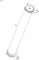
fig.3]Fig. 3 is a perspective view of a roll paper mounted with a support unit. - [
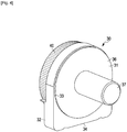
fig.4]Fig. 4 is a perspective view of the support unit. - [
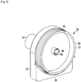
fig.5]Fig. 5 is a perspective view of the support unit. - [
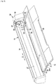
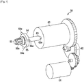
fig.6]Fig. 6 is an enlarged perspective view of a main portion inFig. 2 . - [
fig.7]Fig. 7 is a perspective view showing a connection state between a rotary driving portion and a rotation shaft. - [
fig.8]Fig. 8 is an enlarged perspective view showing a state where a shaft cover covers the rotation shaft. - [
fig.9]Fig. 9 is a perspective view showing a state where an operation portion is installed on the shaft cover inFig. 8 . - [
fig.10]Fig. 10 is a perspective view showing a cam groove formed of a cam groove forming member and a cam groove forming wall. - [
fig.11]Fig. 11 is a perspective view showing a state when a convex portion of a ring member slidably moves in the cam groove. - [
fig. 12] Fig. 12 is a perspective view showing a positional relationship between the cam groove and the convex portion of the ring member when the rotation shaft is located at a transmission position. - [
fig.13]Fig. 13 is an enlarged perspective view of a main portion in a state where the operation lever is moved downward inFig. 6 . - [
fig.14]Fig. 14 is a perspective view showing a state where the roll paper is placed at a temporal placing portion inFig. 2 . - [
fig.15]Fig. 15 is a perspective view showing a state where the support unit is mounted on the roll paper inFig. 14 . - [
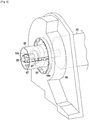
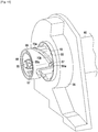
fig.16]Fig. 16 is a perspective view showing a state where the roll paper mounted with the support unit is loaded into the loading portion inFig. 6 . - [
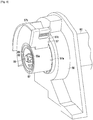
fig.17]Fig. 17 is a perspective view showing a state where the operation lever is moved downward inFig. 16 . - [
fig.18]Fig. 18 is a perspective view showing a state where an opening and closing cover is closed inFig. 17 . - Hereinafter, an embodiment embodying a recording apparatus of the invention in an ink jet type printer will be described with reference to drawings.
- As shown in
Fig. 1 , an inkjet type printer 11 as a recording apparatus is supported by aleg base 12. The inkjet type printer 11 includes amain body 14 having a substantially rectangular shape and aloading portion 15. Theloading portion 15 is provided so as to obliquely protrude from a rear portion of themain body 14 to a rear upper side, and loads a roll paper RP which is formed by winding a paper P as a lengthy medium into a roll shape and used as a roll medium therein. - In an upper end portion of the
loading portion 15, an opening andclosing cover 16 as a cover member is provided so as to be freely opened and closed. In other words, the opening andclosing cover 16 is provided so as to be pivotable (displaceable) between a covering position (position shown inFig. 18 ) where the roll paper RP loaded into theloading portion 15 is covered and a non-covering position (position shown inFig. 17 ) where the roll paper RP loaded into theloading portion 15 is not covered. - In a boundary position between the lower end portion of the
loading portion 15 and themain body 14, apaper feeding port 17 to feed the paper P which is unwound and fed from the roll paper RP loaded into theloading portion 15 to the inside of themain body 14 is formed. In themain body 14, a transport mechanism (not shown) which transports, along the transport path thereof, the paper P fed from thepaper feeding port 17 to apaper discharge port 18 formed on the front portion of themain body 14 is provided. - In the
main body 14, acarriage 19 is provided at a position opposing to the transport path of the paper P so as to be reciprocatable in a width direction perpendicular to the transport direction of the paper P. In thecarriage 19, arecording head 20 as a recording portion which performs printing as a recording process by reciprocating with thecarriage 19 in a scanning direction X perpendicular to the transport direction of the paper P and ejecting ink from nozzles (not shown) onto the paper P transported along the transport path is supported against a position opposing to the transport path of the paper P. - The scanning direction X is a direction parallel to an axial direction (width direction of the roll paper RP) of the roll paper RP and a longitudinal direction of the
main body 14. Furthermore, on, for example, an upper portion of a right end of themain body 14, anoperation panel 21 for a user to perform various kinds of setting operations or an input operation of information is provided. - On the front side in an upper portion of the
main body 14, amaintenance cover 22 to perform the maintenance inside themain body 14 is provided in a center portion in the scanning direction X so as to be freely opened and closed. On the other hand, atop plate 23 having a rectangular shape is provided on the half of an upper end portion of themain body 14 in theloading portion 15 side (rear side opposing to the front side). - As shown in
Fig. 2 , thetop plate 23 includes a horizontaltemporal placing portion 24 to temporally place the roll paper RP (seeFig. 14 ) prior to loading it into theloading portion 15, and aninclined portion 25 inclined so as to descend from thetemporal placing portion 24 toward theloading portion 15. In thetemporal placing portion 24, apositioning recess portion 24a which is used to position the roll paper RP while suppressing the rolling movement at the time of temporally placing the roll paper RP (seeFig. 14 ) is formed so as to extend in the scanning direction X. - On the lower end portion of the
loading portion 15, abottom plate 26 which has a rectangular shape and is parallel to theinclined portion 25 is formed. In this case, thepaper feeding port 17 is positioned between thebottom plate 26 and theinclined portion 25. On an end portion on the opposite side to thepaper feeding port 17 side in thebottom plate 26, arear plate 27 having a rectangular shape is installed in a standing manner so as to be perpendicular to thebottom plate 26. Also, an area on thebottom plate 26 is a placingportion 28 where the roll paper RP is placed at the time of loading the roll paper RP (seeFig. 15 ) into theloading portion 15. Therefore, the placingportion 28 is positioned at a position lower than thetemporal placing portion 24. - As shown in
Figs. 2 and3 , when the roll paper RP is loaded into theloading portion 15,support units 30 to rotatably support the roll paper RP are mounted on the both end portions of the roll paper RP. In other words, thesupport unit 30 includes ashaft member 31 as a medium holding portion which holds the roll paper RP so as to be integrally rotatable with the roll paper RP, and aflange member 32 as a medium support portion which rotatably supports theshaft member 31. - As shown in
Figs. 4 and5 , the upper half of theflange member 32 of thesupport unit 30 is formed in a semicircular shape and the lower half thereof is formed in a substantially rectangular shape. In other words, the overall shape of theflange member 32 is formed in a substantially D shape. A supportinghole 33 having a circular shape so as to be along an outer edge of the semicircular-shaped portion is formed on theflange member 32 in a penetrating manner. The lower surface of theflange member 32 is aflat surface 34 which is flat and has a substantially rectangular shape. - The
shaft member 31 includes a rotatingportion 36 having a substantially circular-plate shape, ashaft portion 37 having a cylindrical shape which protrudes on the center portion of a side surface on one side of the rotatingportion 36 and is fitted into a center hole H (seeFig. 14 ) or the roll paper RP, and ashaft hole 38 having a circular shape which is formed on a center portion of a side surface (surface on the opposite side to ashaft portion 37 side) on the other side of the rotatingportion 36. A plurality of engagingpieces 39 is formed on an inner circumferential surface of theshaft hole 38 at the same interval in a circumferential direction. - An outer diameter of the rotating
portion 36 is designed so as to be slightly longer than an outer diameter of the roll paper RP of a maximum diameter. Half of the rotatingportion 36 on theshaft portion 37 side is rotatably inserted in the supportinghole 33 of theflange member 32, and half of the rotatingportion 36 on the opposite side to theshaft portion 37 is exposed. In the rotatingportion 36, a plurality ofribs 40 functioning as slip stoppers when a user manually rotates theshaft member 31 are formed on a circumferential surface of the exposed part from the supportinghole 33 at the same interval in the circumferential direction. - As shown in
Fig. 6 , afirst guide member 50 extending in a direction (front-rear direction inFig. 6 ) perpendicular to the scanning direction X is provided on one end portion (right end portion inFig. 6 ) in thetop plate 23 of themain body 14 in the scanning direction X. Furthermore, asecond guide member 51 extending in a direction (front-rear direction inFig. 6 ) perpendicular to the scanning direction X is provided on one end portion (right end portion inFig. 6 ) in thebottom plate 26 of theloading portion 15 in the scanning direction X. - One end side (front end side in
Fig. 6 ) of thesecond guide member 51 is in contact with thefirst guide member 50, and the other end side (rear end side inFig. 6 ) is perpendicularly bent upward and extends along therear plate 27. In this case, thesecond guide member 51 is in contact with thefirst guide member 50 such that the surface of thefirst guide member 50 is approximately in the same plane as the surface of thesecond guide member 51 corresponding thereto. In addition, the tip end of the bent portion of thesecond guide member 51 extends to about half the height of therear plate 27. - Still further, a
third guide member 52 extending parallel to thesecond guide member 51 is provided on thebottom plate 26. As similar to thesecond guide member 51, an end portion of thethird guide member 52 on the opposite side to thetop plate 23 side is perpendicularly bent upward and extends along therear plate 27. In this case, an interval between thesecond guide member 51 and thethird guide member 52 is designed so as to be slightly wider than the thickness of the flange member 32 (seeFig. 4 ). - Therefore, when the roll paper RP (see
Fig. 3 ) mounted with thesupport unit 30 is loaded into theloading portion 15, theflange member 32 of thesupport unit 30 is insertable between thesecond guide member 51 and thethird guide member 52. Also, an end portion of thethird guide member 52 on thetop plate 23 side is bent at an angle of about 30 degrees on the opposite side to thesecond guide member 51 side in order to easily insert theflange member 32 between thesecond guide member 51 and thethird guide member 52 from thetop plate 23 side. - In the
loading portion 15, atorque imparting unit 54 to impart torque to the roll paper RP via the shaft member 31 (seeFig. 3 ) at the time of placing the roll paper RP (seeFig. 3 ) mounted with thesupport unit 30 on the placingportion 28 is provided at a position (right end portion of theloading portion 15 inFig. 6 ) opposing to thethird guide member 52 interposing thesecond guide member 51 therebetween. - The
torque imparting unit 54 includes arotation shaft 55 as a torque transmission portion capable of moving along the scanning direction X retractably with respect to the placingportion 28, ashaft cover 56 covering therotation shaft 55, anoperation portion 57 to operate therotation shaft 55 so as to be retracted with respect to the placingportion 28, and arotary driving portion 59 to rotationally drive therotation shaft 55 disposed in acase 58. - As shown in
Fig. 7 , therotary driving portion 59 includes asupport member 60 which has a cylindrical shape and supports therotation shaft 55 slide-movably in an axial direction (scanning direction X) thereof, amotor 61 disposed in parallel with thesupport member 60, and agear train 62 constituted of a plurality of gears which transmit rotation of themotor 61 to thesupport member 60. - In the
support member 60, aninsertion hole 63 in which a base end side of therotation shaft 55 is slide-movably inserted is formed in a center portion of a surface on the opposite side to thegear train 62 side so as to extend in the axial direction of thesupport member 60. - On both sides of the
support member 60 which face each other interposing theinsertion hole 63, a pair ofangular grooves 63a are formed so as to communicate with theinsertion hole 63 and extend parallel to theinsertion hole 63. On a base end portion of therotation shaft 55, protrusions (not shown) which are slide-movably inserted in each of theangular grooves 63a at the time of inserting the base end portion of therotation shaft 55 in theinsertion hole 63 are formed. - Therefore, the
rotation shaft 55 integrally rotates with thesupport member 60 by respectively engaging the protrusions (not shown) in a rotation direction centering on an axis thereof with theangular grooves 63a. In other words, if themotor 61 is driven and the rotation thereof is transmitted to thesupport member 60 via thegear train 62, thesupport member 60 integrally rotates with therotation shaft 55. - On a circumferential surface of a tip end portion of the
rotation shaft 55, a plurality ofengagement ribs 55a are formed at the same interval in the circumferential direction. The tip end portion of therotation shaft 55 is insertable in the shaft hole 38 (seeFig. 5 ) of theshaft member 31 of thesupport unit 30. Also, when the tip end portion of therotation shaft 55 is inserted in theshaft hole 38, theengagement ribs 55a are respectively engaged with the engaging pieces 39 (seeFig. 5 ) in the circumferential direction. - Therefore, if the
rotation shaft 55 is rotationally driven in a state where the tip end portion of therotation shaft 55 is inserted in the shaft hole 38 (seeFig. 5 ) of theshaft member 31, theengagement ribs 55a are respectively engaged with the engaging pieces 39 (seeFig. 5 ) in the rotation direction. Thereby, the torque is transmitted from therotation shaft 55 to theshaft member 31. In therotation shaft 55, aring member 64 having a cylindrical shape is rotatably provided at a position near the base end rather than the tip end portion. - In the
rotation shaft 55, E-rings 65 are respectively provided on both sides of thering members 64 in the axial direction in order to regulate the movement of thering member 64 in the axial direction. On a circumferential surface of thering member 64, threeconvex portions 64a protruding in a radial direction are provided at the same interval in the circumferential direction. - As shown in
Fig. 8 , anaccommodation portion 66 which has a cylindrical shape and accommodates therotation shaft 55 therein is formed on a center portion of theshaft cover 56. On a peripheral wall of theaccommodation portion 66, three throughholes 67 which have a rectangular shape and extend in the axial direction are formed at the same interval in the circumferential direction. In addition, each ofconvex portions 64a of thering member 64 is slide-movably inserted in each of the through holes 67. - As shown in
Fig. 9 , theoperation portion 57 includes arotation shaft portion 57a having a cylindrical shape, ashield portion 57b which has a substantially semicircular-ring shape and is formed on a circumferential surface of therotation shaft portion 57a, and aoperation lever 57c which has a substantially rectangular-plate shape and is formed on the circumferential surface of therotation shaft portion 57a so as to be adjacent to theshield portion 57b. In addition, theoperation portion 57 is installed rotatably with respect to theshaft cover 56 such that theaccommodation portion 66 is accommodated in therotation shaft portion 57a. - As shown in
Figs. 9 and10 , on an inner circumferential surface of therotation shaft portion 57a, a camgroove forming member 68 having a substantially cylindrical shape is installed so as to be integrally rotatable with therotation shaft portion 57a. The internal diameter of the camgroove forming member 68 is greater than the external diameter of theaccommodation portion 66, and the external diameter thereof is smaller than the internal diameter of therotation shaft portion 57a. In addition, on the inner circumferential surface of therotation shaft portion 57a, a camgroove forming wall 69 is provided so as to face the camgroove forming member 68 in the axial direction. - In this case, upon comparison with the position of the cam
groove forming wall 69, the position of the camgroove forming member 68 is closer to the tip end side of theaccommodation portion 66. In addition, by the camgroove forming member 68 and the camgroove forming wall 69, threecam grooves 70 are formed at the same interval in the circumferential direction of therotation shaft portion 57a. In thecam groove 70, a surface on the camgroove forming wall 69 side is afirst cam face 70a and a surface on the camgroove forming member 68 side is asecond cam face 70b. - In each of the
cam grooves 70, a tip end portion of each of theconvex portions 64a of thering member 64 is slidably inserted. From a position corresponding to a base end portion of theaccommodation portion 66 to a position corresponding to a tip end portion of theaccommodation portion 66, each of thecam grooves 70 extends obliquely with respect to the circumferential direction of theaccommodation portion 66 so as to be along a circumferential surface of theaccommodation portion 66. - As shown in
Figs. 6 and10 , in a state where theoperation lever 57c of theoperation portion 57 is positioned higher than therotation shaft 55, the tip end portion of therotation shaft 55 is accommodated in theaccommodation portion 66, and also each of theconvex portions 64a of thering member 64 is positioned at an end portion on therotary driving portion 59 side in each of the throughholes 67 of theaccommodation portion 66. - In this case, when the roll paper RP (see
Fig. 3 ) mounted with thesupport unit 30 is placed at the placingportion 28, a position of therotation shaft 55 is designated as a non-transmission position (position shown inFigs. 6 and10 ) where the torque of therotary driving portion 59 is not transmitted to the roll paper RP via theshaft member 31 of thesupport unit 30. - Subsequently, in this state, when the
operation lever 57c is operated such that theoperation lever 57c of theoperation portion 57 is moved (pivoted) toward a position where theoperation lever 57c is positioned lower than therotation shaft 55, as shown inFig. 13 , therotation shaft 55 is moved while each of theconvex portions 64a of thering member 64 slides on each of the first cam faces 70a, as shown inFig. 11 . Thereby, as shown inFigs. 11 and13 , each of theconvex portions 64a of thering member 64 is pressed to the placingportion 28 side by each of the first cam faces 70a and is slidably moved in each of the throughholes 67 of theaccommodation portion 66 toward an end portion thereof on the placingportion 28 side. - Corresponding to the slide-movement of each of the
convex portions 64a of thering member 64, therotation shaft 55 is moved to the placingportion 28 side along the axial direction. Furthermore, as shown inFigs. 12 and13 , in a state where theoperation lever 57c of theoperation portion 57 is moved to the position where theoperation lever 57c is positioned lower than therotation shaft 55, the tip end portion of therotation shaft 55 protrudes outward theaccommodation portion 66, and also each of theconvex portions 64a of thering member 64 is positioned at an end portion on the placingportion 28 side in each of the throughholes 67 of theaccommodation portion 66. - In this case, when the roll paper RP (see
Fig. 3 ) mounted with thesupport unit 30 is placed at the placingportion 28, a position of therotation shaft 55 is designated as a transmission position (position shown inFigs. 12 and13 ) where the torque of therotary driving portion 59 is transmitted to the roll paper RP via theshaft member 31 of thesupport unit 30. - Furthermore, in the case of moving the
rotation shaft 55 from the transmission position to the non-transmission position, when theoperation lever 57c is operated such that theoperation lever 57c of theoperation portion 57 is moved (pivoted) to the position where theoperation lever 57c is positioned higher than therotation shaft 55, as shown inFig. 6 , therotation shaft 55 is moved while each of theconvex portions 64a of thering member 64 slides on each of the second cam faces 70b, as shown inFig. 11 . - Thereby, as shown in
Figs. 6 and11 , each of theconvex portions 64a of thering member 64 is pressed to therotary driving portion 59 side by each of the second cam faces 70b and is slidably moved in each of the throughholes 67 of theaccommodation portion 66 toward an end portion thereof on therotary driving portion 59 side. Corresponding to the slide-movement of each of theconvex portions 64a of thering member 64, therotation shaft 55 is moved to therotary driving portion 59 side along the axial direction. - Furthermore, as shown in
Figs. 6 and10 , in a state where theoperation lever 57c of theoperation portion 57 is moved to the position where theoperation lever 57c is positioned higher than therotation shaft 55, the tip end portion of therotation shaft 55 is accommodated in theaccommodation portion 66, and also each of theconvex portions 64a of thering member 64 is positioned at an end portion on therotary driving portion 59 side in each of the throughholes 67 of theaccommodation portion 66. In this manner, therotation shaft 55 is moved from the transmission position to the non-transmission position. - Subsequently, the
rotation shaft 55 is moved between the transmission position and the non-transmission position by operating theoperation portion 57. Furthermore, in the embodiment, theloading portion 15, thesupport unit 30, therotary driving portion 59, therotation shaft 55, and theoperation portion 57 constitute a medium loading device. - Next, the operation of the ink
jet type printer 11 will be described. - When performing printing onto the roll paper RP, first, the opening and closing
cover 16 is opened (displaced to the non-covering position), and a user places the roll paper RP on thepositioning recess portion 24a of thetemporal placing portion 24 in a state where therotation shaft 55 is placed at the non-transmission position by moving theoperation lever 57c upward, as shown inFig. 14 . Thereupon, the roll paper RP is stable on thepositioning recess portion 24a, whereby the rolling of the roll paper RP is suppressed. - Subsequently, as shown in
Fig. 15 , a user fits the shaft portion 37 (seeFig. 4 ) of theshaft member 31 of each of thesupport units 30 into the center hole H (seeFig. 14 ) of the roll paper RP from both sides thereof, whereby thesupport units 30 are respectively mounted on both end portions of the roll paper RP. Also, in a state where thesupport units 30 are respectively mounted on both end portions of the roll paper RP, the roll paper RP is supported by each of thesupport units 30 in a state where the roll paper RP is lifted from thetemporal placing portion 24. - Next, a user presses the roll paper RP of which both end portions are mounted with the
support units 30, namely each of thesupport units 30 supporting the roll paper RP, from thetemporal placing portion 24 toward the placingportion 28. - Thereupon, each of the
support units 30 supporting the roll paper RP is slidably moved on thetop plate 23. In other words, each of thesupport units 30 supporting the roll paper RP is slidably moved downward on theinclined portion 25 toward the placingportion 28 while the roll paper RP does not rotate. In this case, thesupport unit 30 on thefirst guide member 50 side is introduced between thesecond guide member 51 and thethird guide member 52 in the placingportion 28 while being guided by thefirst guide member 50. - Subsequently, when a user presses each of the
support units 30 to the placingportion 28 side, the roll paper RP is placed at the placingportion 28 in a state of being supported by each of thesupport units 30, as shown inFig. 16 . - In this case, the
support unit 30 on thefirst guide member 50 side is inserted between thesecond guide member 51 and thethird guide member 52 in the placingportion 28 while being guided by the second guide member 51 (seeFig. 15 ) and thethird guide member 52. Therefore, the positioning of thesupport unit 30 on thefirst guide member 50 side in the scanning direction X is performed by thesecond guide member 51 and thethird guide member 52, and consequently the positioning of the roll paper RP in the scanning direction X is performed. - Furthermore, in a state where the roll paper RP mounted with the
support unit 30 is placed at the placingportion 28, theshaft hole 38 of theshaft member 31 in thesupport unit 30 on thefirst guide member 50 side faces therotation shaft 55 in the scanning direction X. In other words, the rotational axis of therotation shaft 55 coincides with the rotational axis of the roll paper RP (shaft member 31). - In this case, an access space AS for a user to access (touch) the
shaft member 31 in the axial direction (scanning direction X) of the roll paper RP is formed between theshaft member 31 of thesupport unit 30 on thefirst guide member 50 side and the rotary driving portion 59 (case 58), namely on the rotary driving portion 59 (case 58) side in theshaft member 31 of thesupport unit 30 on thefirst guide member 50 side. - In addition, the
operation portion 57 is disposed in the access space AS. In other words, in the axial direction of the roll paper RP when the roll paper RP is loaded into theloading portion 15, theoperation portion 57 is disposed between a location of theshaft member 31 when the roll paper RP is loaded and therotary driving portion 59. - Here, when the
operation lever 57c of theoperation portion 57 is positioned at the upper side, theshield portion 57b of theoperation portion 57 is positioned at the non-shielding position (position shown inFig. 16 ) where the access space AS is not shielded, as shown inFig. 16 . On the other hand, when theoperation lever 57c of theoperation portion 57 is positioned at the lower side, theshield portion 57b of theoperation portion 57 is positioned at the shielding position (position shown inFig. 17 ) where the access space AS is shielded, as shown inFig. 17 . - In other words, when the
operation lever 57c is moved to the upper side, theshield portion 57b is moved to the non-shielding position where the access space AS is opened. However, when theoperation lever 57c is moved to the lower side, theshield portion 57b is moved to the shielding position where the access space AS is closed. That is, corresponding to the upward or downward movement (pivot) of theoperation lever 57c, theshield portion 57b is moved between the non-shielding position and the shielding position. - Therefore, when the
shield portion 57b is moved to the shielding position, therotation shaft 55 is moved to the transmission position, and when theshield portion 57b is moved to the non-shielding position, therotation shaft 55 is moved to the non-transmission position, by operating theoperation lever 57c. - Subsequently, as shown in
Fig. 17 , theoperation lever 57c is moved to the lower side in a state where the roll paper RP mounted with thesupport unit 30 is placed at the placingportion 28. Thereupon, therotation shaft 55 is moved to the transmission position, whereby being inserted in theshaft hole 38 of theshaft member 31 in thesupport unit 30 on thefirst guide member 50 side. Also, theshield portion 57b is moved to the shielding position, whereby shielding the access space AS. - In this case, the
operation portion 57 is disposed between theshaft member 31 of thesupport unit 30 on thefirst guide member 50 side and the rotary driving portion 59 (case 58), namely at the position adjacent to the rotary driving portion 59 (case 58) side in theshaft member 31 of thesupport unit 30 on thefirst guide member 50 side. In other words, theoperation portion 57 is positioned near thesupport unit 30 on thefirst guide member 50 side. Therefore, the operation of theoperation portion 57 is rapidly and easily carried out by a user. - Next, the paper P which is unwound and fed from the roll paper RP loaded into the
loading portion 15 is inserted from thepaper feeding port 17 in themain body 14 along the transport path, and then the opening and closingcover 16 is closed (displaced to the covering position), as shown inFig. 18 . In this case, theoperation portion 57 is accommodated in the opening and closingcover 16. Subsequently, when theoperation panel 21 is operated to start the printing process, therotation shaft 55 is rotationally driven by the driving of themotor 61, whereby the torque of therotation shaft 55 is transmitted to the roll paper RP via theshaft member 31. Therefore, themotor 61 of therotary driving portion 59 functions as a driving source to rotate the roll paper RP. - Thereupon, each of the
shaft members 31 integrally rotates with the roll paper RP in a direction where the paper P is fed from the roll paper RP. Then, printing is performed onto the paper P fed from the roll paper RP by ejecting ink using therecording head 20 while the paper P is transported along the transport path in themain body 14. After that, the paper P is discharged from thepaper discharge port 18. - According to the embodiment described in detail hereinbefore, it is possible to achieve the effects described below.
- (1) In the axial direction of the roll paper RP when the roll paper RP is loaded into the
loading portion 15, theoperation portion 57 is disposed between the location of theshaft member 31 of thesupport unit 30 on thefirst guide member 50 side when the roll paper RP is loaded and the rotary driving portion 59 (case 58), namely at the position adjacent to the rotary driving portion 59 (case 58) side in theshaft member 31 of thesupport unit 30 on thefirst guide member 50 side. In other words, theoperation portion 57 is disposed at the position near theshaft member 31 of thesupport unit 30 on thefirst guide member 50 side. Therefore, it is possible for a user to rapidly perform the operation to move therotation shaft 55 to the transmission position. Consequently, it is possible to improve work efficiency for enabling the torque of therotary driving portion 59 to be transmitted to the roll paper RP loaded into theloading portion 15. - (2) When the
shield portion 57b is moved to the shielding position, therotation shaft 55 is moved to the transmission position, and when theshield portion 57b is moved to the non-shielding position, therotation shaft 55 is moved to the non-transmission position, by operating theoperation lever 57c. Therefore, when therotation shaft 55 transmits the torque of therotary driving portion 59 to the roll paper RP via theshaft member 31, the access space AS is shielded by theshield portion 57b. Thereby, it is possible to regulate the access of a user to theshaft member 31 when rotating. On the other hand, when therotation shaft 55 does not transmit the torque of therotary driving portion 59 to the roll paper RP via theshaft member 31, the access space AS is not shielded by theshield portion 57b. Thereby, it is possible to allow the access of a user to theshaft member 31 when stopping. - (3) The
operation portion 57 is configured such that, when theoperation lever 57c is moved to the lower side, theshield portion 57b is moved to the shielding position, and when theoperation lever 57c is moved to the upper side, theshield portion 57b is moved to the non-shielding position. Therefore, when therotation shaft 55 transmits the torque to the roll paper RP via theshaft member 31, theshield portion 57b is moved to the shielding position by moving theoperation lever 57c to the lower side. Consequently, since, when theshaft member 31 rotates, theoperation lever 57c is positioned at the lower side, it is possible for theoperation lever 57c not to hinder theshaft member 31. - (4) When the opening and closing
cover 16 is positioned at the covering position, theoperation portion 57 is accommodated in the opening and closingcover 16. Therefore, by closing (displacing to the covering position) the opening and closingcover 16 when theshaft member 31 rotates, it is possible to suppress the erroneous contact of a user to theoperation portion 57 when theshaft member 31 rotates. - Furthermore, the embodiment described above may be modified as follows.
- * When the opening and closing
cover 16 is positioned at the covering position, it is not necessary for theoperation portion 57 always to be accommodated in the opening and closingcover 16. - * The opening and closing
cover 16 may be omitted. - * The
operation portion 57 may be configured such that, when theoperation lever 57c is moved to the lower side, theshield portion 57b is moved to the non-shielding position, and when theoperation lever 57c is moved to the upper side, theshield portion 57b is moved to the shielding position. - * In the
operation portion 57, theshield portion 57b may be omitted. - * Instead of the roll paper RP, plastic film, cloth, foil or the like may be used as a roll medium.
- * In the embodiment described above, the recording apparatus may be a fluid ejecting apparatus which performs recording by ejecting or discharging a fluid (including a liquid, liquid body which is composed by dispersing or mixing a liquid or particles of a functional material in a liquid, a fluid body such as gel, and solid matter capable of being ejected as a fluid) aside from ink. For example, a liquid body ejecting apparatus which performs recording by ejecting a liquid body including a material such as an electrode material or a colorant material (pixel material) used for manufacturing a liquid-crystal display, an EL (electronic luminescence) display and a surface-emission display by a manner of dispersion or dissolution may be employed. Furthermore, a fluid body ejecting apparatus which ejects a fluid body such as gel (for example, physical gel) may be employed. Also, the invention can be applied to any one of the fluid ejecting apparatuses described above. In addition, "fluid" in the specification does not include a fluid composed of a gaseous body only, and includes a liquid (such as inorganic solvents, organic solvents, liquid solutions, liquid resins, and liquid metals (metallic melts)), a liquid body, a fluid body or the like, for example.
-
- 11: Ink jet type printer as a recording apparatus
- 15: Loading portion constituting a medium loading device
- 16: Opening and closing cover as a cover member
- 20: Recording head as a recording portion
- 30: Support unit constituting the medium loading device
- 31: Shaft member as a medium holding portion
- 32: Flange member as a medium support portion
- 55: Rotation shaft as a torque transmission portion constituting the medium loading device
- 57: Operation portion constituting the medium loading device
- 57b: Shield portion
- 57c: Operation lever
- 59: Rotary driving portion constituting the medium loading device
- AS: Access space
- P: Paper as a medium
- RP: Roll paper as a roll medium
Claims (5)
- A medium loading device comprising:a support unit (30) that has medium holding portions (31) which are mountable on both end portions of a roll medium (RP) formed by winding a lengthy medium into a roll shape so as to be integrally rotatable with the roll medium; anda loading portion (15) in which the roll medium mounted with the support unit is loadable,wherein the loading portion includes:a rotary driving portion (59) as a driving source to rotate the roll medium; anda torque transmission portion (55) to transmit a torque of the rotary driving portion to the roll medium via the medium holding portion, characterized in that:the support unit further comprises a medium support portion (32) to rotatably support the medium holding portion;the loading portion further comprises an operation portion (57) that moves the torque transmission portion between a transmission position to transmit the torque to the roll medium via the medium holding portion and a non-transmission position not to transmit the torque to the roll medium via the medium holding portion, andin an axial direction of the roll medium when the roll medium is loaded into the loading portion, the operation portion is disposed between the position where the medium holding portion is located when the roll medium is loaded and the rotary driving portion.
- The medium loading device according to Claim 1,
wherein, an access space (AS) to access the medium holding portion in the axial direction of the roll medium is formed between the position where the medium holding portion is located when the roll medium is loaded and the rotary driving portion,
wherein the operation portion includes:an operation lever (57c) to perform operation; anda shield portion (57b) that is moved between a shielding position to shield the access space and a non-shielding position not to shield the access space corresponding to the operation of the operation lever, andwherein, when the shield portion is moved to the shielding position, the torque transmission portion is moved to the transmission position, andwhen the shield portion is moved to the non-shielding position, the torque transmission portion is moved to the non-transmission position. - The medium loading device according to Claim 2,
wherein, in the operation portion, when the operation lever is moved to a lower side, the shield portion is moved to the shielding position, and
when the operation lever is moved to an upper side, the shield portion is moved to the non-shielding position. - The medium loading device according to any one of Claims 1 to 3,
further comprising,
a cover member (16) that is displaceable between a covering position where the roll medium loaded into the loading portion is covered and a noncovering position where the roll medium loaded into the loading portion is not covered,
wherein, when the cover member is positioned at the covering position,
the operation portion is accommodated in the cover member. - A recording apparatus comprising:the medium loading device according to any one of Claims 1 to 4; anda recording portion (20) to perform a recording process onto the roll medium fed from the medium loading device.
Applications Claiming Priority (2)
| Application Number | Priority Date | Filing Date | Title |
|---|---|---|---|
| JP2012090275A JP5821760B2 (en) | 2012-04-11 | 2012-04-11 | Medium loading apparatus and recording apparatus |
| PCT/JP2013/001851 WO2013153747A1 (en) | 2012-04-11 | 2013-03-19 | Medium loading device and recording apparatus |
Publications (2)
| Publication Number | Publication Date |
|---|---|
| EP2836450A1 EP2836450A1 (en) | 2015-02-18 |
| EP2836450B1 true EP2836450B1 (en) | 2017-08-02 |
Family
ID=48093054
Family Applications (1)
| Application Number | Title | Priority Date | Filing Date |
|---|---|---|---|
| EP13716069.3A Active EP2836450B1 (en) | 2012-04-11 | 2013-03-19 | Medium loading device and recording apparatus |
Country Status (6)
| Country | Link |
|---|---|
| US (1) | US9302510B2 (en) |
| EP (1) | EP2836450B1 (en) |
| JP (1) | JP5821760B2 (en) |
| CN (1) | CN104245551B (en) |
| IN (1) | IN2014DN08759A (en) |
| WO (1) | WO2013153747A1 (en) |
Families Citing this family (3)
| Publication number | Priority date | Publication date | Assignee | Title |
|---|---|---|---|---|
| EP3152062B1 (en) * | 2014-06-05 | 2019-07-31 | Hewlett-Packard Development Company, L.P. | Media roll holder |
| JP6891610B2 (en) * | 2017-04-13 | 2021-06-18 | ブラザー工業株式会社 | Printing equipment |
| EP3613686B1 (en) * | 2018-08-21 | 2023-01-25 | Canon Production Printing Holding B.V. | Roll holder assembly for loading media rolls in wide format printers |
Family Cites Families (16)
| Publication number | Priority date | Publication date | Assignee | Title |
|---|---|---|---|---|
| IT1116309B (en) * | 1977-06-02 | 1986-02-10 | Bugnone Aldo | TAPE WRAPPING AND UNWINDING DEVICE FOR PRINTING MACHINES, PAINTING MACHINES, COUPLING MACHINES OR SIMILAR |
| JPH1179492A (en) | 1997-09-03 | 1999-03-23 | Fuji Photo Film Co Ltd | Roll receiving stand device for printing paper sheet |
| JP2001130792A (en) | 1999-11-01 | 2001-05-15 | Seiko Epson Corp | Machine-glazed-paper holder for large printer, and large printer having it |
| JP2002068537A (en) | 2000-08-30 | 2002-03-08 | Ricoh Co Ltd | Rolled sheet feeder |
| JP2003267596A (en) * | 2002-03-12 | 2003-09-25 | Fuji Photo Film Co Ltd | Recording paper roll holder device |
| ITTO20030182U1 (en) * | 2003-11-17 | 2005-05-18 | Olivetti Tecnost S P A Ora Olivett I Spa | SYSTEM AND ELEMENT TO POSITION LATERAL PAPER ROLLS OF THE DIFFERENT WIDTH. |
| JP4504225B2 (en) * | 2005-02-24 | 2010-07-14 | 株式会社セイコーアイ・インフォテック | Conveying apparatus and recording apparatus |
| JP4581803B2 (en) | 2005-04-07 | 2010-11-17 | コニカミノルタホールディングス株式会社 | Rolled recording medium support device and support method |
| DE102006005785B4 (en) * | 2006-02-07 | 2011-11-03 | Roth + Weber Gmbh | Receptacle for paper rolls |
| US20080277851A1 (en) * | 2006-03-28 | 2008-11-13 | Seiko Epson Corporation | Rolled medium supporting device for supporting both ends of rolled medium and recording apparatus having the rolled medium supporting device |
| JP2007261086A (en) | 2006-03-28 | 2007-10-11 | Seiko Epson Corp | Roll-shaped medium supporting device and recorder |
| JP2009023171A (en) | 2007-07-18 | 2009-02-05 | Seiko Epson Corp | Recorder and apparatus for carrying medium to be carried |
| JP5146654B2 (en) | 2008-02-27 | 2013-02-20 | セイコーエプソン株式会社 | Recording device |
| JP5187514B2 (en) | 2008-02-27 | 2013-04-24 | セイコーエプソン株式会社 | Recording device |
| JP5158354B2 (en) * | 2008-03-10 | 2013-03-06 | セイコーエプソン株式会社 | Rolled recording material conveying apparatus and recording apparatus |
| JP6007525B2 (en) * | 2012-03-12 | 2016-10-12 | セイコーエプソン株式会社 | Determination device, printing device, and determination method |
-
2012
- 2012-04-11 JP JP2012090275A patent/JP5821760B2/en not_active Expired - Fee Related
-
2013
- 2013-03-19 US US14/391,364 patent/US9302510B2/en not_active Expired - Fee Related
- 2013-03-19 CN CN201380019617.1A patent/CN104245551B/en active Active
- 2013-03-19 EP EP13716069.3A patent/EP2836450B1/en active Active
- 2013-03-19 WO PCT/JP2013/001851 patent/WO2013153747A1/en active Application Filing
- 2013-03-19 IN IN8759DEN2014 patent/IN2014DN08759A/en unknown
Non-Patent Citations (1)
| Title |
|---|
| None * |
Also Published As
| Publication number | Publication date |
|---|---|
| EP2836450A1 (en) | 2015-02-18 |
| JP5821760B2 (en) | 2015-11-24 |
| WO2013153747A1 (en) | 2013-10-17 |
| CN104245551A (en) | 2014-12-24 |
| US20150103126A1 (en) | 2015-04-16 |
| JP2013216473A (en) | 2013-10-24 |
| US9302510B2 (en) | 2016-04-05 |
| IN2014DN08759A (en) | 2015-05-22 |
| CN104245551B (en) | 2016-09-14 |
Similar Documents
| Publication | Publication Date | Title |
|---|---|---|
| US8870366B2 (en) | Medium loading apparatus and recording apparatus | |
| JP6024173B2 (en) | Medium loading apparatus and recording apparatus | |
| JP2011195278A (en) | Roll medium support device and recording apparatus | |
| EP2836450B1 (en) | Medium loading device and recording apparatus | |
| US9427987B2 (en) | Recording apparatus | |
| JP2011173331A (en) | Roll medium feeder and recorder | |
| US20180009226A1 (en) | Recording apparatus | |
| JP2014188929A (en) | Liquid jet apparatus | |
| JP2016088689A (en) | Medium holder, medium loading device, and recording device | |
| JP2006096490A (en) | Medium guide device for feeding device | |
| JP6112172B2 (en) | Medium loading apparatus and recording apparatus | |
| US8317187B2 (en) | Recording apparatus | |
| US9278560B2 (en) | Recording apparatus | |
| US9487034B2 (en) | Medium holder, medium loading device, and recording apparatus | |
| JP2007245599A (en) | Medium carrier, liquid injection apparatus and recorder | |
| JP2009040044A (en) | Image formation apparatus | |
| JP2018171733A (en) | Recording device | |
| JP2007238270A (en) | Roll-like medium support device and recording device | |
| US20090214282A1 (en) | Housing and recording apparatus | |
| JP4141969B2 (en) | Recording medium feeding apparatus, recording apparatus, and liquid ejecting apparatus | |
| JP2004358962A (en) | Clutch system and recording apparatus provided with the clutch system | |
| JP5894730B2 (en) | Recording device | |
| JP5679872B2 (en) | Method and apparatus for preparing and delivering a printing plate | |
| JP2002059561A (en) | Ink jet printer | |
| JP2014034183A (en) | Recording device |
Legal Events
| Date | Code | Title | Description |
|---|---|---|---|
| PUAI | Public reference made under article 153(3) epc to a published international application that has entered the european phase |
Free format text: ORIGINAL CODE: 0009012 |
|
| 17P | Request for examination filed |
Effective date: 20141111 |
|
| AK | Designated contracting states |
Kind code of ref document: A1 Designated state(s): AL AT BE BG CH CY CZ DE DK EE ES FI FR GB GR HR HU IE IS IT LI LT LU LV MC MK MT NL NO PL PT RO RS SE SI SK SM TR |
|
| AX | Request for extension of the european patent |
Extension state: BA ME |
|
| DAX | Request for extension of the european patent (deleted) | ||
| 17Q | First examination report despatched |
Effective date: 20160317 |
|
| GRAP | Despatch of communication of intention to grant a patent |
Free format text: ORIGINAL CODE: EPIDOSNIGR1 |
|
| RIC1 | Information provided on ipc code assigned before grant |
Ipc: B41J 11/04 20060101ALI20170124BHEP Ipc: B65H 16/06 20060101AFI20170124BHEP Ipc: B41J 15/02 20060101ALI20170124BHEP |
|
| INTG | Intention to grant announced |
Effective date: 20170222 |
|
| RIN1 | Information on inventor provided before grant (corrected) |
Inventor name: AKATSU, SHOJI Inventor name: MUROTANI, TOMOYA Inventor name: MASHIMA, AKIRA Inventor name: SHIMADA, YOSHITAKA |
|
| GRAS | Grant fee paid |
Free format text: ORIGINAL CODE: EPIDOSNIGR3 |
|
| GRAA | (expected) grant |
Free format text: ORIGINAL CODE: 0009210 |
|
| AK | Designated contracting states |
Kind code of ref document: B1 Designated state(s): AL AT BE BG CH CY CZ DE DK EE ES FI FR GB GR HR HU IE IS IT LI LT LU LV MC MK MT NL NO PL PT RO RS SE SI SK SM TR |
|
| REG | Reference to a national code |
Ref country code: CH Ref legal event code: EP Ref country code: AT Ref legal event code: REF Ref document number: 914207 Country of ref document: AT Kind code of ref document: T Effective date: 20170815 |
|
| REG | Reference to a national code |
Ref country code: IE Ref legal event code: FG4D |
|
| REG | Reference to a national code |
Ref country code: DE Ref legal event code: R096 Ref document number: 602013024348 Country of ref document: DE |
|
| REG | Reference to a national code |
Ref country code: NL Ref legal event code: MP Effective date: 20170802 |
|
| REG | Reference to a national code |
Ref country code: AT Ref legal event code: MK05 Ref document number: 914207 Country of ref document: AT Kind code of ref document: T Effective date: 20170802 |
|
| REG | Reference to a national code |
Ref country code: LT Ref legal event code: MG4D |
|
| PG25 | Lapsed in a contracting state [announced via postgrant information from national office to epo] |
Ref country code: LT Free format text: LAPSE BECAUSE OF FAILURE TO SUBMIT A TRANSLATION OF THE DESCRIPTION OR TO PAY THE FEE WITHIN THE PRESCRIBED TIME-LIMIT Effective date: 20170802 Ref country code: HR Free format text: LAPSE BECAUSE OF FAILURE TO SUBMIT A TRANSLATION OF THE DESCRIPTION OR TO PAY THE FEE WITHIN THE PRESCRIBED TIME-LIMIT Effective date: 20170802 Ref country code: NO Free format text: LAPSE BECAUSE OF FAILURE TO SUBMIT A TRANSLATION OF THE DESCRIPTION OR TO PAY THE FEE WITHIN THE PRESCRIBED TIME-LIMIT Effective date: 20171102 Ref country code: AT Free format text: LAPSE BECAUSE OF FAILURE TO SUBMIT A TRANSLATION OF THE DESCRIPTION OR TO PAY THE FEE WITHIN THE PRESCRIBED TIME-LIMIT Effective date: 20170802 Ref country code: FI Free format text: LAPSE BECAUSE OF FAILURE TO SUBMIT A TRANSLATION OF THE DESCRIPTION OR TO PAY THE FEE WITHIN THE PRESCRIBED TIME-LIMIT Effective date: 20170802 Ref country code: SE Free format text: LAPSE BECAUSE OF FAILURE TO SUBMIT A TRANSLATION OF THE DESCRIPTION OR TO PAY THE FEE WITHIN THE PRESCRIBED TIME-LIMIT Effective date: 20170802 Ref country code: NL Free format text: LAPSE BECAUSE OF FAILURE TO SUBMIT A TRANSLATION OF THE DESCRIPTION OR TO PAY THE FEE WITHIN THE PRESCRIBED TIME-LIMIT Effective date: 20170802 |
|
| PG25 | Lapsed in a contracting state [announced via postgrant information from national office to epo] |
Ref country code: RS Free format text: LAPSE BECAUSE OF FAILURE TO SUBMIT A TRANSLATION OF THE DESCRIPTION OR TO PAY THE FEE WITHIN THE PRESCRIBED TIME-LIMIT Effective date: 20170802 Ref country code: GR Free format text: LAPSE BECAUSE OF FAILURE TO SUBMIT A TRANSLATION OF THE DESCRIPTION OR TO PAY THE FEE WITHIN THE PRESCRIBED TIME-LIMIT Effective date: 20171103 Ref country code: PL Free format text: LAPSE BECAUSE OF FAILURE TO SUBMIT A TRANSLATION OF THE DESCRIPTION OR TO PAY THE FEE WITHIN THE PRESCRIBED TIME-LIMIT Effective date: 20170802 Ref country code: BG Free format text: LAPSE BECAUSE OF FAILURE TO SUBMIT A TRANSLATION OF THE DESCRIPTION OR TO PAY THE FEE WITHIN THE PRESCRIBED TIME-LIMIT Effective date: 20171102 Ref country code: IS Free format text: LAPSE BECAUSE OF FAILURE TO SUBMIT A TRANSLATION OF THE DESCRIPTION OR TO PAY THE FEE WITHIN THE PRESCRIBED TIME-LIMIT Effective date: 20171202 Ref country code: ES Free format text: LAPSE BECAUSE OF FAILURE TO SUBMIT A TRANSLATION OF THE DESCRIPTION OR TO PAY THE FEE WITHIN THE PRESCRIBED TIME-LIMIT Effective date: 20170802 Ref country code: LV Free format text: LAPSE BECAUSE OF FAILURE TO SUBMIT A TRANSLATION OF THE DESCRIPTION OR TO PAY THE FEE WITHIN THE PRESCRIBED TIME-LIMIT Effective date: 20170802 |
|
| REG | Reference to a national code |
Ref country code: FR Ref legal event code: PLFP Year of fee payment: 6 |
|
| PG25 | Lapsed in a contracting state [announced via postgrant information from national office to epo] |
Ref country code: RO Free format text: LAPSE BECAUSE OF FAILURE TO SUBMIT A TRANSLATION OF THE DESCRIPTION OR TO PAY THE FEE WITHIN THE PRESCRIBED TIME-LIMIT Effective date: 20170802 Ref country code: DK Free format text: LAPSE BECAUSE OF FAILURE TO SUBMIT A TRANSLATION OF THE DESCRIPTION OR TO PAY THE FEE WITHIN THE PRESCRIBED TIME-LIMIT Effective date: 20170802 Ref country code: CZ Free format text: LAPSE BECAUSE OF FAILURE TO SUBMIT A TRANSLATION OF THE DESCRIPTION OR TO PAY THE FEE WITHIN THE PRESCRIBED TIME-LIMIT Effective date: 20170802 |
|
| REG | Reference to a national code |
Ref country code: DE Ref legal event code: R097 Ref document number: 602013024348 Country of ref document: DE |
|
| PG25 | Lapsed in a contracting state [announced via postgrant information from national office to epo] |
Ref country code: EE Free format text: LAPSE BECAUSE OF FAILURE TO SUBMIT A TRANSLATION OF THE DESCRIPTION OR TO PAY THE FEE WITHIN THE PRESCRIBED TIME-LIMIT Effective date: 20170802 Ref country code: IT Free format text: LAPSE BECAUSE OF FAILURE TO SUBMIT A TRANSLATION OF THE DESCRIPTION OR TO PAY THE FEE WITHIN THE PRESCRIBED TIME-LIMIT Effective date: 20170802 Ref country code: SM Free format text: LAPSE BECAUSE OF FAILURE TO SUBMIT A TRANSLATION OF THE DESCRIPTION OR TO PAY THE FEE WITHIN THE PRESCRIBED TIME-LIMIT Effective date: 20170802 Ref country code: SK Free format text: LAPSE BECAUSE OF FAILURE TO SUBMIT A TRANSLATION OF THE DESCRIPTION OR TO PAY THE FEE WITHIN THE PRESCRIBED TIME-LIMIT Effective date: 20170802 |
|
| PLBE | No opposition filed within time limit |
Free format text: ORIGINAL CODE: 0009261 |
|
| STAA | Information on the status of an ep patent application or granted ep patent |
Free format text: STATUS: NO OPPOSITION FILED WITHIN TIME LIMIT |
|
| 26N | No opposition filed |
Effective date: 20180503 |
|
| PG25 | Lapsed in a contracting state [announced via postgrant information from national office to epo] |
Ref country code: SI Free format text: LAPSE BECAUSE OF FAILURE TO SUBMIT A TRANSLATION OF THE DESCRIPTION OR TO PAY THE FEE WITHIN THE PRESCRIBED TIME-LIMIT Effective date: 20170802 |
|
| REG | Reference to a national code |
Ref country code: CH Ref legal event code: PL |
|
| PG25 | Lapsed in a contracting state [announced via postgrant information from national office to epo] |
Ref country code: MC Free format text: LAPSE BECAUSE OF FAILURE TO SUBMIT A TRANSLATION OF THE DESCRIPTION OR TO PAY THE FEE WITHIN THE PRESCRIBED TIME-LIMIT Effective date: 20170802 |
|
| REG | Reference to a national code |
Ref country code: BE Ref legal event code: MM Effective date: 20180331 |
|
| REG | Reference to a national code |
Ref country code: IE Ref legal event code: MM4A |
|
| PG25 | Lapsed in a contracting state [announced via postgrant information from national office to epo] |
Ref country code: LU Free format text: LAPSE BECAUSE OF NON-PAYMENT OF DUE FEES Effective date: 20180319 |
|
| PG25 | Lapsed in a contracting state [announced via postgrant information from national office to epo] |
Ref country code: IE Free format text: LAPSE BECAUSE OF NON-PAYMENT OF DUE FEES Effective date: 20180319 |
|
| PG25 | Lapsed in a contracting state [announced via postgrant information from national office to epo] |
Ref country code: BE Free format text: LAPSE BECAUSE OF NON-PAYMENT OF DUE FEES Effective date: 20180331 Ref country code: CH Free format text: LAPSE BECAUSE OF NON-PAYMENT OF DUE FEES Effective date: 20180331 Ref country code: LI Free format text: LAPSE BECAUSE OF NON-PAYMENT OF DUE FEES Effective date: 20180331 |
|
| PG25 | Lapsed in a contracting state [announced via postgrant information from national office to epo] |
Ref country code: MT Free format text: LAPSE BECAUSE OF NON-PAYMENT OF DUE FEES Effective date: 20180319 |
|
| PG25 | Lapsed in a contracting state [announced via postgrant information from national office to epo] |
Ref country code: TR Free format text: LAPSE BECAUSE OF FAILURE TO SUBMIT A TRANSLATION OF THE DESCRIPTION OR TO PAY THE FEE WITHIN THE PRESCRIBED TIME-LIMIT Effective date: 20170802 |
|
| PG25 | Lapsed in a contracting state [announced via postgrant information from national office to epo] |
Ref country code: PT Free format text: LAPSE BECAUSE OF FAILURE TO SUBMIT A TRANSLATION OF THE DESCRIPTION OR TO PAY THE FEE WITHIN THE PRESCRIBED TIME-LIMIT Effective date: 20170802 |
|
| PG25 | Lapsed in a contracting state [announced via postgrant information from national office to epo] |
Ref country code: CY Free format text: LAPSE BECAUSE OF FAILURE TO SUBMIT A TRANSLATION OF THE DESCRIPTION OR TO PAY THE FEE WITHIN THE PRESCRIBED TIME-LIMIT Effective date: 20170802 Ref country code: MK Free format text: LAPSE BECAUSE OF NON-PAYMENT OF DUE FEES Effective date: 20170802 Ref country code: HU Free format text: LAPSE BECAUSE OF FAILURE TO SUBMIT A TRANSLATION OF THE DESCRIPTION OR TO PAY THE FEE WITHIN THE PRESCRIBED TIME-LIMIT; INVALID AB INITIO Effective date: 20130319 |
|
| PG25 | Lapsed in a contracting state [announced via postgrant information from national office to epo] |
Ref country code: AL Free format text: LAPSE BECAUSE OF FAILURE TO SUBMIT A TRANSLATION OF THE DESCRIPTION OR TO PAY THE FEE WITHIN THE PRESCRIBED TIME-LIMIT Effective date: 20170802 |
|
| PGFP | Annual fee paid to national office [announced via postgrant information from national office to epo] |
Ref country code: FR Payment date: 20230208 Year of fee payment: 11 |
|
| PGFP | Annual fee paid to national office [announced via postgrant information from national office to epo] |
Ref country code: GB Payment date: 20230202 Year of fee payment: 11 Ref country code: DE Payment date: 20230131 Year of fee payment: 11 |