EP2836364B1 - Printer having ink delivery system with air compliance chamber - Google Patents
Printer having ink delivery system with air compliance chamber Download PDFInfo
- Publication number
- EP2836364B1 EP2836364B1 EP13734384.4A EP13734384A EP2836364B1 EP 2836364 B1 EP2836364 B1 EP 2836364B1 EP 13734384 A EP13734384 A EP 13734384A EP 2836364 B1 EP2836364 B1 EP 2836364B1
- Authority
- EP
- European Patent Office
- Prior art keywords
- ink
- air
- printhead
- conduit
- delivery system
- Prior art date
- Legal status (The legal status is an assumption and is not a legal conclusion. Google has not performed a legal analysis and makes no representation as to the accuracy of the status listed.)
- Active
Links
- 230000002706 hydrostatic effect Effects 0.000 claims description 16
- 230000002572 peristaltic effect Effects 0.000 claims description 13
- 238000011084 recovery Methods 0.000 claims description 12
- 229920000642 polymer Polymers 0.000 claims description 10
- 239000012530 fluid Substances 0.000 claims description 9
- 238000004891 communication Methods 0.000 claims description 8
- 230000002441 reversible effect Effects 0.000 claims description 7
- 230000035699 permeability Effects 0.000 claims description 6
- QVGXLLKOCUKJST-UHFFFAOYSA-N atomic oxygen Chemical compound [O] QVGXLLKOCUKJST-UHFFFAOYSA-N 0.000 claims description 5
- 229910052760 oxygen Inorganic materials 0.000 claims description 5
- 239000001301 oxygen Substances 0.000 claims description 5
- 230000005484 gravity Effects 0.000 claims description 4
- 238000009792 diffusion process Methods 0.000 claims description 2
- 238000005086 pumping Methods 0.000 description 11
- 230000008878 coupling Effects 0.000 description 5
- 238000010168 coupling process Methods 0.000 description 5
- 238000005859 coupling reaction Methods 0.000 description 5
- 230000037452 priming Effects 0.000 description 5
- 239000007788 liquid Substances 0.000 description 4
- 238000007639 printing Methods 0.000 description 4
- 230000000694 effects Effects 0.000 description 3
- 238000012423 maintenance Methods 0.000 description 3
- 230000006835 compression Effects 0.000 description 2
- 238000007906 compression Methods 0.000 description 2
- 230000001419 dependent effect Effects 0.000 description 2
- 238000005516 engineering process Methods 0.000 description 2
- 239000000463 material Substances 0.000 description 2
- 229920001296 polysiloxane Polymers 0.000 description 2
- 206010013642 Drooling Diseases 0.000 description 1
- 208000008630 Sialorrhea Diseases 0.000 description 1
- 239000006096 absorbing agent Substances 0.000 description 1
- 238000010521 absorption reaction Methods 0.000 description 1
- 238000009825 accumulation Methods 0.000 description 1
- 230000009471 action Effects 0.000 description 1
- 238000013459 approach Methods 0.000 description 1
- 230000008901 benefit Effects 0.000 description 1
- 230000006866 deterioration Effects 0.000 description 1
- 230000008020 evaporation Effects 0.000 description 1
- 238000001704 evaporation Methods 0.000 description 1
- 238000011010 flushing procedure Methods 0.000 description 1
- 239000006260 foam Substances 0.000 description 1
- 238000007641 inkjet printing Methods 0.000 description 1
- 238000009434 installation Methods 0.000 description 1
- 230000007246 mechanism Effects 0.000 description 1
- 239000012528 membrane Substances 0.000 description 1
- 238000012986 modification Methods 0.000 description 1
- 230000004048 modification Effects 0.000 description 1
- 238000012544 monitoring process Methods 0.000 description 1
- 230000010355 oscillation Effects 0.000 description 1
- 239000004033 plastic Substances 0.000 description 1
- 229920003023 plastic Polymers 0.000 description 1
- 230000035939 shock Effects 0.000 description 1
- 229920002725 thermoplastic elastomer Polymers 0.000 description 1
Images


Classifications
-
- B—PERFORMING OPERATIONS; TRANSPORTING
- B41—PRINTING; LINING MACHINES; TYPEWRITERS; STAMPS
- B41J—TYPEWRITERS; SELECTIVE PRINTING MECHANISMS, i.e. MECHANISMS PRINTING OTHERWISE THAN FROM A FORME; CORRECTION OF TYPOGRAPHICAL ERRORS
- B41J2/00—Typewriters or selective printing mechanisms characterised by the printing or marking process for which they are designed
- B41J2/005—Typewriters or selective printing mechanisms characterised by the printing or marking process for which they are designed characterised by bringing liquid or particles selectively into contact with a printing material
- B41J2/01—Ink jet
- B41J2/17—Ink jet characterised by ink handling
- B41J2/175—Ink supply systems ; Circuit parts therefor
Definitions
- This invention relates to an ink delivery system for an inkjet printer. It has been developed primarily for minimizing pressure fluctuations in the ink delivery system, especially during pumping of ink.
- Memjet ® printers employing Memjet ® technology are commercially available for a number of different printing formats, including home-and-office ("SOHO") printers, label printers and wideformat printers.
- Memjet ® printers typically comprise one or more stationary inkjet printheads, which are user-replaceable.
- SOHO printer comprises a single user-replaceable multi-colored printhead
- high-speed label printer comprises a plurality of user-replaceable monochrome printheads aligned along a media feed direction
- a wideformat printer comprises a plurality of user-replaceable multi-colored printheads in a staggered overlapping arrangement so as to span across a wideformat pagewidth.
- the Memjet ® technology Providing users with the ability to replace printheads is key advantage of the Memjet ® technology.
- this places demands on the ink delivery system supplying ink to the printhead(s).
- the ink delivery system should allow expired printheads to be deprimed before replacement so as not to cause inadvertent ink spillages and allow new printheads to be primed with ink after installation. Priming and de-priming operations generally require a pump to be incorporated into the ink delivery system.
- the ink delivery systems described previously in connection with Memjet ® printers generally comprise a closed loop system having first and second ink conduits interconnecting an ink container with respective first and second ink ports of the printhead.
- a reversible pump is positioned in the second ink conduit for pumping ink around the closed loop.
- a pinch valve is positioned on the first ink conduit for controlling the flow of ink or air through the printhead.
- the pump and pinch valve are coordinated to provide a multitude of priming, de-priming and other maintenance or recovery operations.
- US2009/0219368 describes a printer comprising a pump and an air compliance chamber for dampening pressure fluctuations in a circulating ink delivery system.
- the air compliance chamber suffers from poor performance, because it can easily become filled with ink, for example, during transport or when the printer is tilted.
- US 2008/204506 discloses an inkjet printer comprising an inkjet print head, an ink delivery system and an air chamber.
- the present invention provides an inkjet printer according to claim 1.
- the printer according to the present invention advantageously provides pressure-dampening in the ink delivery system by means of the air chamber in fluidic communication therewith. Moreover, the air chamber providing compliance in the ink delivery system is self-recovering, ensuring that pressure-dampening is maintained over the lifetime of the printer. Hitherto, pressure-dampening air chambers, such as those described in US2009/0219368 , were prone to filling with ink during transportation or when the printer is tilted.
- the air-permeable wall in combination with the negative hydrostatic pressure in the ink delivery system ensures that the air chamber can readily recover to a state in which it is filled with air, and, significantly, without requiring any external intervention in order to recover.
- the rate at which the air chamber recovers is, of course, dependent on parameters, such as permeability of the air-permeable wall, the length of the wall, the volume of the air chamber, the amount of negative ink pressure etc. Typically, these parameters are selected to provide full recovery within a period of about 10 hours to several days or weeks. A relatively slow recovery is acceptable, because inkjet printers spend most of their lifetime in an idle state, allowing ample periods for recovery. Moreover, ink filling the air compliance chamber is usually not a catastrophic event, and a relatively slow recovery towards optimum performance of the ink delivery system is acceptable in most circumstances.
- air compliance chambers in ink delivery systems are configured to be impervious to air. It is counterintuitive to employ air-permeable walls in an air compliance chamber, because the air must be able to compress against the walls of the chamber in order to absorb pressure spikes. However, a small degree of air-permeability strikes an acceptable balance between absorption of pressure spikes and self-recovery. Of course, the air-permeable wall should be impervious to ink to avoid leakage.
- the air-permeable wall has an oxygen permeability of less than 100 Barrer (334.8 x 10 -19 kmol m/(m 2 s Pa)).
- the air-permeable wall has an oxygen permeability in the range of 1 to 100 Barrer, preferably 5 to 50 Barrer, or preferably 7 to 30 Barrer.
- the polymer tubing defines sidewalls of the air chamber, the polymer tubing being air-permeable.
- the polymer tubing may have a wall thickness in the range of 1 to 2 mm, and an internal diameter in the range of 2 to 5 mm.
- Tygoprene ® XL-60 is a thermoplastic elastomer available from Saint-Gobain Performance Plastics.
- other air-permeable materials are equally suitable for use in the present invention.
- the polymer tubing is connected to an ink conduit of the ink delivery system and extends generally upwards therefrom, the polymer tubing being capped to define the air chamber. Extending the tubing upwards from the ink conduit minimizes the propensity for ink to ingress into the air chamber ( e.g. by tilting the printer).
- the optimal volume of the air chamber is dependent on the frequency and amplitude of pressure spikes that are required to be dampened.
- the air chamber has a volume in the range of 0.1 to 2 cm 3 , although it will be appreciated that the optimum volume will vary for different printers and ink delivery systems.
- the air chamber is positioned above a height of the printhead.
- the air chamber additionally functions as a bubble trap for any air bubbles present in the ink delivery system.
- the buoyancy of air bubbles in ink means that they will tend to accumulate at a highest point in the ink delivery system.
- any accumulation of air bubbles in the air chamber further aids recovery.
- the ink delivery system comprises a pump, such as a peristaltic pump.
- the air chamber is employed primarily for dampening pressure fluctuations associated with actuation of the pump.
- the air chamber is in fluid communication with an ink conduit interconnecting the printhead and the pump.
- the air chamber By positioning the air chamber between the printhead and the pump (typically as close to the printhead as possible), the air chamber has a maximum dampening effect in respect of ink pressure spikes in the printhead.
- the printer comprises a pressure-regulating system for controlling the hydrostatic pressure in the ink delivery system.
- Inkjet printheads are usually supplied with ink at a negative hydrostatic pressure and, to that end, typically incorporate a pressure-regulating system for achieving negative pressures.
- a plethora of pressure regulators are known in the inkjet printing art, for example, diaphragm valve regulators (see US 7,431,443 ), bubble-point regulators (see US 7,703,900 ), spring regulators (see US 7,448,739 ), air bellow regulators (see US 5,975,686 ), capillary foam regulators ( US 5,216,450 ), gravity-feed regulators (see US 8,066,359 ) etc. It will be appreciated that the present invention is not limited to any particular type of pressure regulator or any particular means for achieving a negative hydrostatic pressure in the ink delivery system.
- the ink delivery system comprises:
- Exposing the ink delivery system to negative hydrostatic pressures during idle periods advantageously maximizes the rate of recovery of the air chamber.
- the ink delivery system further comprises:
- the air chamber is connected to the second ink conduit between the pump and the printhead.
- the pump is a reversible peristaltic pump.
- the printer comprises an ink reservoir in fluid communication with the ink container.
- a regulator valve is configured to control a flow of ink into the ink container from the ink reservoir, so as to maintain a constant level of ink in the ink container.
- An example provides a self-recovering pressure-dampened fluidic system comprising:
- FIG. 1 there is shown schematically a printer 1 having an ink delivery system for supplying ink to a printhead.
- the ink delivery system is similar in function to those described in US2011/0279566 and US2011/0279562 , the contents of which are herein incorporated by reference.
- the printer 1 comprises an ink container 2 having a supply port 6 connected to a first port 8 of a printhead 4 via a first ink conduit 10.
- a return port 12 of the ink container 2 is connected to a second port 14 of the printhead 4 via a second ink conduit 16.
- the ink container 2, the first ink conduit 10, the printhead 4 and the second ink conduit 16 define a closed fluidic loop.
- the first ink conduit 10 and second ink conduit 16 are comprised of lengths of flexible tubing.
- the printhead 4 is user-replaceable by means of a first coupling 3 releasably interconnecting the first port 8 and the first ink conduit 10; and a second coupling 5 releasably interconnecting the second port 14 and the second ink conduit 16.
- a first coupling 3 releasably interconnecting the first port 8 and the first ink conduit 10
- a second coupling 5 releasably interconnecting the second port 14 and the second ink conduit 16.
- the ink container 2 is open to atmosphere via an air vent 18 in the form of an air-permeable membrane positioned in a roof of the ink container. Accordingly, during normal printing, ink is supplied to the printhead 4 at a negative hydrostatic pressure ("backpressure") under gravity. In other words, gravity-feeding of ink from the ink container 2 positioned below the printhead 4 provides a pressure-regulating system configured to supply ink at a negative hydrostatic pressure.
- the amount of backpressure experienced at the nozzle plate 19 of the printhead 4 is determined by the height h of the nozzle plate above the level of ink 20 in the ink container 2.
- the pressure-regulating system typically further comprises some means for maintaining a substantially constant level of ink in the ink container 2 and, therefore, a constant height h and corresponding backpressure.
- the pressure-regulating system comprises a bulk ink reservoir 24 connected to an inlet port 26 of the ink container 2 via a supply conduit 28 having a pressure-regulating valve 30.
- the inlet port 26 and the return port 12 may be the same port of the ink container 2, with the second ink conduit 16 and the supply conduit 28 joined together.
- the pressure-regulating valve 30 controls a flow of ink from the ink reservoir 24 into the ink container 2 so as to maintain a substantially constant level of ink in the ink container.
- the valve 30 may be mechanically controlled by means of a float mechanism inside the ink container 2.
- other forms of valve control may be employed, such as an ink level sensor monitoring a level of ink in the ink container 2 in combination with a controller for electronically controlling operation of the valve 30 based on feedback from the ink level sensor.
- the ink reservoir 24 is typically a user-replaceable ink cartridge connected to the supply conduit 28 via a supply coupling 32.
- the ink container 2 may be a user-replaceable cartridge with the ink reservoir 24, supply conduit and 28 and regulator valve 30 absent.
- the height h may be maintained substantially constant by virtue of a slim or flattened height profile of the ink cartridge.
- a flattened height profile of the ink container 2 ensures minimal variations in the height h between full and near-empty ink cartridges.
- the closed fluidic loop incorporating the ink container 2, the first ink conduit 10, the printhead 4 and the second ink conduit 16, facilitates priming, de-priming and other printhead maintenance operations.
- the second ink conduit 16 includes a reversible peristaltic pump 40 for circulating ink around the fluidic loop.
- the second ink conduit 16 has a first section 16a defined between the second port 14 and the pump 40, and a second section 16b defined between the return port 12 and the pump 40.
- the "forward" direction of the pump 40 corresponds to pumping ink from the supply port 6 to the return port 12 ( i.e. clockwise as shown in Figure 1 )
- the "reverse" direction of the pump corresponds to pumping ink from the return port 12 to the supply port 6 ( i.e. anticlockwise as shown in Figure 1 ).
- the pump 40 cooperates with a pinch valve arrangement 42 to coordinate various fluidic operations.
- the pinch valve arrangement 42 comprises a first pinch valve 46 and a second pinch valve 48, and may take the form of any of the pinch valve arrangements described in, for example, US 2011/0279566 ; US 2011/0279562 ; and US SN 61/752,873 , the contents of which are incorporated herein by reference.
- the first pinch valve 46 controls a flow of air through an air conduit 50, which is branched from the first ink conduit 10.
- the air conduit 50 terminates at an air filter 52, which is open to atmosphere and functions as an air intake for the closed fluidic loop.
- the first pinch valve 46 is positioned below a height of the nozzle plate in order to minimize ink drooling from printhead nozzles when the first pinch valve 46 is open.
- the first ink conduit 10 is divided into a third section 10a between the supply port 6 and the air conduit 50, and a fourth section 10b between the first port 8 and the air conduit 50.
- the second pinch valve 48 controls a flow of ink through the third section 10a of the first ink conduit 10.
- the pump 40, the first pinch valve 46 and the second pinch valve 48 are controlled by a controller 44, which coordinates various fluidic operations. From the foregoing, it will be appreciated that the ink delivery system shown in Figure 1 provides a versatile range of fluidic operations. Table 1 describes various pinch valve and pump states for some example fluidic operations used in the printer 1. Of course, various combinations of these example fluidic operations may be employed. Table 1. Example Fluidic Operations Fluidic Operation Second Pinch Valve 48 First Pinch Valve 46 Pump 40 PRINT open closed off PRIME open closed forward STANDBY open closed off PULSE closed closed closed reverse DEPRIME closed open forward NULL closed closed off
- the printhead 4 draws ink from the ink container 2 at a negative backpressure under gravity.
- the peristaltic pump 40 functions as a shut-off valve, whilst the first pinch valve 46 is closed and the second pinch valve 48 is open to allow ink flow from the supply port 6 to the first port 8 of the printhead 4.
- ink is circulated around the closed fluidic loop in the forward direction (i.e. clockwise as shown in Figure 1 ).
- the peristaltic pump 40 is actuated in the forward pumping direction whilst the first pinch valve 46 is closed and the second pinch valve 48 is open to allow ink flow from the supply port to the return port 12 via the printhead 4.
- Priming in this manner may be used to prime a deprimed printhead with ink or to flush air bubbles from the system. Flushed air bubbles are returned to the ink container 2 where they can be vented to atmosphere via the air vent 18.
- the pump 40 is switched off whilst the first pinch valve 46 is closed and the second pinch valve 48 is open.
- the "STANDBY” mode maintains a negative hydrostatic ink pressure at the printhead 4, which minimizes color mixing on the nozzle plate 19 when the printer is idle.
- the printhead is capped in this mode to minimize evaporation of ink from the nozzles (see, for example, US2011/0279519 , the contents of which are herein incorporated by reference).
- a "PULSE” mode may be employed.
- the first and second pinch valves 46 and 48 are closed, while the pump 40 is actuated in a reverse direction ( i.e. anticlockwise as shown in Figure 1 ) to force ink through nozzles defined in the nozzle plate 19 of the printhead 4.
- the printer In order to replace a spent printhead 4, it is necessary to de-prime the printhead before it can be removed from the printer.
- the first pinch valve 46 In the "DEPRIME” mode, the first pinch valve 46 is open, the second pinch valve 48 is closed and the pump 40 is actuated in the forward direction to draw in air from atmosphere via the air conduit 50.
- the printer is set to "NULL" mode, which isolates the printhead from the ink supply, thereby allowing safe removal of the printhead with minimal ink spillages.
- the ink delivery system When the printer 1 is switched on or when the printer wakes up from an idle period ( e.g. by being sent a new print job), the ink delivery system must ensure the printhead 4 is in a state ready for printing. Typically, this will involve a prime and/or a pulse operation, usually in combination with various other maintenance operations (e.g. wiping, spitting etc ) depending, for example, on the period of time since the last print job.
- the printer may be set to "PRIME" mode relatively frequently in order to circulate ink around the closed fluidic loop.
- the peristaltic pump 40 is a key component of the ink delivery system.
- Peristaltic pumps are well known in the art and typically employ a plurality of lobes which cyclically compress flexible tubing to effect a peristaltic pumping action. Peristaltic pumps advantageously do not contaminate pumped fluids making them ideal for use in ink delivery systems.
- an ink pressure which oscillates between peak and low pressures during pumping can be problematic. If the highest pressure in the ink exceeds a predetermined value, then this may cause the printhead to flood. On the other hand, if the lowest pressure in the ink is lower than a predetermined value, then this may cause the printhead to "gulp" and draw in air through the nozzles. Both flooding and gulping are undesirable, since they ultimately lead to a deterioration of print quality.
- an air compliance chamber 70 is positioned between the printhead 4 and the pump 40 in fluid communication with the second ink conduit 16.
- the air compliance chamber 70 comprises an air-filled chamber, which dampens ink pressure fluctuations in the ink delivery system by compression of air.
- the air compliance chamber 70 close to printhead 4 (e.g. less than 100 mm from the printhead, less than 75 mm from the printhead, or between 30 and 60 mm from the printhead), the chamber has maximum effect in dampening ink pressure fluctuations experienced at the printhead nozzles, and therefore suppresses any undesirable flooding or gulping.
- the air compliance chamber 70 is positioned higher than the printhead 4 so as to function as a bubble-trap for any air bubbles in the ink delivery system, which have a natural buoyancy and tend to rise towards the highest point in the system.
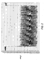
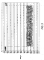
- Figures 2 and 3 show real-time ink pressure traces for un-dampened and dampened ink delivery systems.
- the ink delivery system is as shown in Figure 1 but with the air compliance chamber 70 absent.
- the average pressure during pumping is stable at about -975 mmH 2 O, but the dynamic pressure oscillates between about-600 and -1250 mmH 2 O.
- the lowest pressure of about -1250 mmH 2 O is close to the gulping point of the printhead 4 and represents a significant risk of gulping during pumping.
- the ink delivery is as shown in Figure 1 , including the air compliance chamber 70 having a volume of about 0.4 mL. From Figure 3 , it will be seen that the air compliance chamber 70 functions as a 'shock absorber' in the ink delivery system. For this dampened system, the average pressure during pumping is still stable at about -975 mmH 2 O, but the dynamic pressure oscillations are significantly reduced and vary between about -850 and -975 mmH 2 O. Hence, the lowest pressure of -975 mmH 2 O is much further from the gulping point of the printhead 4, which minimizes the risk of undesirable gulping during pumping.
- the air compliance chamber 70 may be connected to the second ink conduit 16 via a simple T-connector 72 or similar.
- the chamber 70 comprises sidewalls 74 defined by a length of tubing and a cap 76.
- the tubing defining the sidewalls 74 of the chamber 70 may be comprised of Tygoprene ® XL-60 having an internal diameter of 3.6 mm.
- the length of tubing may be adjusted to provide optimal dampening. In this example, the tubing has a length about 4 cm to provide a chamber volume of about 0.4 mL.
- a significant problem with air compliance chambers is that they are ineffective if they become filled with ink.
- the chamber sidewalls 74 may be configured to extend generally upwards to minimize the risk of ink filling the chamber 70 when the printer is tilted.
- the air compliance chamber 70 becomes ineffective or only partially effective due to ingress of ink.
- FIG. 5 there is shown the air compliance chamber 70, which has been partially filled with ink.
- the efficacy of this partially-filled chamber is reduced, because the volume of compressible air inside the chamber has been reduced.
- the printer is in its "STANDBY" mode with a negative hydrostatic ink pressure by virtue of fluidic communication between the chamber 70 and the ink container 2.
- the sidewalls 74 of the chamber 70 have a degree of air-permeability, the chamber is self-recovering, because air from atmosphere is allowed to enter the chamber by diffusing through the sidewalls.
- air entering the chamber 70 via the sidewalls 74 can displace any ink in the chamber and eventually restore the chamber to its optimum operational state, as shown in Figure 4 .
- the air compliance chamber 70 is restored to its optimum operational state within a few days (e.g. 1 to 7 days) of becoming fouled with ink.
- trapping air bubbles in the air compliance chamber 70 also aids recovery.
- the printhead 4 may comprises N ink channels (e.g. CMYK, CMYKK, CMY etc ) supplied with ink from N ink containers 2, with each of the N ink containers 2 connected to the printhead via respective first and second ink conduits 10 and 16. (Typically, N is an integer from 2 to 10). Each second conduit 16 will typically have a respective air compliance chamber 70 in fluid communication therewith.
- the printer 1 typically employs shared components in the ink delivery system, such as a multiple channel peristaltic pump 40, a multiple channel pinch valve arrangement 42 and multiple channel printhead couplings 3 and 5.
Landscapes
- Ink Jet (AREA)
Applications Claiming Priority (2)
| Application Number | Priority Date | Filing Date | Title |
|---|---|---|---|
| US201261669410P | 2012-07-09 | 2012-07-09 | |
| PCT/EP2013/064086 WO2014009233A1 (en) | 2012-07-09 | 2013-07-03 | Printer having ink delivery system with air compliance chamber |
Publications (2)
| Publication Number | Publication Date |
|---|---|
| EP2836364A1 EP2836364A1 (en) | 2015-02-18 |
| EP2836364B1 true EP2836364B1 (en) | 2015-09-09 |
Family
ID=48747546
Family Applications (1)
| Application Number | Title | Priority Date | Filing Date |
|---|---|---|---|
| EP13734384.4A Active EP2836364B1 (en) | 2012-07-09 | 2013-07-03 | Printer having ink delivery system with air compliance chamber |
Country Status (8)
| Country | Link |
|---|---|
| US (1) | US8926072B2 (zh) |
| EP (1) | EP2836364B1 (zh) |
| JP (1) | JP6335166B2 (zh) |
| KR (1) | KR20150038023A (zh) |
| CN (1) | CN104428137B (zh) |
| AU (1) | AU2013289395B2 (zh) |
| TW (1) | TWI600550B (zh) |
| WO (1) | WO2014009233A1 (zh) |
Families Citing this family (13)
| Publication number | Priority date | Publication date | Assignee | Title |
|---|---|---|---|---|
| US9272523B2 (en) * | 2014-04-02 | 2016-03-01 | Memjet Technology Ltd. | Printer configured for optimized printing |
| CN107206806B (zh) | 2015-01-29 | 2019-09-17 | 惠普发展公司,有限责任合伙企业 | 启动使用打印系统的方法及打印系统 |
| EP3147124A1 (de) * | 2015-08-13 | 2017-03-29 | Heidelberger Druckmaschinen AG | Verfahren zum dämpfen von druckspitzen in einer leitung für tinte eines tintenstrahldruckers |
| US20170087850A1 (en) * | 2015-09-25 | 2017-03-30 | Dover Europe Sàrl | Passive Meniscus Pressure Stabilization During Shutdown Of An Ink Jet Printing System |
| WO2017091406A1 (en) * | 2015-11-25 | 2017-06-01 | Videojet Technologies Inc. | Ink quality sensor and a condition monitoring system for an inkjet printer |
| JP2017154298A (ja) * | 2016-02-29 | 2017-09-07 | 東芝テック株式会社 | 液体循環装置、及び液体吐出装置 |
| CN110191809B (zh) * | 2016-12-29 | 2021-09-21 | 斯特拉塔西斯公司 | 用于打印头的压力控制系统 |
| JP6921618B2 (ja) * | 2017-05-10 | 2021-08-18 | キヤノン株式会社 | 記録装置、記録装置の制御方法、およびプログラム |
| US10369802B2 (en) * | 2017-07-10 | 2019-08-06 | Memjet Technology Limited | Ink filter with passive de-aeration |
| WO2020013799A1 (en) * | 2018-07-08 | 2020-01-16 | Hewlett-Packard Development Company, L.P. | Liquid delivery in an inkjet type dispenser |
| TWI789532B (zh) * | 2018-07-30 | 2023-01-11 | 瑞士商西克帕控股有限公司 | 用於印刷模組的墨水輸送系統和用於輸送墨水的方法 |
| JP7247637B2 (ja) | 2019-02-15 | 2023-03-29 | セイコーエプソン株式会社 | 液体噴射装置 |
| JP2020142413A (ja) | 2019-03-05 | 2020-09-10 | セイコーエプソン株式会社 | ダンパーユニット、および、液体噴射装置 |
Family Cites Families (24)
| Publication number | Priority date | Publication date | Assignee | Title |
|---|---|---|---|---|
| DE2460573A1 (de) * | 1974-12-20 | 1976-07-01 | Siemens Ag | Vorrichtung fuer tintenstrahlschreiber zur versorgung von piezoelektrisch betriebenen schreibduesen mit schreibfluessigkeit |
| JP2752466B2 (ja) | 1989-10-24 | 1998-05-18 | キヤノン株式会社 | インクタンクおよびインクジェットカートリッジならびにインクジェット装置 |
| US5047790A (en) * | 1990-01-12 | 1991-09-10 | Hewlett-Packard Company | Controlled capillary ink containment for ink-jet pens |
| US5757390A (en) * | 1992-08-12 | 1998-05-26 | Hewlett-Packard Company | Ink volume sensing and replenishing system |
| US5975686A (en) | 1994-10-31 | 1999-11-02 | Hewlett-Packard Company | Regulator for a free-ink inkjet pen |
| JPH10230623A (ja) * | 1997-02-21 | 1998-09-02 | Hitachi Koki Co Ltd | 加熱溶融形インクを用いたインクジェットプリンタの気泡除去装置およびその方法 |
| US6481837B1 (en) * | 2001-08-01 | 2002-11-19 | Benjamin Alan Askren | Ink delivery system |
| JP2004188664A (ja) * | 2002-12-09 | 2004-07-08 | Sharp Corp | インクジェットプリンタ |
| US7448739B2 (en) | 2005-12-05 | 2008-11-11 | Silverbrook Research Pty Ltd | Constant negative pressure head ink supply arrangement for inkjet printhead |
| US7431443B2 (en) | 2005-12-05 | 2008-10-07 | Silverbrook Research Pty Ltd | Ink reservoir with pressure regulating valve |
| CN101287606B (zh) * | 2006-03-03 | 2010-11-03 | 西尔弗布鲁克研究有限公司 | 脉冲阻尼射流结构 |
| JP4961971B2 (ja) * | 2006-11-25 | 2012-06-27 | コニカミノルタIj株式会社 | インクジェットヘッド |
| JP2008143073A (ja) | 2006-12-12 | 2008-06-26 | Ricoh Co Ltd | 画像形成装置及び制御方法 |
| US7794038B2 (en) * | 2006-12-18 | 2010-09-14 | Silverbrook Research Pty Ltd | Ink pressure regulator with regulator channel fluidically isolated from ink reservoir |
| US7703900B2 (en) | 2006-12-18 | 2010-04-27 | Silverbrook Research Pty Ltd | Ink pressure regulator using air bubbles drawn into ink |
| US7651184B2 (en) * | 2007-02-28 | 2010-01-26 | Brother Kogyo Kabushiki Kaisha | Liquid droplet ejecting apparatus |
| JP4905299B2 (ja) * | 2007-08-31 | 2012-03-28 | ブラザー工業株式会社 | 液体吐出装置 |
| US7984981B2 (en) * | 2008-03-03 | 2011-07-26 | Silverbrook Research Pty Ltd | Printer with ink supply system having downstream conduit loop |
| EP2496421B1 (en) | 2009-07-31 | 2015-06-24 | Memjet Technology Limited | Printing system with fixed printheads and movable vacuum platen |
| JP2011088328A (ja) * | 2009-10-21 | 2011-05-06 | Olympus Corp | インクジェット画像記録装置 |
| US20110279581A1 (en) | 2010-05-17 | 2011-11-17 | Silverbrook Research Pty Ltd | Multi-channel rotary valve for printhead |
| US8523335B2 (en) | 2010-05-17 | 2013-09-03 | Zamtec Ltd | System for venting gas at ink containers |
| CN105291592A (zh) | 2010-05-17 | 2016-02-03 | 麦捷特技术有限公司 | 具有模块化滑板的维护系统 |
| JP5621560B2 (ja) | 2010-12-03 | 2014-11-12 | 富士ゼロックス株式会社 | 緩衝装置、液体供給装置、及び液滴吐出装置 |
-
2013
- 2013-06-25 TW TW102122522A patent/TWI600550B/zh active
- 2013-06-28 US US13/931,240 patent/US8926072B2/en active Active
- 2013-07-03 EP EP13734384.4A patent/EP2836364B1/en active Active
- 2013-07-03 JP JP2015520913A patent/JP6335166B2/ja active Active
- 2013-07-03 CN CN201380036233.0A patent/CN104428137B/zh active Active
- 2013-07-03 KR KR20157003366A patent/KR20150038023A/ko not_active Application Discontinuation
- 2013-07-03 AU AU2013289395A patent/AU2013289395B2/en active Active
- 2013-07-03 WO PCT/EP2013/064086 patent/WO2014009233A1/en active Application Filing
Also Published As
| Publication number | Publication date |
|---|---|
| US20140009538A1 (en) | 2014-01-09 |
| JP2015525691A (ja) | 2015-09-07 |
| US8926072B2 (en) | 2015-01-06 |
| JP6335166B2 (ja) | 2018-05-30 |
| AU2013289395A1 (en) | 2014-12-11 |
| TW201418053A (zh) | 2014-05-16 |
| TWI600550B (zh) | 2017-10-01 |
| KR20150038023A (ko) | 2015-04-08 |
| CN104428137B (zh) | 2016-06-29 |
| CN104428137A (zh) | 2015-03-18 |
| EP2836364A1 (en) | 2015-02-18 |
| WO2014009233A1 (en) | 2014-01-16 |
| AU2013289395B2 (en) | 2015-06-04 |
Similar Documents
| Publication | Publication Date | Title |
|---|---|---|
| EP2836364B1 (en) | Printer having ink delivery system with air compliance chamber | |
| US6652080B2 (en) | Re-circulating fluid delivery system | |
| US9272523B2 (en) | Printer configured for optimized printing | |
| EP2844488B1 (en) | Printer configured for efficient air bubble removal | |
| US7926899B2 (en) | Inkjet printer having robust bubble-point ink pressure regulator | |
| US10369802B2 (en) | Ink filter with passive de-aeration | |
| JP4532831B2 (ja) | インクジェット記録装置 | |
| EP2043868B1 (en) | Ink pressure regulator with bubble point pressure regulation | |
| US8500257B2 (en) | Ink pressure regulator with liquid-retaining structure | |
| US7784925B2 (en) | Ink cartridge with pressure regulation | |
| EP2200833B1 (en) | Ink pressure regulator with improved liquid retention in regulator channel | |
| WO2015150148A1 (en) | Printer configured for optimized priming | |
| EP2094494B1 (en) | Ink pressure regulator |
Legal Events
| Date | Code | Title | Description |
|---|---|---|---|
| PUAI | Public reference made under article 153(3) epc to a published international application that has entered the european phase |
Free format text: ORIGINAL CODE: 0009012 |
|
| 17P | Request for examination filed |
Effective date: 20141114 |
|
| AK | Designated contracting states |
Kind code of ref document: A1 Designated state(s): AL AT BE BG CH CY CZ DE DK EE ES FI FR GB GR HR HU IE IS IT LI LT LU LV MC MK MT NL NO PL PT RO RS SE SI SK SM TR |
|
| AX | Request for extension of the european patent |
Extension state: BA ME |
|
| GRAP | Despatch of communication of intention to grant a patent |
Free format text: ORIGINAL CODE: EPIDOSNIGR1 |
|
| DAX | Request for extension of the european patent (deleted) | ||
| INTG | Intention to grant announced |
Effective date: 20150506 |
|
| GRAS | Grant fee paid |
Free format text: ORIGINAL CODE: EPIDOSNIGR3 |
|
| GRAA | (expected) grant |
Free format text: ORIGINAL CODE: 0009210 |
|
| AK | Designated contracting states |
Kind code of ref document: B1 Designated state(s): AL AT BE BG CH CY CZ DE DK EE ES FI FR GB GR HR HU IE IS IT LI LT LU LV MC MK MT NL NO PL PT RO RS SE SI SK SM TR |
|
| REG | Reference to a national code |
Ref country code: GB Ref legal event code: FG4D |
|
| REG | Reference to a national code |
Ref country code: AT Ref legal event code: REF Ref document number: 747793 Country of ref document: AT Kind code of ref document: T Effective date: 20150915 Ref country code: CH Ref legal event code: EP |
|
| REG | Reference to a national code |
Ref country code: IE Ref legal event code: FG4D |
|
| REG | Reference to a national code |
Ref country code: DE Ref legal event code: R096 Ref document number: 602013002959 Country of ref document: DE |
|
| REG | Reference to a national code |
Ref country code: NL Ref legal event code: MP Effective date: 20150909 |
|
| PG25 | Lapsed in a contracting state [announced via postgrant information from national office to epo] |
Ref country code: LT Free format text: LAPSE BECAUSE OF FAILURE TO SUBMIT A TRANSLATION OF THE DESCRIPTION OR TO PAY THE FEE WITHIN THE PRESCRIBED TIME-LIMIT Effective date: 20150909 Ref country code: NO Free format text: LAPSE BECAUSE OF FAILURE TO SUBMIT A TRANSLATION OF THE DESCRIPTION OR TO PAY THE FEE WITHIN THE PRESCRIBED TIME-LIMIT Effective date: 20151209 Ref country code: LV Free format text: LAPSE BECAUSE OF FAILURE TO SUBMIT A TRANSLATION OF THE DESCRIPTION OR TO PAY THE FEE WITHIN THE PRESCRIBED TIME-LIMIT Effective date: 20150909 Ref country code: GR Free format text: LAPSE BECAUSE OF FAILURE TO SUBMIT A TRANSLATION OF THE DESCRIPTION OR TO PAY THE FEE WITHIN THE PRESCRIBED TIME-LIMIT Effective date: 20151210 Ref country code: FI Free format text: LAPSE BECAUSE OF FAILURE TO SUBMIT A TRANSLATION OF THE DESCRIPTION OR TO PAY THE FEE WITHIN THE PRESCRIBED TIME-LIMIT Effective date: 20150909 |
|
| REG | Reference to a national code |
Ref country code: LT Ref legal event code: MG4D |
|
| REG | Reference to a national code |
Ref country code: AT Ref legal event code: MK05 Ref document number: 747793 Country of ref document: AT Kind code of ref document: T Effective date: 20150909 |
|
| PG25 | Lapsed in a contracting state [announced via postgrant information from national office to epo] |
Ref country code: SE Free format text: LAPSE BECAUSE OF FAILURE TO SUBMIT A TRANSLATION OF THE DESCRIPTION OR TO PAY THE FEE WITHIN THE PRESCRIBED TIME-LIMIT Effective date: 20150909 Ref country code: RS Free format text: LAPSE BECAUSE OF FAILURE TO SUBMIT A TRANSLATION OF THE DESCRIPTION OR TO PAY THE FEE WITHIN THE PRESCRIBED TIME-LIMIT Effective date: 20150909 Ref country code: HR Free format text: LAPSE BECAUSE OF FAILURE TO SUBMIT A TRANSLATION OF THE DESCRIPTION OR TO PAY THE FEE WITHIN THE PRESCRIBED TIME-LIMIT Effective date: 20150909 Ref country code: ES Free format text: LAPSE BECAUSE OF FAILURE TO SUBMIT A TRANSLATION OF THE DESCRIPTION OR TO PAY THE FEE WITHIN THE PRESCRIBED TIME-LIMIT Effective date: 20150909 |
|
| PG25 | Lapsed in a contracting state [announced via postgrant information from national office to epo] |
Ref country code: NL Free format text: LAPSE BECAUSE OF FAILURE TO SUBMIT A TRANSLATION OF THE DESCRIPTION OR TO PAY THE FEE WITHIN THE PRESCRIBED TIME-LIMIT Effective date: 20150909 |
|
| PG25 | Lapsed in a contracting state [announced via postgrant information from national office to epo] |
Ref country code: IS Free format text: LAPSE BECAUSE OF FAILURE TO SUBMIT A TRANSLATION OF THE DESCRIPTION OR TO PAY THE FEE WITHIN THE PRESCRIBED TIME-LIMIT Effective date: 20160109 Ref country code: CZ Free format text: LAPSE BECAUSE OF FAILURE TO SUBMIT A TRANSLATION OF THE DESCRIPTION OR TO PAY THE FEE WITHIN THE PRESCRIBED TIME-LIMIT Effective date: 20150909 Ref country code: IT Free format text: LAPSE BECAUSE OF FAILURE TO SUBMIT A TRANSLATION OF THE DESCRIPTION OR TO PAY THE FEE WITHIN THE PRESCRIBED TIME-LIMIT Effective date: 20150909 Ref country code: EE Free format text: LAPSE BECAUSE OF FAILURE TO SUBMIT A TRANSLATION OF THE DESCRIPTION OR TO PAY THE FEE WITHIN THE PRESCRIBED TIME-LIMIT Effective date: 20150909 Ref country code: SK Free format text: LAPSE BECAUSE OF FAILURE TO SUBMIT A TRANSLATION OF THE DESCRIPTION OR TO PAY THE FEE WITHIN THE PRESCRIBED TIME-LIMIT Effective date: 20150909 |
|
| PG25 | Lapsed in a contracting state [announced via postgrant information from national office to epo] |
Ref country code: RO Free format text: LAPSE BECAUSE OF FAILURE TO SUBMIT A TRANSLATION OF THE DESCRIPTION OR TO PAY THE FEE WITHIN THE PRESCRIBED TIME-LIMIT Effective date: 20150909 Ref country code: PL Free format text: LAPSE BECAUSE OF FAILURE TO SUBMIT A TRANSLATION OF THE DESCRIPTION OR TO PAY THE FEE WITHIN THE PRESCRIBED TIME-LIMIT Effective date: 20150909 Ref country code: PT Free format text: LAPSE BECAUSE OF FAILURE TO SUBMIT A TRANSLATION OF THE DESCRIPTION OR TO PAY THE FEE WITHIN THE PRESCRIBED TIME-LIMIT Effective date: 20160111 Ref country code: AT Free format text: LAPSE BECAUSE OF FAILURE TO SUBMIT A TRANSLATION OF THE DESCRIPTION OR TO PAY THE FEE WITHIN THE PRESCRIBED TIME-LIMIT Effective date: 20150909 |
|
| REG | Reference to a national code |
Ref country code: DE Ref legal event code: R097 Ref document number: 602013002959 Country of ref document: DE |
|
| PLBE | No opposition filed within time limit |
Free format text: ORIGINAL CODE: 0009261 |
|
| STAA | Information on the status of an ep patent application or granted ep patent |
Free format text: STATUS: NO OPPOSITION FILED WITHIN TIME LIMIT |
|
| REG | Reference to a national code |
Ref country code: FR Ref legal event code: PLFP Year of fee payment: 4 |
|
| 26N | No opposition filed |
Effective date: 20160610 |
|
| PG25 | Lapsed in a contracting state [announced via postgrant information from national office to epo] |
Ref country code: DK Free format text: LAPSE BECAUSE OF FAILURE TO SUBMIT A TRANSLATION OF THE DESCRIPTION OR TO PAY THE FEE WITHIN THE PRESCRIBED TIME-LIMIT Effective date: 20150909 Ref country code: SI Free format text: LAPSE BECAUSE OF FAILURE TO SUBMIT A TRANSLATION OF THE DESCRIPTION OR TO PAY THE FEE WITHIN THE PRESCRIBED TIME-LIMIT Effective date: 20150909 |
|
| PG25 | Lapsed in a contracting state [announced via postgrant information from national office to epo] |
Ref country code: BE Free format text: LAPSE BECAUSE OF FAILURE TO SUBMIT A TRANSLATION OF THE DESCRIPTION OR TO PAY THE FEE WITHIN THE PRESCRIBED TIME-LIMIT Effective date: 20150909 |
|
| REG | Reference to a national code |
Ref country code: CH Ref legal event code: PL |
|
| PG25 | Lapsed in a contracting state [announced via postgrant information from national office to epo] |
Ref country code: MC Free format text: LAPSE BECAUSE OF FAILURE TO SUBMIT A TRANSLATION OF THE DESCRIPTION OR TO PAY THE FEE WITHIN THE PRESCRIBED TIME-LIMIT Effective date: 20150909 |
|
| PG25 | Lapsed in a contracting state [announced via postgrant information from national office to epo] |
Ref country code: LI Free format text: LAPSE BECAUSE OF NON-PAYMENT OF DUE FEES Effective date: 20160731 Ref country code: CH Free format text: LAPSE BECAUSE OF NON-PAYMENT OF DUE FEES Effective date: 20160731 |
|
| REG | Reference to a national code |
Ref country code: FR Ref legal event code: PLFP Year of fee payment: 5 |
|
| PG25 | Lapsed in a contracting state [announced via postgrant information from national office to epo] |
Ref country code: LU Free format text: LAPSE BECAUSE OF NON-PAYMENT OF DUE FEES Effective date: 20160703 |
|
| PG25 | Lapsed in a contracting state [announced via postgrant information from national office to epo] |
Ref country code: SM Free format text: LAPSE BECAUSE OF FAILURE TO SUBMIT A TRANSLATION OF THE DESCRIPTION OR TO PAY THE FEE WITHIN THE PRESCRIBED TIME-LIMIT Effective date: 20150909 Ref country code: HU Free format text: LAPSE BECAUSE OF FAILURE TO SUBMIT A TRANSLATION OF THE DESCRIPTION OR TO PAY THE FEE WITHIN THE PRESCRIBED TIME-LIMIT; INVALID AB INITIO Effective date: 20130703 |
|
| PG25 | Lapsed in a contracting state [announced via postgrant information from national office to epo] |
Ref country code: MT Free format text: LAPSE BECAUSE OF NON-PAYMENT OF DUE FEES Effective date: 20160731 Ref country code: CY Free format text: LAPSE BECAUSE OF FAILURE TO SUBMIT A TRANSLATION OF THE DESCRIPTION OR TO PAY THE FEE WITHIN THE PRESCRIBED TIME-LIMIT Effective date: 20150909 Ref country code: MK Free format text: LAPSE BECAUSE OF FAILURE TO SUBMIT A TRANSLATION OF THE DESCRIPTION OR TO PAY THE FEE WITHIN THE PRESCRIBED TIME-LIMIT Effective date: 20150909 |
|
| REG | Reference to a national code |
Ref country code: FR Ref legal event code: PLFP Year of fee payment: 6 |
|
| PG25 | Lapsed in a contracting state [announced via postgrant information from national office to epo] |
Ref country code: BG Free format text: LAPSE BECAUSE OF FAILURE TO SUBMIT A TRANSLATION OF THE DESCRIPTION OR TO PAY THE FEE WITHIN THE PRESCRIBED TIME-LIMIT Effective date: 20150909 |
|
| PG25 | Lapsed in a contracting state [announced via postgrant information from national office to epo] |
Ref country code: AL Free format text: LAPSE BECAUSE OF FAILURE TO SUBMIT A TRANSLATION OF THE DESCRIPTION OR TO PAY THE FEE WITHIN THE PRESCRIBED TIME-LIMIT Effective date: 20150909 Ref country code: TR Free format text: LAPSE BECAUSE OF FAILURE TO SUBMIT A TRANSLATION OF THE DESCRIPTION OR TO PAY THE FEE WITHIN THE PRESCRIBED TIME-LIMIT Effective date: 20150909 |
|
| PGFP | Annual fee paid to national office [announced via postgrant information from national office to epo] |
Ref country code: IE Payment date: 20210727 Year of fee payment: 9 |
|
| P01 | Opt-out of the competence of the unified patent court (upc) registered |
Effective date: 20230419 |
|
| PG25 | Lapsed in a contracting state [announced via postgrant information from national office to epo] |
Ref country code: IE Free format text: LAPSE BECAUSE OF NON-PAYMENT OF DUE FEES Effective date: 20220703 |
|
| PGFP | Annual fee paid to national office [announced via postgrant information from national office to epo] |
Ref country code: GB Payment date: 20230727 Year of fee payment: 11 |
|
| PGFP | Annual fee paid to national office [announced via postgrant information from national office to epo] |
Ref country code: FR Payment date: 20230725 Year of fee payment: 11 Ref country code: DE Payment date: 20230727 Year of fee payment: 11 |