EP2836291B1 - A flow distributor - Google Patents
A flow distributor Download PDFInfo
- Publication number
- EP2836291B1 EP2836291B1 EP13776313.2A EP13776313A EP2836291B1 EP 2836291 B1 EP2836291 B1 EP 2836291B1 EP 13776313 A EP13776313 A EP 13776313A EP 2836291 B1 EP2836291 B1 EP 2836291B1
- Authority
- EP
- European Patent Office
- Prior art keywords
- diverter
- flow
- inlet
- housing
- outlets
- Prior art date
- Legal status (The legal status is an assumption and is not a legal conclusion. Google has not performed a legal analysis and makes no representation as to the accuracy of the status listed.)
- Active
Links
- 239000012530 fluid Substances 0.000 claims description 80
- 238000000034 method Methods 0.000 claims description 28
- 239000003638 chemical reducing agent Substances 0.000 claims description 11
- 238000004891 communication Methods 0.000 claims description 3
- 239000012071 phase Substances 0.000 description 63
- 230000008569 process Effects 0.000 description 11
- 238000002156 mixing Methods 0.000 description 10
- 239000007787 solid Substances 0.000 description 9
- 239000002002 slurry Substances 0.000 description 8
- 239000007789 gas Substances 0.000 description 5
- 239000007788 liquid Substances 0.000 description 5
- 239000000463 material Substances 0.000 description 5
- 239000000203 mixture Substances 0.000 description 5
- 230000007423 decrease Effects 0.000 description 3
- PXHVJJICTQNCMI-UHFFFAOYSA-N Nickel Chemical compound [Ni] PXHVJJICTQNCMI-UHFFFAOYSA-N 0.000 description 2
- 230000008859 change Effects 0.000 description 2
- 230000005484 gravity Effects 0.000 description 2
- 238000005552 hardfacing Methods 0.000 description 2
- 238000000265 homogenisation Methods 0.000 description 2
- 238000012986 modification Methods 0.000 description 2
- 230000004048 modification Effects 0.000 description 2
- 239000003507 refrigerant Substances 0.000 description 2
- 238000011144 upstream manufacturing Methods 0.000 description 2
- 229910001018 Cast iron Inorganic materials 0.000 description 1
- RYGMFSIKBFXOCR-UHFFFAOYSA-N Copper Chemical compound [Cu] RYGMFSIKBFXOCR-UHFFFAOYSA-N 0.000 description 1
- 229920002449 FKM Polymers 0.000 description 1
- 229910001209 Low-carbon steel Inorganic materials 0.000 description 1
- 239000004698 Polyethylene Substances 0.000 description 1
- 239000004793 Polystyrene Substances 0.000 description 1
- 229910001347 Stellite Inorganic materials 0.000 description 1
- RTAQQCXQSZGOHL-UHFFFAOYSA-N Titanium Chemical compound [Ti] RTAQQCXQSZGOHL-UHFFFAOYSA-N 0.000 description 1
- 230000001133 acceleration Effects 0.000 description 1
- 229910045601 alloy Inorganic materials 0.000 description 1
- 239000000956 alloy Substances 0.000 description 1
- 239000004411 aluminium Substances 0.000 description 1
- 229910052782 aluminium Inorganic materials 0.000 description 1
- XAGFODPZIPBFFR-UHFFFAOYSA-N aluminium Chemical compound [Al] XAGFODPZIPBFFR-UHFFFAOYSA-N 0.000 description 1
- 239000000919 ceramic Substances 0.000 description 1
- 239000003795 chemical substances by application Substances 0.000 description 1
- AHICWQREWHDHHF-UHFFFAOYSA-N chromium;cobalt;iron;manganese;methane;molybdenum;nickel;silicon;tungsten Chemical compound C.[Si].[Cr].[Mn].[Fe].[Co].[Ni].[Mo].[W] AHICWQREWHDHHF-UHFFFAOYSA-N 0.000 description 1
- 239000011248 coating agent Substances 0.000 description 1
- 229910052802 copper Inorganic materials 0.000 description 1
- 239000010949 copper Substances 0.000 description 1
- 239000006185 dispersion Substances 0.000 description 1
- 238000011143 downstream manufacturing Methods 0.000 description 1
- 229920001971 elastomer Polymers 0.000 description 1
- 229920001973 fluoroelastomer Polymers 0.000 description 1
- 239000007792 gaseous phase Substances 0.000 description 1
- 239000007791 liquid phase Substances 0.000 description 1
- 238000012423 maintenance Methods 0.000 description 1
- 239000002184 metal Substances 0.000 description 1
- 229910052751 metal Inorganic materials 0.000 description 1
- 239000007769 metal material Substances 0.000 description 1
- 150000002739 metals Chemical class 0.000 description 1
- 238000005065 mining Methods 0.000 description 1
- 229910052759 nickel Inorganic materials 0.000 description 1
- 239000002245 particle Substances 0.000 description 1
- 239000004033 plastic Substances 0.000 description 1
- 229920003023 plastic Polymers 0.000 description 1
- -1 polyethylene Polymers 0.000 description 1
- 229920000573 polyethylene Polymers 0.000 description 1
- 229920001296 polysiloxane Polymers 0.000 description 1
- 229920002223 polystyrene Polymers 0.000 description 1
- 239000004810 polytetrafluoroethylene Substances 0.000 description 1
- 229920001343 polytetrafluoroethylene Polymers 0.000 description 1
- 230000000750 progressive effect Effects 0.000 description 1
- 238000000926 separation method Methods 0.000 description 1
- 239000007790 solid phase Substances 0.000 description 1
- 229910001220 stainless steel Inorganic materials 0.000 description 1
- 239000010935 stainless steel Substances 0.000 description 1
- 239000000126 substance Substances 0.000 description 1
- 239000010936 titanium Substances 0.000 description 1
- 229910052719 titanium Inorganic materials 0.000 description 1
- 230000007704 transition Effects 0.000 description 1
Images


Classifications
-
- F—MECHANICAL ENGINEERING; LIGHTING; HEATING; WEAPONS; BLASTING
- F16—ENGINEERING ELEMENTS AND UNITS; GENERAL MEASURES FOR PRODUCING AND MAINTAINING EFFECTIVE FUNCTIONING OF MACHINES OR INSTALLATIONS; THERMAL INSULATION IN GENERAL
- F16L—PIPES; JOINTS OR FITTINGS FOR PIPES; SUPPORTS FOR PIPES, CABLES OR PROTECTIVE TUBING; MEANS FOR THERMAL INSULATION IN GENERAL
- F16L41/00—Branching pipes; Joining pipes to walls
- F16L41/02—Branch units, e.g. made in one piece, welded, riveted
- F16L41/03—Branch units, e.g. made in one piece, welded, riveted comprising junction pieces for four or more pipe members
-
- F—MECHANICAL ENGINEERING; LIGHTING; HEATING; WEAPONS; BLASTING
- F25—REFRIGERATION OR COOLING; COMBINED HEATING AND REFRIGERATION SYSTEMS; HEAT PUMP SYSTEMS; MANUFACTURE OR STORAGE OF ICE; LIQUEFACTION SOLIDIFICATION OF GASES
- F25B—REFRIGERATION MACHINES, PLANTS OR SYSTEMS; COMBINED HEATING AND REFRIGERATION SYSTEMS; HEAT PUMP SYSTEMS
- F25B41/00—Fluid-circulation arrangements
- F25B41/40—Fluid line arrangements
- F25B41/42—Arrangements for diverging or converging flows, e.g. branch lines or junctions
- F25B41/48—Arrangements for diverging or converging flows, e.g. branch lines or junctions for flow path resistance control on the downstream side of the diverging point, e.g. by an orifice
-
- B—PERFORMING OPERATIONS; TRANSPORTING
- B01—PHYSICAL OR CHEMICAL PROCESSES OR APPARATUS IN GENERAL
- B01F—MIXING, e.g. DISSOLVING, EMULSIFYING OR DISPERSING
- B01F25/00—Flow mixers; Mixers for falling materials, e.g. solid particles
- B01F25/40—Static mixers
- B01F25/42—Static mixers in which the mixing is affected by moving the components jointly in changing directions, e.g. in tubes provided with baffles or obstructions
- B01F25/43—Mixing tubes, e.g. wherein the material is moved in a radial or partly reversed direction
- B01F25/433—Mixing tubes wherein the shape of the tube influences the mixing, e.g. mixing tubes with varying cross-section or provided with inwardly extending profiles
- B01F25/4332—Mixers with a strong change of direction in the conduit for homogenizing the flow
-
- B—PERFORMING OPERATIONS; TRANSPORTING
- B01—PHYSICAL OR CHEMICAL PROCESSES OR APPARATUS IN GENERAL
- B01F—MIXING, e.g. DISSOLVING, EMULSIFYING OR DISPERSING
- B01F25/00—Flow mixers; Mixers for falling materials, e.g. solid particles
- B01F25/40—Static mixers
- B01F25/42—Static mixers in which the mixing is affected by moving the components jointly in changing directions, e.g. in tubes provided with baffles or obstructions
- B01F25/43—Mixing tubes, e.g. wherein the material is moved in a radial or partly reversed direction
- B01F25/433—Mixing tubes wherein the shape of the tube influences the mixing, e.g. mixing tubes with varying cross-section or provided with inwardly extending profiles
- B01F25/4336—Mixers with a diverging cross-section
-
- F—MECHANICAL ENGINEERING; LIGHTING; HEATING; WEAPONS; BLASTING
- F16—ENGINEERING ELEMENTS AND UNITS; GENERAL MEASURES FOR PRODUCING AND MAINTAINING EFFECTIVE FUNCTIONING OF MACHINES OR INSTALLATIONS; THERMAL INSULATION IN GENERAL
- F16L—PIPES; JOINTS OR FITTINGS FOR PIPES; SUPPORTS FOR PIPES, CABLES OR PROTECTIVE TUBING; MEANS FOR THERMAL INSULATION IN GENERAL
- F16L41/00—Branching pipes; Joining pipes to walls
- F16L41/02—Branch units, e.g. made in one piece, welded, riveted
- F16L41/021—T- or cross-pieces
-
- F—MECHANICAL ENGINEERING; LIGHTING; HEATING; WEAPONS; BLASTING
- F16—ENGINEERING ELEMENTS AND UNITS; GENERAL MEASURES FOR PRODUCING AND MAINTAINING EFFECTIVE FUNCTIONING OF MACHINES OR INSTALLATIONS; THERMAL INSULATION IN GENERAL
- F16L—PIPES; JOINTS OR FITTINGS FOR PIPES; SUPPORTS FOR PIPES, CABLES OR PROTECTIVE TUBING; MEANS FOR THERMAL INSULATION IN GENERAL
- F16L41/00—Branching pipes; Joining pipes to walls
- F16L41/02—Branch units, e.g. made in one piece, welded, riveted
- F16L41/023—Y- pieces
-
- F—MECHANICAL ENGINEERING; LIGHTING; HEATING; WEAPONS; BLASTING
- F17—STORING OR DISTRIBUTING GASES OR LIQUIDS
- F17D—PIPE-LINE SYSTEMS; PIPE-LINES
- F17D1/00—Pipe-line systems
- F17D1/005—Pipe-line systems for a two-phase gas-liquid flow
-
- F—MECHANICAL ENGINEERING; LIGHTING; HEATING; WEAPONS; BLASTING
- F25—REFRIGERATION OR COOLING; COMBINED HEATING AND REFRIGERATION SYSTEMS; HEAT PUMP SYSTEMS; MANUFACTURE OR STORAGE OF ICE; LIQUEFACTION SOLIDIFICATION OF GASES
- F25B—REFRIGERATION MACHINES, PLANTS OR SYSTEMS; COMBINED HEATING AND REFRIGERATION SYSTEMS; HEAT PUMP SYSTEMS
- F25B39/00—Evaporators; Condensers
- F25B39/02—Evaporators
- F25B39/028—Evaporators having distributing means
-
- F—MECHANICAL ENGINEERING; LIGHTING; HEATING; WEAPONS; BLASTING
- F28—HEAT EXCHANGE IN GENERAL
- F28D—HEAT-EXCHANGE APPARATUS, NOT PROVIDED FOR IN ANOTHER SUBCLASS, IN WHICH THE HEAT-EXCHANGE MEDIA DO NOT COME INTO DIRECT CONTACT
- F28D20/00—Heat storage plants or apparatus in general; Regenerative heat-exchange apparatus not covered by groups F28D17/00 or F28D19/00
- F28D2020/0065—Details, e.g. particular heat storage tanks, auxiliary members within tanks
- F28D2020/0069—Distributing arrangements; Fluid deflecting means
-
- Y—GENERAL TAGGING OF NEW TECHNOLOGICAL DEVELOPMENTS; GENERAL TAGGING OF CROSS-SECTIONAL TECHNOLOGIES SPANNING OVER SEVERAL SECTIONS OF THE IPC; TECHNICAL SUBJECTS COVERED BY FORMER USPC CROSS-REFERENCE ART COLLECTIONS [XRACs] AND DIGESTS
- Y10—TECHNICAL SUBJECTS COVERED BY FORMER USPC
- Y10T—TECHNICAL SUBJECTS COVERED BY FORMER US CLASSIFICATION
- Y10T137/00—Fluid handling
- Y10T137/0318—Processes
- Y10T137/0402—Cleaning, repairing, or assembling
-
- Y—GENERAL TAGGING OF NEW TECHNOLOGICAL DEVELOPMENTS; GENERAL TAGGING OF CROSS-SECTIONAL TECHNOLOGIES SPANNING OVER SEVERAL SECTIONS OF THE IPC; TECHNICAL SUBJECTS COVERED BY FORMER USPC CROSS-REFERENCE ART COLLECTIONS [XRACs] AND DIGESTS
- Y10—TECHNICAL SUBJECTS COVERED BY FORMER USPC
- Y10T—TECHNICAL SUBJECTS COVERED BY FORMER US CLASSIFICATION
- Y10T137/00—Fluid handling
- Y10T137/8593—Systems
- Y10T137/85938—Non-valved flow dividers
Definitions
- the present invention relates to a flow distributor for distributing a multi-phase fluid or slurry from an inlet pipe to a plurality of outlet pipes.
- process unit modules arranged in a cluster.
- the number of process unit modules arranged in the cluster can range from two (2) to as many as thirty (30) units, or possibly more.
- Such process unit modules may include, by way of example, a separator for separating a solid phase from a gaseous phase, or for separating solid particles of different sizes or different density from a liquid phase.
- Conventional flow distributors generally comprise a cylindrical chamber having a much larger cross-sectional area than the cross-sectional area of the inlet which promotes settling and clumping of solids held within the chamber of such conventional flow distributors as the multiphase fluid or slurry travels from the inlet to the plurality of outlets.
- US 2010/313585 discloses a fluid expansion-distribution assembly for mixing and distributing refrigerant. However, that assembly throttles the refrigerant fluid.
- WO 03/073021 discloses a flow distribution system according to the preamble of claim 1 and a method of distributing according to the preamble of claim 17.
- the flow rate of the multi-phase fluid stream varies it passes through the flow channel whereby turbulent mixing of the multi-phase fluid stream in the inner chamber is encouraged.
- the first chamber portion has a constant cross-sectional area and the second chamber portion has a constant cross-sectional area that is greater than the cross-sectional area of the first chamber portion.
- the first chamber portion is frustoconical.
- the hollow housing is symmetrical about its central longitudinal axis. In one form, the central longitudinal axis of the housing is coincident with or parallel to the central longitudinal axis of the inlet.
- the flow distribution system further comprises a mounting means for mounting the flow diverter to the housing or to an access cover used for closing a first end of the housing.
- the mounting means is actuated to raise or lower the position of the flow diverter to adjust the distance between the flow diverter and the inlet.
- the mounting means is actuated to move the flow diverter laterally or radially relative to the central longitudinal axis of the housing whereby the central longitudinal axis of the flow diverter is offset from the central longitudinal axis of the housing.
- the plurality of outlets are radially arranged around the perimeter or circumference of the housing wherein the multi-phase fluid stream is diverted through an angle of (i) at least 45 to 135, (ii) at least 60 to 120, or (iii) at least 90 degrees, as it travels from the inlet to the plurality of outlets.
- the flow diverter or a portion of the flow diverter is frustoconical, cylindrical, domed, semi-ovaloid, semi-spherical or egg-shaped.
- the flow diverter includes a disc-shaped third diverter portion arranged between the first diverter portion and the second diverter portion and wherein the widest cross-sectional area of the third diverter portion is greater than the cross-sectional area of the first and second diverter portions.
- the third diverter portion is positioned in the first chamber portion or the second chamber portion.
- the flow diverter includes a diverter tip portion.
- each outlet is evenly spaced apart around the perimeter or circumference of the housing so that each of the outlets is equidistant from the inlet and equidistant from each other outlet.
- each outlet is a concentric or eccentric reducer.
- the flow distribution system has a first orientation whereby the inlet is closer to the ground than the plurality of outlets such that the multi-phase fluid stream travels vertically upwardly through the inner chamber.
- the flow distribution system has a second orientation whereby the plurality of outlets is closer to the ground than inlet with the result that the multi-phase fluid stream travels downwardly through the inner chamber.
- the flow diverter has a first diverter portion positioned within the first chamber portion and a second diverter portion positioned within the second chamber portion, wherein, the cross-sectional area of the flow channel is smaller in a first chamber portion than in a second chamber portion generating a region of low or negative pressure adjacent to the second diverter portion,
- the method further comprises the step of mounting the flow diverter to the housing or to an access cover used for closing a first end of the housing.
- the method further comprises the step of actuating the mounting means to raise or lower the position of the flow diverter to adjust the distance between the flow diverter and the inlet.
- the method further comprises the step of actuating the mounting means to move the flow diverter laterally or radially relative to the central longitudinal axis of the housing whereby the central longitudinal axis of the flow diverter is offset from the central longitudinal axis of the housing.
- the method further comprises the step of arranging the flow distribution system in a first orientation whereby the inlet is closer to the ground than the plurality of outlets such that the multi-phase fluid stream travels vertically upwardly through the inner chamber.
- the method further comprises the step of arranging the flow distribution system in a second orientation whereby the plurality of outlets is closer to the ground than inlet with the result that the multi-phase fluid stream travels downwardly through the inner chamber.
- Ranges may be expressed herein as from “about” or “approximately” one particular value and/or to “about” or “approximately” another particular value. When such a range is expressed, another embodiment includes from the one particular value and/or to the other particular value. Similarly, when values are expressed as approximations, by use of the antecedent "about,” it will be understood that the particular value forms another embodiment.
- the term 'fluid' is used to describe a gas or a liquid.
- the term 'multi-phase fluid' is used to refer to a mixture of a solids phase with a gas or a solids phase with a liquid.
- the term 'multi-phase fluid' may also refer to a mixture of a liquid with a gas or a mixture of a solids phase with a gas and a liquid.
- the term 'slurry' refers to an insoluble solids phase mixed with a fluid or gas. A slurry is thus one example of a multi-phase fluid.
- the term 'non-planar' refers to a three-dimensional object which has a width, a height and length as opposed to planar objects which substantially occupy a single geometric plane.
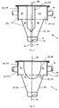
- the system 10 includes an inlet 12 for receiving a multi-phase fluid stream from an inlet pipe 14 and a plurality of outlets 16 each for delivering a portion of the multi-phase fluid stream to a respective outlet pipe 18.
- the system 10 includes a hollow housing 20 forming an inner chamber 22 in fluid communication with the inlet 12 and the plurality of outlets 16.
- a non-planar flow diverter 24 is positioned within the chamber 22 so as to define a flow channel 26 of varying cross-sectional area for accelerating or decelerating the multi-phase fluid stream as it passes through the inner chamber to encourage turbulent mixing within the multi-phase fluid stream as it passes from the inlet to the plurality of outlets.
- the flow diverter 24 When the multi-phase liquid stream encounters the flow diverter 24, the flow is diverted around the flow diverter 24 and into the flow channel 26.
- the primary goal of generating turbulence is to ensure that the phases present within each portion of the multi-phase fluid stream are as homogeneous as possible as they enter each outlet.
- the cross-sectional area of the flow channel 26 as measured in a plane orthogonal to the longitudinal axis 28 of the housing 20 varies to generate areas of differential pressure within the inner chamber that encourage mixing and thus homogenisation of the multi-phase fluid as it passes through the flow distribution system.
- the characteristics of the portion of the multi-phase fluid stream delivered to each outlet are more uniform, leading to improvements in performance of the process unit modules (not shown) that are connected to each respective outlet pipe.
- the multi-phase fluid stream is pre-homogenised upstream of the inlet.
- the inner chamber 22 has a first chamber portion 30 that is closer to the inlet 12 than the plurality of outlets 16 and a second chamber portion 32 adjacent to the plurality of outlets 16.
- the first chamber portion 30 has a cross-sectional area as measured within the flow channel 26 that is less than the cross-sectional area of the second chamber portion 32 as measured within the flow channel 26.
- the non-planar flow diverter 24 has a constant cross-sectional area and thus the flow channel of varying cross-sectional area 26 is created by varying the cross-sectional areas of the first and second chamber portions 30 and 32, respectively to generate mixing of the multi-phase fluid stream as it passes through the inner chamber 22 and is diverted by the flow diverter 24.
- the first chamber portion 30 has a first cross-sectional area that remains constant and the second chamber portion 32 has a second larger cross-sectional area that also remains constant.
- the flow velocity of the multi-phase fluid stream initially drops when it enters the first chamber portion 30 due to the cross-sectional area of the first chamber portion 30 being greater than the cross-sectional area of the inlet 12.
- the first chamber portion 30 is frustoconical with the result that the first cross-sectional area varies progressively as measured in a plane that is orthogonal to the central longitudinal axis 28 of the housing 20.
- the second chamber portion 32 has a second cross-sectional area that remains constant.
- the hollow housing 20 has a cylindrical footprint as illustrated in Figure 1
- the first and second chamber portions 30 and 32 respectively are both cylindrical.
- the hollow housing could equally have a rectangular, square, triangular, hexagonal, octagonal, oval, or polygonal footprint.
- the hollow housing 20 is symmetrical about the central longitudinal axis 28 and the central longitudinal axis 28 is coincident with the central longitudinal axis 34 of the inlet 12.
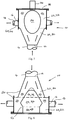
- An access cover 38 is provided to close a first end 40 of the hollow housing 20 while the inlet 12 is provided at a second opposite end 42 of the housing 20.
- the flow diverter 24 is mechanically coupled to the access cover 38 using a mounting means 44, which advantageously allows the flow diverter to be retrofitted to an existing flow distributor if desired.
- the flow diverter 24 is secured to the access cover 38 by a mounting means 44 comprising three bolts secured by nuts and fluid seals. It is to be understood that other suitable mounting means may equally be used.
- the non-planar flow diverter 24 has a first diverter portion 46 positioned within the first chamber portion 30 and a second diverter portion 48 positioned within the second chamber portion 32. It is readily apparent from Figures 1 and 2 that the cross-sectional area of the flow channel 26 is smaller in the first chamber portion 30 than in the second chamber portion 32 generating a region of low or negative pressure adjacent to the second diverter portion 48 that encourages mixing of the multiphase fluid stream in an area of the flow channel that is adjacent to the plurality of outlets 16.
- the flow diverter is positioned within the inner chamber so as to define a flow channel of varying cross-sectional area as measured in a plane orthogonal to the longitudinal central axis of the housing so as to cause changes in one or more of the velocity, pressure or flow rate of the multiphase fluid stream as it passes through the flow channel.
- the first diverter portion 46 is frustoconical and the second diverter portion 48 is cylindrical.
- the first diverter portion is domed, semi-ovaloid or semi-spherical and the second diverter portion is cylindrical.
- the flow diverter 24 is an egg shape. In all of these embodiments, the flow diverter is three-dimensional so that the flow channel 26 has a varying cross-sectional area as measured in a plane orthogonal to the central longitudinal axis of the housing.
- the flow diverter 24 has a first diverter portion 46 positioned within the first chamber portion 30 and a second diverter portion 48 positioned within the second chamber portion 32.
- the first diverter portion 46 is frustoconical and the second diverter portion 48 is cylindrical.
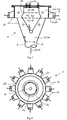
- the flow diverter 24 is further provided with a disc-shaped third diverter portion 52 arranged between the first diverter portion 46 and the second diverter portion 48.
- the widest cross-sectional area of the third diverter portion 52 is greater than the cross-sectional area of the first and second diverter portions.
- the third diverter portion 52 may be positioned within the first chamber portion 30 as illustrated in Figure 9 or within the second chamber portion 32 as illustrate in Figures 6 and 7 .
- the purpose of providing the wider third diverter portion 52 is to generate a region of low or negative pressure in an area 53 adjacent to and downstream of the second diverter portion 48 to encourage mixing of the multiphase fluid stream in an area of the flow channel 46 that is in proximity of or adjacent to the plurality of outlets 16.
- the flow diverter is positioned within the inner chamber so as to define a flow channel of varying cross-sectional area as measured in a plane orthogonal to the longitudinal central axis of the housing.
- the flow diverter 24 is further provided with a diverter tip portion 54 to mitigate the risk of damage to the flow diverter from wear associated with the impact of the multi-phase feed stream when it first encounters the flow diverter 24 in use.
- the tip portion may be fabricated from a wear resistant material and be removable for replacement to extend the life of the flow diverter if desired.
- the velocity of the multi-phase feed stream is highest towards the central longitudinal axis 34 of the inlet 12 where frictional losses due to contact between the multi-phase fluid stream and the internal walls of the inlet pipe 14 are lowest.
- some or all of the external surfaces of the flow diverter may be coated in a wear resistant material.
- the first diverter portion 46 is frustoconical and the second diverter portion 48 is cylindrical as stated above.
- the first chamber portion 30 may also be frustoconical such that the cross-sectional area of the first chamber portion 30 progressively varies as measured in a plane that is orthogonal to the central longitudinal axis 28 of the housing 20, while the second chamber portion 32 has a second cross-sectional area that remains constant.
- the angle ( ⁇ ) of the first chamber portion 30 as measured parallel to the central longitudinal axis 28 of the housing 20 is different to the angle ( ⁇ ) of the first diverter portion 46 as measured parallel to the central longitudinal axis 28 of the housing 20.
- the cross-sectional area of the flow channel 26 varies as the multi-phase fluid stream travels from the inlet 12 to the plurality of outlets 16. It is to be understood that if the angles ⁇ and ⁇ are the same then the cross-sectional area of the flow channel will remain constant as the multi-phase fluid stream passes the first diverter portion 46. However, the velocity of the multi-phase fluid stream will decrease due to higher frictional losses associated with contact that occurs between the multi-phase fluids stream and the interior surfaces of the flow diverter 24 and housing 20.
- the flow diverter must be dimensioned relative to the housing in such a manner as to ensure that the cross-sectional area of the flow channel so defined has a varying cross-sectional area as measure in a plane that is orthogonal to the central longitudinal axis 28 of the housing 20 to homogenise the multi-phase fluid stream before a portion of the multi-phase fluid stream is allowed to enter an outlet.
- each outlet 16 is evenly spaced apart around the perimeter or circumference of the housing 20 as shown in Figures 8 and 10 .
- each of the outlets 16 is equidistant from the inlet 12 and equidistant from each other outlet.
- the number of outlets may vary depending on the duty required to be performed by the flow distribution system.
- the plurality of outlets may be in the range of 2 to 30 outlets.
- the flow distribution system includes twelve outlets whilst in the embodiment illustrated in Figure 10 , the flow distribution system includes only six outlets. It is to be understood that the number of outlets may be odd instead of even and there is no requirement for the outlets to be equidistant from each other.
- one or more of the plurality of outlets may be sealed or blocked temporarily, for example, due to maintenance of a downstream process unit module or permanently, for example, to accommodate subsequent optional expansion.
- half of the outlets may be used to serve a first bank of process unit modules while the remaining outlets may be used to serve a second bank of process unit modules.
- the position of the flow diverter 24 within the inner chamber 20 is controllable to allow movement parallel to or traverse to the central longitudinal axis 28 of the housing 20 to adjust the cross-sectional area of the flow channel 26 to compensate for situations in which one or more of the outlets is permanently or temporarily sealed or blocked in use.
- the mounting means 44 is actuated to allow the flow diverter 24 to be raised or lowered to adjust the distance between the first diverter portion 46 and the inlet 12.
- the mounting means 44 is actuated to move the flow diverter 24 laterally or radially relative to the central longitudinal axis 28 of the housing 20 whereby the central longitudinal axis 60 of the flow diverter 24 is offset from the central longitudinal axis 28 as illustrated in Figure 3 .
- the position of the flow diverter 24 may equally be adjusted to provide a more even distribution to the flow of portions of the multi-phase fluid stream to a plurality of outlets 16 in a flow distribution system that has outlets which are not equidistant.
- the central longitudinal axis 34 of the inlet 12 is arranged parallel to the longitudinal axis 28 of the housing 20.
- the central longitudinal axis 28 of the housing is coincident with the central longitudinal axis of the inlet 12. This arrangement is advantageously used to avoid generation of a centrifugal force that would otherwise be generated if the inlet pipe were arranged tangentially. A centrifugal force would encourage separation of denser phases from lighter phases within the multiphase fluid stream.
- the multiphase fluid stream passes through the flow channel 22 under the influence of gravity with changes in fluid flow rates and pressures being controlled by way of the shape and positioning of the non-planar fluid diverter 24.
- the inlet 12 is arranged to lie parallel to the longitudinal axis 28 of the housing 20, the plurality of outlets 16 for delivering a portion of the multi-phase fluid stream to each the respective outlet pipes 18 are radially arranged around the perimeter or circumference of the housing 20.
- the multi-phase fluid stream is diverted through an angle of at least 45 to 135, at least 60 to 120 or at least 90 degrees as it travels from the inlet to the plurality of outlets.
- homogenisation of the multi-phase fluid stream is further encouraged in an area that is adjacent to the plurality of outlets 16 due to the change of direction of the flow of each portion of the multi-phase fluid stream through an angle of at least 90 degrees as it enters each of the plurality of outlets.
- each outlet 16 has a constant cross-sectional area.
- each outlet is in the form of a reducer 62 arranged to encourage progressive acceleration of the portion of the multi-phase fluid stream that enters each outlet.
- a reducer is a fitting that has different diameters at each opening and transitions from one diameter to the other, generally in a linear fashion.
- the reducer is a concentric reducer 64.
- a concentric reducer has different diameters at each opening and the centreline of the smaller opening coincides with the centreline of the larger opening.
- the reducer is an eccentric reducer 66.
- An eccentric reducer has different diameters at each opening and the centreline of the smaller opening is offset from the centreline of the larger opening.
- the flow distribution system 10 is shown in a first orientation whereby the inlet 12 is closer to the ground than the plurality of outlets 16 with the result that the multi-phase fluid stream travels vertically upwardly through the inner chamber 20.
- the flow distribution system 10 is shown in a second orientation whereby the plurality of outlets 16 is closer to the ground than inlet 12 with the result that the multi-phase fluid stream travels downwardly through the inner chamber 20.
- the function of the flow diverter 24 remains the same for both the first and second orientations.
- the flow distribution system 10 of the present invention can be provided in either the first or the second orientation for any embodiment.
- a multi-phase fluid stream flowing through the inlet pipe 14 is directed via the inlet 12 into the inner chamber 22. It is preferred, but not essential that the multi-phase fluids stream is premixed or homogenised upstream of the inlet 12. As the multi-phase fluid enters the first chamber portion, the flow velocity decreases because the first chamber portion has a larger cross-sectional area than the cross-sectional area of the inlet.
- the multiphase fluid stream is then diverted around the flow diverter such that it enters the flow channel.
- the flow diverter causes the multi-phase fluid stream to change direction, which causes turbulence and thus mixing of the multi-phase fluid stream. Additional mixing of the multi-phase fluid stream is encouraged by varying the effective cross-sectional area of the flow channel as measured in a plane orthogonal to the central longitudinal axis of the housing.
- the flow diverter is provided with a second portion adjacent to the plurality of outlets which second portion has a smaller cross-sectional area than a first portion of the flow diverter that is closer to the inlet. This generates an area of lower or negative pressure that encourages turbulent mixing of the multi-phase fluid stream.
- the decrease in cross-sectional area will increase the fluid flow velocity entering each outlet pipe. The result is a more consistent distribution of solids within each portion of the multi-phase fluid stream that is received at each outlet.
- the flow diverter can be made or lined with any suitable material - such as polymeric materials, such as PVC, PTFE, a fluroelastomer (such as a fluoroelastomer that is commercially available under the commercial trademark VITON), rubber, silicone, polyethylene, or polystyrene; or metal materials such as aluminium, nickel, copper, or titanium or their alloys, cast iron, mild steel or stainless steel.
- a suitable material such as polymeric materials, such as PVC, PTFE, a fluroelastomer (such as a fluoroelastomer that is commercially available under the commercial trademark VITON), rubber, silicone, polyethylene, or polystyrene; or metal materials such as aluminium, nickel, copper, or titanium or their alloys, cast iron, mild steel or stainless steel.
- the external surface of the flow diverter may be lined with a hardfacing composition, such as STELLITE or CERAMIC.
- the housing can be made from any suitable material - usually metals, or plastics,
- the flow diverter may be provided with a dispersion nozzle in the tip portion, such that an agent, such as for example a flocculent or coating agent, may be dispersed into the multi-phase fluid stream. All such modifications and variations are intended to fall within the scope of the present invention, as it is defined by the appended claims.
Landscapes
- Engineering & Computer Science (AREA)
- General Engineering & Computer Science (AREA)
- Chemical & Material Sciences (AREA)
- Mechanical Engineering (AREA)
- Dispersion Chemistry (AREA)
- Chemical Kinetics & Catalysis (AREA)
- Physics & Mathematics (AREA)
- Thermal Sciences (AREA)
- Feeding, Discharge, Calcimining, Fusing, And Gas-Generation Devices (AREA)
- Physical Or Chemical Processes And Apparatus (AREA)
Description
- The present invention relates to a flow distributor for distributing a multi-phase fluid or slurry from an inlet pipe to a plurality of outlet pipes.
- It is common in mining, energy, chemical and related industries to process a multi-phase fluid stream or a slurry. It is often convenient and/or efficient to process the multi-phase fluid stream or slurry using a plurality of process unit modules arranged in a cluster. The number of process unit modules arranged in the cluster can range from two (2) to as many as thirty (30) units, or possibly more. Such process unit modules may include, by way of example, a separator for separating a solid phase from a gaseous phase, or for separating solid particles of different sizes or different density from a liquid phase.
- It is known in the art to use conventional flow distributors having an inlet arranged to receive an inlet stream of fluid from a common pipeline and a plurality of outlets for delivering a portion of the fluid to each of the plurality of process unit modules arranged in a given cluster. However, problems can arise when the inlet stream is a multi-phase stream or slurry, because the solids phase separates into layers under the influence of gravity leading to a disproportional loading of the solids phase flow to each of the plurality of outlets, therefore reducing the efficiency of the process unit modules in the cluster and increased wear on the internal walls of the flow distributor. The inlet stream may be pulsing which can lead uneven flow to each outlet leading to loss of efficiency of the process unit modules receiving the multi-phase fluid or slurry. Conventional flow distributors generally comprise a cylindrical chamber having a much larger cross-sectional area than the cross-sectional area of the inlet which promotes settling and clumping of solids held within the chamber of such conventional flow distributors as the multiphase fluid or slurry travels from the inlet to the plurality of outlets.
- It is an object of the present invention to at least partially overcome the abovementioned problems associated with the prior art, or provide an alternative thereto.
-
US 2010/313585 (Parker Christian et al. ) discloses a fluid expansion-distribution assembly for mixing and distributing refrigerant. However, that assembly throttles the refrigerant fluid. -
WO 03/073021 (Huelle et al. claim 1 and a method of distributing according to the preamble of claim 17. - According to a first aspect of the present invention there is provided a flow distribution system according to
claim 1. - Using this arrangement, the flow rate of the multi-phase fluid stream varies it passes through the flow channel whereby turbulent mixing of the multi-phase fluid stream in the inner chamber is encouraged.
- In one form, the first chamber portion has a constant cross-sectional area and the second chamber portion has a constant cross-sectional area that is greater than the cross-sectional area of the first chamber portion. In one form, the first chamber portion is frustoconical. In one form, the hollow housing is symmetrical about its central longitudinal axis. In one form, the central longitudinal axis of the housing is coincident with or parallel to the central longitudinal axis of the inlet.
- In one form, the flow distribution system further comprises a mounting means for mounting the flow diverter to the housing or to an access cover used for closing a first end of the housing. In one form, the mounting means is actuated to raise or lower the position of the flow diverter to adjust the distance between the flow diverter and the inlet. In one form, the mounting means is actuated to move the flow diverter laterally or radially relative to the central longitudinal axis of the housing whereby the central longitudinal axis of the flow diverter is offset from the central longitudinal axis of the housing. The plurality of outlets are radially arranged around the perimeter or circumference of the housing wherein the multi-phase fluid stream is diverted through an angle of (i) at least 45 to 135, (ii) at least 60 to 120, or (iii) at least 90 degrees, as it travels from the inlet to the plurality of outlets.
- In one form, the flow diverter or a portion of the flow diverter is frustoconical, cylindrical, domed, semi-ovaloid, semi-spherical or egg-shaped. In one form, the flow diverter includes a disc-shaped third diverter portion arranged between the first diverter portion and the second diverter portion and wherein the widest cross-sectional area of the third diverter portion is greater than the cross-sectional area of the first and second diverter portions. In one form, the third diverter portion is positioned in the first chamber portion or the second chamber portion. In one form, the flow diverter includes a diverter tip portion.
- In one form, each outlet is evenly spaced apart around the perimeter or circumference of the housing so that each of the outlets is equidistant from the inlet and equidistant from each other outlet. In one form, each outlet is a concentric or eccentric reducer.
- In one form, the flow distribution system has a first orientation whereby the inlet is closer to the ground than the plurality of outlets such that the multi-phase fluid stream travels vertically upwardly through the inner chamber. Alternatively, the flow distribution system has a second orientation whereby the plurality of outlets is closer to the ground than inlet with the result that the multi-phase fluid stream travels downwardly through the inner chamber.
- According to a second aspect of the present invention there is provided a method of distributing a multi-phase fluid flow according to claim 17.
- In one form, the flow diverter has a first diverter portion positioned within the first chamber portion and a second diverter portion positioned within the second chamber portion, wherein, the cross-sectional area of the flow channel is smaller in a first chamber portion than in a second chamber portion generating a region of low or negative pressure adjacent to the second diverter portion, In one form, the method further comprises the step of mounting the flow diverter to the housing or to an access cover used for closing a first end of the housing. In one form, the method further comprises the step of actuating the mounting means to raise or lower the position of the flow diverter to adjust the distance between the flow diverter and the inlet. In one form, the method further comprises the step of actuating the mounting means to move the flow diverter laterally or radially relative to the central longitudinal axis of the housing whereby the central longitudinal axis of the flow diverter is offset from the central longitudinal axis of the housing.
- In one form, the method further comprises the step of arranging the flow distribution system in a first orientation whereby the inlet is closer to the ground than the plurality of outlets such that the multi-phase fluid stream travels vertically upwardly through the inner chamber. Alternatively, in one form, the method further comprises the step of arranging the flow distribution system in a second orientation whereby the plurality of outlets is closer to the ground than inlet with the result that the multi-phase fluid stream travels downwardly through the inner chamber.
- In order to provide a better understanding of the present invention embodiments will now be described, by way of example only, with reference to the accompanying drawings, for which like reference numerals refer to like parts, in which:
-
Figure 1 is a cross-sectional schematic side elevation of a distributor according to an embodiment of the present invention; -
Figure 2 is a cross-sectional schematic side elevation of an alternative embodiment of a distributor according to the present invention; -
Figure 3 is a cross-sectional schematic side elevation of an alternative embodiment of a distributor according to the present invention; -
Figure 4 is a cross-sectional schematic side elevation of an alternative embodiment of a distributor according to the present invention; -
Figure 5 is a cross-sectional schematic side elevation of an alternative embodiment of a distributor according to the present invention; -
Figure 6 is a cross-sectional schematic side elevation of an alternative embodiment of a distributor according to the present invention; -
Figure 7 is a cross-sectional schematic side elevation of an alternative embodiment of a distributor according to the present invention; -
Figure 8 is a cross-sectional schematic plan view of the distributor ofFigure 7 ; -
Figure 9 is a cross-sectional schematic side elevation of an alternative embodiment of a distributor according to the present invention; and, -
Figure 10 is a cross-sectional schematic plan view of the distributor ofFigure 9 . - The present invention may be understood more readily by reference to the following detailed description of the invention taken in connection with the accompanying drawing figures, which form a part of this disclosure. It is to be understood that this invention is not limited to the specific devices, methods, conditions or parameters described and/or shown herein, and that the terminology used herein is for the purpose of describing particular embodiments by way of example only and is not intended to be limiting of the claimed invention. Also, as used in the specification including the appended claims, the singular forms "a," "an," and "the" include the plural, and reference to a particular numerical value includes at least that particular value, unless the context clearly dictates otherwise. Ranges may be expressed herein as from "about" or "approximately" one particular value and/or to "about" or "approximately" another particular value. When such a range is expressed, another embodiment includes from the one particular value and/or to the other particular value. Similarly, when values are expressed as approximations, by use of the antecedent "about," it will be understood that the particular value forms another embodiment.
- Throughout this specification, the term 'fluid' is used to describe a gas or a liquid. The term 'multi-phase fluid' is used to refer to a mixture of a solids phase with a gas or a solids phase with a liquid. The term 'multi-phase fluid' may also refer to a mixture of a liquid with a gas or a mixture of a solids phase with a gas and a liquid. The term 'slurry' refers to an insoluble solids phase mixed with a fluid or gas. A slurry is thus one example of a multi-phase fluid. The term 'non-planar' refers to a three-dimensional object which has a width, a height and length as opposed to planar objects which substantially occupy a single geometric plane.
A first embodiment of a flow distribution system for homogenizadon of a multi-phase fluid stream is now described with reference to Figure in which the flow distribution system is generally designated by thereference numeral 10. Thesystem 10 includes aninlet 12 for receiving a multi-phase fluid stream from aninlet pipe 14 and a plurality ofoutlets 16 each for delivering a portion of the multi-phase fluid stream to arespective outlet pipe 18. Thesystem 10 includes ahollow housing 20 forming aninner chamber 22 in fluid communication with theinlet 12 and the plurality ofoutlets 16. Anon-planar flow diverter 24 is positioned within thechamber 22 so as to define aflow channel 26 of varying cross-sectional area for accelerating or decelerating the multi-phase fluid stream as it passes through the inner chamber to encourage turbulent mixing within the multi-phase fluid stream as it passes from the inlet to the plurality of outlets. When the multi-phase liquid stream encounters theflow diverter 24, the flow is diverted around theflow diverter 24 and into theflow channel 26. Using the method and system of the present invention, the primary goal of generating turbulence is to ensure that the phases present within each portion of the multi-phase fluid stream are as homogeneous as possible as they enter each outlet. The cross-sectional area of theflow channel 26 as measured in a plane orthogonal to thelongitudinal axis 28 of thehousing 20 varies to generate areas of differential pressure within the inner chamber that encourage mixing and thus homogenisation of the multi-phase fluid as it passes through the flow distribution system. In this way, the characteristics of the portion of the multi-phase fluid stream delivered to each outlet are more uniform, leading to improvements in performance of the process unit modules (not shown) that are connected to each respective outlet pipe. For best results, the multi-phase fluid stream is pre-homogenised upstream of the inlet. - With reference to
Figure 1 , theinner chamber 22 has a first chamber portion 30 that is closer to theinlet 12 than the plurality ofoutlets 16 and a second chamber portion 32 adjacent to the plurality ofoutlets 16. The first chamber portion 30 has a cross-sectional area as measured within theflow channel 26 that is less than the cross-sectional area of the second chamber portion 32 as measured within theflow channel 26. In the embodiments illustrated inFigures 1 and 2 , thenon-planar flow diverter 24 has a constant cross-sectional area and thus the flow channel of varyingcross-sectional area 26 is created by varying the cross-sectional areas of the first and second chamber portions 30 and 32, respectively to generate mixing of the multi-phase fluid stream as it passes through theinner chamber 22 and is diverted by theflow diverter 24. InFigure 1 , the first chamber portion 30 has a first cross-sectional area that remains constant and the second chamber portion 32 has a second larger cross-sectional area that also remains constant. The flow velocity of the multi-phase fluid stream initially drops when it enters the first chamber portion 30 due to the cross-sectional area of the first chamber portion 30 being greater than the cross-sectional area of theinlet 12. In an alternative embodiment illustrated inFigure 2 , the first chamber portion 30 is frustoconical with the result that the first cross-sectional area varies progressively as measured in a plane that is orthogonal to the centrallongitudinal axis 28 of thehousing 20. The second chamber portion 32 has a second cross-sectional area that remains constant. - When the
hollow housing 20 has a cylindrical footprint as illustrated inFigure 1 , the first and second chamber portions 30 and 32, respectively are both cylindrical. The hollow housing could equally have a rectangular, square, triangular, hexagonal, octagonal, oval, or polygonal footprint. For best results, thehollow housing 20 is symmetrical about the centrallongitudinal axis 28 and the centrallongitudinal axis 28 is coincident with the centrallongitudinal axis 34 of theinlet 12. - An access cover 38 is provided to close a
first end 40 of thehollow housing 20 while theinlet 12 is provided at a second opposite end 42 of thehousing 20. Theflow diverter 24 is mechanically coupled to theaccess cover 38 using a mounting means 44, which advantageously allows the flow diverter to be retrofitted to an existing flow distributor if desired. In the embodiment illustrated inFigure 7 , theflow diverter 24 is secured to theaccess cover 38 by a mounting means 44 comprising three bolts secured by nuts and fluid seals. It is to be understood that other suitable mounting means may equally be used. - In the embodiments illustrated in
Figures 1 and 2 , thenon-planar flow diverter 24 has afirst diverter portion 46 positioned within the first chamber portion 30 and a second diverter portion 48 positioned within the second chamber portion 32. It is readily apparent fromFigures 1 and 2 that the cross-sectional area of theflow channel 26 is smaller in the first chamber portion 30 than in the second chamber portion 32 generating a region of low or negative pressure adjacent to the second diverter portion 48 that encourages mixing of the multiphase fluid stream in an area of the flow channel that is adjacent to the plurality ofoutlets 16. In this way, the flow diverter is positioned within the inner chamber so as to define a flow channel of varying cross-sectional area as measured in a plane orthogonal to the longitudinal central axis of the housing so as to cause changes in one or more of the velocity, pressure or flow rate of the multiphase fluid stream as it passes through the flow channel. - In an alternative embodiment illustrated in
Figure 3 , thefirst diverter portion 46 is frustoconical and the second diverter portion 48 is cylindrical. In another alternative embodiment illustrated inFigure 4 , the first diverter portion is domed, semi-ovaloid or semi-spherical and the second diverter portion is cylindrical. In yet another alternative embodiment illustrated inFigure 5 , theflow diverter 24 is an egg shape. In all of these embodiments, the flow diverter is three-dimensional so that theflow channel 26 has a varying cross-sectional area as measured in a plane orthogonal to the central longitudinal axis of the housing. - In the embodiments illustrated in
Figures 6 ,7 and9 , theflow diverter 24 has afirst diverter portion 46 positioned within the first chamber portion 30 and a second diverter portion 48 positioned within the second chamber portion 32. In each of these embodiments, thefirst diverter portion 46 is frustoconical and the second diverter portion 48 is cylindrical. Theflow diverter 24 is further provided with a disc-shapedthird diverter portion 52 arranged between thefirst diverter portion 46 and the second diverter portion 48. The widest cross-sectional area of thethird diverter portion 52 is greater than the cross-sectional area of the first and second diverter portions. Thethird diverter portion 52 may be positioned within the first chamber portion 30 as illustrated inFigure 9 or within the second chamber portion 32 as illustrate inFigures 6 and7 . The purpose of providing the widerthird diverter portion 52 is to generate a region of low or negative pressure in anarea 53 adjacent to and downstream of the second diverter portion 48 to encourage mixing of the multiphase fluid stream in an area of theflow channel 46 that is in proximity of or adjacent to the plurality ofoutlets 16. As with all other embodiments, the flow diverter is positioned within the inner chamber so as to define a flow channel of varying cross-sectional area as measured in a plane orthogonal to the longitudinal central axis of the housing. - In the embodiment illustrated in
Figure 7 , theflow diverter 24 is further provided with adiverter tip portion 54 to mitigate the risk of damage to the flow diverter from wear associated with the impact of the multi-phase feed stream when it first encounters theflow diverter 24 in use. The tip portion may be fabricated from a wear resistant material and be removable for replacement to extend the life of the flow diverter if desired. In this regard, the velocity of the multi-phase feed stream is highest towards the centrallongitudinal axis 34 of theinlet 12 where frictional losses due to contact between the multi-phase fluid stream and the internal walls of theinlet pipe 14 are lowest. To further prolong the life of the flow diverter, some or all of the external surfaces of the flow diverter may be coated in a wear resistant material. - In the embodiments illustrated in
Figures 6 and7 , thefirst diverter portion 46 is frustoconical and the second diverter portion 48 is cylindrical as stated above. In one embodiment of the present invention, the first chamber portion 30 may also be frustoconical such that the cross-sectional area of the first chamber portion 30 progressively varies as measured in a plane that is orthogonal to the centrallongitudinal axis 28 of thehousing 20, while the second chamber portion 32 has a second cross-sectional area that remains constant. In this example, the angle (α) of the first chamber portion 30 as measured parallel to the centrallongitudinal axis 28 of thehousing 20 is different to the angle (β) of thefirst diverter portion 46 as measured parallel to the centrallongitudinal axis 28 of thehousing 20. In this way, the cross-sectional area of theflow channel 26 varies as the multi-phase fluid stream travels from theinlet 12 to the plurality ofoutlets 16. It is to be understood that if the angles α and β are the same then the cross-sectional area of the flow channel will remain constant as the multi-phase fluid stream passes thefirst diverter portion 46. However, the velocity of the multi-phase fluid stream will decrease due to higher frictional losses associated with contact that occurs between the multi-phase fluids stream and the interior surfaces of theflow diverter 24 andhousing 20. Using the method and system of the present invention, the flow diverter must be dimensioned relative to the housing in such a manner as to ensure that the cross-sectional area of the flow channel so defined has a varying cross-sectional area as measure in a plane that is orthogonal to the centrallongitudinal axis 28 of thehousing 20 to homogenise the multi-phase fluid stream before a portion of the multi-phase fluid stream is allowed to enter an outlet. - For best results, each
outlet 16 is evenly spaced apart around the perimeter or circumference of thehousing 20 as shown inFigures 8 and10 . Using this arrangement, each of theoutlets 16 is equidistant from theinlet 12 and equidistant from each other outlet. The number of outlets may vary depending on the duty required to be performed by the flow distribution system. By way of example, the plurality of outlets may be in the range of 2 to 30 outlets. In the embodiment illustrated inFigure 8 , the flow distribution system includes twelve outlets whilst in the embodiment illustrated inFigure 10 , the flow distribution system includes only six outlets. It is to be understood that the number of outlets may be odd instead of even and there is no requirement for the outlets to be equidistant from each other. - Depending on operational requirements, one or more of the plurality of outlets may be sealed or blocked temporarily, for example, due to maintenance of a downstream process unit module or permanently, for example, to accommodate subsequent optional expansion. By way of further example, half of the outlets may be used to serve a first bank of process unit modules while the remaining outlets may be used to serve a second bank of process unit modules. In one embodiment of the present invention, the position of the
flow diverter 24 within theinner chamber 20 is controllable to allow movement parallel to or traverse to the centrallongitudinal axis 28 of thehousing 20 to adjust the cross-sectional area of theflow channel 26 to compensate for situations in which one or more of the outlets is permanently or temporarily sealed or blocked in use. In the embodiment illustrated inFigure 6 , the mounting means 44 is actuated to allow theflow diverter 24 to be raised or lowered to adjust the distance between thefirst diverter portion 46 and theinlet 12. Alternatively or additionally, the mounting means 44 is actuated to move theflow diverter 24 laterally or radially relative to the centrallongitudinal axis 28 of thehousing 20 whereby the centrallongitudinal axis 60 of theflow diverter 24 is offset from the centrallongitudinal axis 28 as illustrated inFigure 3 . The position of theflow diverter 24 may equally be adjusted to provide a more even distribution to the flow of portions of the multi-phase fluid stream to a plurality ofoutlets 16 in a flow distribution system that has outlets which are not equidistant. - As stated above, for best results, the central
longitudinal axis 34 of theinlet 12 is arranged parallel to thelongitudinal axis 28 of thehousing 20. In a preferred embodiment of the invention, the centrallongitudinal axis 28 of the housing is coincident with the central longitudinal axis of theinlet 12. This arrangement is advantageously used to avoid generation of a centrifugal force that would otherwise be generated if the inlet pipe were arranged tangentially. A centrifugal force would encourage separation of denser phases from lighter phases within the multiphase fluid stream. For best results, the multiphase fluid stream passes through theflow channel 22 under the influence of gravity with changes in fluid flow rates and pressures being controlled by way of the shape and positioning of thenon-planar fluid diverter 24. Whilst theinlet 12 is arranged to lie parallel to thelongitudinal axis 28 of thehousing 20, the plurality ofoutlets 16 for delivering a portion of the multi-phase fluid stream to each therespective outlet pipes 18 are radially arranged around the perimeter or circumference of thehousing 20. In this way, the multi-phase fluid stream is diverted through an angle of at least 45 to 135, at least 60 to 120 or at least 90 degrees as it travels from the inlet to the plurality of outlets. Using this arrangement, homogenisation of the multi-phase fluid stream is further encouraged in an area that is adjacent to the plurality ofoutlets 16 due to the change of direction of the flow of each portion of the multi-phase fluid stream through an angle of at least 90 degrees as it enters each of the plurality of outlets. - In the embodiments illustrated in
Figures 1, 2 ,3 and6 , eachoutlet 16 has a constant cross-sectional area. In the embodiments illustrated inFigures 4 ,5 ,7 and9 , each outlet is in the form of a reducer 62 arranged to encourage progressive acceleration of the portion of the multi-phase fluid stream that enters each outlet. A reducer is a fitting that has different diameters at each opening and transitions from one diameter to the other, generally in a linear fashion. In the embodiments illustrated inFigure 4 and5 , the reducer is a concentric reducer 64. A concentric reducer has different diameters at each opening and the centreline of the smaller opening coincides with the centreline of the larger opening. In the embodiments illustrated inFigure 7 and9 , the reducer is an eccentric reducer 66. An eccentric reducer has different diameters at each opening and the centreline of the smaller opening is offset from the centreline of the larger opening. - In the embodiments illustrated in
Figures 1 to 5 and7 to 10 , theflow distribution system 10 is shown in a first orientation whereby theinlet 12 is closer to the ground than the plurality ofoutlets 16 with the result that the multi-phase fluid stream travels vertically upwardly through theinner chamber 20. In the embodiment illustrated inFigure 6 , theflow distribution system 10 is shown in a second orientation whereby the plurality ofoutlets 16 is closer to the ground thaninlet 12 with the result that the multi-phase fluid stream travels downwardly through theinner chamber 20. The function of theflow diverter 24 remains the same for both the first and second orientations. Theflow distribution system 10 of the present invention can be provided in either the first or the second orientation for any embodiment. - The method of use and operation of the flow distributor of the present invention will now be described by way of example using the embodiment of
Figures 7 and 8 . The flow distributors of the other embodiments will operate similarly, although they may be specific differences that will be apparent to a skilled person due to the specific differences in the structure of these distributors. A multi-phase fluid stream flowing through theinlet pipe 14 is directed via theinlet 12 into theinner chamber 22. It is preferred, but not essential that the multi-phase fluids stream is premixed or homogenised upstream of theinlet 12. As the multi-phase fluid enters the first chamber portion, the flow velocity decreases because the first chamber portion has a larger cross-sectional area than the cross-sectional area of the inlet. The multiphase fluid stream is then diverted around the flow diverter such that it enters the flow channel. In this way, the flow diverter causes the multi-phase fluid stream to change direction, which causes turbulence and thus mixing of the multi-phase fluid stream. Additional mixing of the multi-phase fluid stream is encouraged by varying the effective cross-sectional area of the flow channel as measured in a plane orthogonal to the central longitudinal axis of the housing. For best results, the flow diverter is provided with a second portion adjacent to the plurality of outlets which second portion has a smaller cross-sectional area than a first portion of the flow diverter that is closer to the inlet. This generates an area of lower or negative pressure that encourages turbulent mixing of the multi-phase fluid stream. As the fluid then travels through each reducer 62, the decrease in cross-sectional area will increase the fluid flow velocity entering each outlet pipe. The result is a more consistent distribution of solids within each portion of the multi-phase fluid stream that is received at each outlet. - The flow diverter can be made or lined with any suitable material - such as polymeric materials, such as PVC, PTFE, a fluroelastomer (such as a fluoroelastomer that is commercially available under the commercial trademark VITON), rubber, silicone, polyethylene, or polystyrene; or metal materials such as aluminium, nickel, copper, or titanium or their alloys, cast iron, mild steel or stainless steel. Alternatively, the external surface of the flow diverter may be lined with a hardfacing composition, such as STELLITE or CERAMIC. The housing can be made from any suitable material - usually metals, or plastics, such as those listed above. The inside surface may be lined with a hardfacing composition, such as those previously listed.
- It will be apparent to a person of ordinary skill in the field of the invention that modifications and variations may be made to the described embodiments without departing from the basic inventive concepts. In one variation the flow diverter may be provided with a dispersion nozzle in the tip portion, such that an agent, such as for example a flocculent or coating agent, may be dispersed into the multi-phase fluid stream. All such modifications and variations are intended to fall within the scope of the present invention, as it is defined by the appended claims.
Claims (21)
- A flow distribution system (10) for a multi-phase fluid stream, the system comprising:an inlet pipe (14)an inlet (12) for receiving the multi-phase fluid stream from the inlet pipe (14);a plurality of outlets (16) each for delivering a portion of the multi-phase fluid stream to a respective outlet pipe (18);a hollow housing (20) forming an inner chamber (22) in fluid communication with the inlet and the plurality of outlets, the housing having a central longitudinal axis (28), wherein the inner chamber has a first chamber portion (30) arranged closer to the inlet than the plurality of outlets, and a second chamber portion (32) adjacent to the plurality of outlets;a non-planar flow diverter (24) positioned within the chamber so as to define a flow channel of varying cross-sectional area as measured in a plane orthogonal to the central longitudinal axis of the housing wherein the first chamber portion has a cross-sectional area within the flow channel that is less than a cross-sectional area of the second chamber portion within the flow channel, and where a cross-sectional area of the inlet (12) and a section of the inlet pipe (14) proximate the inlet is less than the cross-sectional area of the first chamber portion (30),wherein the multi-phase fluid stream is diverted through an angle of at least 45° to 135 ° as it travels from the inlet to the plurality of outlets,
characterized in that the plurality of outlets are radially arranged around the perimeter or circumference of the housing. - The flow distribution system (10) of claim 1 wherein the flow diverter has a first diverter portion (46) positioned within the first chamber portion (30) and a second diverter portion (48) positioned within the second chamber portion (32), wherein, the cross-sectional area of the flow channel is smaller in a first chamber portion than in a second chamber portion generating a region of low or negative pressure adjacent to the second diverter portion.
- The flow distribution system (10) of claim 1 wherein the first chamber portion (30) has a constant cross-sectional area and the second chamber portion (32) has a constant cross-sectional area that is greater than the cross-sectional area of the first chamber portion.
- The flow distribution system (10) of claim 1 wherein the first chamber portion (30) is frustoconical.
- The flow distribution (10) system of any one of claims 1 to 4 wherein the hollow housing (20) is symmetrical about its central longitudinal axis (28).
- The flow distribution system (10) of any one of claims 1 to 5 wherein the central longitudinal axis (28) of the housing is parallel or coincident with the central longitudinal axis (34) of the inlet.
- The flow distribution system (10) of any one of claims 1 to 5 wherein the system further comprises a mounting means (44) for mounting the flow diverter (24) to the housing or to an access cover (38) used for closing a first end of the housing.
- The flow distribution system (10) of claim 7 wherein the mounting means (44) is actuated to: (a) raise or lower the position of the flow diverter (24) to adjust the distance between the flow diverter (24) and the inlet (12); and/ or (b) move the flow diverter (24) laterally or radially relative to the central longitudinal axis (28) of the housing whereby the central longitudinal axis of the flow diverter (60) is offset from the central longitudinal axis (28) of the housing (20).
- The flow distribution system (10) of any one of the preceding claims wherein the plurality of outlets (16) are radially arranged around the perimeter or circumference of the housing and wherein the multi-phase fluid stream is diverted through an angle of (i) at least 60 to 120, or (ii) at least 90 degrees, as it travels from the inlet (12) to the plurality of outlets (16).
- The flow distribution system (10) of any one of the preceding claims wherein the flow diverter (24) or a portion of the flow diverter is frustoconical, cylindrical, domed, semi-ovaloid, semi-spherical or egg-shaped.
- The flow distribution system (10) of any one of claims 2 to 9 wherein the flow diverter (24) includes a disc-shaped third diverter portion (52) arranged between the first diverter portion and the second diverter portion and wherein the widest cross-sectional area of the third diverter portion is greater than the cross-sectional area of the first and second diverter portions.
- The flow distribution system (10) of claim 11 wherein the third diverter portion (52) is positioned in the first chamber portion (30) or the second chamber portion (32).
- The flow distribution system (10) of any one of the preceding claims wherein the flow diverter (24) includes a diverter tip portion.
- The flow distribution system (10) of any one of the preceding claims wherein each outlet (16) is evenly spaced apart around the perimeter or circumference of the housing so that each of the outlets is equidistant from the inlet (12) and equidistant from each other outlet.
- The flow distribution system (10) of any one of the preceding claims wherein each outlet (16) is a concentric (64) or eccentric (66) reducer.
- The flow distribution system (10) of any one of the preceding claims where the non-planar flow diverter extends towards the inlet, but terminates a distance therefrom, such that no part of the non-planar flow diverter occupies any part of the inlet.
- A method of distributing a multi-phase fluid flow, said method comprising:providing a multi-phase fluid stream from an inlet pipe (14) to an inlet (12);delivering a portion of the multi-phase fluid stream to a respective outlet pipe (18) via each of a plurality of outlets (16), wherein the multi-phase fluid stream is diverted through an angle of at least 45° to 135° as it travels from the inlet to the plurality of outlets;providing the hollow housing (20) forming an inner chamber in fluid communication with the inlet and the plurality of outlets (16), the housing having a central longitudinal axis, wherein the inner chamber has a first chamber portion arranged closer to the inlet than the plurality of outlets, and a second chamber portion adjacent to the plurality of outlets.positioning a non-planar flow diverter (24) within the chamber so as to define a flow channel of varying cross-sectional area as measured in a plane orthogonal to the central longitudinal axis of the housing where in the first chamber portion has a cross-sectional area within the flow channel that is less than a cross-sectional area of the second chamber portion within the flow channel, and where a cross-sectional area of the inlet (12) and a section of the inlet pipe (14) proximate the inlet is less than the cross-sectional area of the first chamber portion (30),characterized in that the plurality of outlets are radially arranged around the perimeter or circumference of the housing.
- The method of claim 17 wherein the flow diverter (24) has a first diverter portion (46) positioned within the first chamber portion (30) and a second diverter portion (48) positioned within the second chamber portion (32).
- The method of claim 17 further comprising the step of mounting the flow diverter (24) to the housing or to an access cover (38) used for closing a first end of the housing.
- The method of claim 19 further comprising the step of actuating a mounting means (44) to (a) raise or lower the position of the flow diverter (24) to adjust the distance between the flow diverter and the inlet (12); and/or (b) move the flow diverter (24) laterally or radially relative to the central longitudinal axis of the housing whereby the central longitudinal axis (60) of the flow diverter is offset from the central longitudinal axis (28) of the housing (20).
- The method of any one of claims 17 to 20 further including the step of positioning the non-planar flow diverter (24) within the chamber such that it extends towards the inlet, but terminates a distance therefrom, such that no part of the non-planar flow diverter occupies any part of the inlet.
Applications Claiming Priority (2)
| Application Number | Priority Date | Filing Date | Title |
|---|---|---|---|
| AU2012202150A AU2012202150B1 (en) | 2012-04-13 | 2012-04-13 | A flow distributor |
| PCT/AU2013/000250 WO2013152384A1 (en) | 2012-04-13 | 2013-03-14 | A flow distributor |
Publications (3)
| Publication Number | Publication Date |
|---|---|
| EP2836291A1 EP2836291A1 (en) | 2015-02-18 |
| EP2836291A4 EP2836291A4 (en) | 2015-12-16 |
| EP2836291B1 true EP2836291B1 (en) | 2020-12-16 |
Family
ID=48746822
Family Applications (1)
| Application Number | Title | Priority Date | Filing Date |
|---|---|---|---|
| EP13776313.2A Active EP2836291B1 (en) | 2012-04-13 | 2013-03-14 | A flow distributor |
Country Status (19)
| Country | Link |
|---|---|
| US (1) | US10465829B2 (en) |
| EP (1) | EP2836291B1 (en) |
| JP (1) | JP6387340B2 (en) |
| KR (1) | KR102269568B1 (en) |
| CN (1) | CN104220153B (en) |
| AP (1) | AP2014008000A0 (en) |
| AR (1) | AR090674A1 (en) |
| AU (2) | AU2012202150B1 (en) |
| BR (1) | BR112014024794B1 (en) |
| CA (1) | CA2870355C (en) |
| CL (1) | CL2013000757A1 (en) |
| EA (1) | EA029748B1 (en) |
| ES (1) | ES2863001T3 (en) |
| MX (1) | MX361181B (en) |
| MY (1) | MY187026A (en) |
| PE (2) | PE20140098A1 (en) |
| PH (1) | PH12014502249B1 (en) |
| PT (1) | PT2836291T (en) |
| WO (1) | WO2013152384A1 (en) |
Families Citing this family (14)
| Publication number | Priority date | Publication date | Assignee | Title |
|---|---|---|---|---|
| GB2539711B (en) * | 2015-06-26 | 2017-08-16 | Proventia Emission Control Oy | Method and apparatus for evenly mixing reactant to exhaust gas flow |
| CN106763901A (en) * | 2017-01-04 | 2017-05-31 | 天津长荣印刷设备股份有限公司 | Current divider and the capsule and pill manufacturing system including it |
| CN107376683B (en) * | 2017-08-22 | 2024-03-08 | 河北态及环保科技有限公司 | Liquid mixing device and odor control generating device using same |
| BR112020023823A2 (en) * | 2018-05-31 | 2021-04-13 | Dow Global Technologies Llc | DISTRIBUTOR, E, METHOD |
| CN109435039A (en) * | 2018-10-30 | 2019-03-08 | 中创环能建材科技有限公司 | A kind of bitubular agitator tank and its body preparation method for heat insulation building block |
| CN109160560A (en) * | 2018-10-31 | 2019-01-08 | 江苏中车环保设备有限公司 | A kind of integrated water distribution device suitable for distributing rural sewage treatment |
| GB2584385B (en) * | 2019-02-25 | 2022-09-21 | Flusheco Ltd | Outlet aperture arrangements |
| US11091993B2 (en) | 2019-06-17 | 2021-08-17 | Oil States Energy Services, L.L.C. | Zipper bridge |
| US10858902B2 (en) | 2019-04-24 | 2020-12-08 | Oil States Energy Services, L.L.C. | Frac manifold and connector |
| US10570692B1 (en) * | 2019-06-17 | 2020-02-25 | Oil States Energy Services, L.L.C. | Zipper bridge |
| CN110848577B (en) * | 2019-11-15 | 2021-12-21 | 广东华晟安全职业评价有限公司 | Automatic safety detection device for oil and gas pipeline transportation of Internet of things and use method thereof |
| JP7381899B2 (en) * | 2019-11-27 | 2023-11-16 | 澁谷工業株式会社 | ultrasonic homogenizer |
| CN112635786B (en) * | 2020-12-22 | 2022-05-10 | 新源动力股份有限公司 | Method for improving fluid distribution uniformity of electric pile and electric pile |
| CN114165947A (en) * | 2021-09-19 | 2022-03-11 | 青岛海尔空调器有限总公司 | Heat exchanger, refrigeration cycle system and air conditioner |
Family Cites Families (31)
| Publication number | Priority date | Publication date | Assignee | Title |
|---|---|---|---|---|
| DE1258835B (en) * | 1964-08-28 | 1968-01-18 | James R Lage Dr | Mixing device |
| US3563055A (en) * | 1969-03-17 | 1971-02-16 | Sporlan Valve Co | Refrrigerant distribvtor |
| US3864938A (en) * | 1973-09-25 | 1975-02-11 | Carrier Corp | Refrigerant flow control device |
| FR2414651A1 (en) * | 1978-01-16 | 1979-08-10 | Inst Francais Du Petrole | DEVICE FOR TRANSFORMING A DIPHASIC PRIMARY FLOW INTO SEVERAL SECONDARY DIPHASIC FLOWS |
| JPS57184739U (en) * | 1981-05-20 | 1982-11-24 | ||
| JPS5848626U (en) * | 1981-09-29 | 1983-04-01 | 住友金属工業株式会社 | Powder distribution control device |
| US4528919A (en) * | 1982-12-30 | 1985-07-16 | Union Oil Company Of California | Multi-phase fluid flow divider |
| JPH0777022B2 (en) | 1983-04-19 | 1995-08-16 | 富士写真フイルム株式会社 | Magnetic recording medium |
| JPS59193530U (en) * | 1983-06-10 | 1984-12-22 | 新日本製鐵株式会社 | Multiphase fluid distribution device |
| JPS6111128A (en) | 1984-06-25 | 1986-01-18 | Hikoroku Sugiura | Mixer for continuous mixing of fluid |
| US5059226A (en) * | 1989-10-27 | 1991-10-22 | Sundstrand Corporation | Centrifugal two-phase flow distributor |
| US5810032A (en) * | 1995-03-22 | 1998-09-22 | Chevron U.S.A. Inc. | Method and apparatus for controlling the distribution of two-phase fluids flowing through impacting pipe tees |
| JPH0961016A (en) * | 1995-08-25 | 1997-03-07 | Hitachi Ltd | Refrigerant distributor |
| EP1478889A1 (en) | 2002-02-27 | 2004-11-24 | Dr. Huelle Energie-Engineering Gmbh | Coolant distributor |
| US20050016209A1 (en) * | 2002-02-27 | 2005-01-27 | Huelle Zbigniew Ryszard | Coolant distributor |
| DE10211477B4 (en) | 2002-02-27 | 2006-07-13 | Dr. Huelle Energie-Engineering Gmbh | Coolant distributor for use between expansion valve and evaporator has outlet channels formed in one-piece distributor head with fitting for inlet flow control |
| DE10208471A1 (en) | 2002-02-27 | 2003-09-04 | Bsh Bosch Siemens Hausgeraete | Method of manufacturing a household appliance and a household appliance |
| JP2003287320A (en) | 2002-03-28 | 2003-10-10 | Mitsubishi Electric Corp | Refrigerant distributor, and air-conditioner using the same |
| EP1640060A1 (en) | 2004-09-22 | 2006-03-29 | 3M Espe Ag | Mixer for multi-component pastes, kit, and method of mixing paste components |
| US20070245769A1 (en) | 2006-04-21 | 2007-10-25 | Parker Christian D | Fluid expansion-distribution assembly |
| US20100313585A1 (en) * | 2006-04-21 | 2010-12-16 | Parker Christian D | Fluid expansion-distribution assembly |
| JP4193910B2 (en) * | 2006-06-29 | 2008-12-10 | ダイキン工業株式会社 | Expansion valve with integrated refrigerant flow divider |
| US7875192B2 (en) | 2006-12-20 | 2011-01-25 | Carter Day International, Inc. | Slurry flow divider |
| US7891861B2 (en) | 2007-09-20 | 2011-02-22 | Fujifilm Corporation | Mixing method and mixer for mixing polymer dope, and solution casting process and apparatus |
| US7942162B2 (en) * | 2008-01-14 | 2011-05-17 | National Tank Company | Tee flow splitter |
| JP2009168196A (en) * | 2008-01-18 | 2009-07-30 | Hitachi Appliances Inc | Distributor |
| CN201225799Y (en) | 2008-06-02 | 2009-04-22 | 浙江盾安人工环境设备股份有限公司 | Special-shaped fluid distributor for air conditioner unit |
| KR101547353B1 (en) | 2008-11-10 | 2015-08-25 | 엘지전자 주식회사 | Distributor and refrigerant circulation system comprising the same |
| JP2010190523A (en) * | 2009-02-19 | 2010-09-02 | Mitsubishi Heavy Ind Ltd | Refrigerant distributor |
| JP5474403B2 (en) | 2009-05-20 | 2014-04-16 | 三洋電機株式会社 | Refrigerant shunt |
| US20110230679A1 (en) | 2010-03-16 | 2011-09-22 | Dow Global Technologies, Inc. | Reactive Static Mixer |
-
2012
- 2012-04-13 AU AU2012202150A patent/AU2012202150B1/en active Active
-
2013
- 2013-03-14 US US14/391,444 patent/US10465829B2/en active Active
- 2013-03-14 AU AU2013201824A patent/AU2013201824A1/en not_active Abandoned
- 2013-03-14 JP JP2015504814A patent/JP6387340B2/en active Active
- 2013-03-14 EA EA201401125A patent/EA029748B1/en not_active IP Right Cessation
- 2013-03-14 CA CA2870355A patent/CA2870355C/en active Active
- 2013-03-14 AP AP2014008000A patent/AP2014008000A0/en unknown
- 2013-03-14 ES ES13776313T patent/ES2863001T3/en active Active
- 2013-03-14 PT PT137763132T patent/PT2836291T/en unknown
- 2013-03-14 WO PCT/AU2013/000250 patent/WO2013152384A1/en active Application Filing
- 2013-03-14 KR KR1020147031822A patent/KR102269568B1/en active IP Right Grant
- 2013-03-14 MX MX2014011426A patent/MX361181B/en active IP Right Grant
- 2013-03-14 BR BR112014024794-3A patent/BR112014024794B1/en active IP Right Grant
- 2013-03-14 MY MYPI2014702933A patent/MY187026A/en unknown
- 2013-03-14 CN CN201380019461.7A patent/CN104220153B/en active Active
- 2013-03-14 EP EP13776313.2A patent/EP2836291B1/en active Active
- 2013-03-15 PE PE2013000519A patent/PE20140098A1/en active IP Right Grant
- 2013-03-15 PE PE2018000272A patent/PE20181030A1/en unknown
- 2013-03-20 CL CL2013000757A patent/CL2013000757A1/en unknown
- 2013-04-12 AR ARP130101198 patent/AR090674A1/en active IP Right Grant
-
2014
- 2014-10-03 PH PH12014502249A patent/PH12014502249B1/en unknown
Non-Patent Citations (1)
| Title |
|---|
| None * |
Also Published As
| Publication number | Publication date |
|---|---|
| CN104220153A (en) | 2014-12-17 |
| CN104220153B (en) | 2019-05-31 |
| CA2870355C (en) | 2019-11-26 |
| WO2013152384A1 (en) | 2013-10-17 |
| BR112014024794A2 (en) | 2017-07-18 |
| PE20140098A1 (en) | 2014-02-15 |
| EA201401125A1 (en) | 2015-03-31 |
| PT2836291T (en) | 2021-03-24 |
| ES2863001T3 (en) | 2021-10-08 |
| CA2870355A1 (en) | 2013-10-17 |
| AU2013201824A1 (en) | 2013-10-31 |
| JP6387340B2 (en) | 2018-09-05 |
| US20150047714A1 (en) | 2015-02-19 |
| MX2014011426A (en) | 2015-04-13 |
| EP2836291A4 (en) | 2015-12-16 |
| AU2012202150B1 (en) | 2013-07-11 |
| MX361181B (en) | 2018-11-29 |
| EP2836291A1 (en) | 2015-02-18 |
| KR20140146194A (en) | 2014-12-24 |
| US10465829B2 (en) | 2019-11-05 |
| KR102269568B1 (en) | 2021-06-25 |
| PH12014502249A1 (en) | 2014-12-15 |
| MY187026A (en) | 2021-08-26 |
| AP2014008000A0 (en) | 2014-10-31 |
| AR090674A1 (en) | 2014-11-26 |
| CL2013000757A1 (en) | 2013-08-30 |
| PH12014502249B1 (en) | 2014-12-15 |
| JP2015517902A (en) | 2015-06-25 |
| PE20181030A1 (en) | 2018-06-27 |
| EA029748B1 (en) | 2018-05-31 |
| BR112014024794B1 (en) | 2021-05-18 |
Similar Documents
| Publication | Publication Date | Title |
|---|---|---|
| EP2836291B1 (en) | A flow distributor | |
| AU2008309396B2 (en) | Apparatus for and method of separating multi-phase fluids | |
| KR20180132084A (en) | Hydrocarbon-water separator | |
| AU2015203029B2 (en) | A flow distributor | |
| CA2695278C (en) | Cyclone apparatus | |
| US11007540B2 (en) | Hydrocyclone | |
| EP4037800B1 (en) | Feedwell apparatus, trough, plant and use | |
| OA17110A (en) | A flow distributor. | |
| RU2716769C1 (en) | Gas distributing device | |
| CN202155073U (en) | Inner filler demulsification separation equipment for water-containing oil products flowing through | |
| RU55636U1 (en) | SEPARATOR GAS-LIQUID VERTICAL VORTEX TYPE | |
| CN216857060U (en) | Platform swirler group | |
| PL216053B1 (en) | Cylindrical rotational utilities flow controller | |
| CN217068050U (en) | Horizontal pipeline gas-liquid separator | |
| RU71902U1 (en) | SEPARATOR GAS-LIQUID VERTICAL VORTEX VALVE TYPE "COLIBRI PLUS" | |
| RU156244U1 (en) | SEPARATOR | |
| CN118499609A (en) | Conveying device and conveying system | |
| EP3037172A1 (en) | Compact gas-liquid separator | |
| PL216052B1 (en) | Conical liquid flow controller |
Legal Events
| Date | Code | Title | Description |
|---|---|---|---|
| PUAI | Public reference made under article 153(3) epc to a published international application that has entered the european phase |
Free format text: ORIGINAL CODE: 0009012 |
|
| 17P | Request for examination filed |
Effective date: 20141106 |
|
| AK | Designated contracting states |
Kind code of ref document: A1 Designated state(s): AL AT BE BG CH CY CZ DE DK EE ES FI FR GB GR HR HU IE IS IT LI LT LU LV MC MK MT NL NO PL PT RO RS SE SI SK SM TR |
|
| AX | Request for extension of the european patent |
Extension state: BA ME |
|
| DAX | Request for extension of the european patent (deleted) | ||
| RA4 | Supplementary search report drawn up and despatched (corrected) |
Effective date: 20151112 |
|
| RIC1 | Information provided on ipc code assigned before grant |
Ipc: F15D 1/14 20060101ALI20151106BHEP Ipc: B01F 5/06 20060101ALI20151106BHEP Ipc: F17D 1/00 20060101ALI20151106BHEP Ipc: B01F 3/00 20060101AFI20151106BHEP |
|
| STAA | Information on the status of an ep patent application or granted ep patent |
Free format text: STATUS: EXAMINATION IS IN PROGRESS |
|
| 17Q | First examination report despatched |
Effective date: 20180126 |
|
| GRAP | Despatch of communication of intention to grant a patent |
Free format text: ORIGINAL CODE: EPIDOSNIGR1 |
|
| STAA | Information on the status of an ep patent application or granted ep patent |
Free format text: STATUS: GRANT OF PATENT IS INTENDED |
|
| INTG | Intention to grant announced |
Effective date: 20200318 |
|
| GRAS | Grant fee paid |
Free format text: ORIGINAL CODE: EPIDOSNIGR3 |
|
| GRAA | (expected) grant |
Free format text: ORIGINAL CODE: 0009210 |
|
| STAA | Information on the status of an ep patent application or granted ep patent |
Free format text: STATUS: THE PATENT HAS BEEN GRANTED |
|
| AK | Designated contracting states |
Kind code of ref document: B1 Designated state(s): AL AT BE BG CH CY CZ DE DK EE ES FI FR GB GR HR HU IE IS IT LI LT LU LV MC MK MT NL NO PL PT RO RS SE SI SK SM TR |
|
| REG | Reference to a national code |
Ref country code: GB Ref legal event code: FG4D |
|
| REG | Reference to a national code |
Ref country code: IE Ref legal event code: FG4D |
|
| REG | Reference to a national code |
Ref country code: DE Ref legal event code: R096 Ref document number: 602013074753 Country of ref document: DE |
|
| REG | Reference to a national code |
Ref country code: AT Ref legal event code: REF Ref document number: 1345079 Country of ref document: AT Kind code of ref document: T Effective date: 20210115 |
|
| REG | Reference to a national code |
Ref country code: FI Ref legal event code: FGE |
|
| REG | Reference to a national code |
Ref country code: PT Ref legal event code: SC4A Ref document number: 2836291 Country of ref document: PT Date of ref document: 20210324 Kind code of ref document: T Free format text: AVAILABILITY OF NATIONAL TRANSLATION Effective date: 20210315 |
|
| REG | Reference to a national code |
Ref country code: NL Ref legal event code: FP |
|
| PG25 | Lapsed in a contracting state [announced via postgrant information from national office to epo] |
Ref country code: GR Free format text: LAPSE BECAUSE OF FAILURE TO SUBMIT A TRANSLATION OF THE DESCRIPTION OR TO PAY THE FEE WITHIN THE PRESCRIBED TIME-LIMIT Effective date: 20210317 Ref country code: RS Free format text: LAPSE BECAUSE OF FAILURE TO SUBMIT A TRANSLATION OF THE DESCRIPTION OR TO PAY THE FEE WITHIN THE PRESCRIBED TIME-LIMIT Effective date: 20201216 Ref country code: NO Free format text: LAPSE BECAUSE OF FAILURE TO SUBMIT A TRANSLATION OF THE DESCRIPTION OR TO PAY THE FEE WITHIN THE PRESCRIBED TIME-LIMIT Effective date: 20210316 |
|
| REG | Reference to a national code |
Ref country code: AT Ref legal event code: MK05 Ref document number: 1345079 Country of ref document: AT Kind code of ref document: T Effective date: 20201216 |
|
| PG25 | Lapsed in a contracting state [announced via postgrant information from national office to epo] |
Ref country code: BG Free format text: LAPSE BECAUSE OF FAILURE TO SUBMIT A TRANSLATION OF THE DESCRIPTION OR TO PAY THE FEE WITHIN THE PRESCRIBED TIME-LIMIT Effective date: 20210316 Ref country code: LV Free format text: LAPSE BECAUSE OF FAILURE TO SUBMIT A TRANSLATION OF THE DESCRIPTION OR TO PAY THE FEE WITHIN THE PRESCRIBED TIME-LIMIT Effective date: 20201216 Ref country code: SE Free format text: LAPSE BECAUSE OF FAILURE TO SUBMIT A TRANSLATION OF THE DESCRIPTION OR TO PAY THE FEE WITHIN THE PRESCRIBED TIME-LIMIT Effective date: 20201216 |
|
| PG25 | Lapsed in a contracting state [announced via postgrant information from national office to epo] |
Ref country code: HR Free format text: LAPSE BECAUSE OF FAILURE TO SUBMIT A TRANSLATION OF THE DESCRIPTION OR TO PAY THE FEE WITHIN THE PRESCRIBED TIME-LIMIT Effective date: 20201216 |
|
| REG | Reference to a national code |
Ref country code: LT Ref legal event code: MG9D |
|
| PG25 | Lapsed in a contracting state [announced via postgrant information from national office to epo] |
Ref country code: SK Free format text: LAPSE BECAUSE OF FAILURE TO SUBMIT A TRANSLATION OF THE DESCRIPTION OR TO PAY THE FEE WITHIN THE PRESCRIBED TIME-LIMIT Effective date: 20201216 Ref country code: RO Free format text: LAPSE BECAUSE OF FAILURE TO SUBMIT A TRANSLATION OF THE DESCRIPTION OR TO PAY THE FEE WITHIN THE PRESCRIBED TIME-LIMIT Effective date: 20201216 Ref country code: LT Free format text: LAPSE BECAUSE OF FAILURE TO SUBMIT A TRANSLATION OF THE DESCRIPTION OR TO PAY THE FEE WITHIN THE PRESCRIBED TIME-LIMIT Effective date: 20201216 Ref country code: CZ Free format text: LAPSE BECAUSE OF FAILURE TO SUBMIT A TRANSLATION OF THE DESCRIPTION OR TO PAY THE FEE WITHIN THE PRESCRIBED TIME-LIMIT Effective date: 20201216 Ref country code: EE Free format text: LAPSE BECAUSE OF FAILURE TO SUBMIT A TRANSLATION OF THE DESCRIPTION OR TO PAY THE FEE WITHIN THE PRESCRIBED TIME-LIMIT Effective date: 20201216 Ref country code: SM Free format text: LAPSE BECAUSE OF FAILURE TO SUBMIT A TRANSLATION OF THE DESCRIPTION OR TO PAY THE FEE WITHIN THE PRESCRIBED TIME-LIMIT Effective date: 20201216 |
|
| PG25 | Lapsed in a contracting state [announced via postgrant information from national office to epo] |
Ref country code: AT Free format text: LAPSE BECAUSE OF FAILURE TO SUBMIT A TRANSLATION OF THE DESCRIPTION OR TO PAY THE FEE WITHIN THE PRESCRIBED TIME-LIMIT Effective date: 20201216 Ref country code: PL Free format text: LAPSE BECAUSE OF FAILURE TO SUBMIT A TRANSLATION OF THE DESCRIPTION OR TO PAY THE FEE WITHIN THE PRESCRIBED TIME-LIMIT Effective date: 20201216 |
|
| REG | Reference to a national code |
Ref country code: DE Ref legal event code: R097 Ref document number: 602013074753 Country of ref document: DE |
|
| PG25 | Lapsed in a contracting state [announced via postgrant information from national office to epo] |
Ref country code: IS Free format text: LAPSE BECAUSE OF FAILURE TO SUBMIT A TRANSLATION OF THE DESCRIPTION OR TO PAY THE FEE WITHIN THE PRESCRIBED TIME-LIMIT Effective date: 20210416 |
|
| REG | Reference to a national code |
Ref country code: ES Ref legal event code: FG2A Ref document number: 2863001 Country of ref document: ES Kind code of ref document: T3 Effective date: 20211008 |
|
| PLBE | No opposition filed within time limit |
Free format text: ORIGINAL CODE: 0009261 |
|
| STAA | Information on the status of an ep patent application or granted ep patent |
Free format text: STATUS: NO OPPOSITION FILED WITHIN TIME LIMIT |
|
| PG25 | Lapsed in a contracting state [announced via postgrant information from national office to epo] |
Ref country code: AL Free format text: LAPSE BECAUSE OF FAILURE TO SUBMIT A TRANSLATION OF THE DESCRIPTION OR TO PAY THE FEE WITHIN THE PRESCRIBED TIME-LIMIT Effective date: 20201216 Ref country code: MC Free format text: LAPSE BECAUSE OF FAILURE TO SUBMIT A TRANSLATION OF THE DESCRIPTION OR TO PAY THE FEE WITHIN THE PRESCRIBED TIME-LIMIT Effective date: 20201216 Ref country code: IT Free format text: LAPSE BECAUSE OF FAILURE TO SUBMIT A TRANSLATION OF THE DESCRIPTION OR TO PAY THE FEE WITHIN THE PRESCRIBED TIME-LIMIT Effective date: 20201216 |
|
| REG | Reference to a national code |
Ref country code: CH Ref legal event code: PL |
|
| 26N | No opposition filed |
Effective date: 20210917 |
|
| REG | Reference to a national code |
Ref country code: DE Ref legal event code: R079 Ref document number: 602013074753 Country of ref document: DE Free format text: PREVIOUS MAIN CLASS: B01F0003000000 Ipc: B01F0023000000 |
|
| PG25 | Lapsed in a contracting state [announced via postgrant information from national office to epo] |
Ref country code: DK Free format text: LAPSE BECAUSE OF FAILURE TO SUBMIT A TRANSLATION OF THE DESCRIPTION OR TO PAY THE FEE WITHIN THE PRESCRIBED TIME-LIMIT Effective date: 20201216 |
|
| REG | Reference to a national code |
Ref country code: BE Ref legal event code: MM Effective date: 20210331 |
|
| PG25 | Lapsed in a contracting state [announced via postgrant information from national office to epo] |
Ref country code: CH Free format text: LAPSE BECAUSE OF NON-PAYMENT OF DUE FEES Effective date: 20210331 Ref country code: LI Free format text: LAPSE BECAUSE OF NON-PAYMENT OF DUE FEES Effective date: 20210331 Ref country code: LU Free format text: LAPSE BECAUSE OF NON-PAYMENT OF DUE FEES Effective date: 20210314 |
|
| PG25 | Lapsed in a contracting state [announced via postgrant information from national office to epo] |
Ref country code: SI Free format text: LAPSE BECAUSE OF FAILURE TO SUBMIT A TRANSLATION OF THE DESCRIPTION OR TO PAY THE FEE WITHIN THE PRESCRIBED TIME-LIMIT Effective date: 20201216 |
|
| PG25 | Lapsed in a contracting state [announced via postgrant information from national office to epo] |
Ref country code: IS Free format text: LAPSE BECAUSE OF FAILURE TO SUBMIT A TRANSLATION OF THE DESCRIPTION OR TO PAY THE FEE WITHIN THE PRESCRIBED TIME-LIMIT Effective date: 20210416 |
|
| PG25 | Lapsed in a contracting state [announced via postgrant information from national office to epo] |
Ref country code: BE Free format text: LAPSE BECAUSE OF NON-PAYMENT OF DUE FEES Effective date: 20210331 |
|
| PG25 | Lapsed in a contracting state [announced via postgrant information from national office to epo] |
Ref country code: HU Free format text: LAPSE BECAUSE OF FAILURE TO SUBMIT A TRANSLATION OF THE DESCRIPTION OR TO PAY THE FEE WITHIN THE PRESCRIBED TIME-LIMIT; INVALID AB INITIO Effective date: 20130314 |
|
| PG25 | Lapsed in a contracting state [announced via postgrant information from national office to epo] |
Ref country code: CY Free format text: LAPSE BECAUSE OF FAILURE TO SUBMIT A TRANSLATION OF THE DESCRIPTION OR TO PAY THE FEE WITHIN THE PRESCRIBED TIME-LIMIT Effective date: 20201216 |
|
| PGFP | Annual fee paid to national office [announced via postgrant information from national office to epo] |
Ref country code: IE Payment date: 20240318 Year of fee payment: 12 Ref country code: NL Payment date: 20240320 Year of fee payment: 12 |
|
| PG25 | Lapsed in a contracting state [announced via postgrant information from national office to epo] |
Ref country code: MK Free format text: LAPSE BECAUSE OF FAILURE TO SUBMIT A TRANSLATION OF THE DESCRIPTION OR TO PAY THE FEE WITHIN THE PRESCRIBED TIME-LIMIT Effective date: 20201216 |
|
| PGFP | Annual fee paid to national office [announced via postgrant information from national office to epo] |
Ref country code: FI Payment date: 20240319 Year of fee payment: 12 Ref country code: DE Payment date: 20240319 Year of fee payment: 12 Ref country code: GB Payment date: 20240314 Year of fee payment: 12 |
|
| PGFP | Annual fee paid to national office [announced via postgrant information from national office to epo] |
Ref country code: FR Payment date: 20240314 Year of fee payment: 12 |
|
| PGFP | Annual fee paid to national office [announced via postgrant information from national office to epo] |
Ref country code: ES Payment date: 20240401 Year of fee payment: 12 |
|
| PG25 | Lapsed in a contracting state [announced via postgrant information from national office to epo] |
Ref country code: MT Free format text: LAPSE BECAUSE OF FAILURE TO SUBMIT A TRANSLATION OF THE DESCRIPTION OR TO PAY THE FEE WITHIN THE PRESCRIBED TIME-LIMIT Effective date: 20201216 |
|
| PGFP | Annual fee paid to national office [announced via postgrant information from national office to epo] |
Ref country code: PT Payment date: 20240807 Year of fee payment: 12 |