EP2836058A1 - Vertikales orthogonales verbindungssystem und kommunikationsvorrichtung - Google Patents
Vertikales orthogonales verbindungssystem und kommunikationsvorrichtung Download PDFInfo
- Publication number
- EP2836058A1 EP2836058A1 EP12876061.8A EP12876061A EP2836058A1 EP 2836058 A1 EP2836058 A1 EP 2836058A1 EP 12876061 A EP12876061 A EP 12876061A EP 2836058 A1 EP2836058 A1 EP 2836058A1
- Authority
- EP
- European Patent Office
- Prior art keywords
- connectors
- boards
- orthogonal
- backplane
- curved
- Prior art date
- Legal status (The legal status is an assumption and is not a legal conclusion. Google has not performed a legal analysis and makes no representation as to the accuracy of the status listed.)
- Granted
Links
Images



Classifications
-
- H—ELECTRICITY
- H01—ELECTRIC ELEMENTS
- H01R—ELECTRICALLY-CONDUCTIVE CONNECTIONS; STRUCTURAL ASSOCIATIONS OF A PLURALITY OF MUTUALLY-INSULATED ELECTRICAL CONNECTING ELEMENTS; COUPLING DEVICES; CURRENT COLLECTORS
- H01R12/00—Structural associations of a plurality of mutually-insulated electrical connecting elements, specially adapted for printed circuits, e.g. printed circuit boards [PCB], flat or ribbon cables, or like generally planar structures, e.g. terminal strips, terminal blocks; Coupling devices specially adapted for printed circuits, flat or ribbon cables, or like generally planar structures; Terminals specially adapted for contact with, or insertion into, printed circuits, flat or ribbon cables, or like generally planar structures
- H01R12/70—Coupling devices
- H01R12/71—Coupling devices for rigid printing circuits or like structures
- H01R12/72—Coupling devices for rigid printing circuits or like structures coupling with the edge of the rigid printed circuits or like structures
- H01R12/73—Coupling devices for rigid printing circuits or like structures coupling with the edge of the rigid printed circuits or like structures connecting to other rigid printed circuits or like structures
- H01R12/735—Printed circuits including an angle between each other
- H01R12/737—Printed circuits being substantially perpendicular to each other
-
- H—ELECTRICITY
- H04—ELECTRIC COMMUNICATION TECHNIQUE
- H04Q—SELECTING
- H04Q1/00—Details of selecting apparatus or arrangements
- H04Q1/02—Constructional details
- H04Q1/15—Backplane arrangements
-
- H—ELECTRICITY
- H05—ELECTRIC TECHNIQUES NOT OTHERWISE PROVIDED FOR
- H05K—PRINTED CIRCUITS; CASINGS OR CONSTRUCTIONAL DETAILS OF ELECTRIC APPARATUS; MANUFACTURE OF ASSEMBLAGES OF ELECTRICAL COMPONENTS
- H05K1/00—Printed circuits
- H05K1/02—Details
- H05K1/14—Structural association of two or more printed circuits
-
- H—ELECTRICITY
- H05—ELECTRIC TECHNIQUES NOT OTHERWISE PROVIDED FOR
- H05K—PRINTED CIRCUITS; CASINGS OR CONSTRUCTIONAL DETAILS OF ELECTRIC APPARATUS; MANUFACTURE OF ASSEMBLAGES OF ELECTRICAL COMPONENTS
- H05K3/00—Apparatus or processes for manufacturing printed circuits
- H05K3/36—Assembling printed circuits with other printed circuits
- H05K3/366—Assembling printed circuits with other printed circuits substantially perpendicularly to each other
-
- H—ELECTRICITY
- H05—ELECTRIC TECHNIQUES NOT OTHERWISE PROVIDED FOR
- H05K—PRINTED CIRCUITS; CASINGS OR CONSTRUCTIONAL DETAILS OF ELECTRIC APPARATUS; MANUFACTURE OF ASSEMBLAGES OF ELECTRICAL COMPONENTS
- H05K5/00—Casings, cabinets or drawers for electric apparatus
- H05K5/0026—Casings, cabinets or drawers for electric apparatus provided with connectors and printed circuit boards [PCB], e.g. automotive electronic control units
- H05K5/0065—Casings, cabinets or drawers for electric apparatus provided with connectors and printed circuit boards [PCB], e.g. automotive electronic control units wherein modules are associated together, e.g. electromechanical assemblies, modular structures
-
- H—ELECTRICITY
- H05—ELECTRIC TECHNIQUES NOT OTHERWISE PROVIDED FOR
- H05K—PRINTED CIRCUITS; CASINGS OR CONSTRUCTIONAL DETAILS OF ELECTRIC APPARATUS; MANUFACTURE OF ASSEMBLAGES OF ELECTRICAL COMPONENTS
- H05K7/00—Constructional details common to different types of electric apparatus
- H05K7/14—Mounting supporting structure in casing or on frame or rack
- H05K7/1438—Back panels or connecting means therefor; Terminals; Coding means to avoid wrong insertion
- H05K7/1439—Back panel mother boards
- H05K7/1445—Back panel mother boards with double-sided connections
-
- H—ELECTRICITY
- H05—ELECTRIC TECHNIQUES NOT OTHERWISE PROVIDED FOR
- H05K—PRINTED CIRCUITS; CASINGS OR CONSTRUCTIONAL DETAILS OF ELECTRIC APPARATUS; MANUFACTURE OF ASSEMBLAGES OF ELECTRICAL COMPONENTS
- H05K2201/00—Indexing scheme relating to printed circuits covered by H05K1/00
- H05K2201/04—Assemblies of printed circuits
- H05K2201/044—Details of backplane or midplane for mounting orthogonal PCBs
-
- H—ELECTRICITY
- H05—ELECTRIC TECHNIQUES NOT OTHERWISE PROVIDED FOR
- H05K—PRINTED CIRCUITS; CASINGS OR CONSTRUCTIONAL DETAILS OF ELECTRIC APPARATUS; MANUFACTURE OF ASSEMBLAGES OF ELECTRICAL COMPONENTS
- H05K2201/00—Indexing scheme relating to printed circuits covered by H05K1/00
- H05K2201/10—Details of components or other objects attached to or integrated in a printed circuit board
- H05K2201/10007—Types of components
- H05K2201/10189—Non-printed connector
Definitions
- the present invention relates to the field of communications technologies, and in particular, to a perpendicular and orthogonal interconnection system and a communications device.
- a backplane In modem electronic communications products, a backplane is generally used to connect electrical signal boards and the like, that is, the backplane needs to provide a signal transmission path and carry a current to be provided for other boards.
- the backplane and the boards together constitute a perpendicular and orthogonal interconnection system, and refer to the patent document No. ZL200520106997.5 of Huawei Technologies Co., Ltd. for a specific structure of the system.
- the system capacity and the number of slots increasingly grow, resulting in a dramatic increase of the size of the backplane. Therefore, a link length from a transmit end to a receive end in a system keeps on increasing.
- the prior art related to an orthogonal backplane includes two types: (1) Conventional orthogonal connectors are used, including two curved female connectors and two straight male connectors, where the two straight male connectors are separately installed on two sides of a center backplane and share a same via hole; the two curved female connectors are separately installed on two boards, and the two boards are separately located on two sides of the backplane and cooperate with the corresponding straight male connectors, so as to implement interconnection.
- Improved orthogonal connectors including two curved female connectors and a straight male connector with pins on two sides, where a via hole is opened at an orthogonal position of a center backplane, and the straight male connector is fastened on the backplane by using a fastening apparatus on a shell; the two curved female connectors are separately installed on two boards, and the two boards are separately located on two sides of the backplane and cooperate with the pins of the straight male connector, so as to implement interconnection.
- a backplane still needs to provide a common via hole for the conventional orthogonal backplane connectors, and front and rear board insertion directions are perpendicular; therefore, heat dissipation becomes a bottleneck.
- the via hole opened on the backplane in the improved orthogonal solution facilitates heat dissipation; however, two interfaces where the straight male connector and the curved female connectors cooperate with each other still exist, and therefore, there is still room to shorten the link length.
- An objective of embodiments of the present invention is to provide a perpendicular and orthogonal interconnection system, so as to solve the problem of difficulty in upgrading an existing orthogonal architecture.
- a perpendicular and orthogonal interconnection system includes a first board group, a second board group orthogonal to the first board group, and a center backplane arranged between the first board group and the second board group, where the first board group includes a plurality of first boards parallel to each other, and the second board group includes a plurality of second boards parallel to each other; a plurality of curved male connectors is arranged on each of the first boards, a plurality of curved female connectors is arranged on each of the second boards, and the curved male connectors and the curved female connectors directly cooperate and are connected in one-to-one correspondence.
- Another objective of the embodiments of the present invention is to provide a communications device, where the communications device uses the perpendicular and orthogonal interconnection system.
- the curved male connectors and the curved female connectors directly cooperate and are connected.
- the perpendicular and orthogonal interconnection system is upgraded, only the board that permanently has the curved male connectors and the curved female connectors needs to be replaced, which is rather simple and shortens a signal link.
- the perpendicular and orthogonal interconnection system is applicable to various communications devices; therefore, its upgrade is convenient, signal quality is improved, heat dissipation is ideal, and material costs are saved.
- a communications device includes three main components: a service board, a backplane, and a switch board, where signal communication between the service board and the switch board is implemented by using the backplane.
- the service board may be a first board in Embodiment 1, Embodiment 2, and Embodiment 3; and the switch board may be a second board in Embodiment 1, Embodiment 2, and Embodiment 3.
- the service board may also be the second board in Embodiment 1, Embodiment 2, and Embodiment 3; and the switch board may also be the first board in Embodiment 1, Embodiment 2, and Embodiment 3, which is not limited herein.
- the service board and the backplane are each arranged with a circuit unit, the circuit unit arranged on the service board and the circuit unit arranged on the backplane are connected by using signal connectors (in this diagram, curved male and curved female connectors are not distinguished, and are all referred to as signal connectors), and density of physical interfaces of the signal connectors determines access capacity of the service board.
- the switch board and the backplane are connected by using signal connectors, and density of physical interfaces of the signal connectors determines access capacity of the switch board.
- This schematic diagram is only exemplary, and does not show structures, such as a main cabinet and guide rails installed in the main cabinet.
- the curved male connectors and the curved female connectors directly cooperate and are connected.
- the perpendicular and orthogonal interconnection system is upgraded, only the board that permanently has the curved male connectors and the curved female connectors needs to be replaced, which is rather simple and shortens a signal link.
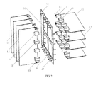
- a perpendicular and orthogonal interconnection system provided by this embodiment of the present invention includes a first board group, a second board group orthogonal to the first board group, and a center backplane 32 arranged between the first board group and the second board group, where the first board group includes a plurality of first boards 11 parallel to each other, and the second board group includes a plurality of second boards 12 parallel to each other; a plurality of curved male connectors 1 is arranged on each of the first boards 11, a plurality of curved female connectors 2 is arranged on each of the second boards 12, the curved male connectors 1 and the curved female connectors 2 directly cooperate and are connected in one-to-one correspondence, and the curved male connectors 1 and the curved female connectors 2 in one-to-one correspondence constitute orthogonal connectors.
- the perpendicular and orthogonal interconnection system When the perpendicular and orthogonal interconnection system is upgraded, only the first board group and the second board group need to be replaced, which is rather simple, shortens a signal link, and is low in upgrade costs.
- the perpendicular and orthogonal interconnection system does not need an orthogonal backplane and connectors (for example, orthogonal straight male connectors) on two sides of the orthogonal backplane, thereby greatly reducing costs. Because there is no orthogonal backplane, board signals are directly connected, and a link length reaches the minimum.
- cooling air can directly enter a rear side board from a front side board, air ducts are truly interconnected, and heat dissipation capability of the system is raised to the maximum, thereby solving the problem of air duct design difficulty caused by perpendicular front and rear air ducts of a system in an existing orthogonal architecture.
- the center backplane 32 has a hollow frame structure.
- the center backplane 32 is in the shape of a square or a rectangle, which is easy for processing and fabrication.
- a first connector 21 electrically connected to the curved male connectors 1 is arranged on each of the first boards 11
- a second connector 22 electrically connected to the curved female connectors 2 is arranged on each of the second boards 12
- third connectors 33 and fourth connectors 34 electrically connected to the first connectors 21 and the second connectors 22 are separately arranged on two perpendicular sides of the center backplane 32.
- a power source or a control signal is transmitted to the curved male connectors 1 sequentially through the third connectors 33, the first connectors 21, and the first boards 11, so as to supply power to the curved male connectors 1 and control the curved male connectors 1.
- a power source or a control signal is transmitted to the curved female connectors 2 sequentially through the fourth connectors 34, the second connectors 22, and the second boards 12, so as to supply power to the curved female connectors 2 and control the curved female connectors 2.
- a transmission path of the power source and the control signal is the shortest, and attenuation is the smallest, which is conducive to power supply and control.
- center backplane 32 enables the first connectors 21 to cooperate with and connect to the third connectors 33, and enables the second connectors 22 to cooperate with and connect to the fourth connectors 34; therefore, a current and a low-speed control signal are transmitted independently, and reliability of the perpendicular and orthogonal interconnection system is improved.
- the perpendicular and orthogonal interconnection system is arranged in a main cabinet with a plurality of guide rails, the guide rails may be arranged longitudinally or transversely, and the first boards 11 and the second boards 12 are orthogonal after being installed along the guide rails of the main cabinet; therefore, installation of the boards is more convenient.
- the main cabinet is relatively stable, and reliability of the system is improved.
- the center backplane 32 is set to have the hollow frame structure, which improves stability of installing the center backplane 32 to the main cabinet.
- the center backplane 32 is longitudinally arranged in the middle of the main cabinet.
- One side of the center backplane 32 is the first board group, and the other side of the center backplane 32 is the second board group.
- the boards in each board group are evenly and reasonably arranged, which is conducive to air duct design and further improves heat dissipation capability of the perpendicular and orthogonal interconnection system.
- a perpendicular and orthogonal interconnection system includes a first board group, a second board group orthogonal to the first board group, and a center backplane 37 arranged between the first board group and the second board group, where the first board group includes a plurality of first boards 11 parallel to each other, and the second board group includes a plurality of second boards 12 parallel to each other; a plurality of curved male connectors 1 is arranged on each of the first boards 11, a plurality of curved female connectors 2 is arranged on each of the second boards 12, the curved male connectors 1 and the curved female connectors 2 directly cooperate and are connected in one-to-one correspondence, and the curved male connectors 1 and the curved female connectors 2 in one-to-one correspondence constitute orthogonal connectors.
- the perpendicular and orthogonal interconnection system When the perpendicular and orthogonal interconnection system is upgraded, only the first board group and the second board group need to be replaced, which is rather simple and low in upgrade costs. Compared with the prior art, the perpendicular and orthogonal interconnection system does not need an orthogonal backplane and connectors (for example, orthogonal straight male connectors) on two sides of the orthogonal backplane, thereby greatly reducing costs. Because there is no orthogonal backplane, board signals are directly connected, and a link length reaches the minimum.
- orthogonal backplane and connectors for example, orthogonal straight male connectors
- cooling air can directly enter a rear side board from a front side board, air ducts are truly interconnected, and heat dissipation capability of the system is raised to the maximum, thereby solving the problem of air duct design difficulty caused by perpendicular front and rear air ducts of a system in an existing orthogonal architecture.
- the center backplane 37 is L-shaped, which is easy for processing and fabrication and saves materials.
- a first connector 21 electrically connected to the curved male connectors 1 is arranged on each of the first boards 11
- a second connector 22 electrically connected to the curved female connectors 2 is arranged on each of the second boards 12
- third connectors 33 and fourth connectors 34 electrically connected to the first connectors 21 and the second connectors 22 are separately arranged on sides of the center backplane 37.
- a power source or a control signal is transmitted to the curved male connectors 1 sequentially through the third connectors 33, the first connectors 21, and the first boards 11, so as to supply power to the curved male connectors 1 and control the curved male connectors 1.
- a power source or a control signal is transmitted to the curved female connectors 2 sequentially through the fourth connectors 34, the second connectors 22, and the second boards 12, so as to supply power to the curved female connectors 2 and control the curved female connectors 2.
- a transmission path of the power source and the control signal is the shortest, and attenuation is the smallest, which is conducive to power supply and control.
- the center backplane 37 enables the first connectors 21 to cooperate with and connect to the third connectors 33, and enables the second connectors 22 to cooperate with and connect to the fourth connectors 34; therefore, a current and a low-speed control signal are transmitted independently, and reliability of the perpendicular and orthogonal interconnection system is improved.
- the perpendicular and orthogonal interconnection system is arranged in a main cabinet with a plurality of longitudinal or transverse guide rails, and the first boards 11 and the second boards 12 are orthogonal after being installed along the guide rails of the main cabinet; therefore, installation of the boards is more convenient.
- the main cabinet is relatively stable, and reliability of the system is improved.
- the center backplane 37 is L-shaped, which ensures stability of installing the center backplane 37 to the main cabinet and saves materials.
- the center backplane 37 is longitudinally arranged in the middle of the main cabinet.
- One side of the center backplane 37 is the first board group, and the other side of the center backplane 37 is the second board group.
- the boards in each board group are evenly and reasonably arranged, which is conducive to air duct design and further improves heat dissipation capability of the perpendicular and orthogonal interconnection system.
- a perpendicular and orthogonal interconnection system provided by this embodiment of the present invention includes a first board group, a second board group orthogonal to the first board group, and a center backplane 38 arranged between the first board group and the second board group, where the first board group includes a plurality of first boards 11 parallel to each other, and the second board group includes a plurality of second boards 12 parallel to each other; a plurality of curved male connectors 1 is arranged on each of the first boards 11, a plurality of curved female connectors 2 is arranged on each of the second boards 12, the curved male connectors 1 and the curved female connectors 2 directly cooperate and are connected in one-to-one correspondence, and the curved male connectors 1 and the curved female connectors 2 in one-to-one correspondence constitute orthogonal connectors.
- the perpendicular and orthogonal interconnection system When the perpendicular and orthogonal interconnection system is upgraded, only the first board group and the second board group need to be replaced, which is rather simple, shortens a signal link, and is low in upgrade costs.
- the perpendicular and orthogonal interconnection system does not need an orthogonal backplane and connectors (for example, orthogonal straight male connectors) on two sides of the orthogonal backplane, thereby greatly reducing costs. Because there is no orthogonal backplane, board signals are directly connected, and a link length reaches the minimum.
- cooling air can directly enter a rear side board from a front side board, air ducts are truly interconnected, and heat dissipation capability of the system is raised to the maximum, thereby solving the problem of air duct design difficulty caused by perpendicular front and rear air ducts of a system in an existing orthogonal architecture.
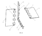
- the center backplane 38 may be divided into a plurality of independent backplanes, for example, a longitudinal backplane 35 and a transverse backplane 36. In this way, each independent backplane is easily shaped; besides, materials are saved, resulting in lower costs.
- a first connector 21 electrically connected to the curved male connectors 1 is arranged on each of the first boards 11
- a second connector 22 electrically connected to the curved female connectors 2 is arranged on each of the second boards 12
- third connectors 33 and fourth connectors 34 electrically connected to the first connectors 21 and the second connectors 22 are separately arranged on the longitudinal backplane 35 and the transverse backplane 36.
- a power source or a control signal is transmitted to the curved male connectors 1 sequentially through the third connectors 33, the first connectors 21, and the first boards 11, so as to supply power to the curved male connectors 1 and control the curved male connectors 1.
- a power source or a control signal is transmitted to the curved female connectors 2 sequentially through the fourth connectors 34, the second connectors 22, and the second boards 12, so as to supply power to the curved female connectors 2 and control the curved female connectors 2.
- a transmission path of the power source and the control signal is the shortest, and attenuation is the smallest, which is conducive to power supply and control.
- the longitudinal backplane 35 enables the first connectors 21 to cooperate with and connect to the third connectors 33
- the transverse backplane 36 enables the second connectors 22 to cooperate with and connect to the fourth connectors 34; therefore, a current and a low-speed control signal is transmitted independently, and reliability of the perpendicular and orthogonal interconnection system is improved.
- the perpendicular and orthogonal interconnection system is arranged in a main cabinet with a plurality of longitudinal or transverse guide rails, and the first boards 11 and the second boards 12 are orthogonal after being installed along the guide rails of the main cabinet; therefore, installation of the boards is more convenient.
- the main cabinet is relatively stable, and reliability of the system is improved.
- the center backplane 38 is divided into the longitudinal backplane 35 and the transverse backplane 36, which ensures stability of installing the center backplane 38 to the main cabinet and saves materials.
- the center backplane 38 is longitudinally arranged in the middle of the main cabinet.
- One side of the center backplane 38 is the first board group, and the other side of the center backplane 38 is the second board group.
- the boards in each board group are evenly and reasonably arranged, which is conducive to air duct design and further improves heat dissipation capability of the perpendicular and orthogonal interconnection system.
- the perpendicular and orthogonal interconnection system is applicable to various communications devices; therefore, its upgrade is convenient, signal quality is improved, heat dissipation is ideal, and material costs are saved.
Landscapes
- Engineering & Computer Science (AREA)
- Microelectronics & Electronic Packaging (AREA)
- Manufacturing & Machinery (AREA)
- Computer Networks & Wireless Communication (AREA)
- Mounting Of Printed Circuit Boards And The Like (AREA)
- Cooling Or The Like Of Electrical Apparatus (AREA)
- Coupling Device And Connection With Printed Circuit (AREA)
Priority Applications (1)
| Application Number | Priority Date | Filing Date | Title |
|---|---|---|---|
| EP16186572.0A EP3190665A1 (de) | 2012-05-04 | 2012-10-26 | System zur senkrechten und orthogonalen verbindung und kommunikationsvorrichtung |
Applications Claiming Priority (2)
| Application Number | Priority Date | Filing Date | Title |
|---|---|---|---|
| CN201210136706.1A CN102695393B (zh) | 2012-05-04 | 2012-05-04 | 一种垂直正交互连系统及通信设备 |
| PCT/CN2012/083542 WO2013163867A1 (zh) | 2012-05-04 | 2012-10-26 | 一种垂直正交互连系统及通信设备 |
Related Child Applications (2)
| Application Number | Title | Priority Date | Filing Date |
|---|---|---|---|
| EP16186572.0A Division-Into EP3190665A1 (de) | 2012-05-04 | 2012-10-26 | System zur senkrechten und orthogonalen verbindung und kommunikationsvorrichtung |
| EP16186572.0A Division EP3190665A1 (de) | 2012-05-04 | 2012-10-26 | System zur senkrechten und orthogonalen verbindung und kommunikationsvorrichtung |
Publications (3)
| Publication Number | Publication Date |
|---|---|
| EP2836058A1 true EP2836058A1 (de) | 2015-02-11 |
| EP2836058A4 EP2836058A4 (de) | 2015-03-11 |
| EP2836058B1 EP2836058B1 (de) | 2016-12-07 |
Family
ID=46860621
Family Applications (2)
| Application Number | Title | Priority Date | Filing Date |
|---|---|---|---|
| EP16186572.0A Withdrawn EP3190665A1 (de) | 2012-05-04 | 2012-10-26 | System zur senkrechten und orthogonalen verbindung und kommunikationsvorrichtung |
| EP12876061.8A Active EP2836058B1 (de) | 2012-05-04 | 2012-10-26 | Vertikales orthogonales verbindungssystem und kommunikationsvorrichtung |
Family Applications Before (1)
| Application Number | Title | Priority Date | Filing Date |
|---|---|---|---|
| EP16186572.0A Withdrawn EP3190665A1 (de) | 2012-05-04 | 2012-10-26 | System zur senkrechten und orthogonalen verbindung und kommunikationsvorrichtung |
Country Status (4)
| Country | Link |
|---|---|
| US (2) | US9532471B2 (de) |
| EP (2) | EP3190665A1 (de) |
| CN (1) | CN102695393B (de) |
| WO (1) | WO2013163867A1 (de) |
Families Citing this family (32)
| Publication number | Priority date | Publication date | Assignee | Title |
|---|---|---|---|---|
| CN102695393B (zh) | 2012-05-04 | 2014-11-05 | 华为技术有限公司 | 一种垂直正交互连系统及通信设备 |
| CN103780516B (zh) * | 2012-10-19 | 2017-06-09 | 华为技术有限公司 | 一种立体背板 |
| CN103813677A (zh) * | 2012-11-05 | 2014-05-21 | 华为技术有限公司 | 背板、机柜级通讯设备以及更换背板的方法 |
| CN103050800B (zh) * | 2012-12-25 | 2015-04-08 | 华为技术有限公司 | 电气连接装置及电子设备 |
| CN103906404B (zh) * | 2012-12-26 | 2016-08-24 | 华为机器有限公司 | 利于散热的集成多模块的设备 |
| CN103974538B (zh) * | 2013-02-05 | 2017-09-12 | 华为技术有限公司 | 电子设备、电子系统及其电路板互联架构 |
| CN104254199B (zh) * | 2013-06-27 | 2018-07-31 | 华为技术有限公司 | 电子板卡系统及电子设备 |
| US9840185B2 (en) | 2013-07-30 | 2017-12-12 | Uusi, Llc | Vehicle accessory control arrangement |
| CN104064893B (zh) | 2014-06-06 | 2016-06-29 | 华为技术有限公司 | 一种背板及通讯设备 |
| CN105813414A (zh) * | 2014-12-30 | 2016-07-27 | 中兴通讯股份有限公司 | 一种背板、双面插背板以及交叉板 |
| CN106953816A (zh) * | 2016-01-06 | 2017-07-14 | 中兴通讯股份有限公司 | 通讯交换设备 |
| CN107154856A (zh) * | 2016-03-03 | 2017-09-12 | 中兴通讯股份有限公司 | 具有平行背板的通讯设备及其平行背板的布置方法 |
| US10512187B2 (en) | 2017-09-05 | 2019-12-17 | Quanta Computer Inc. | Alignment device for orthogonal engagement of line cards and fabric cards in a server |
| CN108235637B (zh) * | 2017-12-15 | 2020-08-21 | 深圳市恒扬数据股份有限公司 | 一种用于通信设备的垂直正交系统及通信设备 |
| CN108270097A (zh) * | 2017-12-29 | 2018-07-10 | 曙光信息产业(北京)有限公司 | 一种正交高速背板 |
| CN110401077B (zh) * | 2018-06-29 | 2021-07-30 | 中航光电科技股份有限公司 | 一种数据互联传输机箱 |
| US10568238B1 (en) * | 2018-08-10 | 2020-02-18 | Facebook, Inc. | Modular network switch |
| CN109347767A (zh) * | 2018-09-13 | 2019-02-15 | 恒为科技(上海)股份有限公司 | 一种基于正交连接方式的电信计算硬件构架 |
| CN110727631B (zh) * | 2019-09-12 | 2023-08-08 | 无锡江南计算技术研究所 | 一种基于双中板正交与非正交异构互连的h型组装方法 |
| CN111341359B (zh) * | 2020-02-23 | 2021-08-06 | 苏州浪潮智能科技有限公司 | 一种服务器高密度硬盘背板分板装置 |
| CN113821383A (zh) * | 2020-06-19 | 2021-12-21 | 华为技术有限公司 | 一种存储系统 |
| CN114126311B (zh) * | 2020-08-31 | 2025-08-22 | 中兴通讯股份有限公司 | 线缆连接结构、单板组件、单板组件连接结构 |
| CN112291640B (zh) * | 2020-10-30 | 2022-02-22 | 迈普通信技术股份有限公司 | 一种正交机架设备及通信设备 |
| CN112751787B (zh) * | 2020-12-30 | 2022-04-26 | 杭州迪普科技股份有限公司 | 机框式设备、板卡间报文转发方法 |
| CN113113822A (zh) * | 2021-04-25 | 2021-07-13 | 无锡江南计算技术研究所 | 一种正交与非正交背板混合互连方法、连接器 |
| CN115603078A (zh) * | 2021-07-08 | 2023-01-13 | 中兴智能科技南京有限公司(Cn) | 电连接器组件及通讯设备 |
| CN115864032A (zh) * | 2021-09-24 | 2023-03-28 | 华为技术有限公司 | 正交系统架构及网络设备 |
| CN116133313B (zh) * | 2021-11-12 | 2025-06-13 | 华为技术有限公司 | 通信设备和业务信号调度的方法 |
| CN116192243A (zh) * | 2021-11-26 | 2023-05-30 | 华为技术有限公司 | 一种光背板互连装置及通信设备 |
| CN118509732A (zh) * | 2023-02-07 | 2024-08-16 | 中兴通讯股份有限公司 | 垂直正交互连系统及通信设备 |
| US12568597B2 (en) * | 2023-08-24 | 2026-03-03 | Western Digital Technologies, Inc. | Staged high-density backplane for electronic modules |
| US20250120034A1 (en) * | 2023-10-05 | 2025-04-10 | Tesla, Inc. | Connector assembly with pullback |
Family Cites Families (21)
| Publication number | Priority date | Publication date | Assignee | Title |
|---|---|---|---|---|
| US5199881A (en) * | 1991-12-03 | 1993-04-06 | Hughes Aircraft Company | Hermaphroditic interconnection of circuit boards |
| CN2264983Y (zh) | 1996-05-22 | 1997-10-15 | 深圳市华为技术有限公司 | 插件板的连接结构 |
| US5971785A (en) * | 1997-08-22 | 1999-10-26 | Molex Incorporated | Hermaphroditic connector for printed circuit boards |
| JP3347662B2 (ja) * | 1998-02-04 | 2002-11-20 | ヒロセ電機株式会社 | 電気コネクタ |
| JP3698233B2 (ja) * | 1998-04-28 | 2005-09-21 | 富士通株式会社 | プリント配線板実装構造 |
| US6462957B1 (en) * | 1999-11-18 | 2002-10-08 | Nortel Networks Limited | High performance orthogonal interconnect architecture without midplane |
| US6528737B1 (en) * | 2000-08-16 | 2003-03-04 | Nortel Networks Limited | Midplane configuration featuring surface contact connectors |
| US6608762B2 (en) * | 2001-06-01 | 2003-08-19 | Hyperchip Inc. | Midplane for data processing apparatus |
| US7050307B2 (en) | 2002-06-28 | 2006-05-23 | Sun Microsystems, Inc. | Circuit board orientation in a computer system |
| US7043655B2 (en) * | 2002-11-06 | 2006-05-09 | Sun Microsystems, Inc. | Redundant clock synthesizer |
| US6866518B1 (en) * | 2003-09-23 | 2005-03-15 | Hon Hai Precision Ind. Co., Ltd. | Electrical interconnection between multiple printed circuit boards |
| US7108556B2 (en) * | 2004-07-01 | 2006-09-19 | Amphenol Corporation | Midplane especially applicable to an orthogonal architecture electronic system |
| US7331717B2 (en) | 2004-07-01 | 2008-02-19 | Amphenol Corporation | Flexible optical interconnection system |
| US7088583B2 (en) * | 2004-10-25 | 2006-08-08 | International Business Machines Corporation | System for airflow management in electronic enclosures |
| US20060228912A1 (en) * | 2005-04-07 | 2006-10-12 | Fci Americas Technology, Inc. | Orthogonal backplane connector |
| CN2819710Y (zh) | 2005-08-31 | 2006-09-20 | 华为技术有限公司 | 一种机箱 |
| US7354274B2 (en) * | 2006-02-07 | 2008-04-08 | Fci Americas Technology, Inc. | Connector assembly for interconnecting printed circuit boards |
| WO2009108092A1 (en) * | 2008-02-27 | 2009-09-03 | Telefonaktiebolaget L M Ericsson (Publ) | System card architecture for switching device |
| US7988456B2 (en) | 2009-01-14 | 2011-08-02 | Tyco Electronics Corporation | Orthogonal connector system |
| CN101882955B (zh) * | 2010-04-26 | 2013-04-17 | 华为技术有限公司 | 光背板互连系统及通信设备 |
| CN102695393B (zh) * | 2012-05-04 | 2014-11-05 | 华为技术有限公司 | 一种垂直正交互连系统及通信设备 |
-
2012
- 2012-05-04 CN CN201210136706.1A patent/CN102695393B/zh active Active
- 2012-10-26 EP EP16186572.0A patent/EP3190665A1/de not_active Withdrawn
- 2012-10-26 EP EP12876061.8A patent/EP2836058B1/de active Active
- 2012-10-26 WO PCT/CN2012/083542 patent/WO2013163867A1/zh not_active Ceased
-
2014
- 2014-11-03 US US14/531,521 patent/US9532471B2/en active Active
-
2016
- 2016-12-08 US US15/373,133 patent/US10084255B2/en active Active
Also Published As
| Publication number | Publication date |
|---|---|
| EP2836058A4 (de) | 2015-03-11 |
| CN102695393A (zh) | 2012-09-26 |
| EP2836058B1 (de) | 2016-12-07 |
| US20150049451A1 (en) | 2015-02-19 |
| US10084255B2 (en) | 2018-09-25 |
| US9532471B2 (en) | 2016-12-27 |
| CN102695393B (zh) | 2014-11-05 |
| WO2013163867A1 (zh) | 2013-11-07 |
| EP3190665A1 (de) | 2017-07-12 |
| US20170093065A1 (en) | 2017-03-30 |
Similar Documents
| Publication | Publication Date | Title |
|---|---|---|
| US9532471B2 (en) | Perpendicular and orthogonal interconnection system and communications device | |
| CN101984599B (zh) | 背板及通讯设备、通讯系统 | |
| US9059551B2 (en) | Backplane apparatus and communication device | |
| EP2830257B1 (de) | Atca-rückwandplatine | |
| CN103718658A (zh) | 背板、插框和网络设备 | |
| CN107317770A (zh) | 背板装置、通信设备 | |
| BR112016028302B1 (pt) | Painel posterior e dispositivo de comunicações | |
| CN105376659B (zh) | 一种光背板组件及一种通信设备 | |
| CN109757052A (zh) | 一种通信设备数据信号传输装置及通信设备 | |
| CN107396593B (zh) | 机柜系统 | |
| WO2007117944A1 (en) | Backplane interconnection system and method | |
| CN104820473A (zh) | 一种机架服务器基板及机架服务器基板组 | |
| CN108427162B (zh) | 光背板互连系统 | |
| CN105027518B (zh) | 用于通信设备的互连系统 | |
| CN105471752B (zh) | 基于交换网实现机架堆叠的设备、方法和系统 | |
| WO2017118386A1 (zh) | 通讯交换设备 | |
| CN110990326B (zh) | 一种用于ATCA架构的高速PCI Express转接驱动单元 | |
| EP2897325B1 (de) | Kommunikationssystem | |
| CN211457756U (zh) | 一种超短波开关矩阵 | |
| CN223712162U (zh) | 数据采集站及用于数据采集站的扩展坞 | |
| CN107370681A (zh) | 一种模块化路由器 | |
| US20230262920A1 (en) | Floating extended panel solution for dci chassis | |
| CN220342419U (zh) | 一种无源光纤交叉设备及光交叉互联系统 | |
| CN108768897B (zh) | 端口扩展设备和堆叠系统 | |
| CN117880657A (zh) | 交换网板组件、通信设备和交换网板组件的制作方法 |
Legal Events
| Date | Code | Title | Description |
|---|---|---|---|
| PUAI | Public reference made under article 153(3) epc to a published international application that has entered the european phase |
Free format text: ORIGINAL CODE: 0009012 |
|
| 17P | Request for examination filed |
Effective date: 20141105 |
|
| AK | Designated contracting states |
Kind code of ref document: A1 Designated state(s): AL AT BE BG CH CY CZ DE DK EE ES FI FR GB GR HR HU IE IS IT LI LT LU LV MC MK MT NL NO PL PT RO RS SE SI SK SM TR |
|
| AX | Request for extension of the european patent |
Extension state: BA ME |
|
| A4 | Supplementary search report drawn up and despatched |
Effective date: 20150206 |
|
| RIC1 | Information provided on ipc code assigned before grant |
Ipc: H05K 7/02 20060101AFI20150202BHEP Ipc: H04Q 1/02 20060101ALI20150202BHEP Ipc: H01R 12/00 20060101ALI20150202BHEP |
|
| DAX | Request for extension of the european patent (deleted) | ||
| RIC1 | Information provided on ipc code assigned before grant |
Ipc: H05K 7/02 20060101AFI20160504BHEP Ipc: H01R 12/00 20060101ALI20160504BHEP Ipc: H04Q 1/02 20060101ALI20160504BHEP |
|
| GRAP | Despatch of communication of intention to grant a patent |
Free format text: ORIGINAL CODE: EPIDOSNIGR1 |
|
| INTG | Intention to grant announced |
Effective date: 20160613 |
|
| GRAS | Grant fee paid |
Free format text: ORIGINAL CODE: EPIDOSNIGR3 |
|
| GRAA | (expected) grant |
Free format text: ORIGINAL CODE: 0009210 |
|
| AK | Designated contracting states |
Kind code of ref document: B1 Designated state(s): AL AT BE BG CH CY CZ DE DK EE ES FI FR GB GR HR HU IE IS IT LI LT LU LV MC MK MT NL NO PL PT RO RS SE SI SK SM TR |
|
| REG | Reference to a national code |
Ref country code: GB Ref legal event code: FG4D |
|
| REG | Reference to a national code |
Ref country code: CH Ref legal event code: EP Ref country code: AT Ref legal event code: REF Ref document number: 852704 Country of ref document: AT Kind code of ref document: T Effective date: 20161215 |
|
| REG | Reference to a national code |
Ref country code: IE Ref legal event code: FG4D |
|
| REG | Reference to a national code |
Ref country code: DE Ref legal event code: R096 Ref document number: 602012026472 Country of ref document: DE |
|
| PG25 | Lapsed in a contracting state [announced via postgrant information from national office to epo] |
Ref country code: LV Free format text: LAPSE BECAUSE OF FAILURE TO SUBMIT A TRANSLATION OF THE DESCRIPTION OR TO PAY THE FEE WITHIN THE PRESCRIBED TIME-LIMIT Effective date: 20161207 |
|
| REG | Reference to a national code |
Ref country code: NL Ref legal event code: FP |
|
| REG | Reference to a national code |
Ref country code: SE Ref legal event code: TRGR |
|
| REG | Reference to a national code |
Ref country code: LT Ref legal event code: MG4D |
|
| PG25 | Lapsed in a contracting state [announced via postgrant information from national office to epo] |
Ref country code: LT Free format text: LAPSE BECAUSE OF FAILURE TO SUBMIT A TRANSLATION OF THE DESCRIPTION OR TO PAY THE FEE WITHIN THE PRESCRIBED TIME-LIMIT Effective date: 20161207 Ref country code: NO Free format text: LAPSE BECAUSE OF FAILURE TO SUBMIT A TRANSLATION OF THE DESCRIPTION OR TO PAY THE FEE WITHIN THE PRESCRIBED TIME-LIMIT Effective date: 20170307 Ref country code: GR Free format text: LAPSE BECAUSE OF FAILURE TO SUBMIT A TRANSLATION OF THE DESCRIPTION OR TO PAY THE FEE WITHIN THE PRESCRIBED TIME-LIMIT Effective date: 20170308 |
|
| REG | Reference to a national code |
Ref country code: AT Ref legal event code: MK05 Ref document number: 852704 Country of ref document: AT Kind code of ref document: T Effective date: 20161207 |
|
| PG25 | Lapsed in a contracting state [announced via postgrant information from national office to epo] |
Ref country code: ES Free format text: LAPSE BECAUSE OF FAILURE TO SUBMIT A TRANSLATION OF THE DESCRIPTION OR TO PAY THE FEE WITHIN THE PRESCRIBED TIME-LIMIT Effective date: 20161207 Ref country code: FI Free format text: LAPSE BECAUSE OF FAILURE TO SUBMIT A TRANSLATION OF THE DESCRIPTION OR TO PAY THE FEE WITHIN THE PRESCRIBED TIME-LIMIT Effective date: 20161207 Ref country code: HR Free format text: LAPSE BECAUSE OF FAILURE TO SUBMIT A TRANSLATION OF THE DESCRIPTION OR TO PAY THE FEE WITHIN THE PRESCRIBED TIME-LIMIT Effective date: 20161207 Ref country code: RS Free format text: LAPSE BECAUSE OF FAILURE TO SUBMIT A TRANSLATION OF THE DESCRIPTION OR TO PAY THE FEE WITHIN THE PRESCRIBED TIME-LIMIT Effective date: 20161207 |
|
| PG25 | Lapsed in a contracting state [announced via postgrant information from national office to epo] |
Ref country code: CZ Free format text: LAPSE BECAUSE OF FAILURE TO SUBMIT A TRANSLATION OF THE DESCRIPTION OR TO PAY THE FEE WITHIN THE PRESCRIBED TIME-LIMIT Effective date: 20161207 Ref country code: EE Free format text: LAPSE BECAUSE OF FAILURE TO SUBMIT A TRANSLATION OF THE DESCRIPTION OR TO PAY THE FEE WITHIN THE PRESCRIBED TIME-LIMIT Effective date: 20161207 Ref country code: IS Free format text: LAPSE BECAUSE OF FAILURE TO SUBMIT A TRANSLATION OF THE DESCRIPTION OR TO PAY THE FEE WITHIN THE PRESCRIBED TIME-LIMIT Effective date: 20170407 Ref country code: RO Free format text: LAPSE BECAUSE OF FAILURE TO SUBMIT A TRANSLATION OF THE DESCRIPTION OR TO PAY THE FEE WITHIN THE PRESCRIBED TIME-LIMIT Effective date: 20161207 Ref country code: SK Free format text: LAPSE BECAUSE OF FAILURE TO SUBMIT A TRANSLATION OF THE DESCRIPTION OR TO PAY THE FEE WITHIN THE PRESCRIBED TIME-LIMIT Effective date: 20161207 |
|
| PG25 | Lapsed in a contracting state [announced via postgrant information from national office to epo] |
Ref country code: SM Free format text: LAPSE BECAUSE OF FAILURE TO SUBMIT A TRANSLATION OF THE DESCRIPTION OR TO PAY THE FEE WITHIN THE PRESCRIBED TIME-LIMIT Effective date: 20161207 Ref country code: BE Free format text: LAPSE BECAUSE OF FAILURE TO SUBMIT A TRANSLATION OF THE DESCRIPTION OR TO PAY THE FEE WITHIN THE PRESCRIBED TIME-LIMIT Effective date: 20161207 Ref country code: PL Free format text: LAPSE BECAUSE OF FAILURE TO SUBMIT A TRANSLATION OF THE DESCRIPTION OR TO PAY THE FEE WITHIN THE PRESCRIBED TIME-LIMIT Effective date: 20161207 Ref country code: AT Free format text: LAPSE BECAUSE OF FAILURE TO SUBMIT A TRANSLATION OF THE DESCRIPTION OR TO PAY THE FEE WITHIN THE PRESCRIBED TIME-LIMIT Effective date: 20161207 Ref country code: IT Free format text: LAPSE BECAUSE OF FAILURE TO SUBMIT A TRANSLATION OF THE DESCRIPTION OR TO PAY THE FEE WITHIN THE PRESCRIBED TIME-LIMIT Effective date: 20161207 Ref country code: BG Free format text: LAPSE BECAUSE OF FAILURE TO SUBMIT A TRANSLATION OF THE DESCRIPTION OR TO PAY THE FEE WITHIN THE PRESCRIBED TIME-LIMIT Effective date: 20170307 Ref country code: PT Free format text: LAPSE BECAUSE OF FAILURE TO SUBMIT A TRANSLATION OF THE DESCRIPTION OR TO PAY THE FEE WITHIN THE PRESCRIBED TIME-LIMIT Effective date: 20170407 |
|
| REG | Reference to a national code |
Ref country code: DE Ref legal event code: R097 Ref document number: 602012026472 Country of ref document: DE |
|
| REG | Reference to a national code |
Ref country code: FR Ref legal event code: PLFP Year of fee payment: 6 |
|
| PLBE | No opposition filed within time limit |
Free format text: ORIGINAL CODE: 0009261 |
|
| STAA | Information on the status of an ep patent application or granted ep patent |
Free format text: STATUS: NO OPPOSITION FILED WITHIN TIME LIMIT |
|
| 26N | No opposition filed |
Effective date: 20170908 |
|
| PG25 | Lapsed in a contracting state [announced via postgrant information from national office to epo] |
Ref country code: DK Free format text: LAPSE BECAUSE OF FAILURE TO SUBMIT A TRANSLATION OF THE DESCRIPTION OR TO PAY THE FEE WITHIN THE PRESCRIBED TIME-LIMIT Effective date: 20161207 Ref country code: SI Free format text: LAPSE BECAUSE OF FAILURE TO SUBMIT A TRANSLATION OF THE DESCRIPTION OR TO PAY THE FEE WITHIN THE PRESCRIBED TIME-LIMIT Effective date: 20161207 |
|
| PG25 | Lapsed in a contracting state [announced via postgrant information from national office to epo] |
Ref country code: MC Free format text: LAPSE BECAUSE OF FAILURE TO SUBMIT A TRANSLATION OF THE DESCRIPTION OR TO PAY THE FEE WITHIN THE PRESCRIBED TIME-LIMIT Effective date: 20161207 |
|
| REG | Reference to a national code |
Ref country code: CH Ref legal event code: PL |
|
| REG | Reference to a national code |
Ref country code: IE Ref legal event code: MM4A |
|
| PG25 | Lapsed in a contracting state [announced via postgrant information from national office to epo] |
Ref country code: LU Free format text: LAPSE BECAUSE OF NON-PAYMENT OF DUE FEES Effective date: 20171026 Ref country code: LI Free format text: LAPSE BECAUSE OF NON-PAYMENT OF DUE FEES Effective date: 20171031 Ref country code: CH Free format text: LAPSE BECAUSE OF NON-PAYMENT OF DUE FEES Effective date: 20171031 |
|
| REG | Reference to a national code |
Ref country code: FR Ref legal event code: PLFP Year of fee payment: 7 |
|
| PG25 | Lapsed in a contracting state [announced via postgrant information from national office to epo] |
Ref country code: MT Free format text: LAPSE BECAUSE OF NON-PAYMENT OF DUE FEES Effective date: 20171026 |
|
| PG25 | Lapsed in a contracting state [announced via postgrant information from national office to epo] |
Ref country code: IE Free format text: LAPSE BECAUSE OF NON-PAYMENT OF DUE FEES Effective date: 20171026 |
|
| PG25 | Lapsed in a contracting state [announced via postgrant information from national office to epo] |
Ref country code: HU Free format text: LAPSE BECAUSE OF FAILURE TO SUBMIT A TRANSLATION OF THE DESCRIPTION OR TO PAY THE FEE WITHIN THE PRESCRIBED TIME-LIMIT; INVALID AB INITIO Effective date: 20121026 |
|
| PG25 | Lapsed in a contracting state [announced via postgrant information from national office to epo] |
Ref country code: CY Free format text: LAPSE BECAUSE OF FAILURE TO SUBMIT A TRANSLATION OF THE DESCRIPTION OR TO PAY THE FEE WITHIN THE PRESCRIBED TIME-LIMIT Effective date: 20161207 |
|
| PG25 | Lapsed in a contracting state [announced via postgrant information from national office to epo] |
Ref country code: MK Free format text: LAPSE BECAUSE OF FAILURE TO SUBMIT A TRANSLATION OF THE DESCRIPTION OR TO PAY THE FEE WITHIN THE PRESCRIBED TIME-LIMIT Effective date: 20161207 |
|
| PG25 | Lapsed in a contracting state [announced via postgrant information from national office to epo] |
Ref country code: TR Free format text: LAPSE BECAUSE OF FAILURE TO SUBMIT A TRANSLATION OF THE DESCRIPTION OR TO PAY THE FEE WITHIN THE PRESCRIBED TIME-LIMIT Effective date: 20161207 |
|
| PG25 | Lapsed in a contracting state [announced via postgrant information from national office to epo] |
Ref country code: AL Free format text: LAPSE BECAUSE OF FAILURE TO SUBMIT A TRANSLATION OF THE DESCRIPTION OR TO PAY THE FEE WITHIN THE PRESCRIBED TIME-LIMIT Effective date: 20161207 |
|
| P01 | Opt-out of the competence of the unified patent court (upc) registered |
Effective date: 20230524 |
|
| PGFP | Annual fee paid to national office [announced via postgrant information from national office to epo] |
Ref country code: NL Payment date: 20250912 Year of fee payment: 14 |
|
| PGFP | Annual fee paid to national office [announced via postgrant information from national office to epo] |
Ref country code: GB Payment date: 20250904 Year of fee payment: 14 |
|
| PGFP | Annual fee paid to national office [announced via postgrant information from national office to epo] |
Ref country code: FR Payment date: 20250908 Year of fee payment: 14 |
|
| PGFP | Annual fee paid to national office [announced via postgrant information from national office to epo] |
Ref country code: SE Payment date: 20250910 Year of fee payment: 14 |
|
| PGFP | Annual fee paid to national office [announced via postgrant information from national office to epo] |
Ref country code: DE Payment date: 20250902 Year of fee payment: 14 |