EP2835545A2 - Käfig mit Ölumlaufschmierungseinrichtungen - Google Patents
Käfig mit Ölumlaufschmierungseinrichtungen Download PDFInfo
- Publication number
- EP2835545A2 EP2835545A2 EP20140176997 EP14176997A EP2835545A2 EP 2835545 A2 EP2835545 A2 EP 2835545A2 EP 20140176997 EP20140176997 EP 20140176997 EP 14176997 A EP14176997 A EP 14176997A EP 2835545 A2 EP2835545 A2 EP 2835545A2
- Authority
- EP
- European Patent Office
- Prior art keywords
- bore
- bearing
- cage
- bearing cage
- rolling element
- Prior art date
- Legal status (The legal status is an assumption and is not a legal conclusion. Google has not performed a legal analysis and makes no representation as to the accuracy of the status listed.)
- Granted
Links
Images




Classifications
-
- F—MECHANICAL ENGINEERING; LIGHTING; HEATING; WEAPONS; BLASTING
- F16—ENGINEERING ELEMENTS AND UNITS; GENERAL MEASURES FOR PRODUCING AND MAINTAINING EFFECTIVE FUNCTIONING OF MACHINES OR INSTALLATIONS; THERMAL INSULATION IN GENERAL
- F16C—SHAFTS; FLEXIBLE SHAFTS; ELEMENTS OR CRANKSHAFT MECHANISMS; ROTARY BODIES OTHER THAN GEARING ELEMENTS; BEARINGS
- F16C33/00—Parts of bearings; Special methods for making bearings or parts thereof
- F16C33/30—Parts of ball or roller bearings
- F16C33/66—Special parts or details in view of lubrication
- F16C33/6637—Special parts or details in view of lubrication with liquid lubricant
- F16C33/664—Retaining the liquid in or near the bearing
-
- F—MECHANICAL ENGINEERING; LIGHTING; HEATING; WEAPONS; BLASTING
- F01—MACHINES OR ENGINES IN GENERAL; ENGINE PLANTS IN GENERAL; STEAM ENGINES
- F01D—NON-POSITIVE DISPLACEMENT MACHINES OR ENGINES, e.g. STEAM TURBINES
- F01D25/00—Component parts, details, or accessories, not provided for in, or of interest apart from, other groups
- F01D25/16—Arrangement of bearings; Supporting or mounting bearings in casings
-
- F—MECHANICAL ENGINEERING; LIGHTING; HEATING; WEAPONS; BLASTING
- F01—MACHINES OR ENGINES IN GENERAL; ENGINE PLANTS IN GENERAL; STEAM ENGINES
- F01D—NON-POSITIVE DISPLACEMENT MACHINES OR ENGINES, e.g. STEAM TURBINES
- F01D25/00—Component parts, details, or accessories, not provided for in, or of interest apart from, other groups
- F01D25/18—Lubricating arrangements
-
- F—MECHANICAL ENGINEERING; LIGHTING; HEATING; WEAPONS; BLASTING
- F02—COMBUSTION ENGINES; HOT-GAS OR COMBUSTION-PRODUCT ENGINE PLANTS
- F02C—GAS-TURBINE PLANTS; AIR INTAKES FOR JET-PROPULSION PLANTS; CONTROLLING FUEL SUPPLY IN AIR-BREATHING JET-PROPULSION PLANTS
- F02C7/00—Features, components parts, details or accessories, not provided for in, or of interest apart form groups F02C1/00 - F02C6/00; Air intakes for jet-propulsion plants
- F02C7/06—Arrangements of bearings; Lubricating
-
- F—MECHANICAL ENGINEERING; LIGHTING; HEATING; WEAPONS; BLASTING
- F16—ENGINEERING ELEMENTS AND UNITS; GENERAL MEASURES FOR PRODUCING AND MAINTAINING EFFECTIVE FUNCTIONING OF MACHINES OR INSTALLATIONS; THERMAL INSULATION IN GENERAL
- F16C—SHAFTS; FLEXIBLE SHAFTS; ELEMENTS OR CRANKSHAFT MECHANISMS; ROTARY BODIES OTHER THAN GEARING ELEMENTS; BEARINGS
- F16C33/00—Parts of bearings; Special methods for making bearings or parts thereof
- F16C33/30—Parts of ball or roller bearings
- F16C33/38—Ball cages
- F16C33/3837—Massive or moulded cages having cage pockets surrounding the balls, e.g. machined window cages
- F16C33/3843—Massive or moulded cages having cage pockets surrounding the balls, e.g. machined window cages formed as one-piece cages, i.e. monoblock cages
- F16C33/385—Massive or moulded cages having cage pockets surrounding the balls, e.g. machined window cages formed as one-piece cages, i.e. monoblock cages made from metal, e.g. cast or machined window cages
-
- F—MECHANICAL ENGINEERING; LIGHTING; HEATING; WEAPONS; BLASTING
- F16—ENGINEERING ELEMENTS AND UNITS; GENERAL MEASURES FOR PRODUCING AND MAINTAINING EFFECTIVE FUNCTIONING OF MACHINES OR INSTALLATIONS; THERMAL INSULATION IN GENERAL
- F16C—SHAFTS; FLEXIBLE SHAFTS; ELEMENTS OR CRANKSHAFT MECHANISMS; ROTARY BODIES OTHER THAN GEARING ELEMENTS; BEARINGS
- F16C33/00—Parts of bearings; Special methods for making bearings or parts thereof
- F16C33/30—Parts of ball or roller bearings
- F16C33/46—Cages for rollers or needles
- F16C33/4605—Details of interaction of cage and race, e.g. retention or centring
-
- F—MECHANICAL ENGINEERING; LIGHTING; HEATING; WEAPONS; BLASTING
- F16—ENGINEERING ELEMENTS AND UNITS; GENERAL MEASURES FOR PRODUCING AND MAINTAINING EFFECTIVE FUNCTIONING OF MACHINES OR INSTALLATIONS; THERMAL INSULATION IN GENERAL
- F16C—SHAFTS; FLEXIBLE SHAFTS; ELEMENTS OR CRANKSHAFT MECHANISMS; ROTARY BODIES OTHER THAN GEARING ELEMENTS; BEARINGS
- F16C33/00—Parts of bearings; Special methods for making bearings or parts thereof
- F16C33/30—Parts of ball or roller bearings
- F16C33/46—Cages for rollers or needles
- F16C33/467—Details of individual pockets, e.g. shape or roller retaining means
-
- F—MECHANICAL ENGINEERING; LIGHTING; HEATING; WEAPONS; BLASTING
- F16—ENGINEERING ELEMENTS AND UNITS; GENERAL MEASURES FOR PRODUCING AND MAINTAINING EFFECTIVE FUNCTIONING OF MACHINES OR INSTALLATIONS; THERMAL INSULATION IN GENERAL
- F16C—SHAFTS; FLEXIBLE SHAFTS; ELEMENTS OR CRANKSHAFT MECHANISMS; ROTARY BODIES OTHER THAN GEARING ELEMENTS; BEARINGS
- F16C33/00—Parts of bearings; Special methods for making bearings or parts thereof
- F16C33/30—Parts of ball or roller bearings
- F16C33/46—Cages for rollers or needles
- F16C33/467—Details of individual pockets, e.g. shape or roller retaining means
- F16C33/4676—Details of individual pockets, e.g. shape or roller retaining means of the stays separating adjacent cage pockets, e.g. guide means for the bearing-surface of the rollers
-
- F—MECHANICAL ENGINEERING; LIGHTING; HEATING; WEAPONS; BLASTING
- F16—ENGINEERING ELEMENTS AND UNITS; GENERAL MEASURES FOR PRODUCING AND MAINTAINING EFFECTIVE FUNCTIONING OF MACHINES OR INSTALLATIONS; THERMAL INSULATION IN GENERAL
- F16C—SHAFTS; FLEXIBLE SHAFTS; ELEMENTS OR CRANKSHAFT MECHANISMS; ROTARY BODIES OTHER THAN GEARING ELEMENTS; BEARINGS
- F16C33/00—Parts of bearings; Special methods for making bearings or parts thereof
- F16C33/30—Parts of ball or roller bearings
- F16C33/58—Raceways; Race rings
- F16C33/583—Details of specific parts of races
-
- F—MECHANICAL ENGINEERING; LIGHTING; HEATING; WEAPONS; BLASTING
- F16—ENGINEERING ELEMENTS AND UNITS; GENERAL MEASURES FOR PRODUCING AND MAINTAINING EFFECTIVE FUNCTIONING OF MACHINES OR INSTALLATIONS; THERMAL INSULATION IN GENERAL
- F16C—SHAFTS; FLEXIBLE SHAFTS; ELEMENTS OR CRANKSHAFT MECHANISMS; ROTARY BODIES OTHER THAN GEARING ELEMENTS; BEARINGS
- F16C33/00—Parts of bearings; Special methods for making bearings or parts thereof
- F16C33/30—Parts of ball or roller bearings
- F16C33/58—Raceways; Race rings
- F16C33/583—Details of specific parts of races
- F16C33/586—Details of specific parts of races outside the space between the races, e.g. end faces or bore of inner ring
-
- F—MECHANICAL ENGINEERING; LIGHTING; HEATING; WEAPONS; BLASTING
- F16—ENGINEERING ELEMENTS AND UNITS; GENERAL MEASURES FOR PRODUCING AND MAINTAINING EFFECTIVE FUNCTIONING OF MACHINES OR INSTALLATIONS; THERMAL INSULATION IN GENERAL
- F16C—SHAFTS; FLEXIBLE SHAFTS; ELEMENTS OR CRANKSHAFT MECHANISMS; ROTARY BODIES OTHER THAN GEARING ELEMENTS; BEARINGS
- F16C33/00—Parts of bearings; Special methods for making bearings or parts thereof
- F16C33/30—Parts of ball or roller bearings
- F16C33/66—Special parts or details in view of lubrication
- F16C33/6603—Special parts or details in view of lubrication with grease as lubricant
- F16C33/6607—Retaining the grease in or near the bearing
- F16C33/6614—Retaining the grease in or near the bearing in recesses or cavities provided in retainers, races or rolling elements
-
- F—MECHANICAL ENGINEERING; LIGHTING; HEATING; WEAPONS; BLASTING
- F16—ENGINEERING ELEMENTS AND UNITS; GENERAL MEASURES FOR PRODUCING AND MAINTAINING EFFECTIVE FUNCTIONING OF MACHINES OR INSTALLATIONS; THERMAL INSULATION IN GENERAL
- F16C—SHAFTS; FLEXIBLE SHAFTS; ELEMENTS OR CRANKSHAFT MECHANISMS; ROTARY BODIES OTHER THAN GEARING ELEMENTS; BEARINGS
- F16C33/00—Parts of bearings; Special methods for making bearings or parts thereof
- F16C33/30—Parts of ball or roller bearings
- F16C33/66—Special parts or details in view of lubrication
- F16C33/6637—Special parts or details in view of lubrication with liquid lubricant
- F16C33/6659—Details of supply of the liquid to the bearing, e.g. passages or nozzles
-
- F—MECHANICAL ENGINEERING; LIGHTING; HEATING; WEAPONS; BLASTING
- F16—ENGINEERING ELEMENTS AND UNITS; GENERAL MEASURES FOR PRODUCING AND MAINTAINING EFFECTIVE FUNCTIONING OF MACHINES OR INSTALLATIONS; THERMAL INSULATION IN GENERAL
- F16C—SHAFTS; FLEXIBLE SHAFTS; ELEMENTS OR CRANKSHAFT MECHANISMS; ROTARY BODIES OTHER THAN GEARING ELEMENTS; BEARINGS
- F16C33/00—Parts of bearings; Special methods for making bearings or parts thereof
- F16C33/30—Parts of ball or roller bearings
- F16C33/66—Special parts or details in view of lubrication
- F16C33/6637—Special parts or details in view of lubrication with liquid lubricant
- F16C33/6659—Details of supply of the liquid to the bearing, e.g. passages or nozzles
- F16C33/6677—Details of supply of the liquid to the bearing, e.g. passages or nozzles from radial inside, e.g. via a passage through the shaft and/or inner ring
-
- F—MECHANICAL ENGINEERING; LIGHTING; HEATING; WEAPONS; BLASTING
- F16—ENGINEERING ELEMENTS AND UNITS; GENERAL MEASURES FOR PRODUCING AND MAINTAINING EFFECTIVE FUNCTIONING OF MACHINES OR INSTALLATIONS; THERMAL INSULATION IN GENERAL
- F16C—SHAFTS; FLEXIBLE SHAFTS; ELEMENTS OR CRANKSHAFT MECHANISMS; ROTARY BODIES OTHER THAN GEARING ELEMENTS; BEARINGS
- F16C33/00—Parts of bearings; Special methods for making bearings or parts thereof
- F16C33/30—Parts of ball or roller bearings
- F16C33/66—Special parts or details in view of lubrication
- F16C33/6637—Special parts or details in view of lubrication with liquid lubricant
- F16C33/6681—Details of distribution or circulation inside the bearing, e.g. grooves on the cage or passages in the rolling elements
-
- F—MECHANICAL ENGINEERING; LIGHTING; HEATING; WEAPONS; BLASTING
- F05—INDEXING SCHEMES RELATING TO ENGINES OR PUMPS IN VARIOUS SUBCLASSES OF CLASSES F01-F04
- F05D—INDEXING SCHEME FOR ASPECTS RELATING TO NON-POSITIVE-DISPLACEMENT MACHINES OR ENGINES, GAS-TURBINES OR JET-PROPULSION PLANTS
- F05D2250/00—Geometry
- F05D2250/20—Three-dimensional
- F05D2250/29—Three-dimensional machined; miscellaneous
- F05D2250/292—Three-dimensional machined; miscellaneous tapered
-
- F—MECHANICAL ENGINEERING; LIGHTING; HEATING; WEAPONS; BLASTING
- F16—ENGINEERING ELEMENTS AND UNITS; GENERAL MEASURES FOR PRODUCING AND MAINTAINING EFFECTIVE FUNCTIONING OF MACHINES OR INSTALLATIONS; THERMAL INSULATION IN GENERAL
- F16C—SHAFTS; FLEXIBLE SHAFTS; ELEMENTS OR CRANKSHAFT MECHANISMS; ROTARY BODIES OTHER THAN GEARING ELEMENTS; BEARINGS
- F16C19/00—Bearings with rolling contact, for exclusively rotary movement
- F16C19/02—Bearings with rolling contact, for exclusively rotary movement with bearing balls essentially of the same size in one or more circular rows
- F16C19/04—Bearings with rolling contact, for exclusively rotary movement with bearing balls essentially of the same size in one or more circular rows for radial load mainly
- F16C19/06—Bearings with rolling contact, for exclusively rotary movement with bearing balls essentially of the same size in one or more circular rows for radial load mainly with a single row or balls
-
- F—MECHANICAL ENGINEERING; LIGHTING; HEATING; WEAPONS; BLASTING
- F16—ENGINEERING ELEMENTS AND UNITS; GENERAL MEASURES FOR PRODUCING AND MAINTAINING EFFECTIVE FUNCTIONING OF MACHINES OR INSTALLATIONS; THERMAL INSULATION IN GENERAL
- F16C—SHAFTS; FLEXIBLE SHAFTS; ELEMENTS OR CRANKSHAFT MECHANISMS; ROTARY BODIES OTHER THAN GEARING ELEMENTS; BEARINGS
- F16C19/00—Bearings with rolling contact, for exclusively rotary movement
- F16C19/22—Bearings with rolling contact, for exclusively rotary movement with bearing rollers essentially of the same size in one or more circular rows, e.g. needle bearings
- F16C19/24—Bearings with rolling contact, for exclusively rotary movement with bearing rollers essentially of the same size in one or more circular rows, e.g. needle bearings for radial load mainly
- F16C19/26—Bearings with rolling contact, for exclusively rotary movement with bearing rollers essentially of the same size in one or more circular rows, e.g. needle bearings for radial load mainly with a single row of rollers
-
- F—MECHANICAL ENGINEERING; LIGHTING; HEATING; WEAPONS; BLASTING
- F16—ENGINEERING ELEMENTS AND UNITS; GENERAL MEASURES FOR PRODUCING AND MAINTAINING EFFECTIVE FUNCTIONING OF MACHINES OR INSTALLATIONS; THERMAL INSULATION IN GENERAL
- F16C—SHAFTS; FLEXIBLE SHAFTS; ELEMENTS OR CRANKSHAFT MECHANISMS; ROTARY BODIES OTHER THAN GEARING ELEMENTS; BEARINGS
- F16C2360/00—Engines or pumps
- F16C2360/23—Gas turbine engines
-
- F—MECHANICAL ENGINEERING; LIGHTING; HEATING; WEAPONS; BLASTING
- F16—ENGINEERING ELEMENTS AND UNITS; GENERAL MEASURES FOR PRODUCING AND MAINTAINING EFFECTIVE FUNCTIONING OF MACHINES OR INSTALLATIONS; THERMAL INSULATION IN GENERAL
- F16C—SHAFTS; FLEXIBLE SHAFTS; ELEMENTS OR CRANKSHAFT MECHANISMS; ROTARY BODIES OTHER THAN GEARING ELEMENTS; BEARINGS
- F16C33/00—Parts of bearings; Special methods for making bearings or parts thereof
- F16C33/30—Parts of ball or roller bearings
- F16C33/46—Cages for rollers or needles
- F16C33/4617—Massive or moulded cages having cage pockets surrounding the rollers, e.g. machined window cages
- F16C33/4623—Massive or moulded cages having cage pockets surrounding the rollers, e.g. machined window cages formed as one-piece cages, i.e. monoblock cages
Definitions
- the present invention relates to a bearing cage, in particular a bearing cage suitable for use in a rolling element bearing assembly in a gas turbine engine; for example, a bearing cage suitable for use in a rolling element bearing assembly in a gas turbine engine drive shaft arrangement.
- the operational life of bearings can be influenced by the method and efficiency of lubrication delivery to the bearing.
- An oversupply of lubrication can lead to increased churning and heat generation which may lead to premature degradation of the lubricant and failure of the bearing.
- an under supply of lubrication leading to "starved lubrication conditions" can result in increased contact friction, leading to damage and premature bearing failure.
- Oil is a typical lubricant used to lubricate bearings.
- Conventional oil delivery methods to a bearing include greasing, oil mist, oil bath, and oil jet arrangements. The choice of particular method is usually dictated by the operational environment and conditions of the bearing.
- Bearings in a typical gas turbine engine drive shaft arrangement have bearings stacked in a vertical arrangement, often relying on the cascading of oil from the upper to the lower part of the system.
- more efficient methods of entraining oil to specific locations are required.
- Fig. 2 shows an example of a prior art roller bearing 30, with an under race oil feed 32 and an inner piloted cage 34, provided between an outer body 28 and an inner body 29.
- Fig. 2 provides a cross-sectional view of e.g. an upper portion (only) of a roller bearing assembly, viewed in a vertical plane containing the rotational axis of the cage 34.
- the cage 34 provides a pocket for retaining a rolling element 36, such as a roller as in this example or a sphere (e.g. a ball bearing).
- Rolling element 36 engages with inner raceway 38, provided by inner body 29, and engages with outer raceway 40, provided by outer body 28.
- a series of pockets are provided by the cage, around the circumference of the cage.
- the cage 34 includes a cage inner surface 35, acting as a pilot surface, for cooperating with the outer surface 29a, of inner body 29, acting as a cooperating pilot surface.
- the respective pilot surfaces 35 and 29a cooperate to maintain the cage 34 in coaxial arrangement with the inner body 29 (and thus also the outer body 28 by virtue of rolling bearing elements 36).
- the rolling element 36 and the pilot surfaces 35 and 29a require suitable lubrication, as discussed above.
- the under race oil feed 32 is typically directed to the rolling element 36 of the bearing by the cage (particularly, via the pilot interface generated between the cooperating pilot surfaces 35 and 29a) and the action of gravity.
- cage wings can be provided, which extend from the cage in the axial direction, and which form weir members to promote a feed of oil towards the rolling elements instead of away from them.
- the architecture surrounding the bearing is not always suitable to permit the use of an inner piloted cage due to the space constraints and assembly considerations. This may be especially true in a gas turbine engine, where the surrounding architecture is particularly complex.
- an outer piloted cage may be provided.
- An outer piloted cage is dissimilar to the inner piloted cage shown in Fig. 2 in that a significant clearance is typically provided between the inner surface 35 of the cage 34 and the outer surface 29a of inner body 29.
- outer surface 35' of cage 34 provides the pilot surface of the cage
- inner surface 28a of the outer body 28 provides the cooperating pilot surface, whereby cooperation between the pilot surfaces 28a and 35' maintain the cage in coaxial arrangement with the outer body 28 (and thus the inner body 29 by virtue of rolling bearing elements 36).
- an outer piloted cage bearing assembly increases the clearance (distance) between the lubricant (oil) feed supplied by the inner body 29 (the under race oil feed 32) and the cage inner surface 35.
- increasing level of oil in the system to compensate for the relative reduction in oil (lubricant) delivery to the bearing 30, can compromise the oil (lubricant) delivery to other features in the arrangement and may reduce the performance and reliability of the overall arrangement.
- the present invention has been made in view of at least these problems.
- the present invention aims to provide efficient and stable lubrication to a bearing, e.g. in a gas turbine engine.
- the present invention provides a bearing cage for a rolling element bearing assembly, the bearing cage including an outer surface; an inner surface defining a bore; a plurality of pockets, each pocket being suitable for housing a rolling element of the rolling element bearing assembly, the pockets being arranged sequentially around the bearing cage; characterized in that a guide portion of the inner surface is tapered in the axial direction of the bore such that the dimensions of the bore increase towards a central region of the bore.
- the outer surface, in the radial direction, of the bearing cage is preferably suitable for use as the pilot surface of the bearing cage; the bearing cage therefore being an outer piloted bearing cage.
- lubricant caught by the inner surface of the bearing cage is guided by the tapered bore of the guide portion of the bearing cage more efficiently e.g. ultimately to the pilot surface of the bearing cage.
- the guide portion of the inner surface is preferably tapered in the axial direction of the bore, and preferably from each end of the bore, such that the dimensions of the bore increase towards a central region of the bore.
- lubricant can be guided from each end of the bore towards the working contacts of the bearing assembly in which the bearing cage is incorporated in use.
- the pockets are preferably arranged sequentially around a circumferential portion of the central region.
- Each pocket preferably extends between the inner and outer surfaces.
- the dimensions of the bore preferably include the diameter or radius of the bore.
- the diameter, or radius, of the bore preferably increases in the axial direction of the bore towards a central region of the bore.
- the cage may further include a plurality of conduits providing fluidic communication between the inner surface and outer surface of the cage.
- the conduits do not house any rolling bearing elements.
- At least one conduit is provided for each respective pocket.
- At least two conduits are more preferably provided for each respective pocket, the pocket being located between a pair of the at least two conduits.
- the pocket is located between the pair of conduits in the axial direction of the bore.
- Each conduit may provide an opening located in the guide portion of the inner surface.
- the or each guide portion is associated with a respective barrier member projecting from the inner surface towards the axis of the bore, the or each guide portion being located between its respective barrier member and the central region of the bore (with respect to the axial direction of the bore).
- the outer surface, in the radial direction, of the bearing cage may be suitable for use as the pilot surface of the bearing cage.
- the present invention also provides a bearing assembly including an outer body and an inner body coaxially aligned with respect to a rotational axis about which the outer and inner bodies are able to rotate relative to one another; a bearing cage according to the disclosure herein (in particular the aspect(s) above), wherein the bearing cage is arranged coaxially with and radially between the inner and outer bodies; and a respective rotatable rolling bearing element provided in each pocket of the cage bearing to engage rotatably with the inner and outer bodies.
- the bearing cage preferably includes a pilot surface for cooperating with a pilot surface of the outer body to maintain the coaxial alignment of the outer body and bearing cage.
- the radial distance between the respective pilot surfaces being greater than the radial distance between the inner body and the bearing cage, for example between the inner body and the inner surface of the bearing cage.
- the inner body includes lubricant dispersers on the inner surface of the bearing cage.
- the lubricant dispersers may be provided as under race feeds, also known as inner race (lubricant) feeds.
- the present invention also provides a gas turbine engine incorporating a bearing cage as described herein, in particular as described in the aspect(s) above.
- the present invention also provides a gas turbine engine incorporating a bearing assembly as described herein, in particular as described in the aspect(s) above.
- the present invention includes a method of assembling a gas turbine engine, including the step of incorporating into the engine a bearing cage according to the disclosure herein, in particular according to the aspect(s) above.
- the present invention includes a method of assembling a gas turbine engine, including the step of incorporating into the engine a bearing assembly according to the disclosure herein, in particular according to the aspect(s) above.
- the taper of the or each bore may be a linear taper, such that the taper forms a constant angle with the axis of the bore.
- the taper may be a non-linear taper, such that the angle of the taper (relative to the axis of the bore) proximate to the central region of the bore is less than the angle of taper (relative to the axis of the bore) distal to the central region of bore.
- lubricant is more efficiently (e.g. more quickly) guided by the taper from a region distal to the central region of the bore to a region relatively more proximate to the central region of the bore.
- an increase in oil catch efficiency of the bearing cage is achievable, improving (in use) the lubrication to the overall bearing assembly; and meaning that the lubricant system for the entire arrangement in which the bearing cage is incorporated can be optimized.
- the improved lubrication improves the robustness of the overall bearing assembly, and increases the reliability of the bearing assembly under normal operating conditions.
- a ducted fan gas turbine engine incorporating the invention is generally indicated at 10 and has a principal and rotational axis X-X.
- the engine comprises, in axial flow series, an air intake 11, a propulsive fan 12, an intermediate pressure compressor 13, a high-pressure compressor 14, combustion equipment 15, a high-pressure turbine 16, an intermediate pressure turbine 17, a low-pressure turbine 18 and a core engine exhaust nozzle 19.
- a nacelle 21 generally surrounds the engine 10 and defines the intake 11, a bypass duct 22 and a bypass exhaust nozzle 23.
- air entering the intake 11 is accelerated by the fan 12 to produce two air flows: a first air flow A into the intermediate pressure compressor 13 and a second air flow B which passes through the bypass duct 22 to provide propulsive thrust.
- the intermediate pressure compressor 13 compresses the air flow A directed into it before delivering that air to the high pressure compressor 14 where further compression takes place.
- the compressed air exhausted from the high-pressure compressor 14 is directed into the combustion equipment 15 where it is mixed with fuel and the mixture combusted.
- the resultant hot combustion products then expand through, and thereby drive the high, intermediate and low-pressure turbines 16, 17, 18 before being exhausted through the nozzle 19 to provide additional propulsive thrust.
- the high, intermediate and low-pressure turbines respectively drive the high and intermediate pressure compressors 14, 13 and the fan 12 by suitable interconnecting shafts.
- Fig. 3 shows a view of an assembly 100 incorporating a bearing cage 110 according to an aspect of the present invention.
- the view is a cross-sectional view, parallel to the axis of rotation of the bearing cage, and only shows an upper portion of the assembly.
- FIG. 5 A sectional view of a complete bearing assembly is provided in Figure 5 .
- the assembly 100 includes an inner body 106, e.g. an inner ring, and an outer body 108, e.g. an outer ring.
- the inner body and outer body are rotatable relative to one another about the principal axis of the assembly.
- the outer body 108 may be fixed and the inner body may be coupled to a drive shaft so as to be rotatable relative to the outer body, about the principal axis of the assembly.
- Bearing cage 110 is arranged such that its own principal axis of rotation is coaxial with the principal axis of the assembly, and thus with both the inner and outer bodies 106 and 108. Thus, bearing cage 110 is rotatable about the principal axis of the assembly.
- the principal axis of the assembly is typically coaxial with the principal and rotational axis X-X discussed above and shown in Fig. 1 .
- Bearing cage 110 includes an outer surface defining a cage pilot surface 112 for cooperation with a pilot surface 108a defined by an inner surface region of outer body 108.
- the pilot surfaces cooperate to maintain the bearing cage 110 and outer body and/or inner body in coaxial alignment with the principal axis of the assembly. Pilot surfaces typically form a pilot interface, which requires lubrication.
- the bearing cage can be referred to as an outer piloted bearing cage.
- Bearing cage 110 includes pockets 120 shaped to retain rolling bearing elements 122.
- Rolling bearing elements 122 may be ball bearings or rollers, for example rollers having a cylindrical outer surface, e.g. as shown in cross-section in Fig. 3 .
- Each rolling bearing element 122 is typically independently rotatable about its own respective axis of rotation, which in use is typically parallel to but radially offset from the principal axis of the assembly.
- Pockets 120 are arranged sequentially around the circumference of the bearing cage 110, typically to provide an equally spaced circular array of pockets centred on the principal axis of the assembly 100. Each pocket 120 is configured to house, and preferably retain, a respective rolling bearing element 122.
- An inner surface region of the outer body 108 typically defines an outer raceway 116, e.g. around the inner circumference of the outer body 108, for engagement with the rolling bearing elements 122.
- Outer raceway 116 may be shaped to guide the rolling elements 122 around the inner circumference of the outer body 108 along a predetermined path, typically a circular path centred on the principal axis of the assembly.
- An outer surface region of the inner body 106 may define an inner raceway 118, e.g. around the outer circumference of the inner body 106, for engagement with the rolling bearing elements 122.
- Inner raceway 116 may be shaped to guide the rolling elements 122 around the outer circumference of the inner body 106 along a predetermined path, typically a circular path centred on the principal axis of the assembly.
- the load generated by the assembly 100 is borne at the interfaces formed between the rolling bearing elements and the respective raceways.
- rotation of the inner body 106 will generate centrifugal forces borne at said interfaces.
- rotation of the bearing cage 110 causes movement of the rolling bearing elements about the axis of rotation of the bearing cage, e.g. to follow the path(s) defined by the raceway(s) about the principal axis of the bearing assembly.
- Rotation of the bearing cage may be effected by rotation of inner body 106 and/or relative rotation of outer body 108 which results in the rolling elements being urged to move around the principal axis of the bearing assembly.
- Assembly 100 requires lubrication to operate reliably.
- the lubricant may be a natural or synthetic oil.
- inner body 106 includes lubricant feeders 126, e.g. in the form of an under race oil feed (which is known in the art). To illustrate this figuratively, Fig. 3 shows droplets of lubricant progressing along feeders 126.
- Lubricant from feeders 126 is able to lubricate the interface between the rolling bearing elements 122 and the inner raceway 118 by dispersing itself over the outer surface of inner body 106, including inner raceway 118.
- Feeders 126 provide a duct to transport lubricant, e.g. oil, from a lubricant source to openings 124 formed in the outer surface of inner body 106.
- lubricant is communicated, e.g. sprayed, dispersed or distributed, from the surface of inner body 106 and/or from lubricant feeders 126 themselves (e.g. via openings, nozzles or apertures 124) to be caught by the inner surface 130 of cage 110.
- inner body 106 may be a portion of, or may be rigidly attached to, a drive shaft of e.g. a gas turbine engine rotating at high speed. Centrifugal forces can therefore be employed to disperse the lubricant from the inner body 106 to the inner surface 130 of the bearing cage 110.
- the inner surface 130 of bearing cage 110 defines a bore.
- the bore extends throughout the entire length of the bearing cage 110, along a long axis.
- the (long) axis of the bore is arranged coaxially with the principal axis of the assembly in use.
- the bore is typically formed such that there is a significant clearance between the inner surface 130 and the outer surface of the inner body 106, for example such that the inner surface of the bearing cage does not cooperate with the outer surface of the inner body 106 to maintain the bearing cage 110 and the inner body 106 in a coaxial arrangement. Therefore, in this arrangement, the inner surface 130 of the bearing cage 110 is not a pilot surface, and the bearing cage is not referred to as an inner piloted bearing cage.
- the inner surface of the bearing cage 110 is tapered in the direction of the long axis of the bore (i.e. in the direction of the principal axis of the assembly, in use).
- a tapered bore is formed.
- the taper is formed in the direction of the long axis of the bore towards a central region of the bore.
- a taper is formed from each end of the bore towards a central region of the bore, as is shown in Fig. 3 .
- the bore may be provided in the form of a pair of opposing tapered (sub) bores, formed in the axial direction of the bore.
- the radius of the bore may increase in the axial direction of the bore towards a central region of the bore, from each end of the bore.
- the pockets are arranged circumferentially around the central region of the bore.
- the lubricant is guided towards the pockets and the rolling bearing elements located in the pockets.
- each taper promotes lubricant to be fed towards the pockets, and thus the rolling bearing elements 122, rather than away from them.
- the angle of the taper relative to the axis of the bore may be greater than zero up to approximately fifty degrees, and still direct lubricant towards the central region of the bore.
- the limits of the angle of the taper are determined by the minimum thickness of the cage to retain structural integrity and the running clearance to the inner raceway. These limits tend to restrict taper angles above fifty degrees. However, if the architecture surrounding the bearing cage permits it, then an angle above fifty degrees could be used.
- the angle of the taper could be optimised through the use of a computational fluid dynamics simulation. In preferred examples, the taper is less than 40°, less than 30°, less than 25°, less than 20°, less than 15°, less than 10° or less than 5°. Most preferably, the taper is less than 20°.
- Lubricant passing through the pockets typically lubricates not only the rolling bearing elements 122 and their contact areas with the respective raceways, but also the respective pilot surfaces 108a and 112 (and their contact areas). These contact areas can thus be referred to as the "working contacts" of the bearing.
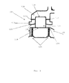
- FIG. 4 Another embodiment of a bearing cage 110 is shown in Fig. 4 . As discussed below, two additional, optional, features are included in the bearing cage 110 according to this embodiment: one or more barrier members 132 and one or more conduits 134.
- a bearing cage 110 typically includes one or more barrier members.
- a barrier member 132 is a member which projects from the bearing cage 110, preferably from the inner surface 130, towards the bore axis.
- the barrier members 132 act as a barrier to help prevent lubricant on the inner surface 130 of the bearing cage 110 from dispersing in a direction away from the central region of the bore, and thereby promoting the lubricant to disperse in the direction of the central region of the bore.
- the barrier member(s) 132 provide a physical barrier to block progression of lubricant along the inner surface 130, in the axial direction of the bore, away from the central region of the bore.
- a respective barrier member may be provided for each taper.
- the or each barrier member is arranged so that its respective taper is located between the barrier member and the central region of the bore.
- the or each barrier member is preferably located axially outwards from the central region of the bore and from its respective taper.
- each tapered bore may be located (in the axial direction of the bore) between a barrier member and the central region of the bearing cage 110.
- the barrier member may be formed as a radially inwardly projecting lip at the edge of the bore, e.g. at each end of the bore.
- the lip extends radially inwardly of the inner surface of the cage sufficiently to ensure the volume of oil entrained in the bore of the bearing cage does not flow over the lip.
- the actual size of the lip i.e. the extent of radial projection
- a number of lubricant holes or conduits could be added through the bearing cage to provide a direct lubricant feed to the pilot surfaces, i.e. to the pilot interface formed between the respective pilot surfaces of the bearing cage and the outer body.
- the size and number of these holes is dependent on the required level of lubricant flow to pass directly to the cage pilot lands. This can be calculated using standard fluid dynamics theory. The size and number of the oil holes would be restricted by the size of the cage to ensure that structural integrity of the cage is maintained.
- FIG. 4 Another feature of the present invention shown in the embodiment described by Fig. 4 is the one or more conduits 134, putting the inner and outer surfaces of the bearing cage 110 in fluid communication with one another.
- Lubricant on inner surface 130 of the bearing cage 110 is able to pass along each conduit 134 in order to arrive at the outer surface of the bearing cage 110, and thereby lubricate the cage pilot surface 108a and/or the pilot surface of the outer body 108.
- the conduits may be arranged to extend radially with respect to the axis of the bore, and thus with respect to the principal axis of the assembly.
- Each set of conduits 134 may include a first pair of conduits, the respective pocket preferably being located between the first pair of conduits in the axial direction of the bore of the bearing cage 110.
- each pocket is provided with a respective conduit which includes an opening on the inner surface of bearing cage 110 located in a region of the inner surface partly defining a tapered region of the bore.
- conduits are provided having an opening (or aperture) located in the region of taper of the bore, e.g. in the guide region of the bore.
- each pocket is provided with a respective set of conduits including a pair of conduits, each conduit of the pair having an opening formed in a respective region of the inner surface of the cage bearing 110, each of these respective regions of the inner surface of the cage bearing 110 partly defining a respective tapered (sub) bore of the bearing cage bore.
- conduit 134 is provided in a bearing cage 110 together with a barrier member 132, preferably the conduit is located between a pocket 120 formed in the bearing cage 110 and the barrier member, with respect to the axial direction of the bore.
- the conduit is typically greater than 1 mm in diameter, and is typically chosen to ensure a reliable flow of lubricant.
- the long axis of the or each conduit is formed to extend substantially orthogonally to the long axis of the bore of the bearing cage 110.
- the long axis of the or each conduit is preferably parallel to a radius of the bore of the bearing cage 110.
- the opening or aperture formed in the inner surface of bearing cage 110 is offset, in the axial direction of the bore and/or circumferentially around the bore, with respect to the location of openings 124 of lubricant (oil) feeders 126.
- the axial length of the bearing cage 110 may exceed that of the inner body 106 and/or outer body 108 in either or both axial directions.
- each lubricant (oil) feed opening 124 provided by the inner body is located within the bore, and thus the cage bearing extends in the axial direction beyond the lubricant (oil) feed openings.
- the extent to which the cage bearing extends in the axial direction beyond the lubricant (oil) feed openings 124 will depend on the relative axial movement between the inner body 106 and outer body 108, and thus between the inner body 106 and outer body 108, because axial movement of the outer body 108 typically results in a corresponding axial movement of bearing cage 110.
- bore has been used herein, methods other than boring could be used to form the bore, for example, machining other than boring, moulding, casting, etching, laser cutting, etc. could be used to form a bearing cage having an inner surface defining a bore.
- the term lumen could be used in place of bore.
Landscapes
- Engineering & Computer Science (AREA)
- General Engineering & Computer Science (AREA)
- Mechanical Engineering (AREA)
- Chemical & Material Sciences (AREA)
- Combustion & Propulsion (AREA)
- Rolling Contact Bearings (AREA)
Applications Claiming Priority (1)
| Application Number | Priority Date | Filing Date | Title |
|---|---|---|---|
| GB201314050A GB201314050D0 (en) | 2013-08-06 | 2013-08-06 | Tapered oil feed bearing cage |
Publications (3)
| Publication Number | Publication Date |
|---|---|
| EP2835545A2 true EP2835545A2 (de) | 2015-02-11 |
| EP2835545A3 EP2835545A3 (de) | 2015-06-03 |
| EP2835545B1 EP2835545B1 (de) | 2019-12-11 |
Family
ID=49224227
Family Applications (1)
| Application Number | Title | Priority Date | Filing Date |
|---|---|---|---|
| EP14176997.6A Active EP2835545B1 (de) | 2013-08-06 | 2014-07-15 | Käfig mit Ölumlaufschmierungseinrichtungen |
Country Status (3)
| Country | Link |
|---|---|
| US (1) | US9194432B2 (de) |
| EP (1) | EP2835545B1 (de) |
| GB (1) | GB201314050D0 (de) |
Cited By (2)
| Publication number | Priority date | Publication date | Assignee | Title |
|---|---|---|---|---|
| CN110685999A (zh) * | 2019-09-27 | 2020-01-14 | 南京荧河谷科技有限公司 | 一种常温循环油润滑轴承 |
| EP3109514B1 (de) * | 2015-06-25 | 2021-10-06 | Raytheon Technologies Corporation | Wälzkörperkäfig für getriebeturbolüfter |
Families Citing this family (7)
| Publication number | Priority date | Publication date | Assignee | Title |
|---|---|---|---|---|
| DE102013207494A1 (de) * | 2013-04-25 | 2014-10-30 | Schaeffler Technologies Gmbh & Co. Kg | Wälzlagerkäfig für ein Radiallager |
| GB2537400A (en) * | 2015-04-16 | 2016-10-19 | Skf Ab | Rolling element bearing |
| US10458270B2 (en) | 2015-06-23 | 2019-10-29 | United Technologies Corporation | Roller bearings for high ratio geared turbofan engine |
| GB201519892D0 (en) * | 2015-11-11 | 2015-12-23 | Rolls Royce Plc | A bearing arrangement and a bearing cage |
| US9909621B2 (en) * | 2016-02-23 | 2018-03-06 | Schaeffler Technologies AG & Co. KG | Bearing with integral grease groove reservoirs |
| US10451113B2 (en) * | 2017-05-18 | 2019-10-22 | General Electric Company | Bearing cages for roller bearing assemblies |
| DE102020116785B4 (de) * | 2020-06-25 | 2025-01-23 | Rolls-Royce Deutschland Ltd & Co Kg | Strukturbaugruppe für ein Gasturbinentriebwerk |
Family Cites Families (14)
| Publication number | Priority date | Publication date | Assignee | Title |
|---|---|---|---|---|
| US2838348A (en) * | 1956-04-17 | 1958-06-10 | Gen Electric | High speed anti-friction bearings |
| US3179478A (en) * | 1963-02-11 | 1965-04-20 | Massachusetts Inst Technology | Ball bearing and retainer therefor |
| GB1200408A (en) * | 1968-08-29 | 1970-07-29 | Rolls Royce | Bearing |
| GB2073828B (en) * | 1980-04-08 | 1983-09-14 | Rolls Royce | Bearings |
| NL8501411A (nl) | 1985-05-15 | 1986-12-01 | Skf Ind Trading & Dev | Afdichting voor een aslager. |
| US4932500A (en) * | 1989-08-21 | 1990-06-12 | Honeywell Inc. | Lubrication insertion system |
| DE10343881B4 (de) * | 2003-09-23 | 2012-01-26 | Schaeffler Technologies Gmbh & Co. Kg | Kugellager |
| JP2006329218A (ja) * | 2005-05-23 | 2006-12-07 | Ntn Corp | 転がり軸受用保持器 |
| JP2007040512A (ja) * | 2005-06-29 | 2007-02-15 | Nsk Ltd | 円錐ころ軸受 |
| US8235599B2 (en) | 2008-02-25 | 2012-08-07 | United Technologies Corp. | Hydrodynamic tapered roller bearings and gas turbine engine systems involving such bearings |
| CN102007311B (zh) * | 2008-06-17 | 2013-12-11 | 株式会社捷太格特 | 圆柱滚子轴承 |
| JP5760470B2 (ja) * | 2011-02-09 | 2015-08-12 | 株式会社ジェイテクト | 車輪用転がり軸受装置 |
| US8979383B2 (en) * | 2011-10-10 | 2015-03-17 | General Electric Company | Dynamically-lubricated bearing and method of dynamically lubricating a bearing |
| JP5610013B2 (ja) * | 2013-03-11 | 2014-10-22 | 株式会社ジェイテクト | 円筒ころ軸受 |
-
2013
- 2013-08-06 GB GB201314050A patent/GB201314050D0/en not_active Ceased
-
2014
- 2014-07-15 EP EP14176997.6A patent/EP2835545B1/de active Active
- 2014-07-16 US US14/332,435 patent/US9194432B2/en active Active
Cited By (2)
| Publication number | Priority date | Publication date | Assignee | Title |
|---|---|---|---|---|
| EP3109514B1 (de) * | 2015-06-25 | 2021-10-06 | Raytheon Technologies Corporation | Wälzkörperkäfig für getriebeturbolüfter |
| CN110685999A (zh) * | 2019-09-27 | 2020-01-14 | 南京荧河谷科技有限公司 | 一种常温循环油润滑轴承 |
Also Published As
| Publication number | Publication date |
|---|---|
| US9194432B2 (en) | 2015-11-24 |
| EP2835545A3 (de) | 2015-06-03 |
| US20150043851A1 (en) | 2015-02-12 |
| EP2835545B1 (de) | 2019-12-11 |
| GB201314050D0 (en) | 2013-09-18 |
Similar Documents
| Publication | Publication Date | Title |
|---|---|---|
| EP2835545B1 (de) | Käfig mit Ölumlaufschmierungseinrichtungen | |
| EP3575620B1 (de) | Einreihiges kugellager mit integriertem squeeze-film-dämpfer | |
| US8562224B2 (en) | Bearing oiling system | |
| CN106838010B (zh) | 一种航空发动机的主轴承保持装置组件及航空发动机 | |
| US8529135B2 (en) | Angular contact ball bearing | |
| EP2133513B1 (de) | Lageranordnung | |
| US20190211874A1 (en) | Bearing device, and spidle device for machine tool | |
| US20110064340A1 (en) | Method and apparatus for stabilizing a squeeze film damper for a rotating machine | |
| EP2479446A2 (de) | Lagerring für ein Wälzlager | |
| US9181981B2 (en) | Bearing system and method for lubrication | |
| EP2835544B1 (de) | Lagerkäfigdeflektor | |
| US10174791B2 (en) | Ball bearing assembly with inner ring and lubrication therefor | |
| US10451114B1 (en) | Inner ring for a bearing and method for proportioning lubricant to a bearing | |
| EP3699447B1 (de) | Lager zur verwendung in hochgeschwindigkeitsanwendungen | |
| US10876578B2 (en) | Bearing assembly with inner rings and method of alignment | |
| US11473624B1 (en) | Bearing lubrication system and method of lubricating a duplex bearing | |
| CN203230740U (zh) | 带有润滑剂供给机构的滚动轴承装置 | |
| US11162535B2 (en) | Bearing for use in high speed application | |
| US10196981B2 (en) | Bearing raceway and a method of manufacturing a bearing | |
| JP2006316933A (ja) | 転がり軸受 |
Legal Events
| Date | Code | Title | Description |
|---|---|---|---|
| PUAI | Public reference made under article 153(3) epc to a published international application that has entered the european phase |
Free format text: ORIGINAL CODE: 0009012 |
|
| 17P | Request for examination filed |
Effective date: 20140715 |
|
| AK | Designated contracting states |
Kind code of ref document: A2 Designated state(s): AL AT BE BG CH CY CZ DE DK EE ES FI FR GB GR HR HU IE IS IT LI LT LU LV MC MK MT NL NO PL PT RO RS SE SI SK SM TR |
|
| AX | Request for extension of the european patent |
Extension state: BA ME |
|
| PUAL | Search report despatched |
Free format text: ORIGINAL CODE: 0009013 |
|
| AK | Designated contracting states |
Kind code of ref document: A3 Designated state(s): AL AT BE BG CH CY CZ DE DK EE ES FI FR GB GR HR HU IE IS IT LI LT LU LV MC MK MT NL NO PL PT RO RS SE SI SK SM TR |
|
| AX | Request for extension of the european patent |
Extension state: BA ME |
|
| RIC1 | Information provided on ipc code assigned before grant |
Ipc: F16C 33/46 20060101ALI20150428BHEP Ipc: F16C 19/06 20060101ALI20150428BHEP Ipc: F16C 33/38 20060101ALI20150428BHEP Ipc: F16C 33/58 20060101ALI20150428BHEP Ipc: F16C 33/66 20060101AFI20150428BHEP |
|
| RAP1 | Party data changed (applicant data changed or rights of an application transferred) |
Owner name: ROLLS-ROYCE PLC |
|
| R17P | Request for examination filed (corrected) |
Effective date: 20150902 |
|
| RBV | Designated contracting states (corrected) |
Designated state(s): AL AT BE BG CH CY CZ DE DK EE ES FI FR GB GR HR HU IE IS IT LI LT LU LV MC MK MT NL NO PL PT RO RS SE SI SK SM TR |
|
| STAA | Information on the status of an ep patent application or granted ep patent |
Free format text: STATUS: EXAMINATION IS IN PROGRESS |
|
| 17Q | First examination report despatched |
Effective date: 20170926 |
|
| GRAP | Despatch of communication of intention to grant a patent |
Free format text: ORIGINAL CODE: EPIDOSNIGR1 |
|
| STAA | Information on the status of an ep patent application or granted ep patent |
Free format text: STATUS: GRANT OF PATENT IS INTENDED |
|
| INTG | Intention to grant announced |
Effective date: 20191002 |
|
| GRAS | Grant fee paid |
Free format text: ORIGINAL CODE: EPIDOSNIGR3 |
|
| GRAA | (expected) grant |
Free format text: ORIGINAL CODE: 0009210 |
|
| STAA | Information on the status of an ep patent application or granted ep patent |
Free format text: STATUS: THE PATENT HAS BEEN GRANTED |
|
| AK | Designated contracting states |
Kind code of ref document: B1 Designated state(s): AL AT BE BG CH CY CZ DE DK EE ES FI FR GB GR HR HU IE IS IT LI LT LU LV MC MK MT NL NO PL PT RO RS SE SI SK SM TR |
|
| REG | Reference to a national code |
Ref country code: GB Ref legal event code: FG4D |
|
| REG | Reference to a national code |
Ref country code: CH Ref legal event code: EP |
|
| REG | Reference to a national code |
Ref country code: AT Ref legal event code: REF Ref document number: 1212485 Country of ref document: AT Kind code of ref document: T Effective date: 20191215 |
|
| REG | Reference to a national code |
Ref country code: DE Ref legal event code: R096 Ref document number: 602014058145 Country of ref document: DE |
|
| REG | Reference to a national code |
Ref country code: IE Ref legal event code: FG4D |
|
| RAP2 | Party data changed (patent owner data changed or rights of a patent transferred) |
Owner name: ROLLS-ROYCE PLC |
|
| REG | Reference to a national code |
Ref country code: NL Ref legal event code: MP Effective date: 20191211 |
|
| REG | Reference to a national code |
Ref country code: LT Ref legal event code: MG4D |
|
| PG25 | Lapsed in a contracting state [announced via postgrant information from national office to epo] |
Ref country code: LT Free format text: LAPSE BECAUSE OF FAILURE TO SUBMIT A TRANSLATION OF THE DESCRIPTION OR TO PAY THE FEE WITHIN THE PRESCRIBED TIME-LIMIT Effective date: 20191211 Ref country code: NO Free format text: LAPSE BECAUSE OF FAILURE TO SUBMIT A TRANSLATION OF THE DESCRIPTION OR TO PAY THE FEE WITHIN THE PRESCRIBED TIME-LIMIT Effective date: 20200311 Ref country code: GR Free format text: LAPSE BECAUSE OF FAILURE TO SUBMIT A TRANSLATION OF THE DESCRIPTION OR TO PAY THE FEE WITHIN THE PRESCRIBED TIME-LIMIT Effective date: 20200312 Ref country code: ES Free format text: LAPSE BECAUSE OF FAILURE TO SUBMIT A TRANSLATION OF THE DESCRIPTION OR TO PAY THE FEE WITHIN THE PRESCRIBED TIME-LIMIT Effective date: 20191211 Ref country code: FI Free format text: LAPSE BECAUSE OF FAILURE TO SUBMIT A TRANSLATION OF THE DESCRIPTION OR TO PAY THE FEE WITHIN THE PRESCRIBED TIME-LIMIT Effective date: 20191211 Ref country code: BG Free format text: LAPSE BECAUSE OF FAILURE TO SUBMIT A TRANSLATION OF THE DESCRIPTION OR TO PAY THE FEE WITHIN THE PRESCRIBED TIME-LIMIT Effective date: 20200311 Ref country code: SE Free format text: LAPSE BECAUSE OF FAILURE TO SUBMIT A TRANSLATION OF THE DESCRIPTION OR TO PAY THE FEE WITHIN THE PRESCRIBED TIME-LIMIT Effective date: 20191211 Ref country code: LV Free format text: LAPSE BECAUSE OF FAILURE TO SUBMIT A TRANSLATION OF THE DESCRIPTION OR TO PAY THE FEE WITHIN THE PRESCRIBED TIME-LIMIT Effective date: 20191211 |
|
| PG25 | Lapsed in a contracting state [announced via postgrant information from national office to epo] |
Ref country code: HR Free format text: LAPSE BECAUSE OF FAILURE TO SUBMIT A TRANSLATION OF THE DESCRIPTION OR TO PAY THE FEE WITHIN THE PRESCRIBED TIME-LIMIT Effective date: 20191211 Ref country code: RS Free format text: LAPSE BECAUSE OF FAILURE TO SUBMIT A TRANSLATION OF THE DESCRIPTION OR TO PAY THE FEE WITHIN THE PRESCRIBED TIME-LIMIT Effective date: 20191211 |
|
| PG25 | Lapsed in a contracting state [announced via postgrant information from national office to epo] |
Ref country code: AL Free format text: LAPSE BECAUSE OF FAILURE TO SUBMIT A TRANSLATION OF THE DESCRIPTION OR TO PAY THE FEE WITHIN THE PRESCRIBED TIME-LIMIT Effective date: 20191211 |
|
| PG25 | Lapsed in a contracting state [announced via postgrant information from national office to epo] |
Ref country code: CZ Free format text: LAPSE BECAUSE OF FAILURE TO SUBMIT A TRANSLATION OF THE DESCRIPTION OR TO PAY THE FEE WITHIN THE PRESCRIBED TIME-LIMIT Effective date: 20191211 Ref country code: PT Free format text: LAPSE BECAUSE OF FAILURE TO SUBMIT A TRANSLATION OF THE DESCRIPTION OR TO PAY THE FEE WITHIN THE PRESCRIBED TIME-LIMIT Effective date: 20200506 Ref country code: RO Free format text: LAPSE BECAUSE OF FAILURE TO SUBMIT A TRANSLATION OF THE DESCRIPTION OR TO PAY THE FEE WITHIN THE PRESCRIBED TIME-LIMIT Effective date: 20191211 Ref country code: NL Free format text: LAPSE BECAUSE OF FAILURE TO SUBMIT A TRANSLATION OF THE DESCRIPTION OR TO PAY THE FEE WITHIN THE PRESCRIBED TIME-LIMIT Effective date: 20191211 Ref country code: EE Free format text: LAPSE BECAUSE OF FAILURE TO SUBMIT A TRANSLATION OF THE DESCRIPTION OR TO PAY THE FEE WITHIN THE PRESCRIBED TIME-LIMIT Effective date: 20191211 |
|
| PG25 | Lapsed in a contracting state [announced via postgrant information from national office to epo] |
Ref country code: SK Free format text: LAPSE BECAUSE OF FAILURE TO SUBMIT A TRANSLATION OF THE DESCRIPTION OR TO PAY THE FEE WITHIN THE PRESCRIBED TIME-LIMIT Effective date: 20191211 Ref country code: IS Free format text: LAPSE BECAUSE OF FAILURE TO SUBMIT A TRANSLATION OF THE DESCRIPTION OR TO PAY THE FEE WITHIN THE PRESCRIBED TIME-LIMIT Effective date: 20200411 Ref country code: SM Free format text: LAPSE BECAUSE OF FAILURE TO SUBMIT A TRANSLATION OF THE DESCRIPTION OR TO PAY THE FEE WITHIN THE PRESCRIBED TIME-LIMIT Effective date: 20191211 |
|
| REG | Reference to a national code |
Ref country code: DE Ref legal event code: R097 Ref document number: 602014058145 Country of ref document: DE |
|
| REG | Reference to a national code |
Ref country code: AT Ref legal event code: MK05 Ref document number: 1212485 Country of ref document: AT Kind code of ref document: T Effective date: 20191211 |
|
| PLBE | No opposition filed within time limit |
Free format text: ORIGINAL CODE: 0009261 |
|
| STAA | Information on the status of an ep patent application or granted ep patent |
Free format text: STATUS: NO OPPOSITION FILED WITHIN TIME LIMIT |
|
| PG25 | Lapsed in a contracting state [announced via postgrant information from national office to epo] |
Ref country code: DK Free format text: LAPSE BECAUSE OF FAILURE TO SUBMIT A TRANSLATION OF THE DESCRIPTION OR TO PAY THE FEE WITHIN THE PRESCRIBED TIME-LIMIT Effective date: 20191211 |
|
| 26N | No opposition filed |
Effective date: 20200914 |
|
| PG25 | Lapsed in a contracting state [announced via postgrant information from national office to epo] |
Ref country code: AT Free format text: LAPSE BECAUSE OF FAILURE TO SUBMIT A TRANSLATION OF THE DESCRIPTION OR TO PAY THE FEE WITHIN THE PRESCRIBED TIME-LIMIT Effective date: 20191211 Ref country code: PL Free format text: LAPSE BECAUSE OF FAILURE TO SUBMIT A TRANSLATION OF THE DESCRIPTION OR TO PAY THE FEE WITHIN THE PRESCRIBED TIME-LIMIT Effective date: 20191211 Ref country code: SI Free format text: LAPSE BECAUSE OF FAILURE TO SUBMIT A TRANSLATION OF THE DESCRIPTION OR TO PAY THE FEE WITHIN THE PRESCRIBED TIME-LIMIT Effective date: 20191211 |
|
| PG25 | Lapsed in a contracting state [announced via postgrant information from national office to epo] |
Ref country code: IT Free format text: LAPSE BECAUSE OF FAILURE TO SUBMIT A TRANSLATION OF THE DESCRIPTION OR TO PAY THE FEE WITHIN THE PRESCRIBED TIME-LIMIT Effective date: 20191211 |
|
| PG25 | Lapsed in a contracting state [announced via postgrant information from national office to epo] |
Ref country code: MC Free format text: LAPSE BECAUSE OF FAILURE TO SUBMIT A TRANSLATION OF THE DESCRIPTION OR TO PAY THE FEE WITHIN THE PRESCRIBED TIME-LIMIT Effective date: 20191211 |
|
| REG | Reference to a national code |
Ref country code: CH Ref legal event code: PL |
|
| REG | Reference to a national code |
Ref country code: BE Ref legal event code: MM Effective date: 20200731 |
|
| PG25 | Lapsed in a contracting state [announced via postgrant information from national office to epo] |
Ref country code: LI Free format text: LAPSE BECAUSE OF NON-PAYMENT OF DUE FEES Effective date: 20200731 Ref country code: CH Free format text: LAPSE BECAUSE OF NON-PAYMENT OF DUE FEES Effective date: 20200731 Ref country code: LU Free format text: LAPSE BECAUSE OF NON-PAYMENT OF DUE FEES Effective date: 20200715 |
|
| PG25 | Lapsed in a contracting state [announced via postgrant information from national office to epo] |
Ref country code: BE Free format text: LAPSE BECAUSE OF NON-PAYMENT OF DUE FEES Effective date: 20200731 |
|
| PG25 | Lapsed in a contracting state [announced via postgrant information from national office to epo] |
Ref country code: IE Free format text: LAPSE BECAUSE OF NON-PAYMENT OF DUE FEES Effective date: 20200715 |
|
| PG25 | Lapsed in a contracting state [announced via postgrant information from national office to epo] |
Ref country code: TR Free format text: LAPSE BECAUSE OF FAILURE TO SUBMIT A TRANSLATION OF THE DESCRIPTION OR TO PAY THE FEE WITHIN THE PRESCRIBED TIME-LIMIT Effective date: 20191211 Ref country code: MT Free format text: LAPSE BECAUSE OF FAILURE TO SUBMIT A TRANSLATION OF THE DESCRIPTION OR TO PAY THE FEE WITHIN THE PRESCRIBED TIME-LIMIT Effective date: 20191211 Ref country code: CY Free format text: LAPSE BECAUSE OF FAILURE TO SUBMIT A TRANSLATION OF THE DESCRIPTION OR TO PAY THE FEE WITHIN THE PRESCRIBED TIME-LIMIT Effective date: 20191211 |
|
| PG25 | Lapsed in a contracting state [announced via postgrant information from national office to epo] |
Ref country code: MK Free format text: LAPSE BECAUSE OF FAILURE TO SUBMIT A TRANSLATION OF THE DESCRIPTION OR TO PAY THE FEE WITHIN THE PRESCRIBED TIME-LIMIT Effective date: 20191211 |
|
| P01 | Opt-out of the competence of the unified patent court (upc) registered |
Effective date: 20230528 |
|
| PGFP | Annual fee paid to national office [announced via postgrant information from national office to epo] |
Ref country code: DE Payment date: 20250728 Year of fee payment: 12 |
|
| PGFP | Annual fee paid to national office [announced via postgrant information from national office to epo] |
Ref country code: GB Payment date: 20250722 Year of fee payment: 12 |
|
| PGFP | Annual fee paid to national office [announced via postgrant information from national office to epo] |
Ref country code: FR Payment date: 20250725 Year of fee payment: 12 |