EP2834707B1 - Höhenverstellbares gestell für einen bildschirm oder eine anzeige - Google Patents
Höhenverstellbares gestell für einen bildschirm oder eine anzeige Download PDFInfo
- Publication number
- EP2834707B1 EP2834707B1 EP13771974.6A EP13771974A EP2834707B1 EP 2834707 B1 EP2834707 B1 EP 2834707B1 EP 13771974 A EP13771974 A EP 13771974A EP 2834707 B1 EP2834707 B1 EP 2834707B1
- Authority
- EP
- European Patent Office
- Prior art keywords
- base
- stand
- surface part
- beams
- movable structure
- Prior art date
- Legal status (The legal status is an assumption and is not a legal conclusion. Google has not performed a legal analysis and makes no representation as to the accuracy of the status listed.)
- Not-in-force
Links
Images




Classifications
-
- F—MECHANICAL ENGINEERING; LIGHTING; HEATING; WEAPONS; BLASTING
- F16—ENGINEERING ELEMENTS AND UNITS; GENERAL MEASURES FOR PRODUCING AND MAINTAINING EFFECTIVE FUNCTIONING OF MACHINES OR INSTALLATIONS; THERMAL INSULATION IN GENERAL
- F16M—FRAMES, CASINGS OR BEDS OF ENGINES, MACHINES OR APPARATUS, NOT SPECIFIC TO ENGINES, MACHINES OR APPARATUS PROVIDED FOR ELSEWHERE; STANDS; SUPPORTS
- F16M11/00—Stands or trestles as supports for apparatus or articles placed thereon ; Stands for scientific apparatus such as gravitational force meters
- F16M11/02—Heads
- F16M11/04—Means for attachment of apparatus; Means allowing adjustment of the apparatus relatively to the stand
- F16M11/043—Allowing translations
- F16M11/046—Allowing translations adapted to upward-downward translation movement
-
- F—MECHANICAL ENGINEERING; LIGHTING; HEATING; WEAPONS; BLASTING
- F16—ENGINEERING ELEMENTS AND UNITS; GENERAL MEASURES FOR PRODUCING AND MAINTAINING EFFECTIVE FUNCTIONING OF MACHINES OR INSTALLATIONS; THERMAL INSULATION IN GENERAL
- F16M—FRAMES, CASINGS OR BEDS OF ENGINES, MACHINES OR APPARATUS, NOT SPECIFIC TO ENGINES, MACHINES OR APPARATUS PROVIDED FOR ELSEWHERE; STANDS; SUPPORTS
- F16M11/00—Stands or trestles as supports for apparatus or articles placed thereon ; Stands for scientific apparatus such as gravitational force meters
- F16M11/20—Undercarriages with or without wheels
- F16M11/24—Undercarriages with or without wheels changeable in height or length of legs, also for transport only, e.g. by means of tubes screwed into each other
-
- F—MECHANICAL ENGINEERING; LIGHTING; HEATING; WEAPONS; BLASTING
- F16—ENGINEERING ELEMENTS AND UNITS; GENERAL MEASURES FOR PRODUCING AND MAINTAINING EFFECTIVE FUNCTIONING OF MACHINES OR INSTALLATIONS; THERMAL INSULATION IN GENERAL
- F16M—FRAMES, CASINGS OR BEDS OF ENGINES, MACHINES OR APPARATUS, NOT SPECIFIC TO ENGINES, MACHINES OR APPARATUS PROVIDED FOR ELSEWHERE; STANDS; SUPPORTS
- F16M11/00—Stands or trestles as supports for apparatus or articles placed thereon ; Stands for scientific apparatus such as gravitational force meters
- F16M11/02—Heads
- F16M11/18—Heads with mechanism for moving the apparatus relatively to the stand
-
- F—MECHANICAL ENGINEERING; LIGHTING; HEATING; WEAPONS; BLASTING
- F16—ENGINEERING ELEMENTS AND UNITS; GENERAL MEASURES FOR PRODUCING AND MAINTAINING EFFECTIVE FUNCTIONING OF MACHINES OR INSTALLATIONS; THERMAL INSULATION IN GENERAL
- F16M—FRAMES, CASINGS OR BEDS OF ENGINES, MACHINES OR APPARATUS, NOT SPECIFIC TO ENGINES, MACHINES OR APPARATUS PROVIDED FOR ELSEWHERE; STANDS; SUPPORTS
- F16M11/00—Stands or trestles as supports for apparatus or articles placed thereon ; Stands for scientific apparatus such as gravitational force meters
- F16M11/42—Stands or trestles as supports for apparatus or articles placed thereon ; Stands for scientific apparatus such as gravitational force meters with arrangement for propelling the support stands on wheels
-
- G—PHYSICS
- G03—PHOTOGRAPHY; CINEMATOGRAPHY; ANALOGOUS TECHNIQUES USING WAVES OTHER THAN OPTICAL WAVES; ELECTROGRAPHY; HOLOGRAPHY
- G03B—APPARATUS OR ARRANGEMENTS FOR TAKING PHOTOGRAPHS OR FOR PROJECTING OR VIEWING THEM; APPARATUS OR ARRANGEMENTS EMPLOYING ANALOGOUS TECHNIQUES USING WAVES OTHER THAN OPTICAL WAVES; ACCESSORIES THEREFOR
- G03B21/00—Projectors or projection-type viewers; Accessories therefor
- G03B21/54—Accessories
- G03B21/56—Projection screens
Definitions
- the present invention relates to a stand for a screen or a display. More specifically the present invention relates to a stand for a display or a projector screen and possibly also a short throw projector, which is to be arranged on the projector screen stand together with a screen.
- Short throw projectors are sometimes referred to as “ultra short throw projectors”.
- the term “short throw projector” will be used for both types of projectors.
- Such projectors can be placed at a short distance from the screen on which the images from the projector are projected.
- Such projectors are normally arranged on an arm which extends from the screen so that the projector and screen are arranged fixed in relation to each other.
- the screen and the projector may be arranged on a height adjustable stand so that the screen may be positioned at different heights above the surface on which the stand is arranged.
- Displays are available in a large number of different sizes and may also be provided with a touch sensitive surface to provide an interactive display.
- CA2748768A1 describes a stands for a screen and a projector for placement on a floor.
- US 2009/0166302 A1 describes an electrically controlled vertically adjustable flat panel display bracket.
- An object of the present invention is to provide a height adjustable stand for a projector screen or a display, which is an alternative to the stands according to the prior art.
- Another object of the present invention is to provide a height adjustable stand for a projector screen or a display, with which the risk for malfunction due to pinching of objects in the height adjustment mechanism is minimized.
- a further object of the present invention is to provide a height adjustable stand, for a projector screen or a display, with which the risk for injuries caused by squeezing is minimized.
- a height adjustable stand for a projector screen or a display comprises a base for arrangement on a floor, at least a first base beam with a first length axis and a second base beam with a second length axis, which length axes are essentially parallel and arranged to be essentially vertical when the base is arranged on a floor.
- the back sides of the base beams define a vertical back plane and the front sides of the base beams define a vertical front plane.
- the stand also comprises at least one base connecting member which connects the base beams, and a movable structure which is movable along the base beams and which is arranged between the front plane and the back plane.
- the stand is characterized in that the stand comprises at least a first front plate which is arranged with a first vertical slit between the front plate and the first base beam, and a second vertical slit between the front plate and the second base beam, at least a first back plate arranged to cover a majority of the area between the base beams, a mount arranged on the outside of the front plate and connected to the movable structure, and a first connecting means and a second connecting means arranged through the first slit and the second slit, respectively, wherein each connecting means is connected to the movable structure and the mount, which mount is arranged to receive the projector screen or the display.
- a front plate according to the invention By arranging a front plate according to the invention, so that only slits are open between the front plate and the base beams, the risk of people or material getting stuck or pinched between the movable structure and the base is minimized.
- the slits may be made very narrow while still providing sufficient strength for carrying the screen or display.
- the arrangement with a slit at each base beam provides for two connecting means. The provision of two connecting means also contributes to the sufficient combined strength of the connecting means.
- Each one of the connecting means may comprise at least one plate.
- Plates are favourable to use as connecting means as they may be arranged in a narrow slit, they are relatively cheap to provide and they provide a good stability in the plane. Two plates arranged at a distance from each other provides good stability for the mount. Narrow slits are also favourable in that the risk of pinching anything in the slit thereby is minimized.
- the back plate may be essentially flat and is arranged essentially in the back plane. This provides for a flat back surface as the back plate blends into the base beams. It is also possible to have the back plate curved.
- the front plate may be essentially flat and may be arranged essentially in the front plane. This provides for the mount to be arranged as close as possible to the base beams.
- the front plate seen towards the base beams perpendicular to the front plane, may be arranged to cover a part of both base beams at a distance from the base beams so that the slits seen in cross section are curved.
- each base beam in cross section may have a form comprising a main surface part, an inward surface part defining the beginning of the slit with a convex bend between the main surface part and the inward surface part and an inner surface part with a concave bend between the inward surface part and the inner surface part, wherein the front plate, seen towards the base beams perpendicular to the front plane, is arranged to cover the inner surface part at least partially.
- a form on the base beams provides for a smooth transition between the surfaces of the base beams to the plate.
- the inner surface part may be essentially flat and parallel to the front plane.
- the inward surface part is essentially flat and perpendicular to the front plane. This provides for easy manufacturing of the connecting means as the connecting means may be provided with bends in right angles.
- the movable structure comprises a first structure beam and a second structure beam, which are arranged suspended in the base beams, and at least one structure connecting member, which connects the structure beams. It is possible to arrange the movable structure in other ways but by using structure beams the construction of the movable structure is facilitated.
- the structure beams as well as the base beams may be extruded.
- the stand may comprise actuating means which is arranged to provide an upward force on the movable structure in relation to the base. By providing such actuating means the movable structure may be moved up and down along the base beams.
- the actuating means may be arranged to provide a force between the base connecting member and the structure connecting member. It is of course possible to arrange the actuating means in other ways, but in this way the force from the actuating means may be centred to the centre of gravity of the movable structure and the display or the screen.
- the actuating means may comprise at least one screw, at least one nut member and at least one electrical motor which is arranged to drive at least one of said at least one screw and said at least one nut member.
- the actuating means may be arranged between the front plate and the back plate said at least one screw does not have to be covered but may be exposed between the motor and the nut member.
- the nut member may be only a nut or a tube with a nut arranged in the tube.
- the screw may be arranged on the base and may be arranged to be driven by the electrical motor and the nut member may be arranged on the movable member. It is favourable to have the motor on the base member as the electrical cables to the motor then does not have to move in relation to the movable structure.
- the actuating means may comprise at least one roll formed coil spring which is arranged to provide an upwardly directed force on the movable member in relation to the base. This is an alternative to the use of an electrical motor, a screw and a nut.
- the roll formed coil springs may be arranged in a suitable number and strength to essentially balance the weight of the movable structure and the display. The friction force between the movable structure and the base should be sufficiently strong to allow the movable structure to be still when no force is applied to the movable structure.
- the movable structure may extend above the upper end of the first and second base beam, and the stand may comprise an upper mount arranged on the part of the movable structure extending above the upper end of the first and second base beam, which upper mount is arranged to receive the upper part of the projector screen or the display.
- the stand may be reasonably low in a transport position while still providing the possibility to have a large screen on the stand.
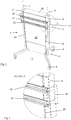
- Fig 1 is a front perspective view of a height adjustable stand 1 according to an embodiment of the present invention.
- Fig 2 is an enlargement of detail D in Fig 1 .
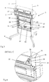
- Fig 3 is a front perspective view of the stand shown in Fig 1 , with a front plate removed.
- Fig 4 is an enlargement of detail C in Fig 3 .
- the height adjustable stand 1 comprises a mount 2 for reception of a display.
- the height adjustable stand comprises a base 3 with four wheels 4 for arrangement on a floor 5.
- the stand further comprises a first base beam 6 with a first length axis 7 and a second base beam 8 with a second length axis 9, which length axes 7, 9, are essentially parallel and arranged to be essentially vertical when the base 3 is arranged on a floor 5.
- the back sides of the base beams 6, 8, define a vertical back plane and the front sides of the base beams 6, 8, define a vertical front plane.
- Base connecting members in the form of a top transversal beam 10 and a mid transversal beam 11 connect the base beams 6, 8.
- the stand also comprises a movable structure 12 ( Fig 3 ) which is movable along the base beams 6, 8.
- the stand 1 also comprises at least a first front plate 13 which is arranged with a first vertical slit 14 between the front plate 13 and the first base beam 6, and a second vertical slit 15 between the front plate 13 and the second base beam 8.
- the stand also comprises a first back plate 16 ( Fig 3 ) arranged to cover a majority of the area between the base beams 6, 8.
- the movable structure is arranged between the front plane and the back plane and thus also between the first front plate 13 and the first back plate 16.
- the first front plate 13 and the first back plate 16 are essentially flat and coincide with the front plane and the back plane, respectively
- the mount 2 is arranged on the outside of the front plate 13 and connected to the movable structure 12 ( Fig 3 ).
- the stand 1 also comprises a first connecting means 18, and a second connecting means 19, arranged through the first slit 14 and the second slit 15, respectively, wherein each connecting means 18, 19, is connected to the movable structure 12 and the mount 2, which mount 2 comprises two horizontal rods 20, 21, on which a display is to be mounted.
- the connecting means 18, 19, are in the form of bent plates which can be seen most clearly in Fig 4 .
- the front plate 13, seen towards the base beams perpendicular to the front plane, is arranged to cover a part of both base beams 6, 8, at a distance from the base beams 6, 8, so that the slits 14, 15, seen in cross section is curved.
- Handles 17 are arranged attached to the horizontal rods 20, 21, and the connecting means. As a large portion of the mass of the stand and the display is concentrated to the movable structure it is favourable to have the handles 17 attached in this way.
- each base beam 6, 8, in cross section has a form comprising a main surface part 22, an inward surface part 23 defining the beginning of the slit 14, 15, with a convex bend 25 between the main surface part 22 and the inward surface part 23 and an inner surface part 24 with a concave bend 26 between the inward surface part 23 and the inner surface part 24, wherein the front plate 13, seen towards the base beams 6, 8, perpendicular to the front plane, is arranged to partially cover the inner surface part 24.
- the inner surface part 27 is essentially flat and parallel to the front plane and the inward surface part 23 is essentially flat and perpendicular to the front plane.
- the front plate 13 only covers a part of the inner surface part 26 and ends a small distance from the convex bend 25.
- the front plate 13 is also arranged a small distance from the inner surface part 27.
- the resulting slit 15 is L-formed.
- the plate formed connecting means 19 is also L-formed to fit in the slit 15.
- the movable structure 12 comprises a first structure beam 28 and a second structure beam 29, which are arranged suspended in the base beams. Rolls 30 are arranged on the first base beam to support the structure beams 28, 29, of the movable structure 12 so that the movement of the movable structure 12 is parallel to the front plane and the back plane.
- the movable structure 12 also comprises at least one structure connecting member 31, which connects the structure beams 28, 29.
- the base beams 6, 8, are provided with means 30 ( Fig 7 ) for providing a low friction between the structure beams 28, 29, and the base beams 6, 8.
- the means 30 may be plastic mats.
- the stand also comprises supporting means in the form of rolls 31 on which the structure beams 28, 29, may roll during their movement upwards and downwards along the base beams 6, 8.
- the stand 1 comprises actuating means comprising a first electrical motor 32, a first screw 33 which is arranged to be driven by the first electrical motor 32, and a first nut member 34 which is arranged to interact with the first screw 33.
- the actuating means also comprises a second electrical motor 35, a second screw 36 which is arranged to be driven by the second electrical motor 35, and a second nut member 37 which is arranged to interact with the second screw 36.
- the motors 32, 35 and screws 33, 36 are arranged on the mid transversal beam 11 of the base 3 while the nut members 34, 37, are arranged non-rotatable on the structure connecting member 31 of the movable structure 12.
- the motors 32, 35 are arranged to rotate the screws 33, 36 in relation to the non-rotatable nut members 34, 37. This will lead to a movement of the nut members 34, 37, in relation to the motors and thus also to a movement of the movable structure 12 in relation to the base 3.
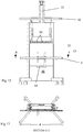
- Fig 5 is a front view of the stand 1 in Fig 1 .
- Fig 6 is a section along A-A in Fig 5 and
- Fig 7 is an enlargement of detail B in Fig 6 .
- a part of the inner surface part 24 is visible at the bottom of the slits 14, 15.
- the main surface part 22, the inward surface part 23 and the inner surface part 24 are shown in more detail.
- the convex bend 25 is a sharp 90 degree bend so that the inward surface part 23 is at a right angle to the front plate 13.
- the concave bend 26 is also a sharp 90 degree bend so that the inner surface part 24 is essentially parallel to the front plate 13.
- Fig 8 is a front perspective view of a stand 1 according to a second embodiment of the present invention.
- Fig 9 is an enlargement of detail C in Fig 8 .
- Fig 10 is a front perspective view of the stand 1 in Fig 8 with a front plate 13 removed.
- Fig 11 is an enlargement of detail D in Fig 10 .
- the stand according to this second embodiment of the invention is similar to the stand 1 according to the first embodiment.
- the actuating means comprises a number of roll formed coil springs 38 which are arranged to provide an upwardly directed force on the movable structure 12 in relation to the base 3.
- the force from said at least one roll formed coil spring 38 is balanced by the weight of the movable structure 12, the mount 2, the connecting means 19 and the display (not shown) together with the friction between the movable structure 12 and the base beams 6, 8, of the base 3.
- the roll formed coil springs 38 may of course be used also in the first embodiment instead of the motors 32, 35, screws 33, 36, and nut members 34, 37.
- the roll formed coil springs 38 are attached around an axle 39 which is attached to the base beams 6, 8, of the base 3.
- the roll formed coil springs 38 may either be rotatable in relation to the axle 39 or be fixed to the axle 39 which in turn is rotatable in relation to the base beams 6, 8.
- a plate 40 with a keyhole formed hole 41 is arranged in the outer end of each roll formed coil spring 38.
- the plates are to be connected to pins 45 arranged on the structure connecting member 31 of the movable structure 12. In Fig 10 none of the plates are connected to a pin 45.
- the stand according to the second embodiment comprises a first front plate 13 which defines the first slit 14 and the second slit 15 together with the base beams 6, 8.
- the stand also comprises a second front plate 46 on the lower part of the stand behind which second front plate 46 electronic equipment may be arranged. The top of the stand is open as this area is usually covered by a projector screen.
- a second main difference between the stand 1 according to the first embodiment and the stand 1 according to the second embodiment is that the movable structure 12 extends above the upper end of the first and second base beam 6, 8, and wherein the stand 1 comprises an upper mount 42 arranged on the part of the movable structure 12 extending above the upper end of the first and second base beam 6, 8, which upper mount 42 is arranged to receive the upper part of a projector screen (not shown).
- the stand also comprises a projector mount 43 arranged on the top of the movable structure 12, at the end 47 of which projector mount 43 a short throw projector (not shown) may be arranged.
- a handle 44 is arranged attached on the lower side of the mount 2.
- the connecting means 19 are a continuation of the structure connecting member 31. Also shown in Fig 11 is that the mount 2 only comprises one horizontal rod 20.
- Fig 12 is a front view of the stand in Fig 1 .
- Fig 13 is a section along A-A in Fig 12 .
- Fig 14 is an enlargement of detail B in Fig 13 .
Landscapes
- Engineering & Computer Science (AREA)
- General Engineering & Computer Science (AREA)
- Mechanical Engineering (AREA)
- Physics & Mathematics (AREA)
- General Physics & Mathematics (AREA)
- Devices For Indicating Variable Information By Combining Individual Elements (AREA)
- Projection Apparatus (AREA)
Claims (14)
- Höhenverstellbares Gestell (1) für einen Projektorbildschirm oder eine Anzeige, umfassend eine Basis (3) zur Anordnung auf einem Boden (5), wenigstens einen ersten Basisholm (6) mit einer ersten Längsachse (7) und einen zweiten Basisholm (8) mit einer zweiten Längsachse (9), wobei die Längsachsen (7, 9) im Wesentlichen parallel und so angeordnet sind, dass sie im Wesentlichen senkrecht verlaufen, wenn die Basis (3) auf dem Boden (5) angeordnet ist, wobei die Rückseiten der Basisholme (6, 8) eine senkrechte Rückebene festlegen und die Vorderseiten der Basisholme (6, 8) eine senkrechte Vorderebene festlegen, wenigstens ein Basisverbindungselement, das die Basisholme (6, 8) verbindet, und einen bewegbaren Aufbau (12), der entlang der Basisholme (6, 8) bewegt werden kann und zwischen der Vorderebene und der Rückebene angeordnet ist, wobei das Gestell (1) Folgendes umfasst:wenigstens eine erste Vorderplatte (13), die mit einem ersten senkrechten Schlitz (14) zwischen der Vorderplatte (13) und dem ersten Basisholm (6) und einem zweiten senkrechten Schlitz (15) zwischen der Vorderplatte (13) und dem zweiten Basisholm (8) angeordnet ist,wenigstens eine erste Rückplatte (16), die so angeordnet ist, dass sie einen Großteil des Bereichs zwischen den Basisholmen (6, 8) bedeckt,eine Halterung (2), die auf der Außenseite der Vorderplatte (13) angeordnet und mit dem bewegbaren Aufbau (12) verbunden ist, undein erstes Verbindungsmittel (18) und ein zweites Verbindungsmittel (19), die durch den ersten Schlitz (14) beziehungsweise den zweiten Schlitz (15) angeordnet sind, wobei jedes Verbindungsmittel (18) mit dem bewegbaren Aufbau (19) und der Halterung (2) verbunden ist, wobei die Halterung (2) so angeordnet ist, dass sie den Projektorbildschirm oder die Anzeige aufnehmen kann, unddadurch gekennzeichnet, dass die Vorderplatte rechtwinklig zu der Vorderplatte in Richtung zu den Basisholmen (6, 8) gesehen so angeordnet ist, dass sie einen Teil beider Basisholme (6, 8) beabstandet von den Basisholmen (6, 8) bedeckt, so dass die Schlitze (14, 15) im Querschnitt gesehen gekrümmt sind.
- Gestell (1) nach Anspruch 1, wobei jedes Verbindungsmittel (18, 19) wenigstens eine Platte enthält.
- Gestell (1) nach Anspruch 1 oder 2, wobei die Rückplatte (16) im Wesentlichen eben und im Wesentlichen in der Rückebene angeordnet ist.
- Gestell (1) nach Anspruch 1, 2 oder 3, wobei die Vorderplatte (13) im Wesentlichen eben und im Wesentlichen in der Vorderebene angeordnet ist.
- Gestell (1) nach einem der vorhergehenden Ansprüche, wobei die Vorderseite jedes Basisholms (6, 8) im Querschnitt eine Form aufweist, die einen Hauptflächenteil (22), einen nach innen gerichteten Flächenteil (23), der den Anfang des Schlitzes (14, 15) mit einer konvexen Biegung (25) zwischen dem Hauptflächenteil (22) und dem nach innen gerichteten Flächenteil (23) festlegt, und einen inneren Flächenteil (24) mit einer konkaven Biegung (26) zwischen dem nach innen gerichteten Flächenteil (23) und dem inneren Flächenteil (24) umfasst, wobei die Vorderplatte (13) rechtwinklig zu der Vorderebene in Richtung zu den Basisholmen (6, 8) gesehen so angeordnet ist, dass sie den inneren Flächenteil (24) wenigstens teilweise abdeckt.
- Gestell (1) nach Anspruch 5, wobei der innere Flächenteil (24) im Wesentlichen eben ist und parallel zu der Vorderebene verläuft.
- Gestell (1) nach Anspruch 5 oder 6, wobei der nach innen gerichtete Flächenteil (23) im Wesentlichen eben ist und rechtwinklig zu der Vorderebene verläuft.
- Gestell (1) nach einem der vorhergehenden Ansprüche, wobei der bewegbare Aufbau (12) einen ersten Aufbauholm (28) und einen zweiten Aufbauholm (29), die aufgehängt in den Basisholmen (6, 8) angeordnet sind, und wenigstens ein Aufbauverbindungselement (31) umfasst, das die Aufbauholme (28, 29) verbindet.
- Gestell (1) nach Anspruch 8, ein Betätigungsmittel umfassend, das so angeordnet ist, dass es eine nach oben gerichtete Kraft an dem bewegbaren Aufbau (12) relativ zu der Basis (3) vorsieht.
- Gestell (1) nach Anspruch 9, wobei das Betätigungsmittel so angeordnet ist, dass es eine Kraft zwischen dem Basisverbindungsmittel und dem Aufbauverbindungselement (31) vorsieht.
- Gestell (1) nach Anspruch 9 oder 10, wobei das Betätigungsmittel wenigstens eine Schraube (33, 36), wenigstens ein Mutterelement (34, 37) und wenigstens einen Elektromotor (32, 35) umfasst, der so angeordnet ist, dass er die wenigstens eine Schraube (33, 36) und/oder das wenigstens eine Mutterelement (34, 37) antreibt.
- Gestell (1) nach Anspruch 11, wobei die wenigstens eine Schraube (33, 36) auf der Basis (3) angeordnet ist und so angeordnet ist, dass sie von dem wenigstens einen Elektromotor (32, 25) angetrieben wird, und das Mutterelement (34, 37) an dem bewegbaren Aufbau (12) angeordnet ist.
- Gestell (1) nach Anspruch 9 oder 10, wobei das Betätigungsmittel wenigstens eine walzenförmige Spiralfeder (38) umfasst, die so angeordnet ist, dass sie eine nach oben gerichtete Kraft an dem bewegbaren Aufbau (12) relativ zu der Basis (3) vorsieht.
- Gestell (1) nach einem der vorhergehenden Ansprüche, wobei sich der bewegbare Aufbau (12) über dem oberen Ende des ersten und des zweiten Basisholms (6, 8) erstreckt und wobei das Gestell (1) eine obere Halterung (42) umfasst, die an dem Teil des bewegbaren Aufbaus (12) angeordnet ist, der sich über dem oberen Ende des ersten und des zweiten Basisholms (6, 8) erstreckt, wobei die obere Halterung (42) so angeordnet ist, dass sie den oberen Teil des Projektorbildschirms oder der Anzeige aufnimmt.
Applications Claiming Priority (2)
| Application Number | Priority Date | Filing Date | Title |
|---|---|---|---|
| SE1250328A SE536406C2 (sv) | 2012-04-02 | 2012-04-02 | Höjdjusterbart stativ för skärm eller bildskärm |
| PCT/SE2013/050109 WO2013151475A1 (en) | 2012-04-02 | 2013-02-11 | Height adjustable stand for screen or display |
Publications (3)
| Publication Number | Publication Date |
|---|---|
| EP2834707A1 EP2834707A1 (de) | 2015-02-11 |
| EP2834707A4 EP2834707A4 (de) | 2015-12-09 |
| EP2834707B1 true EP2834707B1 (de) | 2017-06-21 |
Family
ID=49274117
Family Applications (1)
| Application Number | Title | Priority Date | Filing Date |
|---|---|---|---|
| EP13771974.6A Not-in-force EP2834707B1 (de) | 2012-04-02 | 2013-02-11 | Höhenverstellbares gestell für einen bildschirm oder eine anzeige |
Country Status (4)
| Country | Link |
|---|---|
| US (1) | US9169960B2 (de) |
| EP (1) | EP2834707B1 (de) |
| SE (1) | SE536406C2 (de) |
| WO (1) | WO2013151475A1 (de) |
Families Citing this family (9)
| Publication number | Priority date | Publication date | Assignee | Title |
|---|---|---|---|---|
| US9791093B2 (en) * | 2013-10-11 | 2017-10-17 | Canon Finetech Nisca Inc. | Load support mechanism |
| JP6410014B2 (ja) * | 2014-05-19 | 2018-10-24 | キヤノンファインテックニスカ株式会社 | 荷重支持機構 |
| US9926945B2 (en) * | 2015-06-10 | 2018-03-27 | Joseph A. McDonnell | Snap-together stand for a fan |
| CN105882238A (zh) * | 2016-05-13 | 2016-08-24 | 安庆师范学院 | 安装有投影幕的教学板 |
| NL2017632B1 (en) * | 2016-10-18 | 2018-04-26 | Dataflex Int B V | Office workplace system |
| US11458328B2 (en) * | 2018-10-22 | 2022-10-04 | Joovv, Inc. | Photobiomodulation therapy device accessories |
| US11474419B2 (en) * | 2019-09-06 | 2022-10-18 | Five-Star Audiovisual, Inc. | Modular projection systems and methods of using said systems |
| CN116043742B (zh) * | 2022-12-15 | 2024-07-12 | 江苏鑫瑞交通建设集团有限公司 | 一种高度调节结构及公路指示牌 |
| USD1113264S1 (en) * | 2024-04-18 | 2026-02-17 | Ningbo Tuotuo River Design Company | Display stand |
Family Cites Families (33)
| Publication number | Priority date | Publication date | Assignee | Title |
|---|---|---|---|---|
| US4662524A (en) * | 1983-01-31 | 1987-05-05 | Hill-Rom Company, Inc. | Medical service column and mounting bracket |
| US6189849B1 (en) * | 1998-05-06 | 2001-02-20 | Ergotron, Inc. | Lift system |
| US6111693A (en) | 1999-02-04 | 2000-08-29 | Chin Music, Llc | Projection screen with movable shutter |
| US7537184B1 (en) * | 2003-03-21 | 2009-05-26 | Numonica Corporation | Boom device for presentation appliances |
| US7195213B2 (en) * | 2003-03-31 | 2007-03-27 | O'sullivan Industries Inc. | Adjustable television stand |
| GB2401784B (en) * | 2003-05-23 | 2005-10-12 | Peter Ligertwood | Display unit floor stand |
| US7044423B2 (en) * | 2003-11-25 | 2006-05-16 | Wieslaw Bober | Compound lift device |
| US7036787B1 (en) | 2005-02-04 | 2006-05-02 | Taiwan Thick-Film Ind. Corp. | Display strut adjusting structure |
| US20060238086A1 (en) * | 2005-04-20 | 2006-10-26 | Kuo-Wei Lai | Structure of a monitor support device with height adjusting function |
| JP4707744B2 (ja) | 2005-08-26 | 2011-06-22 | プロメテアン リミテド | インタラクティブディスプレイシステムの設置 |
| DE102006012766B4 (de) * | 2006-03-17 | 2009-04-09 | Dräger Medical AG & Co. KG | Befestigungssystem für medizintechnische Geräte |
| TW200740350A (en) * | 2006-04-12 | 2007-10-16 | Benq Corp | Adjustable supporting apparatus |
| TW200738993A (en) * | 2006-04-12 | 2007-10-16 | Benq Corp | Adjustable height support apparatus and display with the same |
| US20080068784A1 (en) * | 2006-09-15 | 2008-03-20 | Bouissiere Michael F | Moveable Display Mount |
| GB2443159A (en) * | 2006-10-24 | 2008-04-30 | Colebrook Bosson Saunders Prod | A decorative floor-standing support for flat screen displays |
| GB0707013D0 (en) * | 2007-04-12 | 2007-05-23 | Primac Ltd | Support system |
| JP4582132B2 (ja) * | 2007-08-28 | 2010-11-17 | ソニー株式会社 | L字スタンド |
| US20090057501A1 (en) * | 2007-09-03 | 2009-03-05 | Ming Hug Huang | Display exhibition frame |
| US20090166302A1 (en) * | 2007-12-31 | 2009-07-02 | Chin-Jui Hung | Electrically controlled vertically adjustable flat panel display bracket |
| CN101481073B (zh) * | 2008-01-09 | 2012-03-14 | 鸿富锦精密工业(深圳)有限公司 | 升降机构及其气缸 |
| CN201202937Y (zh) * | 2008-05-27 | 2009-03-04 | 常州新区赛恩机电设备有限公司 | 电视机升降器 |
| DE102008026989B3 (de) * | 2008-06-05 | 2009-09-03 | Dräger Medical AG & Co. KG | Befestigungsvorrichtung, medizinisches Gerät und Gerätesystem mit einer solchen Befestigungsvorrichtung |
| US20100045943A1 (en) * | 2008-08-25 | 2010-02-25 | Peerless Industries, Inc. | Projector Mount |
| TWI372560B (en) * | 2009-04-08 | 2012-09-11 | Aopen Inc | Hanging device for display |
| US8505860B2 (en) * | 2010-03-24 | 2013-08-13 | Middle Atlantic Products, Inc. | Video screen mounting system |
| SE535940C2 (sv) * | 2010-07-16 | 2013-02-26 | Sms Smart Media Solutions Ab | Höjdjusterbart projektorskärmstöd |
| US20120200834A1 (en) | 2010-08-11 | 2012-08-09 | Copernicus Educational Products Inc. | Projector arm assembly for whiteboard stand |
| CA2713016A1 (en) | 2010-08-11 | 2012-02-11 | Copernicus Educational Products Inc. | Projector arm assembly for whiteboard stand |
| CN201876657U (zh) * | 2010-11-11 | 2011-06-22 | 宁波翔龙金属制品有限公司 | 投影架 |
| US20120261362A1 (en) * | 2011-04-14 | 2012-10-18 | Joseph Skull | Display support column |
| US20130168335A1 (en) * | 2012-01-04 | 2013-07-04 | Peerless Industries, Inc. | Moveable fixture for exhibiting display devices or the like |
| US8693093B2 (en) * | 2012-01-27 | 2014-04-08 | LeRoy Francis Kepley, JR. | Portable projector and screen mounting system |
| US9091393B2 (en) * | 2013-06-27 | 2015-07-28 | Ming Hua Huang | Lifting type support stand |
-
2012
- 2012-04-02 SE SE1250328A patent/SE536406C2/sv not_active IP Right Cessation
-
2013
- 2013-02-11 WO PCT/SE2013/050109 patent/WO2013151475A1/en not_active Ceased
- 2013-02-11 EP EP13771974.6A patent/EP2834707B1/de not_active Not-in-force
- 2013-02-11 US US14/389,904 patent/US9169960B2/en active Active
Also Published As
| Publication number | Publication date |
|---|---|
| EP2834707A4 (de) | 2015-12-09 |
| US9169960B2 (en) | 2015-10-27 |
| WO2013151475A1 (en) | 2013-10-10 |
| EP2834707A1 (de) | 2015-02-11 |
| US20150076311A1 (en) | 2015-03-19 |
| SE536406C2 (sv) | 2013-10-08 |
| SE1250328A1 (sv) | 2013-10-03 |
Similar Documents
| Publication | Publication Date | Title |
|---|---|---|
| US9169960B2 (en) | Height adjustable stand for screen or display | |
| US9625082B2 (en) | Simultaneously foldable multi-screen monitor arm device | |
| CN1892919B (zh) | 用于显示设备的支撑装置 | |
| US7866621B1 (en) | Pull-out swivel mount | |
| EP3525895B1 (de) | Rohrgestellstangen zur verwendung mit einer übungsmaschine | |
| US20140361134A1 (en) | Suspending arm combined to screen supporting frame | |
| US9398818B2 (en) | Display system with suspended merchandise support | |
| AU2017443355B2 (en) | A shelf assembly | |
| US4912865A (en) | Multi-axis pivoting display sign | |
| US20130114048A1 (en) | Height adjustable projector screen support | |
| US7377475B1 (en) | Television mount assembly | |
| US20170072246A1 (en) | Weight stand assembly | |
| CN216307208U (zh) | 一种用于创新管理平台的演示设备 | |
| US11096499B1 (en) | Single-movement position change apparatus and method | |
| CN211794973U (zh) | 用于无人机的控制台 | |
| US20100200527A1 (en) | Lug wrench merchandizing display rack | |
| JP5517206B2 (ja) | 遊技機枠固定具 | |
| CN110822233B (zh) | 一种俯仰调节装置及显示设备 | |
| CN113729451A (zh) | 一种可调节陶瓷展示设备 | |
| US20170116894A1 (en) | Signage systems and merchandising display assemblies | |
| US7555859B1 (en) | Elevated sign system with ground level sign change-out capability | |
| CN112984319A (zh) | 一种多屏显示器支撑架 | |
| DE202008017186U1 (de) | Werbedisplay | |
| US20110219654A1 (en) | Display means | |
| RU90922U1 (ru) | Интерактивный программно-аппаратный комплекс |
Legal Events
| Date | Code | Title | Description |
|---|---|---|---|
| PUAI | Public reference made under article 153(3) epc to a published international application that has entered the european phase |
Free format text: ORIGINAL CODE: 0009012 |
|
| 17P | Request for examination filed |
Effective date: 20141015 |
|
| AK | Designated contracting states |
Kind code of ref document: A1 Designated state(s): AL AT BE BG CH CY CZ DE DK EE ES FI FR GB GR HR HU IE IS IT LI LT LU LV MC MK MT NL NO PL PT RO RS SE SI SK SM TR |
|
| AX | Request for extension of the european patent |
Extension state: BA ME |
|
| DAX | Request for extension of the european patent (deleted) | ||
| RA4 | Supplementary search report drawn up and despatched (corrected) |
Effective date: 20151106 |
|
| RIC1 | Information provided on ipc code assigned before grant |
Ipc: G03B 21/56 20060101AFI20151102BHEP Ipc: F16M 11/24 20060101ALI20151102BHEP Ipc: B43L 1/00 20060101ALI20151102BHEP Ipc: F16M 11/18 20060101ALI20151102BHEP |
|
| GRAP | Despatch of communication of intention to grant a patent |
Free format text: ORIGINAL CODE: EPIDOSNIGR1 |
|
| INTG | Intention to grant announced |
Effective date: 20170120 |
|
| GRAS | Grant fee paid |
Free format text: ORIGINAL CODE: EPIDOSNIGR3 |
|
| GRAA | (expected) grant |
Free format text: ORIGINAL CODE: 0009210 |
|
| AK | Designated contracting states |
Kind code of ref document: B1 Designated state(s): AL AT BE BG CH CY CZ DE DK EE ES FI FR GB GR HR HU IE IS IT LI LT LU LV MC MK MT NL NO PL PT RO RS SE SI SK SM TR |
|
| REG | Reference to a national code |
Ref country code: GB Ref legal event code: FG4D |
|
| REG | Reference to a national code |
Ref country code: CH Ref legal event code: EP |
|
| REG | Reference to a national code |
Ref country code: IE Ref legal event code: FG4D |
|
| REG | Reference to a national code |
Ref country code: AT Ref legal event code: REF Ref document number: 903460 Country of ref document: AT Kind code of ref document: T Effective date: 20170715 |
|
| REG | Reference to a national code |
Ref country code: DE Ref legal event code: R096 Ref document number: 602013022596 Country of ref document: DE |
|
| REG | Reference to a national code |
Ref country code: NL Ref legal event code: MP Effective date: 20170621 |
|
| PG25 | Lapsed in a contracting state [announced via postgrant information from national office to epo] |
Ref country code: NO Free format text: LAPSE BECAUSE OF FAILURE TO SUBMIT A TRANSLATION OF THE DESCRIPTION OR TO PAY THE FEE WITHIN THE PRESCRIBED TIME-LIMIT Effective date: 20170921 Ref country code: FI Free format text: LAPSE BECAUSE OF FAILURE TO SUBMIT A TRANSLATION OF THE DESCRIPTION OR TO PAY THE FEE WITHIN THE PRESCRIBED TIME-LIMIT Effective date: 20170621 Ref country code: LT Free format text: LAPSE BECAUSE OF FAILURE TO SUBMIT A TRANSLATION OF THE DESCRIPTION OR TO PAY THE FEE WITHIN THE PRESCRIBED TIME-LIMIT Effective date: 20170621 Ref country code: HR Free format text: LAPSE BECAUSE OF FAILURE TO SUBMIT A TRANSLATION OF THE DESCRIPTION OR TO PAY THE FEE WITHIN THE PRESCRIBED TIME-LIMIT Effective date: 20170621 Ref country code: GR Free format text: LAPSE BECAUSE OF FAILURE TO SUBMIT A TRANSLATION OF THE DESCRIPTION OR TO PAY THE FEE WITHIN THE PRESCRIBED TIME-LIMIT Effective date: 20170922 |
|
| REG | Reference to a national code |
Ref country code: LT Ref legal event code: MG4D |
|
| REG | Reference to a national code |
Ref country code: AT Ref legal event code: MK05 Ref document number: 903460 Country of ref document: AT Kind code of ref document: T Effective date: 20170621 |
|
| PG25 | Lapsed in a contracting state [announced via postgrant information from national office to epo] |
Ref country code: BG Free format text: LAPSE BECAUSE OF FAILURE TO SUBMIT A TRANSLATION OF THE DESCRIPTION OR TO PAY THE FEE WITHIN THE PRESCRIBED TIME-LIMIT Effective date: 20170921 Ref country code: SE Free format text: LAPSE BECAUSE OF FAILURE TO SUBMIT A TRANSLATION OF THE DESCRIPTION OR TO PAY THE FEE WITHIN THE PRESCRIBED TIME-LIMIT Effective date: 20170621 Ref country code: LV Free format text: LAPSE BECAUSE OF FAILURE TO SUBMIT A TRANSLATION OF THE DESCRIPTION OR TO PAY THE FEE WITHIN THE PRESCRIBED TIME-LIMIT Effective date: 20170621 Ref country code: NL Free format text: LAPSE BECAUSE OF FAILURE TO SUBMIT A TRANSLATION OF THE DESCRIPTION OR TO PAY THE FEE WITHIN THE PRESCRIBED TIME-LIMIT Effective date: 20170621 Ref country code: RS Free format text: LAPSE BECAUSE OF FAILURE TO SUBMIT A TRANSLATION OF THE DESCRIPTION OR TO PAY THE FEE WITHIN THE PRESCRIBED TIME-LIMIT Effective date: 20170621 |
|
| PG25 | Lapsed in a contracting state [announced via postgrant information from national office to epo] |
Ref country code: CZ Free format text: LAPSE BECAUSE OF FAILURE TO SUBMIT A TRANSLATION OF THE DESCRIPTION OR TO PAY THE FEE WITHIN THE PRESCRIBED TIME-LIMIT Effective date: 20170621 Ref country code: EE Free format text: LAPSE BECAUSE OF FAILURE TO SUBMIT A TRANSLATION OF THE DESCRIPTION OR TO PAY THE FEE WITHIN THE PRESCRIBED TIME-LIMIT Effective date: 20170621 Ref country code: AT Free format text: LAPSE BECAUSE OF FAILURE TO SUBMIT A TRANSLATION OF THE DESCRIPTION OR TO PAY THE FEE WITHIN THE PRESCRIBED TIME-LIMIT Effective date: 20170621 Ref country code: SK Free format text: LAPSE BECAUSE OF FAILURE TO SUBMIT A TRANSLATION OF THE DESCRIPTION OR TO PAY THE FEE WITHIN THE PRESCRIBED TIME-LIMIT Effective date: 20170621 Ref country code: RO Free format text: LAPSE BECAUSE OF FAILURE TO SUBMIT A TRANSLATION OF THE DESCRIPTION OR TO PAY THE FEE WITHIN THE PRESCRIBED TIME-LIMIT Effective date: 20170621 |
|
| PG25 | Lapsed in a contracting state [announced via postgrant information from national office to epo] |
Ref country code: SM Free format text: LAPSE BECAUSE OF FAILURE TO SUBMIT A TRANSLATION OF THE DESCRIPTION OR TO PAY THE FEE WITHIN THE PRESCRIBED TIME-LIMIT Effective date: 20170621 Ref country code: PL Free format text: LAPSE BECAUSE OF FAILURE TO SUBMIT A TRANSLATION OF THE DESCRIPTION OR TO PAY THE FEE WITHIN THE PRESCRIBED TIME-LIMIT Effective date: 20170621 Ref country code: IT Free format text: LAPSE BECAUSE OF FAILURE TO SUBMIT A TRANSLATION OF THE DESCRIPTION OR TO PAY THE FEE WITHIN THE PRESCRIBED TIME-LIMIT Effective date: 20170621 Ref country code: ES Free format text: LAPSE BECAUSE OF FAILURE TO SUBMIT A TRANSLATION OF THE DESCRIPTION OR TO PAY THE FEE WITHIN THE PRESCRIBED TIME-LIMIT Effective date: 20170621 Ref country code: IS Free format text: LAPSE BECAUSE OF FAILURE TO SUBMIT A TRANSLATION OF THE DESCRIPTION OR TO PAY THE FEE WITHIN THE PRESCRIBED TIME-LIMIT Effective date: 20171021 |
|
| REG | Reference to a national code |
Ref country code: DE Ref legal event code: R097 Ref document number: 602013022596 Country of ref document: DE |
|
| PLBE | No opposition filed within time limit |
Free format text: ORIGINAL CODE: 0009261 |
|
| STAA | Information on the status of an ep patent application or granted ep patent |
Free format text: STATUS: NO OPPOSITION FILED WITHIN TIME LIMIT |
|
| PG25 | Lapsed in a contracting state [announced via postgrant information from national office to epo] |
Ref country code: DK Free format text: LAPSE BECAUSE OF FAILURE TO SUBMIT A TRANSLATION OF THE DESCRIPTION OR TO PAY THE FEE WITHIN THE PRESCRIBED TIME-LIMIT Effective date: 20170621 |
|
| 26N | No opposition filed |
Effective date: 20180322 |
|
| PG25 | Lapsed in a contracting state [announced via postgrant information from national office to epo] |
Ref country code: SI Free format text: LAPSE BECAUSE OF FAILURE TO SUBMIT A TRANSLATION OF THE DESCRIPTION OR TO PAY THE FEE WITHIN THE PRESCRIBED TIME-LIMIT Effective date: 20170621 |
|
| REG | Reference to a national code |
Ref country code: DE Ref legal event code: R119 Ref document number: 602013022596 Country of ref document: DE |
|
| REG | Reference to a national code |
Ref country code: CH Ref legal event code: PL |
|
| PG25 | Lapsed in a contracting state [announced via postgrant information from national office to epo] |
Ref country code: MC Free format text: LAPSE BECAUSE OF FAILURE TO SUBMIT A TRANSLATION OF THE DESCRIPTION OR TO PAY THE FEE WITHIN THE PRESCRIBED TIME-LIMIT Effective date: 20170621 |
|
| GBPC | Gb: european patent ceased through non-payment of renewal fee |
Effective date: 20180211 |
|
| REG | Reference to a national code |
Ref country code: IE Ref legal event code: MM4A |
|
| REG | Reference to a national code |
Ref country code: BE Ref legal event code: MM Effective date: 20180228 |
|
| PG25 | Lapsed in a contracting state [announced via postgrant information from national office to epo] |
Ref country code: LU Free format text: LAPSE BECAUSE OF NON-PAYMENT OF DUE FEES Effective date: 20180211 Ref country code: LI Free format text: LAPSE BECAUSE OF NON-PAYMENT OF DUE FEES Effective date: 20180228 Ref country code: CH Free format text: LAPSE BECAUSE OF NON-PAYMENT OF DUE FEES Effective date: 20180228 |
|
| REG | Reference to a national code |
Ref country code: FR Ref legal event code: ST Effective date: 20181031 |
|
| PG25 | Lapsed in a contracting state [announced via postgrant information from national office to epo] |
Ref country code: IE Free format text: LAPSE BECAUSE OF NON-PAYMENT OF DUE FEES Effective date: 20180211 Ref country code: DE Free format text: LAPSE BECAUSE OF NON-PAYMENT OF DUE FEES Effective date: 20180901 |
|
| PG25 | Lapsed in a contracting state [announced via postgrant information from national office to epo] |
Ref country code: FR Free format text: LAPSE BECAUSE OF NON-PAYMENT OF DUE FEES Effective date: 20180228 Ref country code: BE Free format text: LAPSE BECAUSE OF NON-PAYMENT OF DUE FEES Effective date: 20180228 Ref country code: GB Free format text: LAPSE BECAUSE OF NON-PAYMENT OF DUE FEES Effective date: 20180211 |
|
| PG25 | Lapsed in a contracting state [announced via postgrant information from national office to epo] |
Ref country code: MT Free format text: LAPSE BECAUSE OF NON-PAYMENT OF DUE FEES Effective date: 20180211 |
|
| PG25 | Lapsed in a contracting state [announced via postgrant information from national office to epo] |
Ref country code: TR Free format text: LAPSE BECAUSE OF FAILURE TO SUBMIT A TRANSLATION OF THE DESCRIPTION OR TO PAY THE FEE WITHIN THE PRESCRIBED TIME-LIMIT Effective date: 20170621 |
|
| PG25 | Lapsed in a contracting state [announced via postgrant information from national office to epo] |
Ref country code: PT Free format text: LAPSE BECAUSE OF FAILURE TO SUBMIT A TRANSLATION OF THE DESCRIPTION OR TO PAY THE FEE WITHIN THE PRESCRIBED TIME-LIMIT Effective date: 20170621 |
|
| PG25 | Lapsed in a contracting state [announced via postgrant information from national office to epo] |
Ref country code: CY Free format text: LAPSE BECAUSE OF FAILURE TO SUBMIT A TRANSLATION OF THE DESCRIPTION OR TO PAY THE FEE WITHIN THE PRESCRIBED TIME-LIMIT Effective date: 20170621 Ref country code: HU Free format text: LAPSE BECAUSE OF FAILURE TO SUBMIT A TRANSLATION OF THE DESCRIPTION OR TO PAY THE FEE WITHIN THE PRESCRIBED TIME-LIMIT; INVALID AB INITIO Effective date: 20130211 Ref country code: MK Free format text: LAPSE BECAUSE OF NON-PAYMENT OF DUE FEES Effective date: 20170621 |
|
| PG25 | Lapsed in a contracting state [announced via postgrant information from national office to epo] |
Ref country code: AL Free format text: LAPSE BECAUSE OF FAILURE TO SUBMIT A TRANSLATION OF THE DESCRIPTION OR TO PAY THE FEE WITHIN THE PRESCRIBED TIME-LIMIT Effective date: 20170621 |