EP2833960B1 - Subcutaneous electrodes for cranial nerve stimulation - Google Patents
Subcutaneous electrodes for cranial nerve stimulation Download PDFInfo
- Publication number
- EP2833960B1 EP2833960B1 EP13772822.6A EP13772822A EP2833960B1 EP 2833960 B1 EP2833960 B1 EP 2833960B1 EP 13772822 A EP13772822 A EP 13772822A EP 2833960 B1 EP2833960 B1 EP 2833960B1
- Authority
- EP
- European Patent Office
- Prior art keywords
- electrode
- contacts
- electrode assembly
- nerve
- stimulation
- Prior art date
- Legal status (The legal status is an assumption and is not a legal conclusion. Google has not performed a legal analysis and makes no representation as to the accuracy of the status listed.)
- Active
Links
Images


Classifications
-
- A—HUMAN NECESSITIES
- A61—MEDICAL OR VETERINARY SCIENCE; HYGIENE
- A61N—ELECTROTHERAPY; MAGNETOTHERAPY; RADIATION THERAPY; ULTRASOUND THERAPY
- A61N1/00—Electrotherapy; Circuits therefor
- A61N1/02—Details
- A61N1/04—Electrodes
- A61N1/05—Electrodes for implantation or insertion into the body, e.g. heart electrode
- A61N1/0551—Spinal or peripheral nerve electrodes
- A61N1/0558—Anchoring or fixation means therefor
-
- A—HUMAN NECESSITIES
- A61—MEDICAL OR VETERINARY SCIENCE; HYGIENE
- A61N—ELECTROTHERAPY; MAGNETOTHERAPY; RADIATION THERAPY; ULTRASOUND THERAPY
- A61N1/00—Electrotherapy; Circuits therefor
- A61N1/02—Details
- A61N1/04—Electrodes
- A61N1/05—Electrodes for implantation or insertion into the body, e.g. heart electrode
- A61N1/0526—Head electrodes
-
- A—HUMAN NECESSITIES
- A61—MEDICAL OR VETERINARY SCIENCE; HYGIENE
- A61B—DIAGNOSIS; SURGERY; IDENTIFICATION
- A61B17/00—Surgical instruments, devices or methods
- A61B17/34—Trocars; Puncturing needles
- A61B17/3417—Details of tips or shafts, e.g. grooves, expandable, bendable; Multiple coaxial sliding cannulas, e.g. for dilating
- A61B17/3421—Cannulas
-
- A—HUMAN NECESSITIES
- A61—MEDICAL OR VETERINARY SCIENCE; HYGIENE
- A61F—FILTERS IMPLANTABLE INTO BLOOD VESSELS; PROSTHESES; DEVICES PROVIDING PATENCY TO, OR PREVENTING COLLAPSING OF, TUBULAR STRUCTURES OF THE BODY, e.g. STENTS; ORTHOPAEDIC, NURSING OR CONTRACEPTIVE DEVICES; FOMENTATION; TREATMENT OR PROTECTION OF EYES OR EARS; BANDAGES, DRESSINGS OR ABSORBENT PADS; FIRST-AID KITS
- A61F9/00—Methods or devices for treatment of the eyes; Devices for putting in contact-lenses; Devices to correct squinting; Apparatus to guide the blind; Protective devices for the eyes, carried on the body or in the hand
-
- A—HUMAN NECESSITIES
- A61—MEDICAL OR VETERINARY SCIENCE; HYGIENE
- A61N—ELECTROTHERAPY; MAGNETOTHERAPY; RADIATION THERAPY; ULTRASOUND THERAPY
- A61N1/00—Electrotherapy; Circuits therefor
- A61N1/02—Details
- A61N1/04—Electrodes
- A61N1/05—Electrodes for implantation or insertion into the body, e.g. heart electrode
- A61N1/0504—Subcutaneous electrodes
-
- A—HUMAN NECESSITIES
- A61—MEDICAL OR VETERINARY SCIENCE; HYGIENE
- A61N—ELECTROTHERAPY; MAGNETOTHERAPY; RADIATION THERAPY; ULTRASOUND THERAPY
- A61N1/00—Electrotherapy; Circuits therefor
- A61N1/02—Details
- A61N1/04—Electrodes
- A61N1/05—Electrodes for implantation or insertion into the body, e.g. heart electrode
- A61N1/0551—Spinal or peripheral nerve electrodes
- A61N1/0553—Paddle shaped electrodes, e.g. for laminotomy
-
- A—HUMAN NECESSITIES
- A61—MEDICAL OR VETERINARY SCIENCE; HYGIENE
- A61N—ELECTROTHERAPY; MAGNETOTHERAPY; RADIATION THERAPY; ULTRASOUND THERAPY
- A61N1/00—Electrotherapy; Circuits therefor
- A61N1/18—Applying electric currents by contact electrodes
- A61N1/32—Applying electric currents by contact electrodes alternating or intermittent currents
- A61N1/36—Applying electric currents by contact electrodes alternating or intermittent currents for stimulation
- A61N1/3605—Implantable neurostimulators for stimulating central or peripheral nerve system
- A61N1/36128—Control systems
- A61N1/36146—Control systems specified by the stimulation parameters
- A61N1/36182—Direction of the electrical field, e.g. with sleeve around stimulating electrode
-
- A—HUMAN NECESSITIES
- A61—MEDICAL OR VETERINARY SCIENCE; HYGIENE
- A61N—ELECTROTHERAPY; MAGNETOTHERAPY; RADIATION THERAPY; ULTRASOUND THERAPY
- A61N1/00—Electrotherapy; Circuits therefor
- A61N1/18—Applying electric currents by contact electrodes
- A61N1/32—Applying electric currents by contact electrodes alternating or intermittent currents
- A61N1/36—Applying electric currents by contact electrodes alternating or intermittent currents for stimulation
- A61N1/3605—Implantable neurostimulators for stimulating central or peripheral nerve system
- A61N1/3606—Implantable neurostimulators for stimulating central or peripheral nerve system adapted for a particular treatment
- A61N1/36064—Epilepsy
Definitions
- the present disclosure relates to implantable neurostimulation systems. More specifically the present disclosure relates to implantable electrode systems and methods for implanting and fixing the same for stimulation of cranial nerves.
- the invention is set out in the appended claims.
- DBS deep brain stimulation
- VNS vagus nerve stimulation
- the ophthalmic nerves ascend from foramen above the eyes and ascend toward the hairline.
- These nerves are relatively superficial in that the plate-like portion of the skull (the squama frontalis) that defines the forehead is itself quite superficial with regard to the forehead skin surface. There is thus a relatively thin portion of subcutaneous tissue, fascia, and muscle between the forehead skin surface and the underlying bone.
- a cutaneous electrode is applied to the forehead to stimulate the ophthalmic nerves.
- Such an application is quite advantageous in that a lay person can readily center an appropriate "bandaid" electrode on their forehead adjacent or above their eyebrows.
- a lay person can readily position the cutaneous electrode without requiring any specialized knowledge or training.
- the superficial depth of the ophthalmic nerves on the forehead means that the nerves are readily stimulated by current levels that are easily tolerated by patients. The amount of current may thus be regulated so that the brain itself is never subjected to any current (or subjected to such vanishingly small amounts of current that the currents have no deleterious effects).
- the cutaneous electrodes typically need only be applied at night before a patient sleeps. The electrodes can then be removed upon waking so that a patient can resume a normal routine during the daytime hours.
- a cutaneous stimulation of the ophthalmic nerves is thus not only safer but more efficacious than conventional treatments, the electrodes must be worn during the therapy - they cannot stimulate the ophthalmic nerves at a distance.
- the neurostimulation therapy needs to be applied throughout the day as well. A patient would naturally be reluctant to be out in the public even with flesh-colored electrodes on their forehead. For such patients, subcutaneous neurostimulation therapies are indicated.
- a subcutaneous electrode by definition may be placed closer to a targeted nerve or in actual contact with a targeted nerve as opposed to an overlying cutaneous electrode. So a subcutaneous approach has the advantage of a more direct stimulation of the targeted nerve and enables the use of less current as well.
- US 2011/0106220A1 describes a subcutaneous electrode assembly for trigeminal nerve stimulation for treatment of a neurological disorder or condition, the assembly comprising an electrode comprising at least one contact configured for subcutaneous placement at a first region of the patient's face, wherein the electrode is configured to be implanted in proximity to, adjacent to or in contact with at least one branch of the trigeminal nerve for treatment of a neurological disorder or condition by trigeminal nerve stimulation.
- US 2010/0274313A1 describes an implantable medical device configured for delivery of electrical stimulation to the sphenopalatine ganglion comprising an electronics enclosure, a substrate integral to the electronics enclosure and a feed-through integral to the electronics enclosure and the substrate, the device optionally comprising a fixation apparatus for attaching the device to a patient.
- US 2002/0103521A1 describes a gastrointestinal lead adapted to be implanted within the body at a site of the GI tract to conduct electrical stimulation from an implantable or external gastrointestinal stimulator to the site and to conduct electrical signals of the GI tract from the site to the implantable or external gastrointestinal stimulator.
- WO 2007/041604A2 describes a screw for use in stimulating bone growth, tissue healing and/or pain control, the screw having an elongate shaft having an electrically conducting portion and an electrically insulating portion with the screw having an electrical conductor electrically connectable to the shaft for conveying current through the shaft to the bone through the conducting portion of the shaft.
- an implantable electrode assembly for stimulation of ophthalmic nerves characterized in that the implantable electrode assembly comprises: an electrode body having a medial end, a distal end opposing the medial end, a stimulating surface and a sensing surface opposing the stimulating surface; a pair of electrical contacts disposed on or integrally formed on the stimulating surface of the electrode body such that one of the electrical contacts in the pair is located medially towards the medial end and a remaining one of the electrical contacts in the pair is located laterally towards the lateral end, the pair of electrical contacts being spaced apart such that the pair of electrical contacts are configured to excite an orthogonally-directed current across a supraorbital nerve and across an adjacent supratrochlear nerve; one or more sensing contacts disposed on or integrally formed on the sensing surface of the electrode body; an insulating region defined between the electrical contacts; and an aperture defined in the electrode body, wherein the aperture is configured to receive an anchoring device.
- An electrode assembly including a self-tapping screw having an electrically active hexagonally shaped head region is also disclosed.
- the screw includes a bone engaging surface and a wire engaging surface; an electrode wire having a distal end electrically coupled to the wire engaging surface of the screw and a proximal end configured to electrically couple to a pulse generator.
- a method of percutaneously implanting an electrode assembly including a self-tapping screw in a patient includes the steps of introducing a needle comprising a cannula and a stylet through the patient's skin; removing the stylet while leaving the cannula in place; introducing an electrode applicator through the cannula, the electrode applicator comprising a hollow driver which receives the electrode assembly; and anchoring the electrode assembly to a bone by driving the hollow driver to such that a self-tapping screw within the electrode assembly screws into the bone.
- the method may comprise the steps of: inserting the stylet through the skin towards a nerve to introduce the cannula adjacent the nerve; inserting a hollow driver through the cannula, the hollow driver having a lumen including the electrode assembly, wherein the electrode assembly includes a self-tapping screw and a lead electrically coupled to the self-tapping screw; and using the hollow driver to drive the self-tapping screw into bone adjacent the nerve to attach the electrode assembly to the bone.
- Described herein is a method of implanting a cutaneous electrode that includes the acts of: forming an incision through the skin adjacent a supraorbital foramen such that the incision extends through an adjacent frontalis muscle to underlying loose connective tissue; within the incision, displacing a portion of the frontalis muscle away from the underlying loose connective tissue such that an associated supraorbital nerve and an associated supratrochlear nerve displace with the displaced portion of the frontalis muscle; positioning a cutaneous electrode into the loose connective tissue adjacent the displaced portion of the frontalis muscle such that the cutaneous electrode is positioned to excite the associated supraorbital nerve and the associated supratrochlear nerve; and inserting an anchoring device through an aperture in the cutaneous electrode and anchoring the anchoring device to bone underlying the loose connective tissue.
- the trigeminal nerve is the largest cranial nerve and has extensive connections with the brainstem and other brain structures.
- the trigeminal nerve also named the fifth cranial nerve or "CN V,” has three major sensory branches over the face, all of which are bilateral, and highly accessible.
- the supraorbital nerve, or ophthalmic nerve is frequently referred to as the V 1 division.
- the infraorbital branch or maxillary nerve is commonly referred to as the V 2 division.
- the mentalis branch of the mandibular nerve is referred to as the V 3 division.
- the supraorbital nerve supplies sensory information about pain, temperature, and light touch to the skin of the forehead, the upper eyelid, the anterior part of the nose, and the eye.
- the infraorbital branch supplies sensory information about pain, temperature, and light touch sensation to the lower eyelid, cheek, and upper lip.
- the mentalis branch supplies similar sensory modalities to the skin of the lower face (e.g. jaw and tongue) and lips.
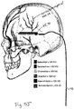
- the supraorbital nerve exits at foramen 1, approximately 3.1-3.8 cm from the nasal midline (in adults), and is located immediately above the orbital ridge that is located below the eyebrow.
- the infraorbital branch or maxillary nerve exits at foramen 2, approximately 2.4-3.0 cm from the nasal midline (in adults) and the mentalis nerve exits at foramen 3, approximately 2.0-2.3 cm from the nasal midline (in adults).
- Other sensory branches including the zygomaticofacial, zygomaticoorbital, zygomaticotemporal, and auriculotemporal, arise from other foramina.
- VPM ventral posterior medial nucleus
- Light touch sensory fibers are large myelinated fibers, which ascend to the ventral posterior lateral (VPL) nucleus of the thalamus, and also project to the cerebral cortex. Afferent sensory fibers project from the trigeminal nuclei to the thalamus and the cerebral cortex.
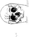
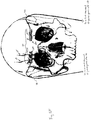
- Fig. 1C illustrates, among other layers, the subcutaneous or connective tissues above the periosteum D or pericranium (a membrane that lines the outer surface of the skull) and below the epidermis A (the outermost layer of skin). Also shown is the frontalis muscle C and the associated aponeurosis. Loose connective tissue separates the aponeurosis and the frontalis muscle from the periosteum.
- the systems and methods disclosed herein may be used in the application of trigeminal nerve stimulation to treat medical disorders including, but not limited to, neuropsychiatric disorders such as depression and major depressive disorder, neurological disorders such as epilepsy and drug resistant epilepsy, cardiac related disorders, fatigue, tinnitus and other medical disorders as may be disclosed in copending application nos. U.S. Patent Application No.: 12/898,685, filed October 5, 2010 and entitled Extracranial Implantable Devices, Systems and Methods for the Treatment of Neuropsychiatric Disorders; U.S.
- Stimulation of peripheral and cutaneous branches of the trigeminal nerve in the face, ear or scalp can be applied and stimulated at safe frequencies, pulse durations and amplitudes.
- Such treatment and prevention is advantageous over the currently used pharmacological approaches which often have undesirable side effects or lack specificity in their actions.
- FIGS. 2-6C show various embodiments of the system and electrode assemblies that may be used for the subcutaneous stimulation of the superficial branches of the trigeminal nerve, spinal nerves and other peripheral nerves and methods of fixation of the same.
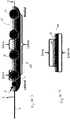
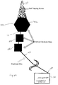
- a system 100 for the subcutaneous stimulation of the superficial branches of the trigeminal nerve which may be implanted in a patient 10 includes an electrode assembly 20, a neurostimulator or pulse generator 30, an electrical cable or lead wire 40 to electrically couple the electrode assembly with the pulse generator, and an anchoring device 70 received in a corresponding aperture 65.
- the pulse generator 30 may be any type of appropriate signal generating device for neurostimulation.
- the pulse generator 30 may include electronic circuitry for receiving data and/or power from outside the body by inductive, radio-frequency (RF), or other electromagnetic coupling.
- electronic circuitry includes an inductive coil for receiving and transmitting RF data and/or power, an integrated circuit (IC) chip for decoding and storing stimulation parameters and generating stimulation pulses, and additional discrete electronic components required to complete the electronic circuit functions, e.g. capacitor(s), resistor(s), transistor(s), coil(s), and the like.
- the pulse generator 30 may include a programmable memory for storing a set(s) of data, stimulation, and control parameters.
- memory may allow stimulation and control parameters to be adjusted to settings that are safe and efficacious with minimal discomfort for each individual.
- Specific parameters may provide therapeutic advantages for various medical disorders. For instance, some patients may respond favorably to intermittent stimulation, while others may require continuous stimulation to treat their symptoms.
- the pulse generator 30 may include a power source and/or power storage device.
- a power source and/or power storage device Possible options for providing power to the system include but are not limited to: an external power source coupled to pulse generator 30, e.g., via an RF link, a self-contained power source utilizing any suitable means of generation or storage of energy (e.g., a primary battery, a replenishable or rechargeable battery such as a lithium ion battery, an electrolytic capacitor, a supercapacitor, a kinetic generator, or the like), and if the self-contained power source is replenishable or rechargeable, means of replenishing or recharging the power source (e.g., an RF link, an optical link, a thermal link, an inductive link, or other energy-coupling link).
- a self-contained power source utilizing any suitable means of generation or storage of energy (e.g., a primary battery, a replenishable or rechargeable battery such as a lithium ion battery, an electrolytic capacitor,
- pulse generator 30 operates independently from other devices. In other embodiments, pulse generator 30 operates in coordination with other implanted device(s) or other device(s) external to the patient's body. For example, a pulse generator may communicate with other implanted neurostimulators, other implanted devices, and/or devices external to a patient's body via, e.g., an RF link, an ultrasonic link, a thermal link, an optical link, or the like. Specifically, pulse generator 30 may communicate with an external remote control (e.g., patient and/or physician programmer) that is capable of sending commands and/or data to a neurostimulator and that may also be capable of receiving commands and/or data from a neurostimulator.
- an external remote control e.g., patient and/or physician programmer
- the system 100 and/or the electrode assembly 20 may be part of a kit.
- the kit may also include instructions for implantation according to a method disclosed herein.
- the kit may also include instructions for monitoring the clinical effects of the stimulation to achieve proper adjustment of stimulation parameters and system configuration.
- the system may utilize a closed loop design and may include a closed loop device or sensing device.
- the closed loop device may include the stimulating electrode or additional set of electrodes, indwelling catheters, or cutaneous or implantable physiologic monitors.
- the device may be configured to detect brain activity, heart rate, pulse oximetry, cerebral blood flow, systolic, diastolic blood pressure, or mean arterial pressure, transcranial Doppler, cardiac parameters (ejection fraction, pulmonary, atrial, or ventricular pressures), heart rate variability (using time, frequency, or non-linear or other measures of heart rate variability), mechanical motion one or more axial directions, the presence of molecules that could signify a potentially-dangerous condition or the achievement of a desired clinical effect, or other physiologic parameters to provide self-tuning adaptive feedback control for the neurostimulator including, but not limited to, fuzzy controllers, LQG (linear-quadratic-gaussian) controllers and artificial neural networks (ANN).
- fuzzy controllers linear-quadratic-gaussian controllers
- ANN artificial neural networks
- Adaptive learning controllers can learn from the previous response of a particular patient or similar patients to stimulation settings which helped alleviate conditions being treated. In some embodiments, this qualitative and/or quantitative feedback may be used by the system to automatically or otherwise adjust the stimulation parameters in a closed-loop fashion to optimize the clinical effects of the stimulation.
- the neurostimulation may be provided using an electrical neurostimulator and the system is configured to deliver a charge density significantly less than 10 ⁇ C/cm 2 at a current density below 25 mA/ cm 2 .
- the output current is 3mA at 250 ⁇ sec, with an electrode radius of 0.2cm and, therefore, the charge density is 0.59 ⁇ C/cm 2 .
- the electrode assembly 20 may be electrically coupled to an external neurostimulator wirelessly, with transfer of energy across the skin by inductive coupling between a coil implanted in the patient and a coil in the external pulse generator. There would of course be no implanted signal generator 30 in such embodiments.
- the electrode assembly 20 may be implanted but the pulse generator is located externally, and the electrical cables 40 electrically couple the implanted electrodes with the external pulse generator.
- the pulse generator itself may be placed in a variety of locations under the skin, such as pectorally, and the leads placed under the skin of the patient to connect the pulse generator and the electrode assembly.
- Fig. 2 illustrates an embodiment of an electrode assembly 20 that may be used in the system 100.
- the electrode assembly 20 may comprise two implanted electrodes 20a and 20b which are placed at, near or adjacent to the supraorbital foramina, located over the orbital ridge approximately 3.1 to 3.8 cm lateral to the nasal midline in adults.
- the electrode assembly is configured for placement at the supraorbital foramen to stimulate both the supraorbital and supratrochlear branches so as to have a pair of contacts positioned approximately where the supraorbital nerve exits the supraorbital foramen above the eye at an average of 32 mm from midline and also a pair of contacts positioned where the supratrochlear nerve exits the foramen at an average of 22 mm from midline.
- the lateral ends 22a and 22b of the electrodes 20a and 20b (respectively) is where each electrode body connects or couples to leads or lead wires 40 for conveying the electrical stimuli from the pulse generator 30.
- the pulse generator 30 itself may be placed in a variety of locations under the skin, such as pectorally, and the leads placed under the skin of the patient to connect to the pulse generator. Alternatively, as discussed above, the pulse generator 30 may be external to the body.
- each electrode body such as electrode body 20a includes at least one contact 60 and at least one aperture 65 configured to accept an anchoring device 70 and insulating areas 75.
- the electrode body 20a may be a paddle or a plate or other appropriate shape.
- Various shapes for the contacts 60 may be implemented.
- contacts 60 may be rectangular as shown, for example, in Figures 3A-1, 3A-2 , or may be disc-shaped as shown in Figs. 3A-3 , 3A-5 , and 3A-7 through 3A-12.
- an electrode may have a thickness of less than 1 mm and include a pair of contacts 60 each comprising a platinum/iridium disk 4mm in diameter with a center-to-center distance of 10mm.
- an electrode may have a thickness of 1 mm and include four contacts 60 each comprising a platinum/iridium disk 2mm in diameter with a lateral center-to-medial center distance of 12mm, a contact-to-contact distance of 2mm.
- the diameter of the disc shaped contact may be less than 2mm, or 3mm, or greater than 4mm. In other embodiments, such as that shown in Figs. 2 and Figs.
- the contacts may be elongated rectangular bodies with rounded corners or other shaped bodies, preferably with rounded corners. Such shapes avoid “hot spots" in the electrical field that may be generated by sharp angular corners.
- the electrode body 20a and 20b and/or the contact points 60 may be made of a noble or refractory metal or compound, such as titanium, titanium nitride, platinum, iridium, tantalum, niobium, rhenium, palladium, gold, nichrome, stainless steel, or alloys of any of these, in order to avoid corrosion or electrolysis which could damage the surrounding tissues and the assembly.
- the body 20a and 20b may have a thickness of 7mm, 5mm, 1mm or less than 1mm.
- the body may have a length Y of 8 cm and width X of 5 mm. In various embodiments, the length Y may be between 1 mm and 10cm and the width X may be between 5 mm and 10 cm.
- the terms "electrode” and “electrode body” are used interchangeably herein.
- the electrode 20a may be a bipolar electrode and include two pairs of contacts including a first pair of conductive contacts 60a and 60b configured for stimulation of a first region, such as the supratrochlear nerve (see Fig. 1A ) and a second pair of conductive contacts 60c and 60d configured for stimulation of a second region, such as the supraorbital nerve (see Fig. 1A ).
- Each pair of contacts is thus configured for an anti-dromic stimulation of the corresponding nerve.
- each pair of contacts is positioned overlaying the same nerve such that the current induced between the contacts travels in the nerve fiber direction.
- the electrode 20a may be a bipolar electrode and include a first contact 60e configured for stimulation of the supratrochlear nerve and the supraorbital nerve in a first region, and a second contact 60f configured for stimulation of the same supraorbital nerve and supraorbital nerve but in a second region.
- a first contact 60e configured for stimulation of the supratrochlear nerve and the supraorbital nerve in a first region
- a second contact 60f configured for stimulation of the same supraorbital nerve and supraorbital nerve but in a second region.
- an electrode assembly 20 may include electrodes 20a and 20b configured for the bilateral simultaneous and asynchronous stimulation of the ophthalmic nerves, its branches and/or other nerves as described herein.
- the electrode assembly 20 may include only an electrode 20a, thereby delivering unilateral stimulation to the ophthalmic nerve, its branches and/or other nerves as described herein. While the electrode assembly 20 is shown in Figs. 2 , 3A-1 and 3A-2 , and others, with pairs of electrical contacts (60a/b, 60c/d, 60e/f), in other embodiments, there may be a greater or lesser number of contacts on each of the bodies 20a, 20b.
- the electrode assembly may include a dual function sensing-stimulating electrode.
- the electrode body 20a and 20b may include a sensing side 21 having sensing contacts 21a and a stimulating side 23 having stimulating contacts 60.
- the sensing side faces the frontal bone portion of the forehead whereas the stimulating side faces the ophthalmic nerves.
- the contacts 21a and 60 may be aligned or directly opposed to each other. In other embodiments, and as can be understood from the partial cross section views of Figs. 3A-14 to 3A-15 , the contacts 21a and 60 maybe at least partially offset from each other.
- the electrode assembly includes one or more electrode bodies configured for sensing and/or stimulation.
- electrode bodies configured for sensing and/or stimulation.
- an electrode body having a sensing side with sensing contacts is placed under the frontalis in the forehead region (see e.g. Fig. 5A ) and/or under the temporalis in the temporal region (see Fig. 5J ). In either location, the electrode body is located in the loose connective tissue between the muscle and the underlying periosteum.
- securing the sensing electrodes to the bone and/or the periosteum underneath the soft tissue facilitates the resolving ability of the sensing electrode to detect seizures and/or other brain activities indicative of neuropsychiatric pathology or normal brain activity. For example, if a patient is known to have seizures originating from the temporal lobes bilaterally (mesial temporal sclerosis) then a sensing array (electrode body/assembly) is placed on the bone over the temporal lobes bilaterally (see e.g. Fig. 5J ). Once seizure activity is detected, the sensing electrode body/assembly will communicate with one or more stimulating electrode assembly and trigger trigeminal nerve stimulation. In embodiments, the sensing side will detect seizure activity and the stimulating side will stimulate the trigeminal nerve (or a respective branch) (e.g. the auriculotemporal nerve shown in Fig. 5J ).
- the electrical contacts 60a, 60c may be flush with the insulating areas 75 of the electrode body 20a.
- the contacts 60a, 60c may be in a raised position relative to the insulating areas 75 of the electrode body 20a.
- the contacts 60a, 60c may be in a recessed position relative to the insulating areas 75 of the body 20a.
- the electrode body comprises an aperture 65 for receiving an anchoring device 70.
- an anchoring device 70 is introduced into the aperture to secure the electrode body at the desired location. By securing the electrode to the bone, lead migration and electrode movement are minimized.
- the anchoring device 70 may be a screw, such as a self tapping screw, a pin, an expandable rivet, a solidifying adhesive material, or other appropriate anchoring device.
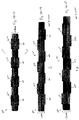
- the aperture 65 and corresponding anchoring device 70 is shown generally at the center of the body 20a and approximately equidistant between the contacts 60, it can be appreciated that the aperture 65 and corresponding anchoring device 70 may be located at an end 22 of the body 20a opposite an end 24 where the lead or lead wire 40 is coupled to the body, such as the embodiments shown in Figs. 3B and 3C . Such end placement may dampen the mechanical motion that is transmitted from the leads to the electrode assembly when the leads are coupled to the body.
- the aperture 65 and corresponding anchoring device 70 may be at another location relative to the electrode body, such as at a location that is not at the midline but rather at a corner or at some location between the midline and the edge or corner.
- the body may include more than one aperture (each of which will receive a respective anchoring device) to further aid in securing the body to the bone.
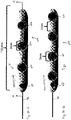
- Figs. 5A-5H illustrate various embodiments of an electrode assembly that may be used with the system 100.
- various lead wire configurations and anchoring point configurations are shown.
- each electrode 20a and 20b has its own corresponding lead 40.
- Each electrode includes two contacts 60 and a centered aperture 65 on its midline and corresponding anchoring device 70.
- Electrode 20a is coupled to a first channel of the pulse generator and electrode 20b is coupled to a second channel of the pulse generator 30, each through an independent lead or cable 40.
- a single lead 40 may drive both electrodes 20a and 20b as shown in Fig. 5B .
- Electrode 20a is coupled to electrode 20b in series via connecting lead 42 and the serially connected electrodes are coupled to a first channel of the pulse generator via lead 40.
- Fig. 5C illustrates a variation of the embodiment of Figure 5B in that the apertures 65 are located at the distal end of each electrode. The same aperture location is shown in Fig. 5D but where each contact 20a and 20b has its own separate lead 40 analogous to the embodiment of Figure 5A .
- each nerve may have its own dedicated pair of contacts 60.
- the four embodiments discussed above with regard to Figures 5A through 5D may be modified such that each contact 20a and 20b includes four contacts 60.
- Figure 5E corresponds to Figure 5B in that a single lead 40 serves both electrodes and each aperture is centrally located on the midline. Electrode 20a is coupled to electrode 20b in series via connecting lead 42 and the serially connected electrodes are coupled to a first channel of the pulse generator 30.
- Fig. 5F corresponds to Figure 5A in that each electrode 20a and 20b has its own dedicated lead 40 and a centered aperture 65 on the midline.
- Electrode 20a is coupled to a first channel of the pulse generator 30 and electrode 20b is coupled to a second channel of the pulse generator 30, each through an independent lead or cable 40.
- Fig. 5G corresponds to Figure 5C in that a single lead 40 serves both electrodes and each aperture is located at the distal end of the electrode on the midline.
- Electrode 20a is coupled to electrode 20b in series via connecting lead 42 and the serially connected electrodes are coupled to a first channel of the pulse generator 30.
- Fig. 5H corresponds to Figure 5D in that each electrode 20a and 20b has its own dedicated lead 40 but the apertures 65 are located at the distal end of their respective electrodes.
- a physician identifies the supraorbital foramen via intra-operative fluoroscopy, and makes a small incision in the eyebrow just lateral to the foramen. Once the incision is made, the surgeon dissects through the soft tissue to the periosteum directly above the foramen and inserts the electrode such that the contacts are facing outwards towards the skin (as opposed to inwards towards the brain) and the electrode body is substantially directly against the bone. More specifically, and with reference to Fig. 1C , an electrode body is positioned in the loose areolar tissue so as to overlay the periosteum D but underlay the frontalis muscle C.
- the contacts face outwards towards the skin.
- the electrode may then be centered about the supraorbital foramen and secured via an anchoring device inserted through the aperture.
- an anchoring device inserted through the aperture.
- the frontalis may be pulled slightly away from the underlying loose areolar tissue such that the supraorbital and supratrochlear nerves will displace with the frontalis muscle. This is quite advantageous as the electrode body may then be inserted into the loose areolar tissue without the danger of transecting or damaging the supraorbital and supratrochlear nerves.
- Locating the electrode in this manner places the contacts in contact with, near, or adjacent to the nerve without requiring direct attachment to the nerve.
- the same implantation procedure can be performed on the contralateral side of the patient as well, for bilateral implantation, or may be performed on one side only for unilateral implantation.
- the electrode assembly Following placement of the electrode assembly, it is then connected to an implanted neurostimulator 30 via the implanted electrical cables 40, which are placed under the patient's skin.
- the stimulation via the neurostimulator 30 is via electrical cables 40.
- the electrical stimulation can be performed wirelessly, with an external, non-implanted neurostimulator, which uses inductive coupling to deliver energy to the implanted electrode assembly 20.
- the electrode assembly 20 is implanted, while the non-implanted neurostimulator is placed externally, and the two are connected via electrical cables 40.
- the electrode assembly 20 may comprise a plurality of multicontact electrodes which may include a plurality of contacts and a plurality of continuous or discrete insulated regions.
- the geometry or layout of the electrode body may be a linear electrode with a single contact or a series or plurality of conductive contacts and insulating spaces, or a flatter, "ribbon” or “strip” electrode, also with the possibility of one or more conductive area(s) and insulated area(s) on the surface(s).
- the electrode assembly 20 is configured to stimulate branches of both the right and left ophthalmic nerves either simultaneously or asynchronously.
- the placement of the first implanted electrode 20a with contact pairs 60 and the second electrode 20b with contact pairs 60 on opposite sides of the nasal midline 12 assures that stimulation current is fiber-directed or in the direction of the afferent ophthalmic or supraorbital nerve.
- this configuration of the electrode assembly 20 allows the electrode contact points 60 to be stimulated independently and/or unilaterally, as the response to stimulus may be localized and thus varied from one side of the midline to the other side.
- the electrical contacts are configured such that current may be stimulated in an orthogonal or perpendicular fashion to the nerve fiber.
- a contact 60 that is lateral to the supraorbital nerve may form one anode/cathode terminal - the use of biphasic pulses makes a contact act as a cathode during one half cycle of the pulse and as an anode during the remaining half cycle of the pulse.
- a contact 60 that is medial to the supratrochlear forms the remaining anode/cathode terminal. In this fashion, current will be excited first in the lateral direction across each nerve fiber and then in the medial direction across each nerve fiber.
- Biphasic pulses have the advantage of no charge build up.
- single phase pulses would involve the use of a dedicated cathode contact and a dedicated anode contact.
- the use of biphasic pulses eliminates the danger of charge buildup.
- one contact 60 should either overlay the nerve fiber or be to one side of the nerve fiber. The remaining contact can then be located to the opposing side of the nerve fiber.
- Figure SI Such an arrangement is shown in Figure SI.
- a pair of contacts is involved in either a fiber-directed or orthogonally-directed embodiment. In a fiber-directed embodiment, both contacts overlay the nerve fiber.
- One contact is distally located on the fiber whereas the other is proximally located.
- one contact 60 is distally positioned away from the foramen whereas another contact 60 is proximally positioned towards the foramen.
- one contact 60 is positioned relatively lateral to the nerve fibers whereas another is positioned relatively medial to the nerve fibers. Should these medial and lateral contacts 60 form the anode/cathode terminals, current will thus alternate in the medial and lateral directions across the nerve. In that regard, it is well known that it is the cathode terminal that excites (depolarizes) a nerve fiber. In contrast, an anode terminal will tend to hyperpolarize the nerve fiber. For this reason, the anode terminal is commonly denoted as the reference of "indifferent" terminal. So if the pulses are not biphasic, a cathode terminal may be positioned to overlay or be adjacent (overlay but be slightly medial or lateral) to a given nerve fiber. The anode terminal location is not so critical.
- a given contact 60 acts as both a cathode and an anode.
- a pair of contacts 60 form cathode/anode terminals. While one contact acts as the anode, the other acts as the cathode, and vice versa.
- contacts may form groups. In other words, one lead 40 couples to a group of contacts 60 whereas another lead 40 couples to another group of contacts 60. While the one group acts as a cathode, the other group acts as an anode, and vice versa.
- each contact 60 should be positioned appropriately in that each contact will be acting as a cathode during half of each biphasic pulse from pulse generator 30.
- each electrode 20a and 20b may be considered to have a proximal side (the side facing towards the supraorbital arch) and a distal side (the side facing towards the hairline).
- one contact 60 is thus located towards the distal side of the electrode body whereas an opposing contact 60 is located towards the proximal side of the electrode.
- the contacts 60 are located with regard to the nerve fiber such that current is directed across the nerve fiber in a lateral direction and then in a medial direction.
- at least one contact 60 is thus located towards the medial end of the electrode body whereas an at least one opposing contact 60 is located towards the lateral end of the electrode body.
- Fig. 2 illustrates an electrode assembly 20 implanted bilaterally and in other embodiments, the electrode assembly may be implanted unilaterally. While Figure 2 illustrates an approach to implantation to stimulate the supraorbital and supratrochlear nerves, a similar process can be used in other subcutaneous locations to stimulate any of the major or minor branches of the trigeminal system.
- an implantable electrode system may be used for spinal nerve stimulation by stimulating a nerve as it exits from the vertebral foramina.
- the anchoring device 70 may be a self-tapping screw, and is coupled to a distal end 40a of an insulated wire 40.
- the proximal end 40b of the wire is coupled to the pulse generator 30.
- the self-tapping screw 70 includes a hexagonal, electrically active head 70a.
- At least two electrodes 20a and 20b are also electrically coupled to the wire 40.
- the electrodes 20a and 20b may be spaced between approximately 2mm to 5mm apart.
- the anchoring device 70 Upon delivery, and as discussed in more detail with respect to Figs. 6B-6C , the anchoring device 70 is secured to the border of a natural bony orifice, for example the foramen ovale, rotundum, maxillary, orbitalis, mandibular, lacerum, spinal foramina, etc.
- the device 70 anchors the electrode(s) such that the electrodes are near or in contact with the nerve, while permitting movement of the skeleton without interfering with the stimulation.
- the electrically active screw head 40a will stimulate the nerve bundle as it exits the vertebral foramina as the trajectory of the nerve exiting the foramina may not follow the wire attached to the screw head.
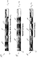
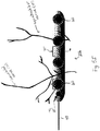
- the electrode assembly 20, anchoring device 70 and lead wire 40 may be delivered via a delivery device 200.
- the delivery device 200 includes a cannula 105 and a stylet 110.
- the delivery device 200 may further include an applicator or driver 115, such as a hollow screw driver or wrench, to aid in implanting the anchoring device 70.
- the stylet is removably received in the cannula, and upon delivery of the cannula to the target location, the stylet is removed and the hollow screw driver 115 (wrench) is introduced to deliver the self-tapping screw 70 directed by the cannula.
- the length of the device 200 will depend on the nerve to be stimulated and the distance between the skin and the target site into which the anchoring device will be delivered.
- the trigeminal nerve is generally close to the skin and runs parallel to the skull surface with the supra-orbital foramen accessible and identifiable under fluoroscopy, the device 200 can be approximately 5-7cm in length (including the handle of the driver).
- a surgeon identifies the target location via intra-operative fluoroscopy, makes a stab-wound incision and percutaneously introduces the device 200 with the stylet 110.
- the device 200 is advanced to the target location under fluoroscopy guidance, and the stylet is removed from the cannula when the cannula is in direct contact with the target bone location.
- the anchoring device 70, electrode assembly 20 and lead wire 40 are held by the hollow screw driver 115 with the proximal end 40b of the wire exiting through the proximal end 115a of the screw driver 115.
- the screw driver 115 advances the assembly and anchoring device through the cannula and aids in securing the anchoring device 70 to the bone at the target location.
- the other contacts 20a and 20b will stay in the soft tissue near the location of the nerve or its branches and will move with the soft tissue as the patient moves.
- the screw driver is removed and the lead wire is tunneled to the location of the pulse generator.
- the anchoring device forms a single anode/cathode contact.
- the stimulation of a nerve of course requires another anode/cathode contact.
- a second anchoring device and corresponding lead may be percutaneously implanted adjacent the first anchoring device.
- the electrode assembly Following placement of the electrode assembly, it is then connected to an implanted neurostimulator 30 via the implanted electrical cables 40, which are placed under the patient's skin.
- the stimulation via the neurostimulator 30 is via electrical cables 40.
- the electrical stimulation can be performed wirelessly, with an external, non-implanted neurostimulator, which uses inductive coupling to deliver energy to the implanted electrode assembly 20.
- the electrode assembly 20 may be implanted, while the neurostimulator is placed external to the body, and the two are connected via electrical cable(s) 40.
- Stimulation may be provided by selecting operational parameters such as the pulse duration, the electrode current, the duty cycle and the stimulation frequency; the parameters are selected to ensure that the total charge, the charge density, and charge per phase are well within accepted safety limits for the scalp or facial tissue, other tissues surrounding nerves and brain.
- the values of the operational parameters are advantageously selected such that a patient will experience a stimulation sensation, such as mild tingling over the forehead and scalp, without causing the patient significant discomfort or pain and with minimal current penetration to the brain. These values may vary according to the treatment of interest, however the parameters are at a charge density significantly less than 10 ⁇ C/cm 2 at a current density below 25 mA/ cm 2 .
- the output current is 3mA at 250 ⁇ sec, with an electrode radius of 0.2cm and, therefore, the charge density is 0.59 ⁇ C/cm 2 .
- selection of the electrical stimulation parameters, electrode design, and inter-electrode distance is made such that the electrical stimulation zone includes the superficial elements of the trigeminal nerves (approximately 3-4 mm deep), while preventing or minimizing current penetration beneath the bone tissue of the skull.
- lower currents e.g. 0.05-5mA
- careful electrode placement may be selected to avoid recruitment of nerves supplying pain sensation to the teeth.
- lower currents e.g. 0.05-5mA
- the stimulation parameters delivered by the implanted pulse generator may be determined (programmed) at the time the device is surgically implanted. In other embodiments, these parameters may be modified, controlled, or otherwise programmed by an external device. This external programming element communicates with the implanted components wirelessly. This may take place, for example, by radiofrequency signals, by inductive coupling, or other means apparent to one skilled in the art.
Landscapes
- Health & Medical Sciences (AREA)
- Life Sciences & Earth Sciences (AREA)
- Animal Behavior & Ethology (AREA)
- Veterinary Medicine (AREA)
- Public Health (AREA)
- Engineering & Computer Science (AREA)
- Biomedical Technology (AREA)
- General Health & Medical Sciences (AREA)
- Nuclear Medicine, Radiotherapy & Molecular Imaging (AREA)
- Heart & Thoracic Surgery (AREA)
- Radiology & Medical Imaging (AREA)
- Cardiology (AREA)
- Neurology (AREA)
- Neurosurgery (AREA)
- Surgery (AREA)
- Orthopedic Medicine & Surgery (AREA)
- Pathology (AREA)
- Medical Informatics (AREA)
- Molecular Biology (AREA)
- Ophthalmology & Optometry (AREA)
- Vascular Medicine (AREA)
- Electrotherapy Devices (AREA)
Applications Claiming Priority (2)
| Application Number | Priority Date | Filing Date | Title |
|---|---|---|---|
| US201261620879P | 2012-04-05 | 2012-04-05 | |
| PCT/US2013/035499 WO2013152316A1 (en) | 2012-04-05 | 2013-04-05 | Subcutaneous electrodes for cranial nerve stimulation |
Publications (3)
| Publication Number | Publication Date |
|---|---|
| EP2833960A1 EP2833960A1 (en) | 2015-02-11 |
| EP2833960A4 EP2833960A4 (en) | 2015-12-09 |
| EP2833960B1 true EP2833960B1 (en) | 2018-03-07 |
Family
ID=49301098
Family Applications (1)
| Application Number | Title | Priority Date | Filing Date |
|---|---|---|---|
| EP13772822.6A Active EP2833960B1 (en) | 2012-04-05 | 2013-04-05 | Subcutaneous electrodes for cranial nerve stimulation |
Country Status (7)
| Country | Link |
|---|---|
| US (1) | US10035013B2 (enExample) |
| EP (1) | EP2833960B1 (enExample) |
| JP (1) | JP2015513980A (enExample) |
| KR (1) | KR20150014445A (enExample) |
| AU (1) | AU2013243309B2 (enExample) |
| CA (1) | CA2869612A1 (enExample) |
| WO (1) | WO2013152316A1 (enExample) |
Families Citing this family (34)
| Publication number | Priority date | Publication date | Assignee | Title |
|---|---|---|---|---|
| EP2485799A4 (en) | 2009-10-05 | 2013-05-15 | Univ California | EXTRACRANIAL IMPLANTABLE DEVICES, SYSTEMS AND METHOD FOR THE TREATMENT OF NEUROLOGICAL ILLNESSES |
| WO2012075192A2 (en) | 2010-11-30 | 2012-06-07 | The Regents Of The University Of California | Pulse generator for cranial nerve stimulation |
| EP2651497B1 (en) | 2010-12-14 | 2019-02-20 | The Regents of The University of California | Extracranial implantable systems for the treatment of medical disorders |
| KR20140037803A (ko) | 2010-12-14 | 2014-03-27 | 더 리젠트스 오브 더 유니이버시티 오브 캘리포니아 | 의료 질환 치료용 장치, 시스템 및 방법 |
| US9731127B2 (en) * | 2013-04-24 | 2017-08-15 | Neurosigma, Inc. | Modulation of autonomic nervous system activity and integrated electrode assemblies for trigeminal neurostimulation |
| US9731122B2 (en) | 2013-04-29 | 2017-08-15 | Rainbow Medical Ltd. | Electroosmotic tissue treatment |
| WO2016093321A1 (ja) * | 2014-12-11 | 2016-06-16 | 株式会社アイカムス・ラボ | 細胞培養方法及び細胞培養装置 |
| KR102427652B1 (ko) | 2015-03-30 | 2022-08-01 | 세팔리 테크놀로지 에스피알엘 | 삼차 신경의 경피 전기 자극을 위한 장치 |
| US9616221B2 (en) | 2015-07-08 | 2017-04-11 | Rainbow Medical Ltd. | Electrical treatment of Alzheimer's disease |
| US10898716B2 (en) | 2015-10-29 | 2021-01-26 | Rainbow Medical Ltd. | Electrical substance clearance from the brain |
| US9724515B2 (en) | 2015-10-29 | 2017-08-08 | Rainbow Medical Ltd. | Electrical substance clearance from the brain for treatment of Alzheimer's disease |
| US10518085B2 (en) | 2015-12-29 | 2019-12-31 | Rainbow Medical Ltd. | Disc therapy |
| US9950156B2 (en) | 2016-09-13 | 2018-04-24 | Rainbow Medical Ltd. | Disc therapy |
| US9770591B2 (en) | 2015-12-29 | 2017-09-26 | Rainbow Medical Ltd. | Disc therapy |
| US11484706B2 (en) | 2015-12-29 | 2022-11-01 | Discure Technologies Ltd | Disc therapy |
| US10569086B2 (en) | 2017-01-11 | 2020-02-25 | Rainbow Medical Ltd. | Electrical microglial cell activation |
| US10758722B2 (en) | 2017-05-03 | 2020-09-01 | Rainbow Medical Ltd. | Electrical treatment of Parkinson's disease |
| DE202018001803U1 (de) | 2017-05-19 | 2018-06-27 | Cefaly Technology Sprl | Externe Trigeminusnervenstimulation für die Akutbehandlung von Migräneattacken |
| US11723579B2 (en) | 2017-09-19 | 2023-08-15 | Neuroenhancement Lab, LLC | Method and apparatus for neuroenhancement |
| US11717686B2 (en) | 2017-12-04 | 2023-08-08 | Neuroenhancement Lab, LLC | Method and apparatus for neuroenhancement to facilitate learning and performance |
| US11478603B2 (en) | 2017-12-31 | 2022-10-25 | Neuroenhancement Lab, LLC | Method and apparatus for neuroenhancement to enhance emotional response |
| US12280219B2 (en) | 2017-12-31 | 2025-04-22 | NeuroLight, Inc. | Method and apparatus for neuroenhancement to enhance emotional response |
| WO2019175879A1 (en) | 2018-03-14 | 2019-09-19 | Rainbow Medical Ltd. | Electrical substance clearance from the brain |
| US11364361B2 (en) | 2018-04-20 | 2022-06-21 | Neuroenhancement Lab, LLC | System and method for inducing sleep by transplanting mental states |
| DE102018110239A1 (de) * | 2018-04-27 | 2019-10-31 | Precisis Ag | Elektrodenpad zur elektrischen Stimulation |
| WO2020056418A1 (en) | 2018-09-14 | 2020-03-19 | Neuroenhancement Lab, LLC | System and method of improving sleep |
| US12357792B2 (en) | 2019-01-04 | 2025-07-15 | Shifamed Holdings, Llc | Internal recharging systems and methods of use |
| US11123197B2 (en) | 2019-09-03 | 2021-09-21 | Rainbow Medical Ltd. | Hydropneumatic artificial intervertebral disc |
| US10881858B1 (en) | 2019-09-18 | 2021-01-05 | Rainbow Medical Ltd. | Electrical substance clearance from the brain |
| EP4138981A4 (en) | 2020-04-23 | 2024-05-22 | Shifamed Holdings, LLC | Power management for interatrial shunts and associated systems and methods |
| US11298530B1 (en) | 2021-05-03 | 2022-04-12 | Discure Technologies Ltd. | Synergistic therapies for intervertebral disc degeneration |
| US11344721B1 (en) | 2021-08-16 | 2022-05-31 | Rainbow Medical Ltd. | Cartilage treatment |
| US11413455B1 (en) | 2022-02-08 | 2022-08-16 | Rainbow Medical Ltd. | Electrical treatment of Alzheimer's disease |
| US12208267B1 (en) | 2024-04-19 | 2025-01-28 | Yossi Gross | Blood flow enhancement therapy system |
Family Cites Families (22)
| Publication number | Priority date | Publication date | Assignee | Title |
|---|---|---|---|---|
| US20010025192A1 (en) * | 1999-04-29 | 2001-09-27 | Medtronic, Inc. | Single and multi-polar implantable lead for sacral nerve electrical stimulation |
| US6952613B2 (en) | 2001-01-31 | 2005-10-04 | Medtronic, Inc. | Implantable gastrointestinal lead with active fixation |
| US6792314B2 (en) * | 2001-06-18 | 2004-09-14 | Alfred E. Mann Foundation For Scientific Research | Miniature implantable array and stimulation system suitable for eyelid stimulation |
| WO2005000090A2 (en) * | 2003-05-30 | 2005-01-06 | Medi-Screw, Inc. | Medical implant systems |
| WO2005062829A2 (en) * | 2003-12-19 | 2005-07-14 | Advanced Bionics Corporation | Skull-mounted electrical stimulation system and method for treating patients |
| US7920915B2 (en) * | 2005-11-16 | 2011-04-05 | Boston Scientific Neuromodulation Corporation | Implantable stimulator |
| US8204607B2 (en) * | 2005-06-09 | 2012-06-19 | Medtronic, Inc. | Implantable medical lead |
| EP1931418B1 (en) * | 2005-10-03 | 2012-11-21 | Washington University | Electrode for stimulating bone growth, tissue healing and/or pain control |
| GB0604613D0 (en) * | 2006-03-07 | 2006-04-19 | Simpson Brian A | Electrostimulation device |
| US9314618B2 (en) * | 2006-12-06 | 2016-04-19 | Spinal Modulation, Inc. | Implantable flexible circuit leads and methods of use |
| US20080140151A1 (en) * | 2006-12-11 | 2008-06-12 | Brodkey Jason A | Nerve stimulation apparatus and method for the treatment of head pain |
| KR101485815B1 (ko) * | 2007-07-04 | 2015-01-23 | 고쿠리츠다이가쿠호진 히로시마다이가쿠 | 경두개 전기 자극 장치 |
| US8214057B2 (en) * | 2007-10-16 | 2012-07-03 | Giancarlo Barolat | Surgically implantable electrodes |
| EP2092951A1 (fr) * | 2008-02-20 | 2009-08-26 | Stx-Med Sprl | Appareil pour le traîtement électrothérapeutique des céphalées de tension |
| CN102202725B (zh) * | 2008-10-21 | 2016-06-01 | Med-El电气医疗器械有限公司 | 用于面神经刺激的系统和方法 |
| US8494641B2 (en) | 2009-04-22 | 2013-07-23 | Autonomic Technologies, Inc. | Implantable neurostimulator with integral hermetic electronic enclosure, circuit substrate, monolithic feed-through, lead assembly and anchoring mechanism |
| EP2485799A4 (en) * | 2009-10-05 | 2013-05-15 | Univ California | EXTRACRANIAL IMPLANTABLE DEVICES, SYSTEMS AND METHOD FOR THE TREATMENT OF NEUROLOGICAL ILLNESSES |
| US9101766B2 (en) * | 2009-10-16 | 2015-08-11 | The Board Of Trustees Of The Leland Stanford Junior University | Eliciting analgesia by transcranial electrical stimulation |
| EP2651497B1 (en) | 2010-12-14 | 2019-02-20 | The Regents of The University of California | Extracranial implantable systems for the treatment of medical disorders |
| US20120203301A1 (en) * | 2011-02-07 | 2012-08-09 | Advanced Neuromodulation Systems, Inc. | Methods using trigeminal nerve stimulation to treat neurological diseases |
| WO2012145244A1 (en) * | 2011-04-20 | 2012-10-26 | Medtronic, Inc. | Method and apparatus for assessing neural activation |
| US10220211B2 (en) * | 2013-01-22 | 2019-03-05 | Livanova Usa, Inc. | Methods and systems to diagnose depression |
-
2013
- 2013-04-05 JP JP2015504752A patent/JP2015513980A/ja not_active Ceased
- 2013-04-05 EP EP13772822.6A patent/EP2833960B1/en active Active
- 2013-04-05 WO PCT/US2013/035499 patent/WO2013152316A1/en not_active Ceased
- 2013-04-05 CA CA2869612A patent/CA2869612A1/en not_active Abandoned
- 2013-04-05 AU AU2013243309A patent/AU2013243309B2/en not_active Ceased
- 2013-04-05 US US14/390,986 patent/US10035013B2/en active Active
- 2013-04-05 KR KR20147031070A patent/KR20150014445A/ko not_active Withdrawn
Non-Patent Citations (1)
| Title |
|---|
| None * |
Also Published As
| Publication number | Publication date |
|---|---|
| CA2869612A1 (en) | 2013-10-10 |
| WO2013152316A1 (en) | 2013-10-10 |
| KR20150014445A (ko) | 2015-02-06 |
| US20150119898A1 (en) | 2015-04-30 |
| AU2013243309A1 (en) | 2014-10-30 |
| US10035013B2 (en) | 2018-07-31 |
| EP2833960A1 (en) | 2015-02-11 |
| AU2013243309B2 (en) | 2017-05-11 |
| EP2833960A4 (en) | 2015-12-09 |
| JP2015513980A (ja) | 2015-05-18 |
Similar Documents
| Publication | Publication Date | Title |
|---|---|---|
| EP2833960B1 (en) | Subcutaneous electrodes for cranial nerve stimulation | |
| US20220331581A1 (en) | Extracranial implantable devices, systems and methods for the treatment of neurological disorders | |
| US10537729B2 (en) | Trigeminal neurostimulation based upon pulse counting and chronobiology | |
| US11420042B2 (en) | Systems and methods for delivering neurostimulation using exogenous electrodes | |
| AU2015264879B2 (en) | Extracranial Implantable Devices, Systems and Methods for the Treatment of Neuropsychiatric Disorders |
Legal Events
| Date | Code | Title | Description |
|---|---|---|---|
| PUAI | Public reference made under article 153(3) epc to a published international application that has entered the european phase |
Free format text: ORIGINAL CODE: 0009012 |
|
| 17P | Request for examination filed |
Effective date: 20141029 |
|
| AK | Designated contracting states |
Kind code of ref document: A1 Designated state(s): AL AT BE BG CH CY CZ DE DK EE ES FI FR GB GR HR HU IE IS IT LI LT LU LV MC MK MT NL NO PL PT RO RS SE SI SK SM TR |
|
| AX | Request for extension of the european patent |
Extension state: BA ME |
|
| DAX | Request for extension of the european patent (deleted) | ||
| RA4 | Supplementary search report drawn up and despatched (corrected) |
Effective date: 20151105 |
|
| RIC1 | Information provided on ipc code assigned before grant |
Ipc: A61N 1/36 20060101ALI20151030BHEP Ipc: A61N 1/05 20060101AFI20151030BHEP |
|
| GRAP | Despatch of communication of intention to grant a patent |
Free format text: ORIGINAL CODE: EPIDOSNIGR1 |
|
| STAA | Information on the status of an ep patent application or granted ep patent |
Free format text: STATUS: GRANT OF PATENT IS INTENDED |
|
| INTG | Intention to grant announced |
Effective date: 20170420 |
|
| RAP1 | Party data changed (applicant data changed or rights of an application transferred) |
Owner name: UNITED STATES GOVERNMENT DEPARTMENT OF VETERANS AF Owner name: THE REGENTS OF THE UNIVERSITY OF CALIFORNIA Owner name: NEUROSIGMA, INC. |
|
| GRAJ | Information related to disapproval of communication of intention to grant by the applicant or resumption of examination proceedings by the epo deleted |
Free format text: ORIGINAL CODE: EPIDOSDIGR1 |
|
| STAA | Information on the status of an ep patent application or granted ep patent |
Free format text: STATUS: REQUEST FOR EXAMINATION WAS MADE |
|
| GRAP | Despatch of communication of intention to grant a patent |
Free format text: ORIGINAL CODE: EPIDOSNIGR1 |
|
| STAA | Information on the status of an ep patent application or granted ep patent |
Free format text: STATUS: GRANT OF PATENT IS INTENDED |
|
| INTC | Intention to grant announced (deleted) | ||
| INTG | Intention to grant announced |
Effective date: 20170928 |
|
| GRAS | Grant fee paid |
Free format text: ORIGINAL CODE: EPIDOSNIGR3 |
|
| GRAA | (expected) grant |
Free format text: ORIGINAL CODE: 0009210 |
|
| STAA | Information on the status of an ep patent application or granted ep patent |
Free format text: STATUS: THE PATENT HAS BEEN GRANTED |
|
| AK | Designated contracting states |
Kind code of ref document: B1 Designated state(s): AL AT BE BG CH CY CZ DE DK EE ES FI FR GB GR HR HU IE IS IT LI LT LU LV MC MK MT NL NO PL PT RO RS SE SI SK SM TR |
|
| REG | Reference to a national code |
Ref country code: GB Ref legal event code: FG4D |
|
| REG | Reference to a national code |
Ref country code: CH Ref legal event code: EP Ref country code: AT Ref legal event code: REF Ref document number: 975906 Country of ref document: AT Kind code of ref document: T Effective date: 20180315 |
|
| REG | Reference to a national code |
Ref country code: IE Ref legal event code: FG4D |
|
| REG | Reference to a national code |
Ref country code: DE Ref legal event code: R096 Ref document number: 602013034089 Country of ref document: DE |
|
| REG | Reference to a national code |
Ref country code: NL Ref legal event code: MP Effective date: 20180307 |
|
| REG | Reference to a national code |
Ref country code: LT Ref legal event code: MG4D |
|
| PG25 | Lapsed in a contracting state [announced via postgrant information from national office to epo] |
Ref country code: ES Free format text: LAPSE BECAUSE OF FAILURE TO SUBMIT A TRANSLATION OF THE DESCRIPTION OR TO PAY THE FEE WITHIN THE PRESCRIBED TIME-LIMIT Effective date: 20180307 Ref country code: CY Free format text: LAPSE BECAUSE OF FAILURE TO SUBMIT A TRANSLATION OF THE DESCRIPTION OR TO PAY THE FEE WITHIN THE PRESCRIBED TIME-LIMIT Effective date: 20180307 Ref country code: LT Free format text: LAPSE BECAUSE OF FAILURE TO SUBMIT A TRANSLATION OF THE DESCRIPTION OR TO PAY THE FEE WITHIN THE PRESCRIBED TIME-LIMIT Effective date: 20180307 Ref country code: FI Free format text: LAPSE BECAUSE OF FAILURE TO SUBMIT A TRANSLATION OF THE DESCRIPTION OR TO PAY THE FEE WITHIN THE PRESCRIBED TIME-LIMIT Effective date: 20180307 Ref country code: NO Free format text: LAPSE BECAUSE OF FAILURE TO SUBMIT A TRANSLATION OF THE DESCRIPTION OR TO PAY THE FEE WITHIN THE PRESCRIBED TIME-LIMIT Effective date: 20180607 Ref country code: HR Free format text: LAPSE BECAUSE OF FAILURE TO SUBMIT A TRANSLATION OF THE DESCRIPTION OR TO PAY THE FEE WITHIN THE PRESCRIBED TIME-LIMIT Effective date: 20180307 |
|
| REG | Reference to a national code |
Ref country code: AT Ref legal event code: MK05 Ref document number: 975906 Country of ref document: AT Kind code of ref document: T Effective date: 20180307 |
|
| PG25 | Lapsed in a contracting state [announced via postgrant information from national office to epo] |
Ref country code: GR Free format text: LAPSE BECAUSE OF FAILURE TO SUBMIT A TRANSLATION OF THE DESCRIPTION OR TO PAY THE FEE WITHIN THE PRESCRIBED TIME-LIMIT Effective date: 20180608 Ref country code: BG Free format text: LAPSE BECAUSE OF FAILURE TO SUBMIT A TRANSLATION OF THE DESCRIPTION OR TO PAY THE FEE WITHIN THE PRESCRIBED TIME-LIMIT Effective date: 20180607 Ref country code: SE Free format text: LAPSE BECAUSE OF FAILURE TO SUBMIT A TRANSLATION OF THE DESCRIPTION OR TO PAY THE FEE WITHIN THE PRESCRIBED TIME-LIMIT Effective date: 20180307 Ref country code: LV Free format text: LAPSE BECAUSE OF FAILURE TO SUBMIT A TRANSLATION OF THE DESCRIPTION OR TO PAY THE FEE WITHIN THE PRESCRIBED TIME-LIMIT Effective date: 20180307 Ref country code: RS Free format text: LAPSE BECAUSE OF FAILURE TO SUBMIT A TRANSLATION OF THE DESCRIPTION OR TO PAY THE FEE WITHIN THE PRESCRIBED TIME-LIMIT Effective date: 20180307 |
|
| PG25 | Lapsed in a contracting state [announced via postgrant information from national office to epo] |
Ref country code: RO Free format text: LAPSE BECAUSE OF FAILURE TO SUBMIT A TRANSLATION OF THE DESCRIPTION OR TO PAY THE FEE WITHIN THE PRESCRIBED TIME-LIMIT Effective date: 20180307 Ref country code: AL Free format text: LAPSE BECAUSE OF FAILURE TO SUBMIT A TRANSLATION OF THE DESCRIPTION OR TO PAY THE FEE WITHIN THE PRESCRIBED TIME-LIMIT Effective date: 20180307 Ref country code: PL Free format text: LAPSE BECAUSE OF FAILURE TO SUBMIT A TRANSLATION OF THE DESCRIPTION OR TO PAY THE FEE WITHIN THE PRESCRIBED TIME-LIMIT Effective date: 20180307 Ref country code: NL Free format text: LAPSE BECAUSE OF FAILURE TO SUBMIT A TRANSLATION OF THE DESCRIPTION OR TO PAY THE FEE WITHIN THE PRESCRIBED TIME-LIMIT Effective date: 20180307 Ref country code: EE Free format text: LAPSE BECAUSE OF FAILURE TO SUBMIT A TRANSLATION OF THE DESCRIPTION OR TO PAY THE FEE WITHIN THE PRESCRIBED TIME-LIMIT Effective date: 20180307 Ref country code: IT Free format text: LAPSE BECAUSE OF FAILURE TO SUBMIT A TRANSLATION OF THE DESCRIPTION OR TO PAY THE FEE WITHIN THE PRESCRIBED TIME-LIMIT Effective date: 20180307 |
|
| PGFP | Annual fee paid to national office [announced via postgrant information from national office to epo] |
Ref country code: GB Payment date: 20180427 Year of fee payment: 6 |
|
| PG25 | Lapsed in a contracting state [announced via postgrant information from national office to epo] |
Ref country code: SM Free format text: LAPSE BECAUSE OF FAILURE TO SUBMIT A TRANSLATION OF THE DESCRIPTION OR TO PAY THE FEE WITHIN THE PRESCRIBED TIME-LIMIT Effective date: 20180307 Ref country code: AT Free format text: LAPSE BECAUSE OF FAILURE TO SUBMIT A TRANSLATION OF THE DESCRIPTION OR TO PAY THE FEE WITHIN THE PRESCRIBED TIME-LIMIT Effective date: 20180307 Ref country code: CZ Free format text: LAPSE BECAUSE OF FAILURE TO SUBMIT A TRANSLATION OF THE DESCRIPTION OR TO PAY THE FEE WITHIN THE PRESCRIBED TIME-LIMIT Effective date: 20180307 Ref country code: SK Free format text: LAPSE BECAUSE OF FAILURE TO SUBMIT A TRANSLATION OF THE DESCRIPTION OR TO PAY THE FEE WITHIN THE PRESCRIBED TIME-LIMIT Effective date: 20180307 |
|
| REG | Reference to a national code |
Ref country code: CH Ref legal event code: PL |
|
| REG | Reference to a national code |
Ref country code: DE Ref legal event code: R097 Ref document number: 602013034089 Country of ref document: DE |
|
| REG | Reference to a national code |
Ref country code: BE Ref legal event code: MM Effective date: 20180430 |
|
| PG25 | Lapsed in a contracting state [announced via postgrant information from national office to epo] |
Ref country code: PT Free format text: LAPSE BECAUSE OF FAILURE TO SUBMIT A TRANSLATION OF THE DESCRIPTION OR TO PAY THE FEE WITHIN THE PRESCRIBED TIME-LIMIT Effective date: 20180709 |
|
| PLBE | No opposition filed within time limit |
Free format text: ORIGINAL CODE: 0009261 |
|
| STAA | Information on the status of an ep patent application or granted ep patent |
Free format text: STATUS: NO OPPOSITION FILED WITHIN TIME LIMIT |
|
| REG | Reference to a national code |
Ref country code: IE Ref legal event code: MM4A |
|
| PG25 | Lapsed in a contracting state [announced via postgrant information from national office to epo] |
Ref country code: DK Free format text: LAPSE BECAUSE OF FAILURE TO SUBMIT A TRANSLATION OF THE DESCRIPTION OR TO PAY THE FEE WITHIN THE PRESCRIBED TIME-LIMIT Effective date: 20180307 Ref country code: MC Free format text: LAPSE BECAUSE OF FAILURE TO SUBMIT A TRANSLATION OF THE DESCRIPTION OR TO PAY THE FEE WITHIN THE PRESCRIBED TIME-LIMIT Effective date: 20180307 Ref country code: LU Free format text: LAPSE BECAUSE OF NON-PAYMENT OF DUE FEES Effective date: 20180405 |
|
| 26N | No opposition filed |
Effective date: 20181210 |
|
| PG25 | Lapsed in a contracting state [announced via postgrant information from national office to epo] |
Ref country code: BE Free format text: LAPSE BECAUSE OF NON-PAYMENT OF DUE FEES Effective date: 20180430 Ref country code: LI Free format text: LAPSE BECAUSE OF NON-PAYMENT OF DUE FEES Effective date: 20180430 Ref country code: CH Free format text: LAPSE BECAUSE OF NON-PAYMENT OF DUE FEES Effective date: 20180430 Ref country code: SI Free format text: LAPSE BECAUSE OF FAILURE TO SUBMIT A TRANSLATION OF THE DESCRIPTION OR TO PAY THE FEE WITHIN THE PRESCRIBED TIME-LIMIT Effective date: 20180307 |
|
| PG25 | Lapsed in a contracting state [announced via postgrant information from national office to epo] |
Ref country code: FR Free format text: LAPSE BECAUSE OF NON-PAYMENT OF DUE FEES Effective date: 20180507 Ref country code: IE Free format text: LAPSE BECAUSE OF NON-PAYMENT OF DUE FEES Effective date: 20180405 |
|
| REG | Reference to a national code |
Ref country code: DE Ref legal event code: R119 Ref document number: 602013034089 Country of ref document: DE |
|
| GBPC | Gb: european patent ceased through non-payment of renewal fee |
Effective date: 20190405 |
|
| REG | Reference to a national code |
Ref country code: DE Ref legal event code: R073 Ref document number: 602013034089 Country of ref document: DE |
|
| PG25 | Lapsed in a contracting state [announced via postgrant information from national office to epo] |
Ref country code: MT Free format text: LAPSE BECAUSE OF NON-PAYMENT OF DUE FEES Effective date: 20180405 Ref country code: DE Free format text: LAPSE BECAUSE OF NON-PAYMENT OF DUE FEES Effective date: 20191101 Ref country code: GB Free format text: LAPSE BECAUSE OF NON-PAYMENT OF DUE FEES Effective date: 20190405 |
|
| REG | Reference to a national code |
Ref country code: DE Ref legal event code: R074 Ref document number: 602013034089 Country of ref document: DE |
|
| PG25 | Lapsed in a contracting state [announced via postgrant information from national office to epo] |
Ref country code: TR Free format text: LAPSE BECAUSE OF FAILURE TO SUBMIT A TRANSLATION OF THE DESCRIPTION OR TO PAY THE FEE WITHIN THE PRESCRIBED TIME-LIMIT Effective date: 20180307 |
|
| PG25 | Lapsed in a contracting state [announced via postgrant information from national office to epo] |
Ref country code: DE Free format text: LAPSE BECAUSE OF NON-PAYMENT OF DUE FEES Effective date: 20191101 |
|
| PGRI | Patent reinstated in contracting state [announced from national office to epo] |
Ref country code: DE Effective date: 20200311 |
|
| PG25 | Lapsed in a contracting state [announced via postgrant information from national office to epo] |
Ref country code: HU Free format text: LAPSE BECAUSE OF FAILURE TO SUBMIT A TRANSLATION OF THE DESCRIPTION OR TO PAY THE FEE WITHIN THE PRESCRIBED TIME-LIMIT; INVALID AB INITIO Effective date: 20130405 |
|
| PG25 | Lapsed in a contracting state [announced via postgrant information from national office to epo] |
Ref country code: MK Free format text: LAPSE BECAUSE OF NON-PAYMENT OF DUE FEES Effective date: 20180307 |
|
| PG25 | Lapsed in a contracting state [announced via postgrant information from national office to epo] |
Ref country code: IS Free format text: LAPSE BECAUSE OF FAILURE TO SUBMIT A TRANSLATION OF THE DESCRIPTION OR TO PAY THE FEE WITHIN THE PRESCRIBED TIME-LIMIT Effective date: 20180707 |
|
| PGFP | Annual fee paid to national office [announced via postgrant information from national office to epo] |
Ref country code: DE Payment date: 20250429 Year of fee payment: 13 |