EP2833574A1 - Verfahren und vorrichtung zur messung von ethernetleistung - Google Patents
Verfahren und vorrichtung zur messung von ethernetleistung Download PDFInfo
- Publication number
- EP2833574A1 EP2833574A1 EP12876428.9A EP12876428A EP2833574A1 EP 2833574 A1 EP2833574 A1 EP 2833574A1 EP 12876428 A EP12876428 A EP 12876428A EP 2833574 A1 EP2833574 A1 EP 2833574A1
- Authority
- EP
- European Patent Office
- Prior art keywords
- statistical information
- network device
- measurement
- peer end
- measurement object
- Prior art date
- Legal status (The legal status is an assumption and is not a legal conclusion. Google has not performed a legal analysis and makes no representation as to the accuracy of the status listed.)
- Withdrawn
Links
Images
Classifications
-
- H—ELECTRICITY
- H04—ELECTRIC COMMUNICATION TECHNIQUE
- H04L—TRANSMISSION OF DIGITAL INFORMATION, e.g. TELEGRAPHIC COMMUNICATION
- H04L43/00—Arrangements for monitoring or testing data switching networks
- H04L43/08—Monitoring or testing based on specific metrics, e.g. QoS, energy consumption or environmental parameters
- H04L43/0805—Monitoring or testing based on specific metrics, e.g. QoS, energy consumption or environmental parameters by checking availability
- H04L43/0811—Monitoring or testing based on specific metrics, e.g. QoS, energy consumption or environmental parameters by checking availability by checking connectivity
-
- H—ELECTRICITY
- H04—ELECTRIC COMMUNICATION TECHNIQUE
- H04L—TRANSMISSION OF DIGITAL INFORMATION, e.g. TELEGRAPHIC COMMUNICATION
- H04L41/00—Arrangements for maintenance, administration or management of data switching networks, e.g. of packet switching networks
- H04L41/02—Standardisation; Integration
- H04L41/0213—Standardised network management protocols, e.g. simple network management protocol [SNMP]
-
- H—ELECTRICITY
- H04—ELECTRIC COMMUNICATION TECHNIQUE
- H04L—TRANSMISSION OF DIGITAL INFORMATION, e.g. TELEGRAPHIC COMMUNICATION
- H04L43/00—Arrangements for monitoring or testing data switching networks
- H04L43/10—Active monitoring, e.g. heartbeat, ping or trace-route
-
- H—ELECTRICITY
- H04—ELECTRIC COMMUNICATION TECHNIQUE
- H04L—TRANSMISSION OF DIGITAL INFORMATION, e.g. TELEGRAPHIC COMMUNICATION
- H04L12/00—Data switching networks
- H04L12/28—Data switching networks characterised by path configuration, e.g. LAN [Local Area Networks] or WAN [Wide Area Networks]
- H04L12/46—Interconnection of networks
- H04L12/4641—Virtual LANs, VLANs, e.g. virtual private networks [VPN]
Definitions
- the present invention relates to measurement technologies and, in particular, to a method and a device for measuring Ethernet performance.
- An operation administration and maintenance (Operation Administration and Maintenance, OAM) model defined in an Ethernet includes maintenance entity group (Maintenance Entity Group, MEG) end point (MEG End Point, MEP). MEP is the end point of MEG and is able to initiate and terminate an OAM protocol frame which is used for measuring Ethernet performance.
- the network performance measurement may include the measurement of network performance such as the frame loss rate, frame delay, frame jitter and throughput.
- a local end network device transmits a loss measurement message (Loss Measurement Message, LMM) frame to a peer end network device, where the LMM frame contains a transmitted service packet statistic value of the local end network device at the time when the local end network device transmits this LMM frame, and the peer end network device returns a loss measurement reply (Loss Measurement Reply, LMR) frame, where the LMR frame contains a received service message statistic value of the peer end network device at the time when the peer end network device receives this LMM frame. Then, the local end network device may measure the frame loss rate according to the statistic value of service messages contained in the received LMR frame.
- LMM loss measurement message
- LMR loss measurement reply
- Embodiments of the present invention provide a method and a device for measuring Ethernet performance, so as to solve the problem of measuring P2MP topology network performance, thereby improving the capability of measuring network performance.
- One aspect a method for measuring Ethernet performance, includes:
- a method for measuring Ethernet performance includes:
- an device for measuring Ethernet performance includes:
- an device for measuring Ethernet performance includes:
- a first OAM protocol frame transmitted by a local end network device to a peer end network device carries a measurement object indicator, so that the peer end network device can obtain peer end measurement statistical information corresponding to the measurement object indicator according to a corresponding relationship between the measurement object indicator and the peer end measurement statistical information. Since different measurement object indicators may correspond to different peer end measurement statistical information, the flow-based measurement can be achieved and, thus, the problem that measurements in the P2MP topology network cannot be implemented in the prior art is solved, thereby improving the capability of measuring network performance.
- the technical solutions of the present invention may be applied in any measurement of Ethernet performance, for example: the measurement of frame loss rate, frame delay, frame jitter or throughput and the like.
- the local end network device or the peer end network device described in the present invention may be an optical network terminal (Optical Network Terminal, ONT), a customer premises equipment (Customer Premises Equipment, CPE), a digital subscriber line access multiplexer (Digital Subscriber Line Access Multiplexer, DSLAM), a router or a switch.
- ONT Optical Network Terminal
- CPE Customer Premises Equipment
- DSLAM Digital Subscriber Line Access Multiplexer
- the local end network device or the peer end network device described in the present invention may also be other network devices.
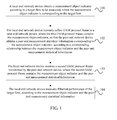
- FIG. 1 is a schematic flowchart of a method for measuring Ethernet performance according to an embodiment of the present invention. As shown in FIG. 1 , the method includes:
- a local end network device obtains a measurement object indicator according to a target flow to be measured, where the measurement object indicator is corresponding to the target flow.
- the target flow may be defined by using a four-tuple composed of fields in Ethernet service packet header, where the four-tuple is ⁇ destination address (Destination Address, DA), source address (Source Address, SA), service priority and virtual local area network (Virtual Local Area Network, VLAN) identifier>; or, the target flow to be measured may be defined by using a subset of the above four-tuple, which will not be limited in this embodiment.
- DA Destination Address
- SA Source Address
- VLAN Virtual Local Area Network
- a target flow of a certain service of the user may be defined by selecting a two-tuple which is ⁇ SA, VLAN ID>, where the VLAN ID refers to the VLAN identifier.
- the local end network device may recognize the target flow to be measured according to an access control list (Access Control List, ACL) determined by a selected tuple.
- ACL is an instruction list of interfaces of a router or a switch, and is used for controlling data packets which flow in or out of the interfaces.
- the ACL includes a control list and a specified action.
- the ACL compares the rules in the control list with the data packets, and performs certain actions for a data packet which is in conformity with the control list, for example, the actions are allowing to pass, forbidding to pass, packet mirroring, traffic statistic and the like.
- the local end network device may specifically obtain the measurement object indicator corresponding to the target flow according to feature information of the target flow to be measured.
- the feature information may include one or multiple of a DA, an SA, a service priority or a VLAN ID.
- the local end network device transmits a first OAM protocol frame to a peer end network device, where the first OAM protocol frame contains the measurement object indicator, so that the peer end network device obtains a peer end measurement statistical information corresponding to the measurement object indicator, according to a corresponding relationship between the measurement object indicator and the peer end measurement statistical information.
- the local end network device receives a second OAM protocol frame transmitted by the peer end network device, where the second OAM protocol frame contains the measurement object indicator and the peer end measurement statistical information.
- the local end network device measures Ethernet performance of the target flow, according to the measurement object indicator and the peer end measurement statistical information.
- the local end network device may also obtain local end measurement statistical information of the target flow; correspondingly, in 102, the first OAM protocol frame, transmitted from the local end network device to the peer end network device, may further contain the local end measurement statistical information. Then, in 103, the second OAM protocol frame received by the local end network device may further contain the local end measurement statistical information. In this case, in 104, the local end network device may specifically measure the Ethernet performance of the target flow according to the measurement object indicator, the local end measurement statistical information and the peer end measurement statistical information.
- the first OAM protocol frame, transmitted from the local end network device to the peer end network device may further contain other fields in the prior art, which will not be repeated herein.
- the measurement object indicator obtained by the local end network device may include but not limit to the fields in the frame header of the first OAM protocol frame or the fields in the frame payload of the first OAM protocol frame.
- the MEP configuration in the prior art may be adopted, namely, the peer end network device contains an MEP, where the MEP may be an extension of the MEP in the prior art, and the number of the object (i.e., the target flow) that each MEP can monitor is extended from one to multiple.
- Each target flow is configured with a group of measurement resource (which may include but not limit to a flow ID (flow ID), a counter and a state machine).
- the MEP monitors each target flow, that is, the MEP matches the service packet through recognizing an ACL of the target flow, makes statistics of the matched service packets by utilizing the configured measurement resource, and generates the peer end measurement statistical information, therefore, the MEP realizes the flow-based monitoring.
- the first OAM protocol frame may use a field contained in the frame payload (i.e., a new field) as the measurement object indicator for indicating the target flow.
- the field contained in the frame payload of the first OAM protocol frame may be the flow ID corresponding to the target flow.
- the OAM control layer entity contained in the peer end network device transmits the first OAM protocol frame to an MEP contained in the peer end network device, and then the MEP contained in the peer end network device may obtain the peer end measurement statistical information corresponding to the flow ID, according to the corresponding relationship between the flow ID and the peer end measurement statistical information.
- the flow ID in the embodiment of the present invention may be in the form of a type length value (Type Length Value, TLV), namely, the flow ID includes: the type of the flow ID, the length of the flow ID and the value of the flow ID.
- TLV Type Length Value
- the local end network device may transmit an LMM frame to the peer end network device, where the LMM frame carries flow ID.
- the flow ID may specifically be represented in the form of TLV.
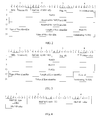
- FIG. 2 Each field in FIG. 2 has the following meaning:
- MEL this field refers to the MEG level, and is used for identifying the MEG level of the LMM frame. The value range is from 0 to 7.
- Operation code (Operation Code, OpCode): this field is used for identifying the type of the LMM frame, and is used for recognizing the content of other parts of the LMM frame. Where, the OpCode of the LMM frame is 43, and the OpCode of the LMR frame is 42.
- TLV offset value this field contains the offset quantity of the first TLV relative to the TLV offset value field. The value of this field is relative to the type of LMM frame. When the TLV offset value is 0, it points to the first byte after the TLV offset value field.
- TxFcf this field is used for recording a transmitted service packet statistic value at the time when the LMM frame is transmitted.
- Reserved for RxFCf in LMR this field is used for recording in the LMR frame, by the peer end network device, a received service message statistic value at the time when the LMM frame is received.
- this field is used for recording in the LMR frame, by the peer end network device, a transmitted service packet statistic value at the time when the LMR frame is transmitted.
- Terminating TLV this field is used for filling, and this field may be a value that all bytes are zero.
- the LMM frame in this embodiment further contains a flow identifier (Flow ID TLV) (namely, a flow ID in the form of TLV), and the Flow ID TLV includes: type of the flow identifier (Flow type), length of the flow identifier (Length) and value of the flow identifier (Flow ID).
- Flow ID TLV flow identifier
- Flow type type of the flow identifier
- Length length of the flow identifier
- Flow ID value of the flow identifier
- the peer end network device may transmit an LMR frame to the local end network device, where the LMR frame carries the flow ID.
- the flow ID may specifically be represented in the form of TLV, please refer to FIG. 3 for the structure of the LMR frame.
- the peer end network device copies the value of TxFCf in the LMM frame into the TxFCf field in the LMR frame, a transmitted statistic value in a peer end measurement statistical information corresponding to the flow identifier is carried in the TxFCb field, and a received statistic value in the peer end measurement statistical information corresponding to the flow identifier is carried in the RxFCf field, where the transmitted statistic value is obtained according to the corresponding relationship between the flow identifier and the peer end measurement statistical information, and the received statistic value is obtained according to the corresponding relationship between the flow identifier and the peer end measurement statistical information.
- the first OAM protocol frame may use a field (i.e., an existing field) contained in the frame header as the measurement object indicator for indicating a target flow.
- a field i.e., an existing field
- the fields contained in the frame header of the first OAM protocol frame may be one or multiple of DA, SA, service priority and VLAN ID.
- the OAM control layer entity contained in the peer end network device transmits the first OAM protocol frame to an MEP contained in the peer end network device, then the MEP contained in the peer end network device may obtain the peer end measurement statistical information corresponding to the two-tuple which is ⁇ SA, service priority>, according to the correspondingly relationship between the two-tuple which is ⁇ SA, service priority> and the peer end measurement statistical information.
- the MEP configuration in the prior art may be extended, that is, the peer end network device may contain two or more MEPs, so that every MEP can still monitor one object (i.e., target flow) according to the solutions in the prior art.
- each MEP is configured with a group of measurement resource (which may include but not limited to an MEP identifier (MEP ID), a counter and a state machine), respectively, and monitors each target flow, that is, the MEPs match the service packet through recognizing an ACL of the target flow, makes statistics of the matched service packets by utilizing the measurement resource respectively allocated for each MEP, and generates the peer end measurement statistical information, therefore, the MEPs realize the flow-based monitoring.
- MEP ID MEP identifier
- counter a state machine
- the first OAM protocol frame may use a field contained in the frame header (i.e., a new field) as the measurement object indicator for indicating the target flow.
- the field contained in the frame header of the first OAM protocol frame may be the MEP ID corresponding to the target flow.
- the OAM control layer entity contained in the peer end network device transmits the first OAM protocol frame to an MEP corresponding to the MEP ID according to the MEP ID, where the MEP is one of multiple MEPs contained in the peer end network device, and then the MEP may obtain the peer end measurement statistical information corresponding to the MEP.
- the local end network device may transmit an LMM frame to the peer end network device, where the LMM frame carries MEP ID.
- the MEP ID may specifically be represented in the form of TLV.
- the structure of the MEP ID TLV i.e., MEP ID in TLV format
- MEP ID TLV includes: type of the MEP (MEP type), length of the MEP ID (Length) and value of the MEP ID (MEP ID).
- MEP type type
- Length length of the MEP ID
- MEP ID value of the MEP ID
- the local end network device may specifically obtain TxFCf field, RxFCf field and TxFCb field from the LMR frame, and temporarily save them together with the current statistic value RxFCl of the local received counter of the local end network device.
- the above testing process is performed once again by using the LMM frame.
- the near-end measurement is to measure the packet loss value associated with packets transmitted by the peer end and received by the local end, i.e., the packet loss value associated with packets transmitted by the peer end network device and received by the local end network device.
- the peer end measurement is to measure the packet loss value associated with packets transmitted by the local end and received by the peer end, i.e., the packet loss value associated with packets transmitted by the local end network device and received by the peer end network device.
- TxFCf [ t c ] is a transmitted service packet statistic value of the local end network at the time when the local end network transmits this LMM frame
- RxFCf [ t c ] is a received service packet statistic value of the peer end network at the time when the peer end network receives this LMM frame
- TxFCf [ t p ] is a transmitted service packet statistic value of the local end network at the time when the local end network transmits a previous LMM frame
- RxFCf [ t p ] is a received service packet statistic value of the peer end network at the time when the peer end network receives this LMM frame;
- TxFCb [ t c ] is a transmitted service packet statistic value of the peer end network at the time when the peer end network transmits this LMM frame
- RxFCl [ t c ] is a received service packet statistic value of the local end network at the time when the local end network receives this LMM frame
- TxFCb[t p ] is a transmitted service packet statistic value of the peer end network at the time when the peer end network transmits a previous LMM frame
- RxFCl[t p ] is a received service packet statistic value of the local end network at the time when the local end network receives a previous LMM frame.
- a first OAM protocol frame transmitted by a local end network device to a peer end network device carries a measurement object indicator, so that the peer end network device can obtain peer end measurement statistical information corresponding to the measurement object indicator according to a corresponding relationship between the measurement object indicator and the peer end measurement statistical information. Since different measurement object indicators may correspond to different peer end measurement statistical information, the flow-based measurement can be achieved and, thus, the problem that measurements in the P2MP topology network cannot be implemented in the prior art is solved, thereby improving the capability of measuring network performance.
- FIG.5 is a schematic flowchart of a method for measuring Ethernet performance according to another embodiment of the present invention, as shown in FIG. 5 , the method includes:
- a peer end network device receives a first OAM protocol frame transmitted by a local end network device, where the first OAM protocol frame contains a measurement object indicator, and the measurement object indicator is obtained by the local end network device according to a target flow to be measured.
- the target flow may be defined by using a four-tuple composed of fields in Ethernet service packet header, where the four-tuple is ⁇ destination address (Destination Address, DA), source address (Source Address, SA), service priority and virtual local area network (Virtual Local Area Network, VLAN) identifier>; or, the target flow to be measured may be defined by using a subset of the above four-tuple, which will not be limited in this embodiment. For example, if multiple services of a certain user use different VLANs, then a target flow of a certain service of the user may be defined by selecting a two-tuple which is ⁇ SA VLAN ID>.
- the local end network device may recognize the target flow to be measured according to an access control list (Access Control List, ACL) determined by a selected tuple.
- ACL is an instruction list of interfaces of a router or a switch, and is used for controlling data packets which flow in or out of the interfaces.
- the ACL includes a control list and specified actions.
- the ACL compares the rules in the control list with the data packets, and performs certain actions for a data packet which is in conformity with the control list, for example, the actions are allowing to pass, forbidding to pass, packet mirroring, traffic statistic and the like.
- the local end network device may specifically obtain the measurement object indicator corresponding to the target flow according to feature information of the target flow to be measured.
- the feature information may include one or multiple of a DA, an SA, a service priority or a VLAN ID.
- the peer end network device obtains peer end measurement statistical information corresponding to the measurement object indicator, according to a corresponding relationship between the measurement object indicator and the peer end measurement statistical information.
- the peer end network device transmits a second OAM protocol frame to the local end network device, where the second OAM protocol frame contains the measurement object indicator and the peer end measurement statistical information, so that the local end network device measures Ethernet performance of the target flow according to the measurement object indicator and the peer end measurement statistical information.
- the local end network device may also obtain local end measurement statistical information of the target flow; correspondingly, in 501, the first OAM protocol frame, received by the peer end network device, may further contain the local end measurement statistical information. Then, in 503, the second OAM protocol frame, transmitted from the peer end network device to the local end network device may further contain the local end measurement statistical information.
- the local end network device may specifically measure the Ethernet performance of the target flow according to the measurement object indicator, the local end measurement statistical information and the peer end measurement statistical information.
- the first OAM protocol frame received by the peer end network device may further contain other fields in prior art, which will be not repeated herein.
- the measurement object indicator, contained in the first OAM protocol frame may include but not limit to the fields in the frame header of the first OAM protocol frame or the fields in the frame payload of the first OAM protocol frame.
- the MEP configuration in the prior art may be adopted, namely, the peer end network device contains an MEP, where the MEP may be an extension of the MEP in the prior art, and the number of the object (i.e., the target flow) that each MEP can monitor is extended from one to multiple.
- Each target flow is configured with a group of measurement resource (which may include but not limit to a flow ID (ID), a counter and a state machine).
- ID flow ID
- the MEP monitors each target flow, that is, the MEP matches the service packet through recognizing an ACL of the target flow, makes statistics of the matched service packets by utilizing the configured measurement resource, and generates the peer end measurement statistical information, therefore, the MEP realizes the flow-based monitoring.
- the first OAM protocol frame may use a field contained in the frame payload (i.e., a new field) as the measurement object indicator for indicating the target flow.
- the field contained in the frame payload of the first OAM protocol frame may be the flow ID corresponding to the target flow.
- the OAM control layer entity contained in the peer end network device transmits the first OAM protocol frame to an MEP contained in the peer end network device, and then the MEP contained in the peer end network device may obtain the peer end measurement statistical information corresponding to the flow ID, according to the corresponding relationship between the flow ID and the peer end measurement statistical information.
- the relative content in the embodiment corresponding to FIG. 1 which will not be repeated herein.
- the first OAM protocol frame may use a field (i.e., an existing field) contained in the frame header as the measurement object indicator for indicating a target flow.
- a field i.e., an existing field
- the fields contained in the frame header of the first OAM protocol frame may be one or multiple of DA, SA, service priority and VLAN ID.
- the MEP contained in the peer end network device may obtain the peer end measurement statistical information corresponding to the two-tuple which is ⁇ SA, service priority>, according to the correspondingly relationship between the two-tuple which is ⁇ SA, service priority> and the peer end measurement statistical information.
- the MEP configuration in the prior art i.e., the peer end network device contains one MEP
- the peer end network device may contain two or more MEPs, so that every MEP can still monitor one object (i.e., target flow) according to the solutions in the prior art.
- each MEP is configured with a group of measurement resource (which may include but not limited to an MEP identifier (MEP ID), a counter and a state machine) respectively, and monitors each target flow, that is, the MEPs match the service packet through recognizing an ACL of the target flow, makes statistics of the matched service packets by utilizing the measurement resource respectively allocated for each MEP, and generates the peer end measurement statistical information, therefore, the MEPs realize the flow-based monitoring.
- MEP ID MEP identifier
- counter a state machine
- the first OAM protocol frame may use a field contained in the frame header (i.e., a new field) as the measurement object indicator for indicating the target flow.
- the field contained in the frame header of the first OAM protocol frame may be the MEP ID corresponding to the target flow.
- the OAM control layer entity contained in the peer end network device transmits the first OAM protocol frame to an MEP corresponding to the MEP ID according to the MEP ID, where the MEP is one of multiple MEPs contained in the peer end network device, and then the MEP may obtain the peer end measurement statistical information corresponding to the MEP.
- the relative content in the embodiment corresponding to FIG. 1 which will not be repeated herein.
- a first OAM protocol frame transmitted by a local end network device to a peer end network device carries a measurement object indicator, so that the peer end network device can obtain peer end measurement statistical information corresponding to the measurement object indicator according to a corresponding relationship between the measurement object indicator and the peer end measurement statistical information. Since different measurement object indicators may correspond to different peer end measurement statistical information, the flow-based measurement can be achieved and, thus, the problem that measurements in the P2MP topology network cannot be implemented in the prior art is solved, thereby improving the capability of measuring network performance.
- each embodiment has its emphasis.
- contents not described in detail in one embodiment please refer to related contents described in other embodiments.
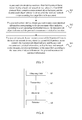
- FIG.6 is a schematic diagram of a device for measuring Ethernet performance according to another embodiment of the present invention, as shown in FIG.6 , the device for measuring Ethernet performance according to this embodiment may include an obtaining unit 61, a transmitter 62, a receiver 63 and a detector 64.
- the obtaining unit 61 is configured to obtain a measurement object indicator according to a target flow to be measured, where the measurement object indicator is corresponding to the target flow;
- the transmitter 62 is configured to transmit a first OAM protocol frame to a peer end network device, where the first OAM protocol frame contains the measurement object indicator, so that the peer end network device obtains a peer end measurement statistical information corresponding to the measurement object indicator, according to a corresponding relationship between the measurement object indicator and the peer end measurement statistical information;
- the receiver 63 is configured to receive a second OAM protocol frame transmitted by the peer end network device, where the second OAM protocol frame contains the measurement object indicator and the peer end measurement statistical information;
- the detector 64 is configured to measure Ethernet performance of the target flow, according to the measurement object indicator and the peer end measurement statistical information.
- the target flow may be defined by using a four-tuple composed of fields in Ethernet service packet header, where the four-tuple is ⁇ destination address (Destination Address, DA), source address (Source Address, SA), service priority and virtual local area network (Virtual Local Area Network, VLAN) identifier>; or, the target flow to be measured may be defined by using a subset of the above four-tuple, which will not be limited in this embodiment. For example, if multiple services of a certain user use different VLANs, then a target flow of a certain service of the user may be defined by selecting a two-tuple which is ⁇ SA, VLAN ID>.
- the device for measuring Ethernet performance may recognize the target flow to be measured according to an access control list (Access Control List, ACL) determined by a selected tuple.
- ACL is an instruction list of interfaces of a router or a switch, and is used for controlling data packets which flow in or out of the interfaces.
- the ACL includes a control list and specified actions.
- the ACL compares the rules in the control list with the data packets, and performs certain actions for a data packet which is in conformity with the control list, for example, the actions are allowing to pass, forbidding to pass, packet mirroring, traffic statistic and the like.
- the obtaining unit 61 may specifically obtain the measurement object indicator corresponding to the target flow according to feature information of the target flow to be measured.
- the feature information may include at least one of a DA, an SA, a service priority or a VLAN ID.
- the obtaining unit 61 may further obtain local end measurement statistical information of the target flow; correspondingly, the first OAM protocol frame, transmitted from the transmitter 62 to the peer end network device, may further contain the local end measurement statistical information. Then, the second OAM protocol frame received by the receiver 63 may further contain the local end measurement statistical information.
- the detector 64 may specifically measure the Ethernet performance of the target flow, according to the measurement object indicator, the local end measurement statistical information and the peer end measurement statistical information.
- the first OAM protocol frame, transmitted from the transmitter 62 to the peer end network device may further include other fields in the prior art, which will not be repeated herein.
- the measurement object indicator obtained by the obtaining unit 61 may include but not limit to the fields in the frame header of the first OAM protocol frame or the fields in the frame payload of the first OAM protocol frame.
- a first OAM protocol frame transmitted by a transmitter to a peer end network device carries a measurement object indicator, so that the peer end network device can obtain peer end measurement statistical information corresponding to the measurement object indicator according to a corresponding relationship between the measurement object indicator and the peer end measurement statistical information. Since different measurement object indicators may correspond to different peer end measurement statistical information, the flow-based measurement can be achieved and, thus, the problem that measurements in the P2MP topology network cannot be implemented in the prior art is solved, thereby improving the capability of measuring network performance.
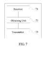
- FIG. 7 is a schematic diagram of a device for measuring Ethernet performance according to another embodiment of the present invention, as shown in FIG.7 , the device for measuring Ethernet performance of this embodiment may include a receiver 71, an obtaining unit 72 and a transmitter 73.
- the receiver 71 is configured to receive a first OAM protocol frame transmitted by a local end network device, where the first OAM protocol frame contains a measurement object indicator, and the measurement object indicator is obtained by the local end network device according to a target flow to be measured
- the obtaining unit 72 is configured to obtain peer end measurement statistical information corresponding to the measurement object indicator, according to a corresponding relationship between the measurement object indicator and the peer end measurement statistical information
- the transmitter 73 is configured to transmit a second OAM protocol frame to the local end network device, where the second OAM protocol frame contains the measurement object indicator and the peer end measurement statistical information, so that the local end network device measures Ethernet performance of the target flow according to the measurement object indicator and the peer end measurement statistical information.
- the target flow may be defined by using a four-tuple composed of fields in Ethernet service packet header, where the four-tuple is ⁇ destination address (Destination Address, DA), source address (Source Address, SA), service priority and virtual local area network (Virtual Local Area Network, VLAN) identifier>; or, the target flow to be measured may be defined by using a subset of the above four-tuple, which will not be limited in this embodiment. For example, if multiple services of a certain user use different VLANs, then a target flow of a certain service of the user may be defined by selecting a two-tuple which is ⁇ SA, VLAN ID>.
- the local end network device may recognize the target flow to be measured according to an access control list (Access Control List, ACL) determined by a selected tuple.
- ACL is an instruction list of interfaces of a router or a switch, and is used for controlling data packets which flow in or out of the interfaces.
- the ACL includes a control list and specified actions.
- the ACL compares the rules in the control list with the data packets, and performs certain actions for a data packet which is in conformity with the control list, for example, the actions are allowing to pass, forbidding to pass, packet mirroring, traffic statistic and the like.
- the local end network device may specifically obtain the measurement object indicator corresponding to the target flow according to feature information of the target flow to be measured.
- the feature information may include at least one of a DA, an SA, a service priority or a VLAN ID.
- the measurement object indicator, contained in the first OAM protocol frame received by the receiver 71 may include but not limit to the fields in the frame header of the first OAM protocol frame or the fields in the frame payload of the first OAM protocol frame.
- the MEP configuration in the prior art may be adopted, namely, the obtaining unit 72 contains an MEP, where the MEP may be an extension of the MEP in the prior art, and the number of the object (i.e., the target flow) that each MEP can monitor is extended from one to multiple.
- Each target flow is configured with a group of measurement resource (which may include but not limit to a flow ID (ID), a counter and a state machine).
- ID flow ID
- the obtaining unit 72 is also configured to monitor each target flow. That is, the MEP matches the service packet through recognizing an ACL of the target flow, makes statistics of the matched service packets by utilizing the configured measurement resource, and generates the peer end measurement statistical information, therefore, the MEP realizes the flow-based monitoring.
- the first OAM protocol frame may use a field contained in the frame payload (i.e., a new field) as the measurement object indicator for indicating the target flow.
- the field contained in the frame payload of the first OAM protocol frame may be the flow identifier corresponding to the target flow; correspondingly, after the receiver 71 receives the first OAM protocol frame, the receiver transmits the first OAM protocol frame to the OAM control layer entity contained in the obtaining unit 72, and the OAM control layer entity contained in the obtaining unit 72 transmits the first OAM protocol frame to an MEP contained in the peer end network device, and then the MEP contained in the obtaining unit 72 may obtain the peer end measurement statistical information corresponding to the flow ID, according to the corresponding relationship between the flow identifier and the peer end measurement statistical information.
- the relative content in the embodiment corresponding to FIG. 1 which will not be repeated herein.
- the first OAM protocol frame may use a field (i.e., an existing field) contained in the frame header as the measurement object indicator for indicating a target flow.
- a field i.e., an existing field
- the fields contained in the frame header of the first OAM protocol frame may be one or multiple of DA, SA, service priority and VLAN ID.
- the receiver 71 may obtain the peer end measurement statistical information corresponding to the two-tuple which is ⁇ SA, service priority>, according to the correspondingly relationship between the two-tuple which is ⁇ SA, service priority> and the peer end measurement statistical information.
- the MEP configuration in the prior art may be extended, that is, the obtaining unit 72 may contain two or more MEPs, so that every MEP can still monitor one object (i.e., target flow) according to the solutions in the prior art.
- each MEP is configured with a group of measurement resource (which may include but not limited to an MEP identifier (MEP ID), a counter and a state machine), respectively.
- the obtaining unit 72 is further configured to monitor each target flow, that is, the MEPs match the service packet through recognizing an ACL of the target flow, makes statistics of the matched service packets by utilizing the measurement resource respectively allocated for each MEP, and generates the peer end measurement statistical information, therefore, the MEPs realize the flow-based monitoring.
- the first OAM protocol frame may use a field contained in the frame header (i.e., a new field) as the measurement object indicator for indicating the target flow.
- the field contained in the frame header of the first OAM protocol frame may be the MEP ID corresponding to the target flow.
- the receiver 71 transmits the first OAM protocol frame to the OAM control layer entity contained in the obtaining unit 72, and the OAM control layer entity contained in the obtaining unit 72 transmits the first OAM protocol frame to an MEP corresponding to the MEP ID according to the MEP ID, where the MEP is one of multiple MEPs contained in the obtaining unit 72, and then the MEP may obtain the peer end measurement statistical information corresponding to the MEP.
- the MEP may obtain the peer end measurement statistical information corresponding to the MEP.
- a first OAM protocol frame transmitted by a local end network device to a peer end network device carries a measurement object indicator, so that the obtaining unit can obtain peer end measurement statistical information corresponding to the measurement object indicator according to a corresponding relationship between the measurement object indicator and the peer end measurement statistical information. Since different measurement object indicators may correspond to different peer end measurement statistical information, the flow-based measurement can be achieved and, thus, the problem that measurements in the P2MP topology network cannot be implemented in the prior art is solved, thereby improving the capability of measuring network performance.
- the disclosed system, device and method may be implemented in other modes.
- the described device embodiments are merely exemplary.
- the unit division is merely logical function division and may be other divisions in actual implementation.
- a plurality of units or components may be combined or integrated into another system, or some features may be ignored or not performed.
- the displayed or discussed mutual couplings or direct couplings or communication connections may be implemented through some interfaces.
- the indirect couplings or communication connections between the apparatuses or units may be implemented in electronic, mechanical or other forms.
- the units described as separate part may or may not be separated physically, and parts displayed as units may or may not be physical units, may be located in one position, or may be distributed on multiple network units. A part or all of the units may be selected according to an actual need to achieve the objectives of the solutions of the embodiments.
- functional units in embodiments of the present invention may be integrated into one processing unit, or each of the units may exist alone physically, or two or more units are integrated into one unit.
- the integrated unit may be implemented through hardware, or may also be implemented in a form of hardware plus a software functional module.
- the detector, the transmitter, the receiver and the obtaining unit may be implemented via a general central processing unit (CPU), an application specific integrated circuit (Application Specific Integrated Circuit, ASIC), or a field programmable gate array (Field Programmable Gate Array, FPGA).
- CPU central processing unit
- ASIC Application Specific Integrated Circuit
- FPGA Field Programmable Gate Array
- the integrated unit implemented in the form of software functional unit may be stored in a computer readable storage medium.
- the software functional unit is stored in a storage medium, and contains several instructions used to instruct computer equipment (for example, a personal computer, a server, or network equipment) to perform the steps of the methods according to the embodiments of the present invention.
- the storage medium may be any medium that can store program codes, such as a U disk, a removable hard disk, a read-only memory (ROM, Read-Only memory), a random access memory (RAM, Random Access Memory), a magnetic disk, or an optical disk.
Landscapes
- Engineering & Computer Science (AREA)
- Computer Networks & Wireless Communication (AREA)
- Signal Processing (AREA)
- Environmental & Geological Engineering (AREA)
- Health & Medical Sciences (AREA)
- Cardiology (AREA)
- General Health & Medical Sciences (AREA)
- Data Exchanges In Wide-Area Networks (AREA)
Applications Claiming Priority (2)
| Application Number | Priority Date | Filing Date | Title |
|---|---|---|---|
| CN2012101419988A CN102651702A (zh) | 2012-05-09 | 2012-05-09 | 以太网性能测量方法及设备 |
| PCT/CN2012/083466 WO2013166811A1 (zh) | 2012-05-09 | 2012-10-25 | 以太网性能测量方法及设备 |
Publications (2)
| Publication Number | Publication Date |
|---|---|
| EP2833574A1 true EP2833574A1 (de) | 2015-02-04 |
| EP2833574A4 EP2833574A4 (de) | 2015-03-25 |
Family
ID=46693598
Family Applications (1)
| Application Number | Title | Priority Date | Filing Date |
|---|---|---|---|
| EP12876428.9A Withdrawn EP2833574A4 (de) | 2012-05-09 | 2012-10-25 | Verfahren und vorrichtung zur messung von ethernetleistung |
Country Status (4)
| Country | Link |
|---|---|
| US (1) | US20150036510A1 (de) |
| EP (1) | EP2833574A4 (de) |
| CN (1) | CN102651702A (de) |
| WO (1) | WO2013166811A1 (de) |
Cited By (1)
| Publication number | Priority date | Publication date | Assignee | Title |
|---|---|---|---|---|
| EP2903214A4 (de) * | 2012-09-29 | 2016-10-26 | Huawei Tech Co Ltd | Messverfahren, vorrichtung und system zur messung eines netzwerkpaketverlusts |
Families Citing this family (8)
| Publication number | Priority date | Publication date | Assignee | Title |
|---|---|---|---|---|
| CN102651702A (zh) * | 2012-05-09 | 2012-08-29 | 华为技术有限公司 | 以太网性能测量方法及设备 |
| WO2014094228A1 (en) * | 2012-12-18 | 2014-06-26 | Telefonaktiebolaget L M Ericsson(Publ) | Method and device for handling dropped data packets |
| CN103227736B (zh) * | 2013-04-08 | 2016-03-09 | 华为技术有限公司 | 一种以太网性能检测方法、系统及光网络终端 |
| CN103401730A (zh) * | 2013-07-31 | 2013-11-20 | 盛科网络(苏州)有限公司 | 链路的通量测量方法及待测设备 |
| CN103401716B (zh) * | 2013-08-06 | 2016-11-23 | 华为技术有限公司 | 网络性能测量的方法、网管设备和网元设备 |
| CN113315645B (zh) * | 2020-02-27 | 2024-06-04 | 华为技术有限公司 | 配置性能探测指示信息的方法及相关设备 |
| CN112911632B (zh) * | 2021-02-04 | 2022-11-29 | 京信网络系统股份有限公司 | 点对多点网络测量方法、装置、通信系统和存储介质 |
| CN114567574B (zh) * | 2022-03-01 | 2023-11-10 | 烽火通信科技股份有限公司 | 一种基于时序控制实现lm免流量测试的方法与装置 |
Citations (2)
| Publication number | Priority date | Publication date | Assignee | Title |
|---|---|---|---|---|
| US6173325B1 (en) * | 1998-07-31 | 2001-01-09 | Microsoft Corporation | Method computer program product, and system for assessing the performance of a packet schedule |
| US20050099955A1 (en) * | 2003-11-10 | 2005-05-12 | Nortel Networks Limited | Ethernet OAM fault isolation |
Family Cites Families (7)
| Publication number | Priority date | Publication date | Assignee | Title |
|---|---|---|---|---|
| CN1992651B (zh) * | 2005-12-29 | 2010-12-01 | 华为技术有限公司 | 检测以太网多播性能的实现方法 |
| CN100550785C (zh) * | 2006-08-30 | 2009-10-14 | 华为技术有限公司 | 一种以太网设备链路故障检测的方法及其系统 |
| US7898965B2 (en) * | 2007-10-12 | 2011-03-01 | Nortel Networks Limited | IP network and performance monitoring using ethernet OAM |
| JP4983930B2 (ja) * | 2008-02-05 | 2012-07-25 | 富士通株式会社 | フレームロス測定方法、システムおよび装置 |
| CN101854268B (zh) * | 2009-04-04 | 2013-06-05 | 华为技术有限公司 | Ip网络性能测量、服务质量控制的方法、装置和系统 |
| CN101729348B (zh) * | 2009-06-01 | 2011-12-28 | 中兴通讯股份有限公司 | 一种点到多点环的保护方法和系统 |
| CN102651702A (zh) * | 2012-05-09 | 2012-08-29 | 华为技术有限公司 | 以太网性能测量方法及设备 |
-
2012
- 2012-05-09 CN CN2012101419988A patent/CN102651702A/zh active Pending
- 2012-10-25 WO PCT/CN2012/083466 patent/WO2013166811A1/zh active Application Filing
- 2012-10-25 EP EP12876428.9A patent/EP2833574A4/de not_active Withdrawn
-
2014
- 2014-10-21 US US14/519,786 patent/US20150036510A1/en not_active Abandoned
Patent Citations (2)
| Publication number | Priority date | Publication date | Assignee | Title |
|---|---|---|---|---|
| US6173325B1 (en) * | 1998-07-31 | 2001-01-09 | Microsoft Corporation | Method computer program product, and system for assessing the performance of a packet schedule |
| US20050099955A1 (en) * | 2003-11-10 | 2005-05-12 | Nortel Networks Limited | Ethernet OAM fault isolation |
Non-Patent Citations (2)
| Title |
|---|
| MR CHAE-SUB LEE: "Performance Measurements and Management for NGN (FGNGN-OD-00239r1)", ITU-T DRAFT ; STUDY PERIOD 2005-2008, INTERNATIONAL TELECOMMUNICATION UNION, GENEVA ; CH, vol. 4/13, 16 January 2006 (2006-01-16), pages 1-83, XP017563447, [retrieved on 2006-05-03] * |
| See also references of WO2013166811A1 * |
Cited By (2)
| Publication number | Priority date | Publication date | Assignee | Title |
|---|---|---|---|---|
| EP2903214A4 (de) * | 2012-09-29 | 2016-10-26 | Huawei Tech Co Ltd | Messverfahren, vorrichtung und system zur messung eines netzwerkpaketverlusts |
| US9985856B2 (en) | 2012-09-29 | 2018-05-29 | Huawei Technologies Co., Ltd. | Method, apparatus and system for measuring network packet loss |
Also Published As
| Publication number | Publication date |
|---|---|
| US20150036510A1 (en) | 2015-02-05 |
| CN102651702A (zh) | 2012-08-29 |
| EP2833574A4 (de) | 2015-03-25 |
| WO2013166811A1 (zh) | 2013-11-14 |
Similar Documents
| Publication | Publication Date | Title |
|---|---|---|
| EP2833574A1 (de) | Verfahren und vorrichtung zur messung von ethernetleistung | |
| EP2884697B1 (de) | Messverfahren, vorrichtung und system zur messung eines netzwerkpaketverlusts | |
| US8520530B2 (en) | Method and apparatus for providing availability metrics for measurement and managment of ethernet services | |
| JP5462954B2 (ja) | パケットロス検出方法及び装置、並びにルータ | |
| EP2242236B1 (de) | Verfahren, system und einrichtung zur messung von rahmenverlusten | |
| CN100463418C (zh) | 网络性能测试方法、系统及网络设备 | |
| US8243608B2 (en) | Metro Ethernet connectivity fault management acceleration | |
| EP2681871B1 (de) | Testen des durchsatzes während des betriebs bei verteilten router/schaltarchitekturen | |
| CN109428782B (zh) | 网络监控的方法和设备 | |
| US9584396B2 (en) | Label-based measurement method, apparatus, and system | |
| WO2012147909A1 (ja) | ネットワーク装置、通信システム、異常トラヒックの検出方法およびプログラム | |
| EP3398296B1 (de) | Leistungsmessung in einem paketvermittelten kommunikationsnetzwerk | |
| EP3474499B1 (de) | Verfahren und vorrichtung zur erkennung der netzwerkleistung | |
| EP3618356B1 (de) | Paketverlustdetektionsvorrichtungen, und -system | |
| US11121938B2 (en) | Performance measurement in a packet-switched communication network | |
| US9331927B2 (en) | Communication system, communication device, and communication method | |
| CN105391592A (zh) | 一种分组传送网业务侦测与测量的方法、装置和系统 | |
| US20180324076A1 (en) | Class of service probe | |
| US9203718B2 (en) | Frame loss measurement device, communication device, communication system and performance measurement method | |
| WO2014000509A1 (zh) | 一种传输监控方法及装置 | |
| CN106571970B (zh) | 承载网的监测方法及装置 | |
| KR20130085488A (ko) | 패킷 전달망의 oam 프레임 처리 장치 및 방법 | |
| KR20100066372A (ko) | 네트워크 통신 시스템에서 신호 처리 장치 및 방법 |
Legal Events
| Date | Code | Title | Description |
|---|---|---|---|
| PUAI | Public reference made under article 153(3) epc to a published international application that has entered the european phase |
Free format text: ORIGINAL CODE: 0009012 |
|
| 17P | Request for examination filed |
Effective date: 20141029 |
|
| AK | Designated contracting states |
Kind code of ref document: A1 Designated state(s): AL AT BE BG CH CY CZ DE DK EE ES FI FR GB GR HR HU IE IS IT LI LT LU LV MC MK MT NL NO PL PT RO RS SE SI SK SM TR |
|
| AX | Request for extension of the european patent |
Extension state: BA ME |
|
| A4 | Supplementary search report drawn up and despatched |
Effective date: 20150219 |
|
| RIC1 | Information provided on ipc code assigned before grant |
Ipc: H04L 12/26 20060101AFI20150213BHEP |
|
| DAX | Request for extension of the european patent (deleted) | ||
| STAA | Information on the status of an ep patent application or granted ep patent |
Free format text: STATUS: THE APPLICATION IS DEEMED TO BE WITHDRAWN |
|
| 18D | Application deemed to be withdrawn |
Effective date: 20150922 |