WO2012147909A1 - ネットワーク装置、通信システム、異常トラヒックの検出方法およびプログラム - Google Patents
ネットワーク装置、通信システム、異常トラヒックの検出方法およびプログラム Download PDFInfo
- Publication number
- WO2012147909A1 WO2012147909A1 PCT/JP2012/061338 JP2012061338W WO2012147909A1 WO 2012147909 A1 WO2012147909 A1 WO 2012147909A1 JP 2012061338 W JP2012061338 W JP 2012061338W WO 2012147909 A1 WO2012147909 A1 WO 2012147909A1
- Authority
- WO
- WIPO (PCT)
- Prior art keywords
- traffic
- network device
- marking
- unit
- processing unit
- Prior art date
Links
Images


Classifications
-
- H—ELECTRICITY
- H04—ELECTRIC COMMUNICATION TECHNIQUE
- H04L—TRANSMISSION OF DIGITAL INFORMATION, e.g. TELEGRAPHIC COMMUNICATION
- H04L47/00—Traffic control in data switching networks
- H04L47/10—Flow control; Congestion control
- H04L47/11—Identifying congestion
- H04L47/115—Identifying congestion using a dedicated packet
-
- H—ELECTRICITY
- H04—ELECTRIC COMMUNICATION TECHNIQUE
- H04L—TRANSMISSION OF DIGITAL INFORMATION, e.g. TELEGRAPHIC COMMUNICATION
- H04L47/00—Traffic control in data switching networks
- H04L47/10—Flow control; Congestion control
- H04L47/11—Identifying congestion
-
- H—ELECTRICITY
- H04—ELECTRIC COMMUNICATION TECHNIQUE
- H04L—TRANSMISSION OF DIGITAL INFORMATION, e.g. TELEGRAPHIC COMMUNICATION
- H04L43/00—Arrangements for monitoring or testing data switching networks
- H04L43/06—Generation of reports
- H04L43/062—Generation of reports related to network traffic
-
- H—ELECTRICITY
- H04—ELECTRIC COMMUNICATION TECHNIQUE
- H04L—TRANSMISSION OF DIGITAL INFORMATION, e.g. TELEGRAPHIC COMMUNICATION
- H04L47/00—Traffic control in data switching networks
- H04L47/10—Flow control; Congestion control
- H04L47/20—Traffic policing
-
- H—ELECTRICITY
- H04—ELECTRIC COMMUNICATION TECHNIQUE
- H04L—TRANSMISSION OF DIGITAL INFORMATION, e.g. TELEGRAPHIC COMMUNICATION
- H04L47/00—Traffic control in data switching networks
- H04L47/10—Flow control; Congestion control
- H04L47/30—Flow control; Congestion control in combination with information about buffer occupancy at either end or at transit nodes
-
- H—ELECTRICITY
- H04—ELECTRIC COMMUNICATION TECHNIQUE
- H04L—TRANSMISSION OF DIGITAL INFORMATION, e.g. TELEGRAPHIC COMMUNICATION
- H04L47/00—Traffic control in data switching networks
- H04L47/10—Flow control; Congestion control
- H04L47/31—Flow control; Congestion control by tagging of packets, e.g. using discard eligibility [DE] bits
-
- H—ELECTRICITY
- H04—ELECTRIC COMMUNICATION TECHNIQUE
- H04L—TRANSMISSION OF DIGITAL INFORMATION, e.g. TELEGRAPHIC COMMUNICATION
- H04L69/00—Network arrangements, protocols or services independent of the application payload and not provided for in the other groups of this subclass
- H04L69/22—Parsing or analysis of headers
Definitions
- the present invention is based on the priority claim of Japanese patent application: Japanese Patent Application No. 2011-099223 (filed on Apr. 27, 2011), the entire contents of which are incorporated herein by reference. Shall.
- the present invention relates to a network device, a communication system, an abnormal traffic detection method, and a program, and more particularly to a network device, a communication system, an abnormal traffic detection method, and a program that can detect abnormal traffic that occurs in a relatively short period of time.
- Patent Documents 1 and 2 have been detected by a search before filing.
- Patent Document 1 discloses a congestion monitoring system that monitors a congestion state related to data transmission between a plurality of devices, and is provided in at least one device, according to a comparison result between a retention amount of unprocessed data and a predetermined threshold.
- Back pressure information generating means for generating back pressure information for instructing the device to stop or continue data transmission, and a device in the preceding stage of the device including the back pressure information generating means, and the contents of the back pressure information
- a data transmission stop unit that stops transmission of data in response, and a monitoring unit that monitors fluctuations in back pressure information sent from the corresponding back pressure information generation unit to the data transmission stop unit in response to the passage of time; Based on information obtained by monitoring by the corresponding monitoring means. Te, and an index calculating means for calculating an index indicating the frequency of occurrence of back pressure, it is that possible congestion monitoring system to determine the indicator of imminent degree for a congestion status in real time.
- Patent Document 2 provides a token counter of an external RAM that holds a token value obtained by adding token values of meter IDs of a plurality of users, extracts meter ID and length information of each packet data, and meter IDs of a predetermined number of packets. And a first information cache and a second information cache for storing packet information including a match flag indicating the mutual identity of the length and a predetermined number of meter IDs. One of the first information cache and the second information cache is provided for the packet information. A first information buffer that is driven to perform an input operation, and the other is switched by a timing generation unit so that token calculation is performed by the token calculation unit for each meter ID, and a flag indicating passage / discard of packet data is set as a calculation result And a second information buffer.
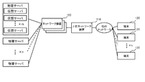
- FIG. 6 is a diagram showing a configuration in which n physical servers are prepared, a virtual server is configured on each physical server, and accessible from k terminals.
- this type of network device 100 has a function of holding the number of discarded packets or the total packet length as a counter value when the upper limit of the interface port bandwidth is reached.
- This counter value is periodically referred to, and if a state in which the traffic amount is higher than a preset level is detected from the difference between the values, this can be detected as congestion. In this case, the monitoring period is generally several seconds to several minutes.
- the above periodic monitoring method targets all traffic and cannot shorten the monitoring cycle from the viewpoint of the load of the monitoring process. For this reason, the amount of traffic within the monitoring period of the above several seconds to several minutes is observed. As a result, the amount of traffic during the period does not reach a predetermined notification level, and as represented by microburst, congestion that occurs in a short period of several ms to several tens of ms can be detected as a congestion state. There is a problem that it is not possible.
- An object of the present invention is to provide a network device, a communication system, a method for detecting abnormal traffic, and a program capable of capturing abnormal traffic to be detected without increasing a load.
- a marking unit that performs marking on traffic that exceeds a predetermined limit rate, a measurement unit that measures the amount of marked traffic, and an assumed duration of abnormal traffic to be detected And a monitoring unit that outputs the measured traffic volume during a period determined according to the network device.
- a first network device including a marking unit that performs marking for traffic exceeding a predetermined limit rate, a measuring unit that measures the marked traffic amount, and detection
- a communication system including a second network device including a monitoring unit that outputs the measured traffic volume in a period determined according to an assumed duration of target abnormal traffic.
- the step of marking traffic that exceeds a predetermined limit rate the step of periodically measuring the marked traffic volume, and the continuation of assumption of abnormal traffic to be detected Outputting the measured traffic volume in a period determined according to time, and providing an abnormal traffic detection method.
- This method is associated with a specific machine such as a network device and a monitoring device for performing the marking and measurement.
- a process for marking traffic that exceeds a predetermined limit rate, a process for periodically measuring the marked traffic volume, and an assumed continuation of abnormal traffic to be detected There is provided a program for causing a computer mounted on a network device to execute a process of outputting the measured traffic volume in a period determined according to time.
- This program can be recorded on a computer-readable storage medium. That is, the present invention can be embodied as a computer program product.
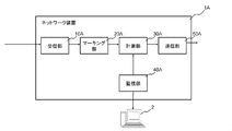
- the marking unit 20A for marking traffic exceeding a predetermined limit rate in addition to the receiving unit 10A and the transmitting unit 50A, the marking unit 20A for marking traffic exceeding a predetermined limit rate, and the marking unit 20A. It can be realized by a network device that includes a measurement unit 30A that periodically measures the traffic volume and a monitoring unit 40A that provides a monitoring function of the measured traffic volume.
- the marking unit 20A performs marking on traffic exceeding a predetermined limit rate, as shown in the shaded area in the left graph of FIG.
- the measurement unit 30A periodically measures the marked traffic volume.
- the monitoring unit 40 ⁇ / b> A outputs to the predetermined monitoring device 2 the amount of traffic in a period determined according to the assumed duration of the abnormal traffic to be detected.
- microburst refers to traffic that occurs and converges in a short period of time that cannot be supplemented with a monitoring period of several seconds to several minutes.
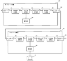
- FIG. 3 is a block diagram illustrating the configuration of the network device according to the first embodiment of this invention.
- a network device including an input port 61, an ingress processing unit 10, a policing processing unit 20, a filter processing unit 30, a monitoring unit 40, an egress processing unit 50, and an output port 62. 1 is shown.
- the input port 61 receives a packet from an external node.
- the “external node” includes a terminal such as a server that transmits a packet, another communication device, and the like.
- the Ingress processing unit 10 performs a predetermined input process on the packet received via the input port 61 and then outputs the packet to the policing processing unit 20.
- the predetermined input process is the same as that performed in an Ingress processing unit installed in a normal network device. For example, when the network device 1 is an Ethernet (registered trademark) switch, packet counting processing associated with MAC address learning, packet transmission, reception, and discarding is performed.
- the policing processing unit 20 performs marking (coloring) processing for each packet input from the Ingress processing unit 10, and then outputs it to the filter processing unit 30.
- the policing processing unit 20 of this embodiment monitors the processing rate of a packet using a leaky bucket algorithm, and performs marking on a packet that has been processed at that timing when a predetermined limit rate is exceeded.
- the predetermined limit rate can be arbitrarily set. For example, when a data rate of 500 Mbps is set as a limit rate on a line of 1 Gbps, marking is performed for a packet exceeding 500 Mbps at the reception timing. .
- this marking process can be realized by setting the CoS (Class of Service) value for specifying the priority in the VLAN tag (IEEE802.1q) to a certain arbitrary value.
- CoS Class of Service
- a VLAN tag (IEEE 802.1q) is set in a packet received from the outside.
- a CoS value representing the priority of a packet in the VLAN tag
- an arbitrary fixed value for example, “0” is set in an external node.
- a process of setting the CoS value to an arbitrary value other than the previous fixed value for example, “1” is performed.
- the filter processing unit 30 counts the total number of packets or the packet length that has been marked by the policing processing unit 20. Further, it is desirable that the filter processing unit 30 performs processing for returning the marked packet after counting. For example, when the above-described marking is performed to change the CoS value from “0” to “1”, a process for returning the CoS value to the original fixed value “0” is performed.
- the filter processing unit 30 transfers the marked packet and the unmarked packet to the Egress processing unit 50.
- the Egress processing unit 50 performs a predetermined output process, and then transmits the received packet from the output port 62.
- the predetermined output processing is equivalent to the content performed in the Egress processing unit installed in a normal network device.
- the network device 1 is an Ethernet (registered trademark) switch
- the MAC address learning table is referred to specify an output port as an output destination, and a packet is output to the output port.
- the monitoring unit 40 reads the value of the counter of the filter processing unit 30 at a period determined so that the microburst can be detected.
- the monitoring unit 40 stores the counter value read last time, and if the difference from the previous value exceeds a predetermined threshold (see the right figure in FIG. 2), the microburst has occurred. As a result, the monitoring device 2 and the operator who are monitoring the entire network including the network device 1 are notified to that effect.
- the predetermined threshold can be arbitrarily set according to the operation target of the network. For example, when the predetermined threshold value is 1, notification is made when the difference from the previous value of the counter of the filter processing unit 30 is 1 or more. In this case, the occurrence of microburst can be strictly detected and notified.
- the predetermined threshold value may be a value other than 1.
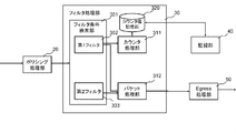
- FIG. 4 is a block diagram illustrating a detailed configuration of the filter processing unit of the network device according to the first embodiment of this invention.
- FIG. 4 there is shown a configuration including a filter condition search unit 301, a counter processing unit 311, a packet processing unit 312 and a counter value storage unit 320.
- the filter condition search unit 301 is set with a first filter 302 in which a condition that matches a marked packet is determined, and a second filter 303 in which a condition that matches all packets including the marked packet is set. ing.
- the filter condition search unit 301 notifies the counter processing unit 311 to increase the counter value stored in the counter value storage unit 320 by a value corresponding to the packet.
- the first filter 302 extracts a packet whose CoS value is the rewritten value (in the above example, “1”). Matching conditions are set.
- a counter having a function of counting the number of packets, a function of accumulating the packet length, or both can be employed.
- the packet processing unit 312 restores the marked portion of the packet matched to the first filter 302 and then outputs it to the Egress processing unit 50. In addition, the packet processing unit 312 outputs a packet matched to the second filter 303 to the Egress processing unit 50 in the same manner.
- each unit (processing means) of the network device 1 shown in FIG. 3 can also be realized by a computer program that causes a computer mounted on the network device 1 to execute the above-described processes using its hardware. .
- marking is performed on a packet that exceeds a predetermined limit rate (see the shaded portion in the left diagram of FIG. 2), and this is processed by the filter processing unit 30.
- a process of counting and visualizing by the monitoring unit 40 is performed (see the right side of FIG. 2).
- the marking (coloring) process for rewriting the CoS value of the VLAN tag has been described.
- other IP header fields may be used.
- the TOS value in the IP header may be used and the filter processing unit may count the packets whose TOS value has been rewritten.
- the TOS value in the IP header is used, the VLAN header is unnecessary.
- the packet processing unit 312 in the filter processing unit 30 has been described as returning the marking (coloring), but a configuration in which the marking (coloring) is not returned may be used. In this case, priority control based on marking (coloring) can be performed outside the egress processing unit 50 or the network device 1.
- the leaky bucket is used as the rate monitoring algorithm in the policing processing unit 20, but other algorithms can also be used.
- FIG. 5 is a block diagram showing the configuration of the network device according to the second embodiment of the present invention. Referring to FIG. 5, a configuration in which a network device 1a and a network device 1b are connected in series is shown.
- the network devices 1a and 1b have substantially the same configuration as that of the network device 1, but are different in that a filter processing unit 30 is provided in front of the policing processing unit 20.
- the filter processing unit 30 of the network device 1a arranged in the preceding stage does not do anything with respect to the packet that has entered from the input port 61, and only performs packet transfer.
- the policing processing unit 20 of the network device 1b arranged in the subsequent stage transfers the packet to the Egress processing unit 50 without performing marking (coloring) processing.
- the egress processing unit 50 of the upstream network device 1a, the output port 62, the input port 61 of the subsequent network device 1b, and the ingress processing unit 10 send packets output from the policing processing unit 20 of the network device 1a to the network device 1b. To the filter processing unit 30.
- the counter value of the filter processing unit 30 is read at a period determined so that the monitoring unit 40 of the network device 1b can detect the microburst. As a result, the occurrence of microburst can be detected by the monitoring device 2 connected to the monitoring unit 40.
- the present invention can be realized using a plurality of network devices. Further, although omitted in the above description, the packets transmitted from the network device 1b to the network device 1a can be monitored in the same processing order.
- FIG. 5 shows a configuration in which two network devices are connected in series in order to help understanding of the present invention.
- the number of network devices 1 may be three or more.
- Other network devices may exist between 1a and 1b.
- the present invention can be realized not only in the configuration of the second embodiment described above but also in a configuration in which the polishing processing unit 20 is disposed after the filter processing unit 30. In this case, the packet counting operation in the filter processing unit 30 of the upstream network device and the marking (coloring) process in the filter processing unit 30 of the downstream network device can be omitted.
- the disclosure of the aforementioned patent document is incorporated herein by reference.
- the embodiments and examples can be changed and adjusted based on the basic technical concept.
- Various combinations or selections of various disclosed elements including each element of each claim, each element of each embodiment, each element of each drawing, etc.) are possible within the scope of the claims and drawings of the present invention. It is. That is, the present invention of course includes various variations and modifications that could be made by those skilled in the art according to the entire disclosure including the claims and the technical idea.
Landscapes
- Engineering & Computer Science (AREA)
- Computer Networks & Wireless Communication (AREA)
- Signal Processing (AREA)
- Computer Security & Cryptography (AREA)
- Data Exchanges In Wide-Area Networks (AREA)
- Mobile Radio Communication Systems (AREA)
- Radio Relay Systems (AREA)
Abstract
Description
本発明は、日本国特許出願:特願2011-099223号(2011年 4月27日出願)の優先権主張に基づくものであり、同出願の全記載内容は引用をもって本書に組み込み記載されているものとする。
本発明は、ネットワーク装置、通信システム、異常トラヒックの検出方法およびプログラムに関し、特に、比較的短い期間において発生する異常トラヒックを検出できるネットワーク装置、通信システム、異常トラヒックの検出方法およびプログラムに関する。
続いて、本発明の第1の実施形態について図面を参照して詳細に説明する。図3は、本発明の第1の実施形態のネットワーク装置の構成を示すブロック図である。図3を参照すると、入力ポート61と、Ingress処理部10と、ポリシング処理部20と、フィルタ処理部30と、監視部40と、Egress処理部50と、出力ポート62と、を備えたネットワーク装置1が示されている。
続いて、複数のネットワーク装置に機能を分散させた本発明の第2の実施形態について図面を参照して詳細に説明する。以下、上記した第1の実施形態との相違点を中心に説明する。
なお、前述の特許文献の開示を、本書に引用をもって繰り込むものとする。
本発明の全開示(請求の範囲および図面を含む)の枠内において、さらにその基本的技術思想に基づいて、実施形態ないし実施例の変更・調整が可能である。また、本発明の請求の範囲および図面の枠内において種々の開示要素(各請求項の各要素、各実施例の各要素、各図面の各要素等を含む)の多様な組み合わせないし選択が可能である。すなわち、本発明は、請求の範囲を含む全開示、技術的思想にしたがって当業者であればなし得るであろう各種変形、修正を含むことは勿論である。
2 監視装置
10 Ingress処理部
10A 受信部
20 ポリシング処理部
20A マーキング部
30 フィルタ処理部
30A 計測部
40、40A 監視部
50 Egress処理部
50A 送信部
61 入力ポート
62 出力ポート
110 上位ネットワーク装置
120 端末
301 フィルタ条件検索部
302 第1フィルタ
303 第2フィルタ
311 カウンタ処理部
312 パケット処理部
320 カウンタ値記憶部
Claims (9)
- 所定の制限レートを超えたトラヒックに対してマーキングを行うマーキング部と、
前記マーキングしたトラヒック量を計測する計測部と、
検出対象の異常トラヒックの想定継続時間に応じて定められた期間における前記計測したトラヒック量を出力する監視部と、
を備えるネットワーク装置。 - 前記計測部は、前記マーキング部によりパケットに書き込まれた情報を検出するフィルタを用いて、トラヒック量を計測する請求項1のネットワーク装置。
- 前記マーキング部は、パケットヘッダの既知の値が設定されている領域の値を書き換えることで、マーキングを行い、
前記計測部は、前記マーキング部により書き換えられた情報を、前記既知の値に復元する処理を行う請求項1または2のネットワーク装置。 - 前記監視部は、任意の時点におけるトラヒック量と、前記任意の時点より前の時点におけるトラヒック量との差が、所定のしきい値を超えていた場合、異常トラヒックが発生したものとして通知を行う請求項1から3いずれか一のネットワーク装置。
- 前記検出対象の異常トラヒックは、マイクロバーストである請求項1から4いずれか一のネットワーク装置。
- 前記マーキング部は、ポリシングを行うポリシング処理部によって構成されている請求項1から5いずれか一のネットワーク装置。
- 所定の制限レートを超えたトラヒックに対してマーキングを行うマーキング部を備えた第1のネットワーク装置と、
前記マーキングしたトラヒック量を計測する計測部と、
検出対象の異常トラヒックの想定継続時間に応じて定められた期間における前記計測したトラヒック量を出力する監視部と、を備える第2のネットワーク装置と、を含む通信システム。 - 所定の制限レートを超えたトラヒックに対してマーキングを行うステップと、
前記マーキングしたトラヒック量を定期的に計測するステップと、
検出対象の異常トラヒックの想定継続時間に応じて定められた期間における前記計測したトラヒック量を出力するステップと、
を含む異常トラヒック検出方法。 - 所定の制限レートを超えたトラヒックに対してマーキングを行う処理と、
前記マーキングしたトラヒック量を定期的に計測する処理と、
検出対象の異常トラヒックの想定継続時間に応じて定められた期間における前記計測したトラヒック量を出力する処理と、
をネットワーク装置に搭載されたコンピュータに実行させるプログラム。
Priority Applications (5)
| Application Number | Priority Date | Filing Date | Title |
|---|---|---|---|
| CN201280020401.2A CN103518354B (zh) | 2011-04-27 | 2012-04-27 | 网络装置、通信系统以及异常通信的检测方法 |
| EP12777668.0A EP2704375B1 (en) | 2011-04-27 | 2012-04-27 | Network device, communication system, method for detecting abnormal traffic, and program |
| US14/114,194 US9306858B2 (en) | 2011-04-27 | 2012-04-27 | Network apparatus, communication system, abnormal traffic detection method, and program |
| JP2013512461A JP5673805B2 (ja) | 2011-04-27 | 2012-04-27 | ネットワーク装置、通信システム、異常トラヒックの検出方法およびプログラム |
| US15/053,674 US9992117B2 (en) | 2011-04-27 | 2016-02-25 | Network apparatus, communication system, abnormal traffic detection method, and program |
Applications Claiming Priority (2)
| Application Number | Priority Date | Filing Date | Title |
|---|---|---|---|
| JP2011099223 | 2011-04-27 | ||
| JP2011-099223 | 2011-04-27 |
Related Child Applications (2)
| Application Number | Title | Priority Date | Filing Date |
|---|---|---|---|
| US14/114,194 A-371-Of-International US9306858B2 (en) | 2011-04-27 | 2012-04-27 | Network apparatus, communication system, abnormal traffic detection method, and program |
| US15/053,674 Continuation US9992117B2 (en) | 2011-04-27 | 2016-02-25 | Network apparatus, communication system, abnormal traffic detection method, and program |
Publications (1)
| Publication Number | Publication Date |
|---|---|
| WO2012147909A1 true WO2012147909A1 (ja) | 2012-11-01 |
Family
ID=47072421
Family Applications (1)
| Application Number | Title | Priority Date | Filing Date |
|---|---|---|---|
| PCT/JP2012/061338 WO2012147909A1 (ja) | 2011-04-27 | 2012-04-27 | ネットワーク装置、通信システム、異常トラヒックの検出方法およびプログラム |
Country Status (5)
| Country | Link |
|---|---|
| US (2) | US9306858B2 (ja) |
| EP (2) | EP3026853A3 (ja) |
| JP (3) | JP5673805B2 (ja) |
| CN (2) | CN103518354B (ja) |
| WO (1) | WO2012147909A1 (ja) |
Cited By (3)
| Publication number | Priority date | Publication date | Assignee | Title |
|---|---|---|---|---|
| JP2013168832A (ja) * | 2012-02-16 | 2013-08-29 | Hitachi Cable Ltd | ネットワーク中継装置 |
| JP2014138405A (ja) * | 2013-01-18 | 2014-07-28 | Kddi Corp | 通信装置 |
| JP5963974B2 (ja) * | 2013-12-11 | 2016-08-03 | 三菱電機株式会社 | 情報処理装置及び情報処理方法及びプログラム |
Families Citing this family (8)
| Publication number | Priority date | Publication date | Assignee | Title |
|---|---|---|---|---|
| JP2015171052A (ja) * | 2014-03-07 | 2015-09-28 | 富士通株式会社 | 識別装置、識別プログラム、及び識別方法 |
| US10341384B2 (en) * | 2015-07-12 | 2019-07-02 | Avago Technologies International Sales Pte. Limited | Network function virtualization security and trust system |
| US20180063007A1 (en) * | 2016-08-31 | 2018-03-01 | Viavi Solutions Inc. | Microburst buffering circuit |
| CN108123843B (zh) * | 2016-11-28 | 2020-04-14 | 中国移动通信有限公司研究院 | 流量检测方法、检测数据处理方法及装置 |
| JP2018157288A (ja) * | 2017-03-16 | 2018-10-04 | 本田技研工業株式会社 | 通信システム |
| WO2020040675A1 (en) * | 2018-08-24 | 2020-02-27 | Telefonaktiebolaget Lm Ericsson (Publ) | Method and communication device for controlling reception of data |
| JP6977699B2 (ja) | 2018-10-30 | 2021-12-08 | 日本電信電話株式会社 | 転送装置及びリソース割当方法 |
| TWI738503B (zh) * | 2020-09-11 | 2021-09-01 | 英業達股份有限公司 | 封包處理系統及其封包處理方法 |
Citations (3)
| Publication number | Priority date | Publication date | Assignee | Title |
|---|---|---|---|---|
| JPH08186572A (ja) * | 1994-12-28 | 1996-07-16 | Nec Corp | セルレート監視装置 |
| JP2005117392A (ja) | 2003-10-08 | 2005-04-28 | Fujitsu Ltd | 輻輳監視システム |
| JP2009206896A (ja) | 2008-02-28 | 2009-09-10 | Fujitsu Ltd | パケット転送装置におけるレート監視方式 |
Family Cites Families (11)
| Publication number | Priority date | Publication date | Assignee | Title |
|---|---|---|---|---|
| JPH08223174A (ja) | 1995-02-16 | 1996-08-30 | Fujitsu Ltd | 輻輳通知制御方法及び輻輳通知制御装置 |
| US6647424B1 (en) * | 1998-05-20 | 2003-11-11 | Nortel Networks Limited | Method and apparatus for discarding data packets |
| US7165117B1 (en) * | 1998-11-12 | 2007-01-16 | Cisco Technology, Inc. | Dynamic IP addressing and quality of service assurance |
| EP1249972A1 (en) | 2001-04-09 | 2002-10-16 | Telefonaktiebolaget L M Ericsson (Publ) | Method of controlling a queue buffer |
| JP2005102104A (ja) | 2003-09-02 | 2005-04-14 | Nippon Telegr & Teleph Corp <Ntt> | Ipマルチキャスト配信システムとそのレート制御方法、およびそのプログラムと記録媒体 |
| US7733779B2 (en) | 2006-06-14 | 2010-06-08 | Cisco Technology, Inc. | Stateless call admission and call preemption with a single metering and marking scheme |
| KR100895282B1 (ko) | 2007-08-08 | 2009-04-29 | 한국전자통신연구원 | 계층적 플로우 동적 관리 방법 및 장치 |
| EP2200230B1 (en) * | 2008-12-16 | 2014-03-12 | Alcatel Lucent | Method and device for performing traffic control in telecommunication networks |
| JP5185862B2 (ja) | 2009-03-11 | 2013-04-17 | 株式会社日立製作所 | トラヒック観測・制御システム |
| EP2237496A1 (en) | 2009-03-31 | 2010-10-06 | BRITISH TELECOMMUNICATIONS public limited company | Pre-congestion notification (PCN) as a base for admission control and flow termination |
| US8649266B2 (en) * | 2009-07-27 | 2014-02-11 | Lester F. Ludwig | Flow state aware management of QoS with a distributed classifier |
-
2012
- 2012-04-27 CN CN201280020401.2A patent/CN103518354B/zh not_active Expired - Fee Related
- 2012-04-27 WO PCT/JP2012/061338 patent/WO2012147909A1/ja active Application Filing
- 2012-04-27 CN CN201610218817.5A patent/CN105897599A/zh active Pending
- 2012-04-27 EP EP15201528.5A patent/EP3026853A3/en not_active Withdrawn
- 2012-04-27 JP JP2013512461A patent/JP5673805B2/ja not_active Expired - Fee Related
- 2012-04-27 EP EP12777668.0A patent/EP2704375B1/en not_active Not-in-force
- 2012-04-27 US US14/114,194 patent/US9306858B2/en active Active
-
2014
- 2014-12-26 JP JP2014264309A patent/JP2015057931A/ja active Pending
- 2014-12-26 JP JP2014264308A patent/JP2015057930A/ja active Pending
-
2016
- 2016-02-25 US US15/053,674 patent/US9992117B2/en active Active
Patent Citations (3)
| Publication number | Priority date | Publication date | Assignee | Title |
|---|---|---|---|---|
| JPH08186572A (ja) * | 1994-12-28 | 1996-07-16 | Nec Corp | セルレート監視装置 |
| JP2005117392A (ja) | 2003-10-08 | 2005-04-28 | Fujitsu Ltd | 輻輳監視システム |
| JP2009206896A (ja) | 2008-02-28 | 2009-09-10 | Fujitsu Ltd | パケット転送装置におけるレート監視方式 |
Non-Patent Citations (2)
| Title |
|---|
| G. KARAGIANNIS: "Requirements for Signaling of (Pre-) Congestion Information in a DiffServ Domain", DRAFT-IETF-PCN-SIGNALING-REQUIREMENTS- 00, 5 July 2010 (2010-07-05), XP055092264 * |
| See also references of EP2704375A4 |
Cited By (3)
| Publication number | Priority date | Publication date | Assignee | Title |
|---|---|---|---|---|
| JP2013168832A (ja) * | 2012-02-16 | 2013-08-29 | Hitachi Cable Ltd | ネットワーク中継装置 |
| JP2014138405A (ja) * | 2013-01-18 | 2014-07-28 | Kddi Corp | 通信装置 |
| JP5963974B2 (ja) * | 2013-12-11 | 2016-08-03 | 三菱電機株式会社 | 情報処理装置及び情報処理方法及びプログラム |
Also Published As
| Publication number | Publication date |
|---|---|
| CN103518354B (zh) | 2016-05-11 |
| CN105897599A (zh) | 2016-08-24 |
| JPWO2012147909A1 (ja) | 2014-07-28 |
| EP2704375B1 (en) | 2016-03-16 |
| US9306858B2 (en) | 2016-04-05 |
| US20160255003A1 (en) | 2016-09-01 |
| EP2704375A1 (en) | 2014-03-05 |
| EP3026853A2 (en) | 2016-06-01 |
| JP2015057930A (ja) | 2015-03-26 |
| JP5673805B2 (ja) | 2015-02-18 |
| JP2015057931A (ja) | 2015-03-26 |
| US9992117B2 (en) | 2018-06-05 |
| CN103518354A (zh) | 2014-01-15 |
| US20140043965A1 (en) | 2014-02-13 |
| EP2704375A4 (en) | 2014-12-17 |
| EP3026853A3 (en) | 2016-10-19 |
Similar Documents
| Publication | Publication Date | Title |
|---|---|---|
| JP5673805B2 (ja) | ネットワーク装置、通信システム、異常トラヒックの検出方法およびプログラム | |
| US10021007B2 (en) | Measuring latency within a networking device | |
| US10305928B2 (en) | Detection of malware and malicious applications | |
| US9819590B2 (en) | Method and apparatus for notifying network abnormality | |
| US20190312816A1 (en) | Flow Control Method and Switching Device | |
| US10069704B2 (en) | Apparatus, system, and method for enhanced monitoring and searching of devices distributed over a network | |
| WO2018102257A1 (en) | Apparatus and system for optimizing communication networks | |
| US20150036510A1 (en) | Method and device for measuring ethernet performance | |
| CN107547430A (zh) | 一种报文发送方法及装置 | |
| US9331927B2 (en) | Communication system, communication device, and communication method | |
| US20140173102A1 (en) | Apparatus, System, and Method for Enhanced Reporting and Processing of Network Data | |
| DK2929472T3 (en) | Device, system and approach for improved network monitoring, data reporting and data processing | |
| CN105704057B (zh) | 确定突发端口拥塞丢包的业务类型的方法和装置 | |
| EP3092737B1 (en) | Systems for enhanced monitoring, searching, and visualization of network data | |
| US20140172852A1 (en) | Apparatus, System, and Method for Reducing Data to Facilitate Identification and Presentation of Data Variations | |
| EP3092771A1 (en) | Apparatus, system, and method for enhanced monitoring and interception of network data | |
| JP5537692B1 (ja) | 品質劣化原因推定装置、品質劣化原因推定方法、品質劣化原因推定プログラム | |
| WO2022199316A1 (zh) | 控制方法、装置及计算设备 |
Legal Events
| Date | Code | Title | Description |
|---|---|---|---|
| WWE | Wipo information: entry into national phase |
Ref document number: 201280020401.2 Country of ref document: CN |
|
| 121 | Ep: the epo has been informed by wipo that ep was designated in this application |
Ref document number: 12777668 Country of ref document: EP Kind code of ref document: A1 |
|
| ENP | Entry into the national phase |
Ref document number: 2013512461 Country of ref document: JP Kind code of ref document: A |
|
| WWE | Wipo information: entry into national phase |
Ref document number: 14114194 Country of ref document: US |
|
| NENP | Non-entry into the national phase |
Ref country code: DE |
|
| WWE | Wipo information: entry into national phase |
Ref document number: 2012777668 Country of ref document: EP |