EP2833018B1 - Fliehkraftpendel und Antriebssystem mit Fliehkraftpendel - Google Patents
Fliehkraftpendel und Antriebssystem mit Fliehkraftpendel Download PDFInfo
- Publication number
- EP2833018B1 EP2833018B1 EP14178302.7A EP14178302A EP2833018B1 EP 2833018 B1 EP2833018 B1 EP 2833018B1 EP 14178302 A EP14178302 A EP 14178302A EP 2833018 B1 EP2833018 B1 EP 2833018B1
- Authority
- EP
- European Patent Office
- Prior art keywords
- pendulum
- mass
- pendulum mass
- combustion engine
- internal combustion
- Prior art date
- Legal status (The legal status is an assumption and is not a legal conclusion. Google has not performed a legal analysis and makes no representation as to the accuracy of the status listed.)
- Active
Links
Images


Classifications
-
- F—MECHANICAL ENGINEERING; LIGHTING; HEATING; WEAPONS; BLASTING
- F16—ENGINEERING ELEMENTS AND UNITS; GENERAL MEASURES FOR PRODUCING AND MAINTAINING EFFECTIVE FUNCTIONING OF MACHINES OR INSTALLATIONS; THERMAL INSULATION IN GENERAL
- F16F—SPRINGS; SHOCK-ABSORBERS; MEANS FOR DAMPING VIBRATION
- F16F15/00—Suppression of vibrations in systems; Means or arrangements for avoiding or reducing out-of-balance forces, e.g. due to motion
- F16F15/10—Suppression of vibrations in rotating systems by making use of members moving with the system
- F16F15/14—Suppression of vibrations in rotating systems by making use of members moving with the system using masses freely rotating with the system, i.e. uninvolved in transmitting driveline torque, e.g. rotative dynamic dampers
- F16F15/1407—Suppression of vibrations in rotating systems by making use of members moving with the system using masses freely rotating with the system, i.e. uninvolved in transmitting driveline torque, e.g. rotative dynamic dampers the rotation being limited with respect to the driving means
- F16F15/145—Masses mounted with play with respect to driving means thus enabling free movement over a limited range
Definitions
- the invention relates to a centrifugal pendulum and a drive system with such a centrifugal pendulum, wherein the centrifugal pendulum comprises a first pendulum mass, a second pendulum mass and a pendulum, said pendulum is coupled to the internal combustion engine, wherein the first pendulum mass and the second pendulum mass on the pendulum to perform a predefined pendulum motion are movably coupled to the pendulum flange.
- the centrifugal pendulum pendulum comprises a pendulum on which pendulum masses are arranged on both sides on different sides of the flange, which are connected to one another via a bolt.
- the centrifugal pendulum is a vibration system that is tuned to a predetermined excitation order. The eradication of torsional vibrations is particularly strong in the field of excitation order and decreases in the direction of higher and lower frequencies of the torsional vibrations.
- an improved centrifugal pendulum for damping a torsional vibration of an internal combustion engine can be provided in that the centrifugal pendulum comprises a first pendulum mass, a second pendulum mass and a pendulum flange.
- the pendulum flange can be coupled with the combustion engine.
- the first pendulum mass and the second pendulum mass are coupled to perform a predefined pendulum motion movable with the pendulum.
- the first pendulum mass is formed differently from the second pendulum mass.
- the first pendulum mass is formed, to attenuate a first exciting order of the internal combustion engine which can be introduced into the pendulum flange.
- the second pendulum mass is designed to dampen a second exciter of the internal combustion engine which can be introduced into the pendulum flange.
- the two exciter orders are different.
- multiple excitation orders can be damped by the centrifugal pendulum in torsional or torsional vibrations, so that in a drive train with an internal combustion engine and such a centrifugal pendulum, the torque prevailing in the drive train is particularly low in vibration.
- a particularly quiet drive system can be provided with a high level of ride comfort.
- a first guide means is provided, which is connected to the first pendulum mass.
- the first guide means is adapted to guide the first pendulum mass in a pendulum motion and to limit a pendulum range of the first pendulum mass.
- a second guide means is provided, which is connected to the second pendulum mass.
- the second guide means is adapted to guide the second pendulum mass in the pendulum motion and to limit a pendulum range of the second pendulum mass.
- the pendulum range of the first pendulum mass overlaps with the pendulum range of the second pendulum mass.
- the pendulum range of the first pendulum mass preferably in the circumferential direction, spaced from the pendulum range of the second pendulum mass may be arranged. In this way, a collision of the two pendulum masses is avoided, so that the centrifugal pendulum is particularly quiet in operation.
- the first pendulum mass has a recess, wherein the recess is arranged on a side of the first pendulum mass assigned to the second pendulum mass.
- the recess is designed to at least partially receive the second pendulum mass.
- the first pendulum mass has a first circumferential extension.
- the second pendulum mass has a second circumferential extent.
- the first extension of the first pendulum mass is different from the second extension of the second pendulum mass.
- a ratio of the mass of the first pendulum mass to the mass of the second pendulum mass is greater than 1. It is particularly advantageous if the ratio is 1.2 to 3, in particular 1.5 to 2.5, particularly advantageously 1.7 to 2.3, or particularly advantageously 2. Due to the ratio of the masses, the centrifugal pendulum can be tuned efficiently to the cylinder deactivation and thus efficiently dampen the torque oscillation of the internal combustion engine both in normal operation and with cylinder deactivation. The ratio is based on the total number of cylinders of the internal combustion engines to the total number of cylinders minus the disabled cylinders.
- an extension of the first pendulum mass in the circumferential direction and / or in the axial direction is different from an extent of the second pendulum mass in the circumferential direction and / or in the axial direction. In this way, the masses of the two pendulum masses can be varied to tune the centrifugal pendulum to different Tilger glovesen.
- the ratio of the extent of the first pendulum mass in the circumferential direction and / or in the axial direction to the extent of the second pendulum mass in the circumferential direction and / or in the axial direction is greater than one.
- the ratio is from 1.2 to 3, in particular preferably 1.5 to 2.5, particularly advantageously 1.7 to 2.3, in particular particularly preferably 2.
- the object of the invention is also achieved by a drive system according to claim 9.
- an improved drive system for a motor vehicle can be provided by the motor vehicle comprising an internal combustion engine and a centrifugal pendulum.
- the combustion engine is coupled to the centrifugal pendulum.
- the internal combustion engine has a first cylinder and at least one second cylinder.
- the internal combustion engine comprises a first operating state, in which the first cylinder and the second cylinder are fuel-fillable. In a second operating state, at least one of the two cylinders is switched off.
- the internal combustion engine has a first exciter order in the first operating state. In the second operating state, the internal combustion engine has a second excitation order. The first exciter order is different to the second exciter order.
- centrifugal pendulum is designed as explained above.
- the first pendulum mass is tuned to the first exciter order of the internal combustion engine and designed to damp the first excitation order.
- the second pendulum mass of the centrifugal pendulum is tuned to the second excitation order of the internal combustion engine and designed to damp the second excitation order of the internal combustion engine.
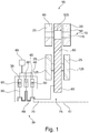
- FIG. 1 shows a longitudinal section through a drive system 15 with a centrifugal pendulum 10 according to a first embodiment.
- FIG. 2 shows a plan view of the in FIG. 1 shown centrifugal pendulum 10.
- FIG. 3 shows a plan view of several pendulum masses 20, 25 of the centrifugal pendulum shown in Figure 1.
- FIG. 4 shows a sectional view along an in FIG. 3 Section A - A shown below FIGS. 1 to 4 be explained together for a better understanding.
- the drive system 15 comprises, in addition to the centrifugal pendulum 10, an internal combustion engine 30.
- the internal combustion engine 30 has a first cylinder 35 and further cylinders 40.
- the cylinders 35, 40 are connected to a fuel supply system 45 of the internal combustion engine 30.
- the fuel supply system 45 is configured to inject fuel into the individual Cylinders 35, 40 to promote.
- a piston 50 is provided in each case, wherein the piston 50 are connected via connecting rods 55 with a crankshaft 60.
- the crankshaft 60 is rotatable about an axis of rotation 61.
- a control system 65 is provided that is configured to control a combustion process in the cylinders 35, 40 of the internal combustion engine 30 to provide torque via the crankshaft 60 to an output shaft 70 of the internal combustion engine 30 ,
- the control system 65 is designed to operate the internal combustion engine 30 in at least two operating states. In this case, all or only part of the pistons 50 can be set in motion in accordance with known operating methods for internal combustion engines 30. In a first operating state, all the cylinders 35, 40 are supplied with fuel, so that the combustion of the fuel in all cylinders takes place simultaneously or offset from one another.
- the control device 65 switches off one of the cylinders 35, 40 so that only two of the three cylinders 35, 40 are supplied with fuel via the fuel supply system 45 and combustion only occurs in these cylinders 35, 40 the operation of the internal combustion engine 30 takes place.
- a single-cylinder cut-off is performed by the controller 65.
- the internal combustion engine 30 a different than in FIG. 2 shown number of cylinders 35, 40 has.
- the internal combustion engine 30 comprises a plurality of cylinder banks, wherein the control device 65 completely shuts off at least one of the plurality of cylinder banks.
- the deactivated cylinder bank or the deactivated individual cylinder 35, 40 is completely decoupled from the remaining other still operated cylinders to avoid running along the cylinder 35 and a cylinder bank. Thereby, a particularly fuel-lean combustion engine can be provided.
- the internal combustion engine 30 In the first operating state, the internal combustion engine 30 has a first excitation order. In the second operating state, the internal combustion engine 30 has a second exciter order deviating from the first exciter system. It should be noted that instead of the excitation order, the internal combustion engine 30 can also have a plurality of excitation orders or a spectrum of exciter orders.
- the internal combustion engine 30 is connected to an input side 75 via an output shaft 70.
- the internal combustion engine 30 provides a torque at the output shaft 70 which, depending on the operating state of the internal combustion engine 30, has a first exciter order or a second exciter order.
- centrifugal pendulum 10 is connected via a torsional vibration damper or a friction clutch with the internal combustion engine 30.
- the centrifugal pendulum 10 has a pendulum flange 80.
- the pendulum flange 80 is formed in the embodiment substantially disc-shaped.
- the input side 75 has a radially inwardly disposed hub 85 which provides a torque-fixed connection to the output shaft 70 of the internal combustion engine 30.
- the centrifugal pendulum 10 has a first pendulum mass 20 and a second pendulum mass 25.
- the first pendulum mass 20 comprises two pendulum mass parts 90 arranged laterally of the pendulum flange 80.
- the first pendulum mass parts 90 are connected by spacers 95.
- the pendulum flange 80 extends between the two pendulum mass parts 90.
- the pendulum flange 80 has a first cutout 100 and a second cutout 105. Through the first cutout 100, the distance bolts 95 are guided.
- a first guide means 106 is provided for the first pendulum mass 20.
- the first guide means 106 comprises the second cutout 105 with a first guide contour 110. Furthermore, the second guide means 106 comprises a first guide roller 115. The first guide roller 115 is guided through the second cutout 105.
- the first guide means 106 has kidney-shaped first recesses 120.
- the first recesses 120 in the first pendulum mass part 90 have a second guide contour 121.
- the second cutout 105, the first recess 120 and the guide roller 115 serve as guide means.
- the first guide roller 115 passes through both the second cutout 105 and the first recesses 120 in the first pendulum mass parts 90.
- the first guide roller 115 is in operation of the centrifugal pendulum 10 to the guide contours 110, 121 and is guided by this.
- the second pendulum masses 25 have second pendulum mass parts 125, which are also arranged on both sides of the pendulum flange 80.
- the second pendulum mass parts 125 like the first pendulum mass parts 90, are connected via spacing bolts 95, which are guided through the first cutouts 100.
- the second pendulum mass parts 125 have a second guide means 126.
- second recesses 130 are provided in the pendulum mass parts.
- the second guide means 126 has third cutouts 135 in the pendulum flange 80.
- the second recesses 130 have a third guide contour 136 and the third cutouts 135 a fourth guide contour 137.
- second guide rollers 140 are provided for the second guide means 126.
- the second guide roller 140 is in operation of the Centrifugal pendulum 10 at the third and fourth guide contours 136, 137 and is guided by this.
- the first pendulum mass 20 has a substantially identical radial extent with respect to the second pendulum mass 25.
- the pendulum mass parts 90, 125 are formed partially annular.
- the two pendulum masses 20, 25 are formed substantially the same width.
- the first pendulum mass 20 has an extension which is greater than an extension in the circumferential direction of the second pendulum mass 25.
- the first pendulum mass parts 90 enclose an angle ⁇ in the circumferential direction.
- the second pendulum mass parts 125 enclose an angle ⁇ in the circumferential direction. The angles ⁇ , ⁇ are different.
- the first pendulum mass 20 has a greater mass than the second pendulum mass 25. Setting the mass of the first pendulum mass 20 and the mass of the second pendulum mass 25 in a ratio, so in the embodiment, the ratio is greater than 1.
- the pendulum masses 20, 25 are excited to oscillate by the fluctuating torque.
- the first pendulum mass 20 is guided over the first guide means 106.
- the design of the guide contours 110, 121 and the first guide roller 115 limits a first pendulum region 145 of the first pendulum mass 20.
- the second guide means 126 limits a pendulum movement of the second pendulum mass 25 and thus defines a second pendulum region 150 of the second pendulum mass 25.
- the guide contours 110, 121, 136, 137 and the guide rollers 115, 140 and the guide means 106, 126 are configured such that the two pendulum areas 145, 150 overlap.
- the pendulum areas 145, 150 are limited by the guide means 106, 126 such that the two pendulum areas 145, 150 are arranged spaced apart, in particular in the circumferential direction. In this way, it is ensured that a striking of the pendulum masses 20, 25 to each other is avoided. Thereby, the centrifugal pendulum 10 can be formed very quiet over the entire operating range.
- pendulum areas 145, 150 are limited at least partially by a knocking off of the spacing bolts 90 to the first cutouts 100
- the overlapping arrangement of the pendulum areas 145, 150 in the embodiment has the advantage that the extension in the circumferential direction of the pendulum masses 20, 25 can be selected to be particularly large. As a result, particularly high amplitudes in the excitation order can be damped by the pendulum masses 20, 25, so that the centrifugal force pendulum 10 can also be operated on a high-torque internal combustion engine 30 with a small space requirement.
- the basic principle of a centrifugal pendulum pendulum 10 is based on the fact that the pendulum mass 20, 25 is linked as a pendulum to the pendulum flange 80. Since the pendulum mass 20, 25 is located in the centrifugal force field, its natural frequency increases in proportion to the speed. An interpretation of the pendulum geometry makes it possible to keep the natural frequency of the pendulum always the same engine speed order.
- Tilger Mr is used.
- I is the pendulum length or the radius of curvature of a pendulum track in the wave-fixed coordinate system and L is the distance of the center of curvature of this track to the axis of rotation 61.
- the guide means 106 are formed, so that when the pendulum masses 20, 25 are vibrated, the pendulum masses 20, 25 have a different pendulum track corresponding to the different masses of the pendulum masses 20, 25 and are guided along the pendulum track.
- different Tilger effet q can be attenuated by the centrifugal pendulum 10.
- the Tilgerorditch q the pendulum masses 20, 25 and the guide means 106, 126 are chosen so that the pendulum mass parts 90, 125 do not strike each other in the operation of the centrifugal pendulum 10.
- the centrifugal pendulum 10 is tuned to a V8 engine.
- two first pendulum masses 20 are arranged opposite each other on the pendulum flange, wherein the second pendulum masses 25 between the first pendulum masses 20 are also arranged opposite each other on the pendulum flange 80.
- the first and second pendulum masses 20, 25 are arranged alternately in the circumferential direction.
- a first tilter order q 2.
- the pendulum masses 20, 25 and the pendulum mass parts 95, 125 are formed substantially identical.
- the guide means 106, 126 in particular the guide contours 110, 121, 136, 137 may be formed differently, so that the substantially equal weight pendulum mass parts 90, 125 of the pendulum masses 20, 25 are guided on different pendulum tracks.
- a cost-effective centrifugal pendulum 10 can be provided, wherein the pendulum masses 20, 25 have different absorber orders q.
- This embodiment is particularly suitable when the exciter orders and the matched Tilger devisen are very close to each other.
- a ratio of the mass of the first pendulum mass 20 to the mass of the second pendulum mass 25 is greater than 1, preferably 1.2 to 3, in particular preferably 1.5 to 2.5, particularly advantageously 1.7 to 2 , 3, in particular particular preferably 2, is.
- the mass ratio of the pendulum masses 20, 25 to one another can also be transmitted to a ratio of the extent of the first pendulum mass 20 in the circumferential direction and / or in the axial direction to the extension second pendulum mass 25 in the circumferential direction and / or in the axial direction, wherein different Tilger angelen q are provided if the ratio of the extents is greater than 1, preferably 1.2 to 3, in particular preferably 1.5 to 2.5, particularly advantageously 1.7 to 2.3, in particular particular preferably 2.
- FIG. 5 shows a longitudinal section through a centrifugal pendulum 200 according to a second embodiment.
- the centrifugal pendulum 200 is substantially identical to that in the FIGS. 1 to 3 shown centrifugal pendulum trained.
- the pendulum mass parts 90, 125 each have a different width in the axial direction, that is to say in the direction of the axis of rotation 61.
- the mass of the first pendulum mass 20 can be optimally adapted to the damped by the first pendulum mass 20 Tilger impress q.
- the second pendulum mass 25 By the variation of the axial extension of the pendulum mass parts 90, 125, the centrifugal pendulum 200 can be inexpensively and easily adjusted in its Tilger füren q to the excitation orders of the internal combustion engine 30.
- the first pendulum mass parts 90 have a greater radial extent than the second pendulum mass parts 125. Due to the axial different width but is also conceivable that in the circumferential direction and in the radial direction, the first pendulum mass parts 90 and the second pendulum mass parts 125 are identical, because the mass variation can be provided over the different axial extent.
- the pendulum masses 20, 25 In order to provide a cost-effective production of the pendulum masses 20, 25, for example, it is also conceivable to produce the pendulum masses 20, 25 in a stamping process from a metal sheet. It is also conceivable that the first or second pendulum mass parts 90,125 have a plurality of stacked sheets so as to cost and easily achieve the desired axial extent and thus the desired mass of the pendulum mass parts 90, 125.
Landscapes
- Engineering & Computer Science (AREA)
- General Engineering & Computer Science (AREA)
- Physics & Mathematics (AREA)
- Acoustics & Sound (AREA)
- Aviation & Aerospace Engineering (AREA)
- Mechanical Engineering (AREA)
- Vibration Prevention Devices (AREA)
- Output Control And Ontrol Of Special Type Engine (AREA)
Description
- Die Erfindung betrifft ein Fliehkraftpendel und ein Antriebssystem mit solch einem Fliehkraftpendel, wobei das Fliehkraftpendel eine erste Pendelmasse, eine zweite Pendelmasse und einen Pendelflansch umfasst, wobei Pendelflansch mit der Verbrennungsmaschine koppelbar ist, wobei die erste Pendelmasse und die zweite Pendelmasse an dem Pendelflansch zur Durchführung einer vordefinierten Pendelbewegung beweglich mit dem Pendelflansch gekoppelt sind.
- Aus
DE 10 2009 042 825 A1 ist eine Drehmomentübertragungseinrichtung mit einem Fliehkraftpendel bekannt. Das Fliehkraftpendel umfasst einen Pendelflansch, an dem beidseitig auf unterschiedlichen Seiten des Flanschs Pendelmassen angeordnet sind, die über einen Bolzen miteinander verbunden sind. Das Fliehkraftpendel ist dabei ein Schwingungssystem, das auf eine vorbestimmte Erregerordnung abgestimmt ist. Die Tilgung von Torsionsschwingungen ist im Bereich der Erregerordnung besonders stark und fällt in Richtung höherer und niedriger Frequenzen der Torsionsschwingungen ab. - Im Rahmen der Kraftstoffreduzierung von Verbrennungsmaschinen werden, insbesondere bei Motoren mit höherer Zylinderzahl, einzelne Zylinder oder ganze Zylinderbänke abgeschaltet. Beim Abschalten wird nur noch ein Teil der Zylinder zum Antrieb des Fahrzeuges mit Kraftstoff versorgt. Durch das Abschalten von Zylindern ändert sich das Torsionsschwingungsverhalten der Verbrennungsmaschine. Die
DE 10 2009 052 055 A1 und dieDE10 2012 219 959 A1 schlagen hierzu Fliehkraftpendel für unterschiedliche Anregungen vor. - Es ist Aufgabe der Erfindung, ein verbessertes Fliehkraftpendel bzw. ein verbessertes Antriebssystem einer Verbrennungsmaschine und einem Fliehkraftpendel bereitzustellen.
- Diese Aufgabe wird mittels eines Fliehkraftpendels gemäß Patentanspruch 1 gelöst. Vorteilhafte Ausführungsformen sind in den abhängigen Ansprüchen angegeben.
- Erfindungsgemäß wurde erkannt, dass ein verbessertes Fliehkraftpendel zur Dämpfung einer Torsionsschwingung einer Verbrennungsmaschine dadurch bereitgestellt werden kann, dass das Fliehkraftpendel eine erste Pendelmasse, eine zweite Pendelmasse und einen Pendelflansch umfasst. Der Pendelflansch ist mit der Verbrennungsmaschine koppelbar. Die erste Pendelmasse und die zweite Pendelmasse sind zur Durchführung einer vordefinierten Pendelbewegung beweglich mit dem Pendelflansch gekoppelt. Die erste Pendelmasse ist unterschiedlich zu der zweiten Pendelmasse ausgebildet. Die erste Pendelmasse ist ausgebildet, eine in den Pendelflansch einleitbare erste Erregerordnung der Verbrennungsmaschine zu dämpfen. Die zweite Pendelmasse ist ausgebildet, eine in den Pendelflansch einleitbare zweite Erregerordnung der Verbrennungsmaschine zu dämpfen. Die beiden Erregerordnungen sind unterschiedlich. Auf diese Weise können mehrere Erregerordnungen bei Dreh- bzw. Torsionsschwingungen durch das Fliehkraftpendel gedämpft werden, so dass bei einem Antriebsstrang mit einer Verbrennungsmaschine -und einem derartigen Fliehkraftpendel das im Antriebsstrang vorherrschende Drehmoment besonders schwingungsarm ist. Dadurch kann ein besonders leises Antriebssystem mit einem hohen Fahrkomfort bereitgestellt werden.
- In einer weiteren Ausführungsform ist ein erstes Führungsmittel vorgesehen, das mit der ersten Pendelmasse verbunden ist. Das erste Führungsmittel ist ausgebildet, die erste Pendelmasse in einer Pendelbewegung zu führen und einen Pendelbereich der ersten Pendelmasse zu begrenzen. Ferner ist ein zweites Führungsmittel vorgesehen, das mit der zweiten Pendelmasse verbunden ist. Das zweite Führungsmittel ist ausgebildet, die zweite Pendelmasse in der Pendelbewegung zu führen und einen Pendelbereich der zweiten Pendelmasse zu begrenzen. Der Pendelbereich der ersten Pendelmasse überlappt mit dem Pendelbereich der zweiten Pendelmasse. Dadurch kann ein besonders kompaktes Fliehkraftpendel bereitgestellt werden. Alternativ kann der Pendelbereich der ersten Pendelmasse, vorzugsweise in Umfangsrichtung, beabstandet zu dem Pendelbereich der zweiten Pendelmasse angeordnet sein. Auf diese Weise wird ein Aneinanderschlagen der beiden Pendelmassen vermieden, so dass das Fliehkraftpendel besonders leise im Betrieb ist.
- In einer weiteren Ausführungsform weist die erste Pendelmasse eine Ausnehmung auf, wobei die Ausnehmung auf einer der zweiten Pendelmasse zugeordneten Seite der ersten Pendelmasse angeordnet ist. Die Ausnehmung ist ausgebildet, die zweite Pendelmasse zumindest teilweise aufzunehmen. Auf diese Weise können die Pendelbereiche der beiden Pendelmassen überlappend angeordnet sein und kann gleichzeitig zuverlässig ein Aneinanderschlagen der Pendelmassen vermieden werden. Ferner ermöglicht diese Ausgestaltung, die beiden Pendelmassen definiert auf die jeweils korrespondierenden Erregerordnungen der beiden Pendelmassen abzustimmen. Dadurch kann das Fliehkraftpendel ein besonders gutes Betriebsverhalten aufweisen.
- In einer weiteren Ausführungsform weist die erste Pendelmasse eine erste umfangsseitige Erstreckung auf. Die zweite Pendelmasse weist eine zweite umfangsseitige Erstreckung auf. Die erste Erstreckung der ersten Pendelmasse ist dabei unterschiedlich zu der zweiten Erstreckung der zweiten Pendelmasse. Bei identischer axialer Breite und radialer Erstreckung weisen somit die Pendelmassen unterschiedliche Massen auf. Aufgrund der unterschiedlichen Massen können die beiden Pendelmassen auf unterschiedliche Tilgerordnungen abgestimmt werden, sodass die Pendelmassen besonders effektiv wirken. Durch die unterschiedlichen Massen können besonders einfach Erregerordnungen niedriger Ordnung und Erregerordnungen hoher Ordnung effektiv gedämpft werden.
- Besonders vorteilhaft ist, wenn eine Masse der ersten Pendelmasse unterschiedlich zu einer Masse der zweiten Pendelmasse ist.
- In Versuchen hat sich als besonders vorteilhaft herausgestellt, wenn ein Verhältnis der Masse der ersten Pendelmasse zu der Masse der zweiten Pendelmasse größer 1 ist. Besonders vorteilhaft ist, wenn das Verhältnis 1,2 bis 3, insbesondere 1,5 bis 2,5, besonders vorteilhafterweise 1,7 bis 2,3, oder besonders vorteilhafterweise 2 ist. Durch das Verhältnis der Massen kann effizient auf die Zylinderabschaltung das Fliehkraftpendel abgestimmt werden und so die Drehmomentschwingung der Verbrennungsmaschine sowohl im Normalbetrieb als auch mit Zylinderabschaltung effizient dämpfen. Das Verhältnis orientiert sich dabei an der Gesamtzylinderanzahl der Verbrennungsmaschinen zu der Gesamtzylinderanzahl abzüglich der abgeschalteten Zylinder.
- In einer weiteren Ausführungsform ist eine Erstreckung der ersten Pendelmasse in Umfangsrichtung und/oder in axialer Richtung unterschiedlich zu einer Erstreckung der zweiten Pendelmasse in Umfangsrichtung und/oder in axialer Richtung. Auch auf diese Weise können die Massen der beiden Pendelmassen variiert werden, um das Fliehkraftpendel auf unterschiedliche Tilgerordnungen abzustimmen.
- Besonders vorteilhaft ist hierbei, wenn das Verhältnis der Erstreckung der ersten Pendelmasse in Umfangsrichtung und/oder in axialer Richtung zu der Erstreckung der zweiten Pendelmasse in Umfangsrichtung und/oder in axialer Richtung größer 1 ist. Besonders vorteilhaft ist hierbei, wenn das Verhältnis 1,2 bis 3, insbesondere vorzugsweise 1,5 bis 2,5, besonders vorteilhafterweise 1,7 bis 2,3, insbesondere besonders vorzugsweise 2, ist.
- Die Aufgabe der Erfindung wird aber auch durch ein Antriebssystem gemäß Patentanspruch 9 gelöst.
- Erfindungsgemäß wurde erkannt, dass ein verbessertes Antriebssystem für ein Kraftfahrzeug dadurch bereitgestellt werden kann, dass das Kraftfahrzeug eine Verbrennungsmaschine und ein Fliehkraftpendel umfasst. Die Verbrennungsmaschine ist mit dem Fliehkraftpendel gekoppelt. Die Verbrennungsmaschine weist einen ersten Zylinder und wenigstens einen zweiten Zylinder auf. Ferner umfasst die Verbrennungsmaschine einen ersten Betriebszustand, in dem der erste Zylinder und der zweite Zylinder mit Kraftstoff befüllbar sind. In einem zweiten Betriebszustand ist wenigstens einer der beiden Zylinder abgeschaltet. Die Verbrennungsmaschine weist in dem ersten Betriebszustand eine erste Erregerordnung auf. In dem zweiten Betriebszustand weist die Verbrennungsmaschine eine zweite Erregerordnung auf. Die erste Erregerordnung ist dabei unterschiedlich zu der zweiten Erregerordnung. Des Weiteren ist das Fliehkraftpendel wie oben erläutert ausgebildet. Dabei ist die erste Pendelmasse auf die erste Erregerordnung der Verbrennungsmaschine abgestimmt und ausgebildet, die erste Erregerordnung zu dämpfen. Die zweite Pendelmasse des Fliehkraftpendels ist auf die zweite Erregerordnung der Verbrennungsmaschine abgestimmt und ausgebildet, die zweite Erregerordnung der Verbrennungsmaschine zu dämpfen.
- Auf diese Weise kann ein besonders leises und kraftstoffarm arbeitendes Antriebssystem bereitgestellt werden, das einen besonders hohen Fahrkomfort aufweist.
- Nachfolgend wird die Erfindung anhand von Figuren näher erläutert. Dabei werden gleiche Bauteile mit gleichen Bezugszeichen benannt. Dabei zeigen:
-
Figur 1 eine schematische Schnittansicht durch ein Antriebssystem 15 mit einem Fliehkraftpendel gemäß einer ersten Ausführungsform; -
Figur 2 eine Draufsicht auf das inFigur 1 gezeigte Fliehkraftpendel; -
Figur 3 eine Draufsicht auf mehrere Pendelmassen des inFigur 1 gezeigten Fliehkraftpendels; -
Figur 4 eine Schnittansicht entlang einer inFigur 3 gezeigten Schnittebene A - A; und -
Figur 5 einen schematischen Längsschnitt durch ein Fliehkraftpendel gemäß einer zweiten Ausführungsform. -
Figur 1 zeigt einen Längsschnitt durch ein Antriebssystem 15 mit einem Fliehkraftpendel 10 gemäß einer ersten Ausführungsform.Figur 2 zeigt eine Draufsicht auf das inFigur 1 gezeigte Fliehkraftpendel 10.Figur 3 zeigt eine Draufsicht auf mehrere Pendelmassen 20, 25 des in Figur 1 gezeigten Fliehkraftpendels.Figur 4 zeigt eine Schnittansicht entlang einer inFigur 3 gezeigten Schnittebene A - A. Nachfolgend sollen dieFiguren 1 bis 4 zum besseren Verständnis gemeinsam erläutert werden. - Das Antriebssystem 15 umfasst neben dem Fliehkraftpendel 10 eine Verbrennungsmaschine 30. Die Verbrennungsmaschine 30 weist einen ersten Zylinder 35 und weitere Zylinder 40 auf. Die Zylinder 35, 40 sind mit einem Kraftstoffversorgungssystem 45 der Verbrennungsmaschine 30 verbunden. Das Kraftstoffversorgungssystem 45 ist ausgebildet, Kraftstoff in die einzelnen Zylinder 35, 40 zu fördern. In den Zylindern 35, 40 ist jeweils ein Kolben 50 vorgesehen, wobei die Kolben 50 über Pleuel 55 mit einer Kurbelwelle 60 verbunden sind. Die Kurbelwelle 60 ist drehbar um eine Drehachse 61. Ferner ist ein Steuerungssystem 65 vorgesehen, das ausgebildet ist, einen Verbrennungsvorgang in den Zylindern 35, 40 der Verbrennungsmaschine 30 zu steuern, um ein Drehmoment über die Kurbelwelle 60 an eine Ausgangswelle 70 der Verbrennungsmaschine 30 bereitzustellen. Das Steuerungssystem 65 ist ausgebildet die Verbrennungsmaschine 30 in wenigstens zwei Betriebszuständen zu betreiben. Dabei können alle oder nur ein Teil der Kolben 50 gemäß bekannten Betriebsverfahren für Verbrennungsmaschinen 30 in Bewegung versetzt werden. In einem ersten Betriebszustand werden alle Zylinder 35,40 mit Kraftstoff versorgt, so dass die Verbrennung des Kraftstoffs in allen Zylinder gleichzeitig oder zueinander versetzt erfolgt. In einem zweiten Betriebszustand der Verbrennungsmaschine 30 schaltet die Steuereinrichtung 65 einen der Zylinder 35, 40 ab, so dass nur noch zwei der drei Zylinder 35, 40 über das Kraftstoffversorgungssystem 45 mit Kraftstoff versorgt werden und nur noch in diesen Zylindern 35, 40 eine Verbrennung während des Betriebs der Verbrennungsmaschine 30 stattfindet. In der Ausführungsform wird somit eine Einzelzylinderabschaltung durch die Steuereinrichtung 65 durchgeführt. Selbstverständlich ist auch denkbar, dass die Verbrennungsmaschine 30 eine andersartige als in
Figur 2 gezeigte Anzahl von Zylindern 35, 40 aufweist. Dabei ist auch denkbar, dass die Verbrennungsmaschine 30 mehrere Zylinderbänke umfasst, wobei die Steuereinrichtung 65 wenigstens eine der mehreren Zylinderbänke vollständig abschaltet. Dabei ist auch denkbar, dass die abgeschaltete Zylinderbank oder der abgeschaltete einzelne Zylinder 35, 40 vollständig von den übrigen weiteren nach wie vor betriebenen Zylindern entkoppelt wird, um ein Mitlaufen des Zylinders 35 bzw. einer Zylinderbank zu vermeiden. Dadurch kann eine besonders kraftstoffarme Verbrennungsmaschine bereitgestellt werden. - Im ersten Betriebszustand weist die Verbrennungsmaschine 30 eine erste Erregerordnung auf. Im zweiten Betriebszustand weist die Verbrennungsmaschine 30 eine von der ersten Erregerordnung abweichende zweite Erregerordnung auf. Es wird darauf hingewiesen, dass anstatt der Erregerordnung die Verbrennungsmaschine 30 auch mehrere Erregerordnungen bzw. ein Spektrum von Erregerordnungen aufweisen kann.
- Die Verbrennungsmaschine 30 ist über eine Ausgangswelle 70 mit einer Eingangsseite 75 verbunden. Die Verbrennungsmaschine 30 stellt an der Ausgangswelle 70 ein Drehmoment bereit, das je nach Betriebszustand der Verbrennungsmaschine 30 eine erste Erregerordnung oder eine zweite Erregerordnung aufweist.
- Alternativ ist auch denkbar, dass das Fliehkraftpendel 10 über einen Torsionsschwingungsdämpfer oder eine Reibkupplung mit der Verbrennungsmaschine 30 verbunden ist.
- Das Fliehkraftpendel 10 weist einen Pendelflansch 80 auf. Der Pendelflansch 80 ist in der Ausführungsform im Wesentlichen scheibenförmig ausgebildet. Die Eingangsseite 75 weist eine radial innenseitig angeordnete Nabe 85 auf die eine drehmomentfeste Verbindung zu der Ausgangswelle 70 der Verbrennungsmaschine 30 bereitstellt.
- Das Fliehkraftpendel 10 weist eine erste Pendelmasse 20 und eine zweite Pendelmasse 25 auf. Die erste Pendelmasse 20 umfasst zwei seitlich des Pendelflanschs 80 angeordnete Pendelmassenteile-90. Die ersten Pendelmassenteile 90 sind über Abstandsbolzen 95 verbunden. Zwischen den beiden Pendelmassenteilen 90 verläuft der Pendelflansch 80. Der Pendelflansch 80 weist dabei einen ersten Ausschnitt 100 und einen zweiten Ausschnitt 105 auf. Durch den ersten Ausschnitt 100 sind die Abstandsbolzen 95 geführt. Zur definierten Festlegung einer Pendelbewegung im Betrieb des Fliehkraftpendels 10 ist für die erste Pendelmasse 20 ein erstes Führungsmittel 106 vorgesehen. Das erste Führungsmittel 106 umfasst den zweiten Ausschnitt 105 mit einer ersten Führungskontur 110 auf. Ferner umfasst das zweite Führungsmittel 106 eine erste Führungsrolle 115. Durch den zweiten Ausschnitt 105 ist die erste Führungsrolle 115 geführt. In den ersten Pendelmassenteile 90 weist das erste Führungsmittel 106 nierenförmig ausgestaltete erste Ausnehmungen 120 auf. Die ersten Ausnehmungen 120 im ersten Pendelmassenteil 90 weisen eine zweite Führungskontur 121 auf. Der zweite Ausschnitt 105, die ersten Ausnehmung 120 sowie die Führungsrolle 115 dienen als Führungsmittel. Dabei durchgreift die erste Führungsrolle 115 sowohl den zweiten Ausschnitt 105 als auch die erste Ausnehmungen 120 in den ersten Pendelmassenteilen 90. Die erste Führungsrolle 115 liegt im Betrieb des Fliehkraftpendels 10 an den Führungskonturen 110, 121 an und wird durch diese geführt.
- Die zweiten Pendelmassen 25 weisen zweite Pendelmassenteile 125 auf, die ebenso beidseitig des Pendelflanschs 80 angeordnet sind. Die zweiten Pendelmassenteile 125 sind ebenso wie die ersten Pendelmassenteile 90 über Abstandsbolzen 95, die durch die ersten Ausschnitte 100 geführt sind, verbunden. Ferner weisen die zweiten Pendelmassenteile 125 ein zweites Führungsmittel 126 auf. Dafür sind in den Pendelmassenteilen 125 zweite Ausnehmungen 130 vorgesehen. Das zweite Führungsmittel 126 weist im Pendelflansch 80 dritte Ausschnitte 135 auf. Die zweiten Ausnehmungen 130 weisen eine dritte Führungskontur 136 und die dritten Ausschnitte 135 eine vierte Führungskontur 137 auf. Durch die dritten Ausschnitte 135 und die zweiten Ausnehmungen 130 sind für das zweite Führungsmittel 126 zweite Führungsrollen 140 vorgesehen. Die zweite Führungsrolle 140 liegt im Betrieb des Fliehkraftpendels 10 an den dritten und vierten Führungskonturen 136, 137 an und wird durch diese geführt.
- Die erste Pendelmasse 20 weist gegenüber der zweiten Pendelmasse 25 eine im Wesentlichen identische radiale Erstreckung auf. In der Ausführungsform sind die Pendelmassenteile 90, 125 teilringförmig ausgebildet. Auch sind in axialer Richtung die beiden Pendelmassen 20, 25 im Wesentlichen gleich breit ausgebildet. In Umfangsrichtung weist jedoch die erste Pendelmasse 20 eine Erstreckung auf, die größer ist als eine Erstreckung in Umfangsrichtung der zweiten Pendelmasse 25. Die ersten Pendelmassenteile 90 schließen dabei in Umfangsrichtung einen Winkel α ein. Die zweiten Pendelmassenteile 125 schließen in Umfangsrichtung einen Winkel β ein. Die Winkel α, β sind dabei unterschiedlich. Durch die unterschiedlichen Erstreckungen in Umfangsrichtung weist die erste Pendelmasse 20 eine größere Masse auf als die zweite Pendelmasse 25. Setzt man die Masse der ersten Pendelmasse 20 und die Masse der zweiten Pendelmasse 25 in ein Verhältnis, so ist in der Ausführungsform das Verhältnis größer 1.
- Wird über die Nabe 85 in dem Pendelflansch 80 ein schwankendes Drehmoment mit einer Erregerordnung eingeleitet, so werden durch das schwankende Drehmoment die Pendelmassen 20, 25 zum Pendeln angeregt. Dabei wird die erste Pendelmasse 20 über das erste Führungsmittel 106 geführt. Dabei begrenzt die Ausgestaltung der Führungskonturen 110, 121 und der ersten Führungsrolle 115 einen ersten Pendelbereich 145 der ersten Pendelmasse 20.
- Analog dazu begrenzt das zweite Führungsmittel 126 eine Pendelbewegung der zweiten Pendelmasse 25 und legt somit einen zweiten Pendelbereich 150 der zweiten Pendelmasse 25 fest. In der Ausführungsform sind die Führungskonturen 110, 121, 136, 137 und die Führungsrollen 115, 140 bzw. die Führungsmittel 106, 126 so ausgestaltet, dass die beiden Pendelbereiche 145, 150 sich überlappen.
- Alternativ ist auch denkbar, dass die Pendelbereiche 145, 150 durch die Führungsmittel 106, 126 derart begrenzt werden, dass die beiden Pendelbereiche 145, 150 insbesondere in Umfangsrichtung voneinander beabstandet angeordnet sind. Auf diese Weise wird gewährleistet, dass ein Anschlagen der Pendelmassen 20, 25 aneinander vermieden wird. Dadurch kann das Fliehkraftpendel 10 besonders leise über den gesamten Betriebsbereich ausgebildet werden.
- Auch ist denkbar, dass die Pendelbereiche 145, 150 zumindest teilweise durch ein Abschlagen der Abstandsbolzen 90 an die ersten Ausschnitte 100 begrenzt werden
- Die überlappende Anordnung der Pendelbereiche 145, 150 hat in der Ausführungsform den Vorteil, dass die Erstreckung in Umfangrichtung der Pendelmassen 20, 25 besonders groß gewählt werden kann. Dadurch können besonders hohe Amplituden in der Erregerordnung durch die Pendelmassen 20, 25 gedämpft werden, so dass das Fliehkraftpendel 10 mit einem geringen Bauraumbedarf auch an drehmomentstarken Verbrennungsmaschine 30 betrieben werden kann.
- Das Grundprinzip eines Fliehkraftpendels 10 beruht darauf, dass die Pendelmasse 20, 25 als ein Pendel mit dem Pendelflansch 80 verknüpft ist. Da die Pendelmasse 20, 25 sich im Fliehkraftfeld befindet, steigt seine Eigenfrequenz proportional zur Drehzahl. Eine Auslegung der Pendelgeometrie macht es möglich, die Eigenfrequenz des Pendels immer einer Motordrehzahlordnung gleich zu halten. Dafür wird der Begriff Tilgerordnung verwendet. Die Tilgerordnung ist

- In der Ausführungsform sind die Führungsmittel 106 ausgebildet, so dass, wenn die Pendelmassen 20, 25 in Schwingung versetzt werden, die Pendelmassen 20, 25 eine unterschiedliche Pendelbahn korrespondierend zu den unterschiedlichen Massen der Pendelmassen 20, 25 aufweisen und entlang der Pendelbahn geführt werden. Dadurch können unterschiedliche Tilgerordnungen q durch das Fliehkraftpendel 10 gedämpft werden. Dabei sind die Tilgerordungen q der Pendelmassen 20, 25 und deren Führungsmittel 106, 126 so gewählt, dass die Pendelmassenteile 90, 125 im Betrieb des Fliehkraftpendels 10 nicht aneinander anschlagen.
- Exemplarisch ist in der Ausführungsform das Fliehkraftpendel 10 auf einen V8-Motor abgestimmt. Dazu sind zwei erste Pendelmassen 20 gegenüberliegend am Pendelflansch angeordnet, wobei die zweiten Pendelmassen 25 zwischen den ersten Pendelmassen 20 ebenso gegenüberliegend am Pendelflansch 80 angeordnet sind. Somit sind in Umfangsrichtung abwechselnd die ersten und die zweiten Pendelmassen 20, 25 angeordnet.
- Für einen Vierzylinderbetrieb mit der ersten Erregerordnung ist eine erste Tilgerordung q=2. Diese Tilgerordnung erfordert längere erste bzw. zweite Führungskonturen 110, 121 und eine größere Masse der Pendelmasse 20 als für eine höhere Tilgerordnung q=4, auf die die zweite Pendelmasse 25 und dritte bzw. vierte Führungskonturen 136, 137 abgestimmt sind. Die zweiten leichteren Pendelmassen 25 und die zweiten Führungsmittel 126 sind ausgebildet, im Achtzylinderbetrieb der Verbrennungsmaschine 30 die zweite Erregerordnung mit der Tilgerordnungen q= 4 zu dämpfen.
- Selbstverständlich ist auch denkbar, dass die Pendelmassen 20, 25 bzw. die Pendelmassenteile 95, 125 im Wesentlichen identisch ausgebildet sind. Dabei können jedoch die Führungsmittel 106, 126 insbesondere die Führungskonturen 110, 121, 136, 137 unterschiedlich ausgebildet sein, so dass die im Wesentlichen gleich schweren Pendelmassenteile 90, 125 der Pendelmassen 20, 25 auf unterschiedlichen Pendelbahnen geführt werden. Auf diese Weise kann ein kostengünstiges Fliehkraftpendel 10 bereitgestellt werden, wobei die Pendelmassen 20, 25 unterschiedliche Tilgerordnungen q aufweisen. Diese Ausgestaltung eignet sich insbesondere dann, wenn die Erregerordnungen und die darauf abgestimmten Tilgerordnungen sehr nahe beieinander liegen. Dies ist von besonderer Relevanz bei Verbrennungsmaschinen 30 mit Einzelzylinderabschaltung, da die Tilgerordnungen, die durch die Pendelmassen 20, 25 gedämpft werden sollen, eng beieinander liegen. So ist beispielsweise denkbar, bei einem Sechszylindermotor einen einzelnen Zylinder abzuschalten, so dass die ersten Pendelmassen 20 eine Tilgerordnung q = 3 und die zweiten Pendelmassen 25 eine Tilgerordnung q = 2,5 aufweisen.
- Als besonders vorteilhaft hat sich herausgestellt, dass ein Verhältnis der Masse der erste Pendelmasse 20 zu der Masse der zweiten Pendelmasse 25 größer 1, vorzugsweise 1,2 bis 3, insbesondere vorzugsweise 1,5 bis 2,5, besonders vorteilhafterweise 1,7 bis 2,3, insbesondere besondere vorzugsweise 2, ist. Das Massenverhältnis der Pendelmassen 20, 25 zueinander kann auch auf ein Verhältnis der Erstreckung der ersten Pendelmasse 20 in Umfangsrichtung und/oder in axialer Richtung zu der Erstreckung zweiten Pendelmasse 25 in Umfangsrichtung und/oder in axialer Richtung übertragen werden, wobei unterschiedliche Tilgerordnungen q bereitgestellt werden, wenn das Verhältnis der Erstreckungen größer 1, vorzugsweise 1,2 bis 3, insbesondere vorzugsweise 1,5 bis 2,5, besonders vorteilhafterweise 1,7 bis 2,3, insbesondere besondere vorzugsweise 2, ist.
-
Figur 5 zeigt einen Längsschnitt durch einen Fliehkraftpendel 200 gemäß einer zweiten Ausführungsform. Das Fliehkraftpendel 200 ist im Wesentlichen identisch zu dem in denFiguren 1 bis 3 gezeigten Fliehkraftpendel ausgebildet. Abweichend dazu weisen die Pendelmassenteile 90, 125 jeweils eine unterschiedliche Breite in axialer Richtung, also in Richtung der Drehachse 61, auf. Auf diese Weise kann bei beschränktem radialen Bauraum die Masse der ersten Pendelmasse 20 optimal an die durch die erste Pendelmasse 20 zu dämpfende Tilgerordnung q angepasst werden. Selbiges gilt auch für die zweite Pendelmasse 25. Durch die Variation der axialen Erstreckung der Pendelmassenteile 90, 125 kann das Fliehkraftpendel 200 kostengünstig und einfach in seinen Tilgerordnungen q an die Erregerordnungen der Verbrennungsmaschine 30 angepasst werden. - Selbstverständlich ist auch denkbar, dass bei der in
Figur 5 gezeigten Ausführungsform zusätzlich oder alternativ die ersten Pendelmassenteile 90 eine größere radiale Erstreckung aufweisen als die zweiten Pendelmassenteile 125. Durch die axiale unterschiedliche Breite ist aber auch denkbar, dass in Umfangsrichtung und in radialer Richtung die ersten Pendelmassenteile 90 und die zweiten Pendelmassenteile 125 identisch ausgebildet sind, da die Massenvariation über die unterschiedliche axiale Erstreckung bereitgestellt werden kann. - Um eine kostengünstige Herstellung der Pendelmassen 20, 25 bereitzustellen, ist beispielsweise auch denkbar, die Pendelmassen 20, 25 in ein einem Stanzverfahren aus einem Blech herzustellen. Dabei ist auch denkbar, dass die ersten oder zweiten Pendelmassenteile 90,125 mehrere übereinander geschichtete Bleche aufweisen, um so kostengünstig und einfach die gewünschte axiale Erstreckung und somit die gewünschte Masse der Pendelmassenteile 90, 125 zu erreichen.
-
- 10
- Fliehkraftpendel
- 15
- Antriebssystem
- 20
- Erste Pendelmasse
- 25
- Zweite Pendelmasse
- 30
- Verbrennungsmaschine
- 35
- Zylinder
- 40
- Weitere Zylinder
- 45
- Kraftstoffversorgungssystem
- 50
- Kolben
- 55
- Pleuel
- 60
- Kurbelwelle
- 61
- Drehachse
- 65
- Steuereinrichtung
- 70
- Ausgangswelle
- 75
- Eingangsseite
- 80
- Pendelflansch
- 85
- Nabe
- 90
- Erste Pendelmassenteile
- 95
- Abstandsbolzen
- 100
- Erster Ausschnitt
- 105
- Zweiter Ausschnitt
- 106
- Erstes Führungsmittel
- 110
- Erste Führungskontur
- 115
- Erste Führungsrolle
- 120
- Erste Ausnehmung im ersten Pendelmassenteil
- 121
- Zweite Führungskontur
- 125
- Zweite Pendelmassenteile
- 126
- Zweites Führungsmittel
- 130
- Ausnehmung im zweiten Pendelmassenteil
- 135
- Dritter Ausschnitt
- 136
- Dritte Führungskontur
- 137
- Vierte Führungskontur
- 140
- Zweite Führungsrolle
- 145
- Erster Pendelbereich
- 150
- Zweiter Pendelbereich
- 200
- Fliehkraftpendel
Claims (8)
- Fliehkraftpendel (10) zur Dämpfung einer Torsionsschwingung einer Verbrennungsmaschine (30) mit einer ersten Pendelmasse (20), einer zweiten Pendelmasse (25) und einem Pendelflansch (80),- wobei der Pendelflansch (80) mit der Verbrennungsmaschine (30) koppelbar ist,- wobei die erste Pendelmasse (20) und die zweite Pendelmasse (25) zur Durchführung einer vordefinierten Pendelbewegung beweglich mit dem Pendelflansch (80) gekoppelt sind,
wobei- die erste Pendelmasse (20) eine erste Tilgerordnung aufweist und ausgebildet ist, eine in den Pendelflansch (80) einleitbare erste Erregerordnung der Verbrennungsmaschine (30) zu dämpfen,- wobei die zweite Pendelmasse (25) eine zweite Tilgerordnung aufweist und ausgebildet ist, eine in den Pendelflansch (80) einleitbare zweite Erregerordnung der Verbrennungsmaschine (30) zu dämpfen,- wobei die Tilgerordnungen der Pendelmassen (20, 25) unterschiedlich zueinander sind wobei- eine Masse der ersten Pendelmasse (20) unterschiedlich zu einer Masse der zweiten Pendelmasse (25) ist, dadurch gekennzeichnet, dass- ein Verhältnis der Masse der erste Pendelmasse (20) zu der Masse der zweiten Pendelmasse (25) 1,5 bis 2,5 ist. - Fliehkraftpendel (10) nach Anspruch 1, dadurch kennzeichnet, dass die erste Pendelmasse (20) unterschiedlich zur zweiten Pendelmasse (25) ausgebildet ist.
- Fliehkraftpendel (10) nach Anspruch 1 oder 2, dadurch gekennzeichnet, dass ein erstes Führungsmittel (106) vorgesehen ist, das mit der ersten Pendelmasse (20) verbunden ist,- wobei das erste Führungsmittel (106) ausgebildet ist, die erste Pendelmasse (20) in einer Pendelbewegung zu führen und einen ersten Pendelbereich (145) der ersten Pendelmasse (20) zu begrenzen,- wobei ein zweites Führungsmittel (126) vorgesehen ist, das mit der zweiten Pendelmasse (25) verbunden ist,- wobei das zweite Führungsmittel (126) ausgebildet ist, die zweite Pendelmasse (25) in der Pendelbewegung zu führen und einen zweiten Pendelbereich (150) zu begrenzen,- wobei der erste Pendelbereich (145) mit dem zweiten Pendelbereich (50) der zweiten Pendelmasse (25) überlappt oder- wobei der erste Pendelbereich (145) zu dem zweiten Pendelbereich (145), vorzugsweise in Umfangsrichtung, beabstandet angeordnet ist.
- Fliehkraftpendel (10) nach einem der Ansprüche 1 bis 3, dadurch gekennzeichnet, dass die erste Pendelmasse (20) eine erste umfangsseitige Erstreckung aufweist, wobei die zweite Pendelmasse (25) eine zweite umfangsseitige Erstreckung aufweist, wobei die erste Erstreckung von der zweiten Erstreckung unterschiedlich ist.
- Fliehkraftpendel (10) nach Anspruch 1, dadurch gekennzeichnet, dass das Verhältnis der Masse der erste Pendelmasse (20) zu der Masse der zweiten Pendelmasse (25) besonders vorteilhafterweise 1,7 bis 2,3, insbesondere besondere vorzugsweise 2, ist.
- Fliehkraftpendel (10) nach einem der Ansprüche 1 bis 5, dadurch gekennzeichnet, dass eine Erstreckung der ersten Pendelmasse (20) in Umfangsrichtung und/oder in axialer Richtung unterschiedlich zu einer Erstreckung zweiten Pendelmasse (25) in Umfangsrichtung und/oder in axialer Richtung ist.
- Fliehkraftpendel (10) nach Anspruch 6, dadurch gekennzeichnet, dass das Verhältnis der Erstreckung der ersten Pendelmasse (20) in Umfangsrichtung und/oder in axialer Richtung zu der Erstreckung zweiten Pendelmasse (25) in Umfangsrichtung und/oder in axialer Richtung größer 1, vorzugsweise 1,2 bis 3, insbesondere vorzugsweise 1,5 bis 2,5, besonders vorteilhafterweise 1,7 bis 2,3, insbesondere besondere vorzugsweise 2, ist.
- Antriebssystem für ein Kraftfahrzeug mit einer Verbrennungsmaschine (30) und einem Fliehkraftpendel (10), wobei die Verbrennungswelle mit dem Fliehkraftpendel (10) gekoppelt ist,- wobei die Verbrennungsmaschine (30) einen ersten Zylinder (35) und wenigstens einen zweiten Zylinder (40) aufweist,- wobei in einem ersten Betriebszustand der erste Zylinder (35) und der zweite Zylinder (40) mit Kraftstoff befüllbar sind,- wobei in einem zweiten Betriebszustand wenigstens einer der beiden Zylinder (35, 40) abschaltbar ist,- wobei in dem ersten Betriebszustand der Verbrennungsmaschine (30) eine erste Erregerordnung aufweist,- wobei in dem zweiten Betriebszustand der Verbrennungsmaschine (30) eine zur ersten Erregerordnung unterschiedliche zweite Erregerordnung aufweist,dadurch gekennzeichnet, dass- das Fliehkraftpendel (10) nach einem der Ansprüche 1 bis 7 ausgebildet ist,- wobei die erste Tilgerordnung auf die erste Erregerordnung und die zweite Tilgerordnung auf die zweite Erregerordnung abgestimmt ist.
Applications Claiming Priority (1)
| Application Number | Priority Date | Filing Date | Title |
|---|---|---|---|
| DE102013214812 | 2013-07-30 |
Publications (2)
| Publication Number | Publication Date |
|---|---|
| EP2833018A1 EP2833018A1 (de) | 2015-02-04 |
| EP2833018B1 true EP2833018B1 (de) | 2017-06-28 |
Family
ID=51224772
Family Applications (1)
| Application Number | Title | Priority Date | Filing Date |
|---|---|---|---|
| EP14178302.7A Active EP2833018B1 (de) | 2013-07-30 | 2014-07-24 | Fliehkraftpendel und Antriebssystem mit Fliehkraftpendel |
Country Status (2)
| Country | Link |
|---|---|
| EP (1) | EP2833018B1 (de) |
| DE (1) | DE102014214523A1 (de) |
Cited By (2)
| Publication number | Priority date | Publication date | Assignee | Title |
|---|---|---|---|---|
| CN111819372A (zh) * | 2018-04-03 | 2020-10-23 | 舍弗勒技术股份两合公司 | 离心摆和具有这种离心摆的驱动系统 |
| KR20250075136A (ko) * | 2023-11-21 | 2025-05-28 | 현대트랜시스 주식회사 | 차량용 변속장치 |
Families Citing this family (9)
| Publication number | Priority date | Publication date | Assignee | Title |
|---|---|---|---|---|
| DE102014205045A1 (de) | 2013-04-02 | 2014-10-02 | Schaeffler Technologies Gmbh & Co. Kg | Drehmomentübertragungseinrichtung |
| WO2015149792A1 (de) * | 2014-04-01 | 2015-10-08 | Schaeffler Technologies AG & Co. KG | Fliehkraftpendel |
| WO2016012023A1 (de) * | 2014-07-24 | 2016-01-28 | Schaeffler Technologies AG & Co. KG | Dämpfersystem |
| DE102015201030B4 (de) | 2015-01-22 | 2025-03-27 | Schaeffler Technologies AG & Co. KG | Antriebsstrang für ein Kraftfahrzeug |
| DE102015208397A1 (de) * | 2015-05-06 | 2016-11-10 | Zf Friedrichshafen Ag | Tilgeranordnung |
| JP6414013B2 (ja) | 2015-10-23 | 2018-10-31 | トヨタ自動車株式会社 | 振動低減装置 |
| DE102016223399A1 (de) | 2016-11-25 | 2018-05-30 | Schaeffler Technologies AG & Co. KG | Fliehkraftpendeleinrichtung |
| DE102019101064A1 (de) * | 2019-01-16 | 2020-07-16 | Schaeffler Technologies AG & Co. KG | Fliehkraftpendeleinrichtung |
| US10989272B1 (en) | 2019-12-11 | 2021-04-27 | Ford Global Technologies, Llc | Engine system and method for pendulum damping |
Citations (20)
| Publication number | Priority date | Publication date | Assignee | Title |
|---|---|---|---|---|
| CH163966A (de) | 1932-06-08 | 1933-09-15 | Sulzer Ag | Vorrichtung auf Wellen zur Verminderung von torsionsschwingungen. |
| US2348941A (en) | 1942-12-05 | 1944-05-16 | Packard Motor Car Co | Vibration damping device |
| FR983423A (fr) | 1939-08-07 | 1951-06-22 | Dispositifs destinés à réduire les oscillations de vitesse, les vibrations et les à-coups | |
| DD40068A1 (de) | 1960-04-13 | 1965-07-15 | Horst Kropp | Vorrichtung zum Ausgleich des freien Massenmomentes und zur Verbesserung des Ungleichförmigkeitsgrades von Kolbenmaschinen |
| DE19911561A1 (de) | 1999-03-16 | 2000-09-21 | Mannesmann Sachs Ag | Schwingungsdämpfungsvorrichtung |
| DE10005545A1 (de) | 2000-02-09 | 2001-08-16 | Mannesmann Sachs Ag | Schwingungsdämpfungseinrichtung |
| US20030221653A1 (en) | 2002-05-29 | 2003-12-04 | Ford Global Technologies, Inc. | Crankshaft assembly for enabling engine cylinder deactivation |
| GB2413614A (en) | 2004-05-01 | 2005-11-02 | Safe Developments Ltd | A flywheel with pendulum masses tracking an order of vibration across engine speeds |
| DE102006014952A1 (de) | 2006-03-07 | 2007-09-13 | Schaeffler Kg | Schwingungstilger |
| DE102009052055A1 (de) | 2008-11-27 | 2010-10-21 | Luk Lamellen Und Kupplungsbau Beteiligungs Kg | Fliehkraftpendeleinrichtung mit Pendelmassen unterschiedlicher Ordnung |
| DE102010049930A1 (de) | 2009-11-19 | 2011-05-26 | Schaeffler Technologies Gmbh & Co. Kg | Drehmomentübertragungseinrichtung |
| DE102011009667A1 (de) | 2010-02-05 | 2012-03-15 | Gm Global Technology Operations Llc (N.D.Ges.D. Staates Delaware) | Schwingungsdämpfer |
| WO2012079557A1 (de) | 2010-12-15 | 2012-06-21 | Schaeffler Technologies AG & Co. KG | Fliehkraftpendel und kupplungsscheibe mit demselben |
| DE102012204222A1 (de) | 2011-03-31 | 2012-10-04 | Schaeffler Technologies AG & Co. KG | Fliehkraftpendeleinrichtung |
| WO2012168026A1 (de) | 2011-06-07 | 2012-12-13 | Zf Friedrichshafen Ag | Antriebssystem für ein fahrzeug |
| FR2976331A1 (fr) | 2011-06-07 | 2012-12-14 | Valeo Embrayages | Dispositif d'amortissement de torsion, notamment pour une transmission de vehicule automobile |
| DE102012217170A1 (de) | 2011-10-18 | 2013-04-18 | Schaeffler Technologies AG & Co. KG | Antriebsstrang mit Fliehkraftpendel |
| DE102012219959A1 (de) | 2011-11-28 | 2013-05-29 | Schaeffler Technologies AG & Co. KG | Fliehkraftpendel |
| WO2013083106A1 (de) | 2011-12-05 | 2013-06-13 | Schaeffler Technologies AG & Co. KG | Antriebsstrang |
| EP2981734A1 (de) | 2013-04-02 | 2016-02-10 | Schaeffler Technologies AG & Co. KG | Drehmomentübertragungseinrichtung |
Family Cites Families (1)
| Publication number | Priority date | Publication date | Assignee | Title |
|---|---|---|---|---|
| DE102009042825B4 (de) | 2008-10-30 | 2016-09-15 | Schaeffler Technologies AG & Co. KG | Drehmomentübertragungseinrichtung |
-
2014
- 2014-07-24 EP EP14178302.7A patent/EP2833018B1/de active Active
- 2014-07-24 DE DE201410214523 patent/DE102014214523A1/de active Pending
Patent Citations (20)
| Publication number | Priority date | Publication date | Assignee | Title |
|---|---|---|---|---|
| CH163966A (de) | 1932-06-08 | 1933-09-15 | Sulzer Ag | Vorrichtung auf Wellen zur Verminderung von torsionsschwingungen. |
| FR983423A (fr) | 1939-08-07 | 1951-06-22 | Dispositifs destinés à réduire les oscillations de vitesse, les vibrations et les à-coups | |
| US2348941A (en) | 1942-12-05 | 1944-05-16 | Packard Motor Car Co | Vibration damping device |
| DD40068A1 (de) | 1960-04-13 | 1965-07-15 | Horst Kropp | Vorrichtung zum Ausgleich des freien Massenmomentes und zur Verbesserung des Ungleichförmigkeitsgrades von Kolbenmaschinen |
| DE19911561A1 (de) | 1999-03-16 | 2000-09-21 | Mannesmann Sachs Ag | Schwingungsdämpfungsvorrichtung |
| DE10005545A1 (de) | 2000-02-09 | 2001-08-16 | Mannesmann Sachs Ag | Schwingungsdämpfungseinrichtung |
| US20030221653A1 (en) | 2002-05-29 | 2003-12-04 | Ford Global Technologies, Inc. | Crankshaft assembly for enabling engine cylinder deactivation |
| GB2413614A (en) | 2004-05-01 | 2005-11-02 | Safe Developments Ltd | A flywheel with pendulum masses tracking an order of vibration across engine speeds |
| DE102006014952A1 (de) | 2006-03-07 | 2007-09-13 | Schaeffler Kg | Schwingungstilger |
| DE102009052055A1 (de) | 2008-11-27 | 2010-10-21 | Luk Lamellen Und Kupplungsbau Beteiligungs Kg | Fliehkraftpendeleinrichtung mit Pendelmassen unterschiedlicher Ordnung |
| DE102010049930A1 (de) | 2009-11-19 | 2011-05-26 | Schaeffler Technologies Gmbh & Co. Kg | Drehmomentübertragungseinrichtung |
| DE102011009667A1 (de) | 2010-02-05 | 2012-03-15 | Gm Global Technology Operations Llc (N.D.Ges.D. Staates Delaware) | Schwingungsdämpfer |
| WO2012079557A1 (de) | 2010-12-15 | 2012-06-21 | Schaeffler Technologies AG & Co. KG | Fliehkraftpendel und kupplungsscheibe mit demselben |
| DE102012204222A1 (de) | 2011-03-31 | 2012-10-04 | Schaeffler Technologies AG & Co. KG | Fliehkraftpendeleinrichtung |
| WO2012168026A1 (de) | 2011-06-07 | 2012-12-13 | Zf Friedrichshafen Ag | Antriebssystem für ein fahrzeug |
| FR2976331A1 (fr) | 2011-06-07 | 2012-12-14 | Valeo Embrayages | Dispositif d'amortissement de torsion, notamment pour une transmission de vehicule automobile |
| DE102012217170A1 (de) | 2011-10-18 | 2013-04-18 | Schaeffler Technologies AG & Co. KG | Antriebsstrang mit Fliehkraftpendel |
| DE102012219959A1 (de) | 2011-11-28 | 2013-05-29 | Schaeffler Technologies AG & Co. KG | Fliehkraftpendel |
| WO2013083106A1 (de) | 2011-12-05 | 2013-06-13 | Schaeffler Technologies AG & Co. KG | Antriebsstrang |
| EP2981734A1 (de) | 2013-04-02 | 2016-02-10 | Schaeffler Technologies AG & Co. KG | Drehmomentübertragungseinrichtung |
Non-Patent Citations (2)
| Title |
|---|
| BARON: "Untersuchungen zur Auslegung und zum Betriebsverhalten eines fliehkraftgesteuerten frequenzvariablen Drehschwingungstilgers", DISSERTATION, 25 May 2000 (2000-05-25), XP055482849 |
| GANGHOFF: "Untersuchung des Fliehkraftpendels als Schwingungstilger einer Schwingerkette, am Beispiel eines Fahrzeug-Antriebsstrangs", DISSERTATION, November 1985 (1985-11-01), XP055474510 |
Cited By (3)
| Publication number | Priority date | Publication date | Assignee | Title |
|---|---|---|---|---|
| CN111819372A (zh) * | 2018-04-03 | 2020-10-23 | 舍弗勒技术股份两合公司 | 离心摆和具有这种离心摆的驱动系统 |
| KR20250075136A (ko) * | 2023-11-21 | 2025-05-28 | 현대트랜시스 주식회사 | 차량용 변속장치 |
| KR102915702B1 (ko) | 2023-11-21 | 2026-01-20 | 현대트랜시스 주식회사 | 차량용 변속장치 |
Also Published As
| Publication number | Publication date |
|---|---|
| EP2833018A1 (de) | 2015-02-04 |
| DE102014214523A1 (de) | 2015-02-05 |
Similar Documents
| Publication | Publication Date | Title |
|---|---|---|
| EP2833018B1 (de) | Fliehkraftpendel und Antriebssystem mit Fliehkraftpendel | |
| EP2981734B1 (de) | Drehmomentübertragungseinrichtung | |
| EP2786042B1 (de) | Fliehkraftpendel | |
| DE112015001593B4 (de) | Fliehkraftpendeleinrichtung und Drehschwingungsdämpfer | |
| EP2718586B1 (de) | Antriebssystem für ein fahrzeug | |
| EP2406521B2 (de) | Antriebsstrang für hybridantriebe mit torsionsdämpfer und fliehkraftpendel | |
| DE3937957C2 (de) | ||
| DE102011009667A1 (de) | Schwingungsdämpfer | |
| DE102011076790A1 (de) | Antriebssystem für ein Fahrzeug | |
| EP2853773B2 (de) | Torsionsschwingungsdämpfer | |
| DE2358516B2 (de) | Einrichtung zur Aufnahme von Drehmomentschwingungen im Abtrieb einer Brennkraftmaschine | |
| DE112016000483T5 (de) | Dämpfervorrichtung | |
| DE102013220534A1 (de) | Drehschwingungstilger, sowie Drehschwingungsdämpfer für einen Antriebsstrang eines Kraftfahrzeuges | |
| DE102020126324A1 (de) | Zahnradvorrichtung und verfahren zum betrieb einer zahnradvorrichtung | |
| DE102022104006A1 (de) | Schwingungsdämpfer aufgebaut aus Speichenfedertilgern | |
| DE102017004126B4 (de) | Drehschwingungsdämpfer | |
| EP3430283B1 (de) | Kurbelwellenanordnung mit drehschwingungsdämpfer | |
| DE102012217170A1 (de) | Antriebsstrang mit Fliehkraftpendel | |
| DE10018955A1 (de) | Schwingungsdämpfersystem | |
| DE102016213483A1 (de) | Vorrichtung zum Ausgleich freier Massenkräfte einer Hubkolbenbrennkraftmaschine | |
| DE102015112676A1 (de) | Fliehkraftpendel-schwingungsabsorber | |
| DE102013219505A1 (de) | Tilgersystem | |
| DE112015001936T5 (de) | Dämpfungssystem vom Typ mit einem Pendeloszillator | |
| DE102018115796A1 (de) | Drehmomentübertragungseinrichtung | |
| DE102014111953A1 (de) | Kurbelwellenanordnung mit Drehschwingungsdämpfer |
Legal Events
| Date | Code | Title | Description |
|---|---|---|---|
| 17P | Request for examination filed |
Effective date: 20140724 |
|
| AK | Designated contracting states |
Kind code of ref document: A1 Designated state(s): AL AT BE BG CH CY CZ DE DK EE ES FI FR GB GR HR HU IE IS IT LI LT LU LV MC MK MT NL NO PL PT RO RS SE SI SK SM TR |
|
| AX | Request for extension of the european patent |
Extension state: BA ME |
|
| PUAI | Public reference made under article 153(3) epc to a published international application that has entered the european phase |
Free format text: ORIGINAL CODE: 0009012 |
|
| RAP1 | Party data changed (applicant data changed or rights of an application transferred) |
Owner name: SCHAEFFLER TECHNOLOGIES AG & CO. KG |
|
| R17P | Request for examination filed (corrected) |
Effective date: 20150804 |
|
| RBV | Designated contracting states (corrected) |
Designated state(s): AL AT BE BG CH CY CZ DE DK EE ES FI FR GB GR HR HU IE IS IT LI LT LU LV MC MK MT NL NO PL PT RO RS SE SI SK SM TR |
|
| 17Q | First examination report despatched |
Effective date: 20160222 |
|
| GRAP | Despatch of communication of intention to grant a patent |
Free format text: ORIGINAL CODE: EPIDOSNIGR1 |
|
| STAA | Information on the status of an ep patent application or granted ep patent |
Free format text: STATUS: GRANT OF PATENT IS INTENDED |
|
| INTG | Intention to grant announced |
Effective date: 20170227 |
|
| GRAS | Grant fee paid |
Free format text: ORIGINAL CODE: EPIDOSNIGR3 |
|
| GRAA | (expected) grant |
Free format text: ORIGINAL CODE: 0009210 |
|
| STAA | Information on the status of an ep patent application or granted ep patent |
Free format text: STATUS: THE PATENT HAS BEEN GRANTED |
|
| AK | Designated contracting states |
Kind code of ref document: B1 Designated state(s): AL AT BE BG CH CY CZ DE DK EE ES FI FR GB GR HR HU IE IS IT LI LT LU LV MC MK MT NL NO PL PT RO RS SE SI SK SM TR |
|
| REG | Reference to a national code |
Ref country code: GB Ref legal event code: FG4D Free format text: NOT ENGLISH |
|
| REG | Reference to a national code |
Ref country code: CH Ref legal event code: EP |
|
| REG | Reference to a national code |
Ref country code: AT Ref legal event code: REF Ref document number: 905149 Country of ref document: AT Kind code of ref document: T Effective date: 20170715 |
|
| REG | Reference to a national code |
Ref country code: IE Ref legal event code: FG4D Free format text: LANGUAGE OF EP DOCUMENT: GERMAN |
|
| REG | Reference to a national code |
Ref country code: FR Ref legal event code: PLFP Year of fee payment: 4 |
|
| REG | Reference to a national code |
Ref country code: DE Ref legal event code: R096 Ref document number: 502014004391 Country of ref document: DE |
|
| PG25 | Lapsed in a contracting state [announced via postgrant information from national office to epo] |
Ref country code: FI Free format text: LAPSE BECAUSE OF FAILURE TO SUBMIT A TRANSLATION OF THE DESCRIPTION OR TO PAY THE FEE WITHIN THE PRESCRIBED TIME-LIMIT Effective date: 20170628 Ref country code: LT Free format text: LAPSE BECAUSE OF FAILURE TO SUBMIT A TRANSLATION OF THE DESCRIPTION OR TO PAY THE FEE WITHIN THE PRESCRIBED TIME-LIMIT Effective date: 20170628 Ref country code: GR Free format text: LAPSE BECAUSE OF FAILURE TO SUBMIT A TRANSLATION OF THE DESCRIPTION OR TO PAY THE FEE WITHIN THE PRESCRIBED TIME-LIMIT Effective date: 20170929 Ref country code: HR Free format text: LAPSE BECAUSE OF FAILURE TO SUBMIT A TRANSLATION OF THE DESCRIPTION OR TO PAY THE FEE WITHIN THE PRESCRIBED TIME-LIMIT Effective date: 20170628 Ref country code: NO Free format text: LAPSE BECAUSE OF FAILURE TO SUBMIT A TRANSLATION OF THE DESCRIPTION OR TO PAY THE FEE WITHIN THE PRESCRIBED TIME-LIMIT Effective date: 20170928 |
|
| REG | Reference to a national code |
Ref country code: NL Ref legal event code: MP Effective date: 20170628 |
|
| REG | Reference to a national code |
Ref country code: LT Ref legal event code: MG4D |
|
| PG25 | Lapsed in a contracting state [announced via postgrant information from national office to epo] |
Ref country code: BG Free format text: LAPSE BECAUSE OF FAILURE TO SUBMIT A TRANSLATION OF THE DESCRIPTION OR TO PAY THE FEE WITHIN THE PRESCRIBED TIME-LIMIT Effective date: 20170928 Ref country code: SE Free format text: LAPSE BECAUSE OF FAILURE TO SUBMIT A TRANSLATION OF THE DESCRIPTION OR TO PAY THE FEE WITHIN THE PRESCRIBED TIME-LIMIT Effective date: 20170628 Ref country code: RS Free format text: LAPSE BECAUSE OF FAILURE TO SUBMIT A TRANSLATION OF THE DESCRIPTION OR TO PAY THE FEE WITHIN THE PRESCRIBED TIME-LIMIT Effective date: 20170628 Ref country code: NL Free format text: LAPSE BECAUSE OF FAILURE TO SUBMIT A TRANSLATION OF THE DESCRIPTION OR TO PAY THE FEE WITHIN THE PRESCRIBED TIME-LIMIT Effective date: 20170628 Ref country code: LV Free format text: LAPSE BECAUSE OF FAILURE TO SUBMIT A TRANSLATION OF THE DESCRIPTION OR TO PAY THE FEE WITHIN THE PRESCRIBED TIME-LIMIT Effective date: 20170628 |
|
| PG25 | Lapsed in a contracting state [announced via postgrant information from national office to epo] |
Ref country code: CZ Free format text: LAPSE BECAUSE OF FAILURE TO SUBMIT A TRANSLATION OF THE DESCRIPTION OR TO PAY THE FEE WITHIN THE PRESCRIBED TIME-LIMIT Effective date: 20170628 Ref country code: SK Free format text: LAPSE BECAUSE OF FAILURE TO SUBMIT A TRANSLATION OF THE DESCRIPTION OR TO PAY THE FEE WITHIN THE PRESCRIBED TIME-LIMIT Effective date: 20170628 Ref country code: RO Free format text: LAPSE BECAUSE OF FAILURE TO SUBMIT A TRANSLATION OF THE DESCRIPTION OR TO PAY THE FEE WITHIN THE PRESCRIBED TIME-LIMIT Effective date: 20170628 Ref country code: EE Free format text: LAPSE BECAUSE OF FAILURE TO SUBMIT A TRANSLATION OF THE DESCRIPTION OR TO PAY THE FEE WITHIN THE PRESCRIBED TIME-LIMIT Effective date: 20170628 |
|
| PG25 | Lapsed in a contracting state [announced via postgrant information from national office to epo] |
Ref country code: IT Free format text: LAPSE BECAUSE OF FAILURE TO SUBMIT A TRANSLATION OF THE DESCRIPTION OR TO PAY THE FEE WITHIN THE PRESCRIBED TIME-LIMIT Effective date: 20170628 Ref country code: IS Free format text: LAPSE BECAUSE OF FAILURE TO SUBMIT A TRANSLATION OF THE DESCRIPTION OR TO PAY THE FEE WITHIN THE PRESCRIBED TIME-LIMIT Effective date: 20171028 Ref country code: SM Free format text: LAPSE BECAUSE OF FAILURE TO SUBMIT A TRANSLATION OF THE DESCRIPTION OR TO PAY THE FEE WITHIN THE PRESCRIBED TIME-LIMIT Effective date: 20170628 Ref country code: PL Free format text: LAPSE BECAUSE OF FAILURE TO SUBMIT A TRANSLATION OF THE DESCRIPTION OR TO PAY THE FEE WITHIN THE PRESCRIBED TIME-LIMIT Effective date: 20170628 Ref country code: ES Free format text: LAPSE BECAUSE OF FAILURE TO SUBMIT A TRANSLATION OF THE DESCRIPTION OR TO PAY THE FEE WITHIN THE PRESCRIBED TIME-LIMIT Effective date: 20170628 |
|
| REG | Reference to a national code |
Ref country code: CH Ref legal event code: PL |
|
| REG | Reference to a national code |
Ref country code: DE Ref legal event code: R026 Ref document number: 502014004391 Country of ref document: DE |
|
| PG25 | Lapsed in a contracting state [announced via postgrant information from national office to epo] |
Ref country code: MC Free format text: LAPSE BECAUSE OF FAILURE TO SUBMIT A TRANSLATION OF THE DESCRIPTION OR TO PAY THE FEE WITHIN THE PRESCRIBED TIME-LIMIT Effective date: 20170628 |
|
| PLBI | Opposition filed |
Free format text: ORIGINAL CODE: 0009260 |
|
| REG | Reference to a national code |
Ref country code: IE Ref legal event code: MM4A |
|
| PG25 | Lapsed in a contracting state [announced via postgrant information from national office to epo] |
Ref country code: LI Free format text: LAPSE BECAUSE OF NON-PAYMENT OF DUE FEES Effective date: 20170731 Ref country code: CH Free format text: LAPSE BECAUSE OF NON-PAYMENT OF DUE FEES Effective date: 20170731 Ref country code: DK Free format text: LAPSE BECAUSE OF FAILURE TO SUBMIT A TRANSLATION OF THE DESCRIPTION OR TO PAY THE FEE WITHIN THE PRESCRIBED TIME-LIMIT Effective date: 20170628 Ref country code: IE Free format text: LAPSE BECAUSE OF NON-PAYMENT OF DUE FEES Effective date: 20170724 |
|
| 26 | Opposition filed |
Opponent name: VALEO EMBRAYAGES Effective date: 20180328 Opponent name: ZF FRIEDRICHSHAFEN AG Effective date: 20180319 |
|
| REG | Reference to a national code |
Ref country code: BE Ref legal event code: MM Effective date: 20170731 |
|
| PG25 | Lapsed in a contracting state [announced via postgrant information from national office to epo] |
Ref country code: LU Free format text: LAPSE BECAUSE OF NON-PAYMENT OF DUE FEES Effective date: 20170724 |
|
| REG | Reference to a national code |
Ref country code: FR Ref legal event code: PLFP Year of fee payment: 5 |
|
| PLBG | Opposition deemed not to have been filed |
Free format text: ORIGINAL CODE: 0009274 |
|
| PLAX | Notice of opposition and request to file observation + time limit sent |
Free format text: ORIGINAL CODE: EPIDOSNOBS2 |
|
| 26D | Opposition deemed not to have been filed |
Opponent name: ZF FRIEDRICHSHAFEN AG Effective date: 20180725 |
|
| PG25 | Lapsed in a contracting state [announced via postgrant information from national office to epo] |
Ref country code: SI Free format text: LAPSE BECAUSE OF FAILURE TO SUBMIT A TRANSLATION OF THE DESCRIPTION OR TO PAY THE FEE WITHIN THE PRESCRIBED TIME-LIMIT Effective date: 20170628 Ref country code: BE Free format text: LAPSE BECAUSE OF NON-PAYMENT OF DUE FEES Effective date: 20170731 |
|
| PG25 | Lapsed in a contracting state [announced via postgrant information from national office to epo] |
Ref country code: MT Free format text: LAPSE BECAUSE OF FAILURE TO SUBMIT A TRANSLATION OF THE DESCRIPTION OR TO PAY THE FEE WITHIN THE PRESCRIBED TIME-LIMIT Effective date: 20170628 |
|
| PLBB | Reply of patent proprietor to notice(s) of opposition received |
Free format text: ORIGINAL CODE: EPIDOSNOBS3 |
|
| GBPC | Gb: european patent ceased through non-payment of renewal fee |
Effective date: 20180724 |
|
| PG25 | Lapsed in a contracting state [announced via postgrant information from national office to epo] |
Ref country code: GB Free format text: LAPSE BECAUSE OF NON-PAYMENT OF DUE FEES Effective date: 20180724 |
|
| PG25 | Lapsed in a contracting state [announced via postgrant information from national office to epo] |
Ref country code: HU Free format text: LAPSE BECAUSE OF FAILURE TO SUBMIT A TRANSLATION OF THE DESCRIPTION OR TO PAY THE FEE WITHIN THE PRESCRIBED TIME-LIMIT; INVALID AB INITIO Effective date: 20140724 |
|
| PG25 | Lapsed in a contracting state [announced via postgrant information from national office to epo] |
Ref country code: CY Free format text: LAPSE BECAUSE OF FAILURE TO SUBMIT A TRANSLATION OF THE DESCRIPTION OR TO PAY THE FEE WITHIN THE PRESCRIBED TIME-LIMIT Effective date: 20170628 |
|
| PG25 | Lapsed in a contracting state [announced via postgrant information from national office to epo] |
Ref country code: MK Free format text: LAPSE BECAUSE OF FAILURE TO SUBMIT A TRANSLATION OF THE DESCRIPTION OR TO PAY THE FEE WITHIN THE PRESCRIBED TIME-LIMIT Effective date: 20170628 |
|
| PG25 | Lapsed in a contracting state [announced via postgrant information from national office to epo] |
Ref country code: TR Free format text: LAPSE BECAUSE OF FAILURE TO SUBMIT A TRANSLATION OF THE DESCRIPTION OR TO PAY THE FEE WITHIN THE PRESCRIBED TIME-LIMIT Effective date: 20170628 |
|
| PG25 | Lapsed in a contracting state [announced via postgrant information from national office to epo] |
Ref country code: PT Free format text: LAPSE BECAUSE OF FAILURE TO SUBMIT A TRANSLATION OF THE DESCRIPTION OR TO PAY THE FEE WITHIN THE PRESCRIBED TIME-LIMIT Effective date: 20170628 |
|
| PLCK | Communication despatched that opposition was rejected |
Free format text: ORIGINAL CODE: EPIDOSNREJ1 |
|
| APBM | Appeal reference recorded |
Free format text: ORIGINAL CODE: EPIDOSNREFNO |
|
| APBP | Date of receipt of notice of appeal recorded |
Free format text: ORIGINAL CODE: EPIDOSNNOA2O |
|
| APAH | Appeal reference modified |
Free format text: ORIGINAL CODE: EPIDOSCREFNO |
|
| PG25 | Lapsed in a contracting state [announced via postgrant information from national office to epo] |
Ref country code: AL Free format text: LAPSE BECAUSE OF FAILURE TO SUBMIT A TRANSLATION OF THE DESCRIPTION OR TO PAY THE FEE WITHIN THE PRESCRIBED TIME-LIMIT Effective date: 20170628 |
|
| REG | Reference to a national code |
Ref country code: AT Ref legal event code: MM01 Ref document number: 905149 Country of ref document: AT Kind code of ref document: T Effective date: 20190724 |
|
| APBQ | Date of receipt of statement of grounds of appeal recorded |
Free format text: ORIGINAL CODE: EPIDOSNNOA3O |
|
| PG25 | Lapsed in a contracting state [announced via postgrant information from national office to epo] |
Ref country code: AT Free format text: LAPSE BECAUSE OF NON-PAYMENT OF DUE FEES Effective date: 20190724 |
|
| PLAB | Opposition data, opponent's data or that of the opponent's representative modified |
Free format text: ORIGINAL CODE: 0009299OPPO |
|
| R26 | Opposition filed (corrected) |
Opponent name: VALEO EMBRAYAGES Effective date: 20180328 |
|
| APBU | Appeal procedure closed |
Free format text: ORIGINAL CODE: EPIDOSNNOA9O |
|
| RAP4 | Party data changed (patent owner data changed or rights of a patent transferred) |
Owner name: SCHAEFFLER TECHNOLOGIES AG & CO. KG |
|
| APBP | Date of receipt of notice of appeal recorded |
Free format text: ORIGINAL CODE: EPIDOSNNOA2O |
|
| APAH | Appeal reference modified |
Free format text: ORIGINAL CODE: EPIDOSCREFNO |
|
| APBQ | Date of receipt of statement of grounds of appeal recorded |
Free format text: ORIGINAL CODE: EPIDOSNNOA3O |
|
| PGFP | Annual fee paid to national office [announced via postgrant information from national office to epo] |
Ref country code: DE Payment date: 20250919 Year of fee payment: 12 |
|
| PGFP | Annual fee paid to national office [announced via postgrant information from national office to epo] |
Ref country code: FR Payment date: 20250725 Year of fee payment: 12 |