EP2830792B1 - Continuous casting process of metal - Google Patents
Continuous casting process of metal Download PDFInfo
- Publication number
- EP2830792B1 EP2830792B1 EP12719051.0A EP12719051A EP2830792B1 EP 2830792 B1 EP2830792 B1 EP 2830792B1 EP 12719051 A EP12719051 A EP 12719051A EP 2830792 B1 EP2830792 B1 EP 2830792B1
- Authority
- EP
- European Patent Office
- Prior art keywords
- dome
- continuous casting
- powder
- hollow body
- nozzle
- Prior art date
- Legal status (The legal status is an assumption and is not a legal conclusion. Google has not performed a legal analysis and makes no representation as to the accuracy of the status listed.)
- Active
Links
- 238000009749 continuous casting Methods 0.000 title claims description 33
- 238000000034 method Methods 0.000 title claims description 26
- 229910052751 metal Inorganic materials 0.000 title description 8
- 239000002184 metal Substances 0.000 title description 6
- 239000000843 powder Substances 0.000 claims description 47
- 238000002347 injection Methods 0.000 claims description 18
- 239000007924 injection Substances 0.000 claims description 18
- 239000007789 gas Substances 0.000 claims description 12
- 229910001338 liquidmetal Inorganic materials 0.000 claims description 12
- 238000005266 casting Methods 0.000 claims description 11
- 229910000831 Steel Inorganic materials 0.000 claims description 9
- 239000010959 steel Substances 0.000 claims description 9
- 239000002245 particle Substances 0.000 claims description 8
- 238000005245 sintering Methods 0.000 claims description 6
- IJGRMHOSHXDMSA-UHFFFAOYSA-N Atomic nitrogen Chemical compound N#N IJGRMHOSHXDMSA-UHFFFAOYSA-N 0.000 claims description 4
- 230000004888 barrier function Effects 0.000 claims description 3
- 239000000919 ceramic Substances 0.000 claims description 3
- 229910052757 nitrogen Inorganic materials 0.000 claims description 2
- 238000002604 ultrasonography Methods 0.000 claims description 2
- 239000000835 fiber Substances 0.000 claims 1
- 238000001816 cooling Methods 0.000 description 5
- RYGMFSIKBFXOCR-UHFFFAOYSA-N Copper Chemical compound [Cu] RYGMFSIKBFXOCR-UHFFFAOYSA-N 0.000 description 3
- 229910052802 copper Inorganic materials 0.000 description 3
- 239000010949 copper Substances 0.000 description 3
- 239000007788 liquid Substances 0.000 description 3
- 239000011819 refractory material Substances 0.000 description 3
- 238000007792 addition Methods 0.000 description 2
- 239000000203 mixture Substances 0.000 description 2
- 239000000047 product Substances 0.000 description 2
- XLYOFNOQVPJJNP-UHFFFAOYSA-N water Substances O XLYOFNOQVPJJNP-UHFFFAOYSA-N 0.000 description 2
- 229910001021 Ferroalloy Inorganic materials 0.000 description 1
- XEEYBQQBJWHFJM-UHFFFAOYSA-N Iron Chemical compound [Fe] XEEYBQQBJWHFJM-UHFFFAOYSA-N 0.000 description 1
- 229910001209 Low-carbon steel Inorganic materials 0.000 description 1
- 230000015572 biosynthetic process Effects 0.000 description 1
- 230000005484 gravity Effects 0.000 description 1
- 238000010438 heat treatment Methods 0.000 description 1
- 239000000155 melt Substances 0.000 description 1
- 238000002844 melting Methods 0.000 description 1
- 230000008018 melting Effects 0.000 description 1
- 229910001092 metal group alloy Inorganic materials 0.000 description 1
- 150000002739 metals Chemical class 0.000 description 1
- 239000003870 refractory metal Substances 0.000 description 1
- 239000011265 semifinished product Substances 0.000 description 1
Images
Classifications
-
- B—PERFORMING OPERATIONS; TRANSPORTING
- B22—CASTING; POWDER METALLURGY
- B22D—CASTING OF METALS; CASTING OF OTHER SUBSTANCES BY THE SAME PROCESSES OR DEVICES
- B22D11/00—Continuous casting of metals, i.e. casting in indefinite lengths
- B22D11/10—Supplying or treating molten metal
- B22D11/108—Feeding additives, powders, or the like
-
- B—PERFORMING OPERATIONS; TRANSPORTING
- B22—CASTING; POWDER METALLURGY
- B22D—CASTING OF METALS; CASTING OF OTHER SUBSTANCES BY THE SAME PROCESSES OR DEVICES
- B22D11/00—Continuous casting of metals, i.e. casting in indefinite lengths
- B22D11/10—Supplying or treating molten metal
- B22D11/11—Treating the molten metal
-
- B—PERFORMING OPERATIONS; TRANSPORTING
- B22—CASTING; POWDER METALLURGY
- B22D—CASTING OF METALS; CASTING OF OTHER SUBSTANCES BY THE SAME PROCESSES OR DEVICES
- B22D11/00—Continuous casting of metals, i.e. casting in indefinite lengths
-
- B—PERFORMING OPERATIONS; TRANSPORTING
- B22—CASTING; POWDER METALLURGY
- B22D—CASTING OF METALS; CASTING OF OTHER SUBSTANCES BY THE SAME PROCESSES OR DEVICES
- B22D11/00—Continuous casting of metals, i.e. casting in indefinite lengths
- B22D11/04—Continuous casting of metals, i.e. casting in indefinite lengths into open-ended moulds
-
- B—PERFORMING OPERATIONS; TRANSPORTING
- B22—CASTING; POWDER METALLURGY
- B22D—CASTING OF METALS; CASTING OF OTHER SUBSTANCES BY THE SAME PROCESSES OR DEVICES
- B22D11/00—Continuous casting of metals, i.e. casting in indefinite lengths
- B22D11/06—Continuous casting of metals, i.e. casting in indefinite lengths into moulds with travelling walls, e.g. with rolls, plates, belts, caterpillars
-
- B—PERFORMING OPERATIONS; TRANSPORTING
- B22—CASTING; POWDER METALLURGY
- B22D—CASTING OF METALS; CASTING OF OTHER SUBSTANCES BY THE SAME PROCESSES OR DEVICES
- B22D11/00—Continuous casting of metals, i.e. casting in indefinite lengths
- B22D11/10—Supplying or treating molten metal
-
- B—PERFORMING OPERATIONS; TRANSPORTING
- B22—CASTING; POWDER METALLURGY
- B22D—CASTING OF METALS; CASTING OF OTHER SUBSTANCES BY THE SAME PROCESSES OR DEVICES
- B22D11/00—Continuous casting of metals, i.e. casting in indefinite lengths
- B22D11/10—Supplying or treating molten metal
- B22D11/103—Distributing the molten metal, e.g. using runners, floats, distributors
-
- B—PERFORMING OPERATIONS; TRANSPORTING
- B22—CASTING; POWDER METALLURGY
- B22D—CASTING OF METALS; CASTING OF OTHER SUBSTANCES BY THE SAME PROCESSES OR DEVICES
- B22D11/00—Continuous casting of metals, i.e. casting in indefinite lengths
- B22D11/14—Plants for continuous casting
-
- B—PERFORMING OPERATIONS; TRANSPORTING
- B22—CASTING; POWDER METALLURGY
- B22D—CASTING OF METALS; CASTING OF OTHER SUBSTANCES BY THE SAME PROCESSES OR DEVICES
- B22D11/00—Continuous casting of metals, i.e. casting in indefinite lengths
- B22D11/16—Controlling or regulating processes or operations
- B22D11/22—Controlling or regulating processes or operations for cooling cast stock or mould
-
- B—PERFORMING OPERATIONS; TRANSPORTING
- B22—CASTING; POWDER METALLURGY
- B22D—CASTING OF METALS; CASTING OF OTHER SUBSTANCES BY THE SAME PROCESSES OR DEVICES
- B22D41/00—Casting melt-holding vessels, e.g. ladles, tundishes, cups or the like
- B22D41/50—Pouring-nozzles
- B22D41/58—Pouring-nozzles with gas injecting means
-
- C—CHEMISTRY; METALLURGY
- C22—METALLURGY; FERROUS OR NON-FERROUS ALLOYS; TREATMENT OF ALLOYS OR NON-FERROUS METALS
- C22C—ALLOYS
- C22C38/00—Ferrous alloys, e.g. steel alloys
Definitions
- the invention relates to a continuous casting process.
- the invention relates to a continuous casting process, called Hollow Jet Casting, in which powder is injected into a hollow jet of metal.
- the term metal will be understood in the rest of the text as including pure metals or metal alloys.
- the continuous casting of steel is a well-known process. It consists in pouring a liquid metal from a ladle into a tundish intended to regulate the flow and then, after this tundish, in pouring the metal into the upper part of a water-cooled bottomless copper mould undergoing a vertical reciprocating movement.
- the solidified semi finished product is extracted from the lower part of the mould by rollers.
- the liquid steel is introduced into the mould by means of a tubular duct called a nozzle placed between the tundish and the mould.
- a powder can be injected in the center of the hollow jet created by the refractory dome.
- This injection technique is disclosed in the document EP 0 605 379 B1 .
- This powder injection aims to create an additional cooling of the liquid steel by the melting of the metallic powder or to modify the composition of the steel during casting by addition of other metallic elements such as ferro-alloys.
- the powder can be transported via a mechanical screw feeder and is fed by gravity in a hole going through the refractory dome. Generally, the hole goes through one of the support arms of the dome intended for securing the dome to the vertical tubular member.
- This injection technique is also disclosed in EP 2 047 926 A1 .
- the invention aims to provide a continuous casting process in which plugging of the powder injection means is avoided and powder can be injected during the full casting sequence.
- the present invention discloses a continuous casting process of a steel semi-product according to claim 1.
- the present invention further discloses a continuous casting process of a steel semi-product according to claim 2.
- the present invention also discloses a continuous casting equipment according to claim 13.
- the present invention further discloses a continuous casting equipment according to claim 14.
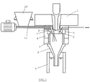
- the invention relates to a continuous casting process in which a flow of liquid metal is poured from a tundish into a ingot mould through the hollow jet nozzle (HJN).
- a hole is made through the dome 2 of the HJN, and in particular through one of the support arm 7 of the dome 2, to allow the injection of powder in the melt, as already known from the prior art.
- the metallic powder flowing through the hole is in direct contact with the refractory dome that is at a very high temperature (up to 1200°C).
- Inventors have discovered that despite the very short contact time between the particles and the refractory material, it is sufficient to gradually stick the particles together and to sinter them.
- a cluster of sintered powder is then formed after some minutes of casting and can lead to the full plugging of the powder injector. For example, an injection hole of 20 mm diameter is fully plugged after about 10 minutes of casting when using an iron powder with a size range between 100 and 180 ⁇ m.
- first means are provided to prevent a direct contact between the dome 2 at high temperature (approximately between 1000 and 1300°C) and the powder during injection.
- Said first means comprise a hollow body 12 extending inside the hole 6 of the dome 2, the powder being injected inside the hollow body 12 during casting.
- This hollow body 12 may have any suitable shape as long as it creates a physical barrier between the dome 2 and the powder.
- the hollow body may be a tube with a circular section; it can be made of a refractory material or metal such as low carbon steel.
- the inner diameter of said tube depends on the powder flow rate to be injected and can, for example, range from 8 to 30 mm for a powder flow rate between 1 and 7 kg/min.
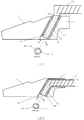
- second means are provided for preventing the sticking and sintering of the powder inside the hollow body. They are described in figures 2 to 5 in different embodiments. These second means according to the different embodiments allow reducing the surface temperature of the inner wall of the hollow body 12 and thereby reducing the heating of the powder.
- said hollow body 12 has a double wall 13 cooled by gas.
- the gas inlet and outlet in the double wall 13 are respectively illustrated by dashed arrows in figure 2 .
- the external and internal walls can have, for example, a thickness of 2 mm and the thickness of the gas film in the double wall can be of about 1.5 mm.
- the gas can be nitrogen or any other suitable gas and circulates usually in the double wall with a flow rate ranging from 10 to 30 m 3 /h. In a preferred embodiment said gas circulates in closed loop in order to avoid any gas injection inside the nozzle which could disturb the liquid steel flow and the good working of the casting equipment.
- the hollow body 12 can also be wrapped in an insulating layer 14 to create a thermal barrier between the hollow body 12 and the refractory dome 2.
- the continuous casting equipment can also be provided with means for measuring the temperature and the gas flow rate at the inlet and outlet of the cooling device.
- the powder feeder 11 which is preferably a screw feeder, is disposed above the dome 2.
- the hollow body 12 has the shape of a bent tube and the powder feeder 11 is partly located into said hollow body 12 inside the dome 2.
- the hollow body 12 with a shape of the bent tube can also goes through a support arm 7 of the dome 2 and the powder feeder 11 is partly located into said hollow body 12 and goes through said support arm 7. This configuration allows gaining space to reduce the size of the equipment.
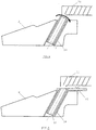
- the hollow body 12 is rotary mounted about the longitudinal axis of the hole.
- the rotation of the hollow body 12 allows creating shear stresses on the particles in order to avoid their possible sintering or sticking on the hollow body 12 and to obtain a cooling of the hollow body 12 by the heat exchange between this latter and the powder.
- the hollow body 12, as illustrated in figure 4 is a double wall hollow body as previously described, but in another embodiment, not illustrated, it could be a single tube without gas circulation.
- said hollow body 12 can be isolated from the refractory dome 2 by an insulating layer 14.
- the hollow body 12 is mounted in such a way that it may vibrate in the hole.
- the vibration applied to the hollow body 12 allows avoiding the formation of powder clusters inside the hollow body.
- the vibration can be generated by a mechanical vibrator, by ultrasounds or by other adequate means 15 creating high frequency vibrations, between 50 and 500HZ.
- the hollow body 12 can also be wrapped with an insulating layer 14 to reduce the inner surface temperature of the hollow body 12.
- the powder feeder 11 is located above the dome 2 but in another embodiment, not illustrated, it could be located into the hollow body 12 having a shape of a bent tube.
- the insulating layers can be made up of ceramic fibres which are resistant to high temperatures, such as 1300°C.
- the powder used for injection can be of any type, i.e. metallic or ceramic, or a mixture of different powder types.
Landscapes
- Engineering & Computer Science (AREA)
- Mechanical Engineering (AREA)
- Chemical & Material Sciences (AREA)
- Materials Engineering (AREA)
- Metallurgy (AREA)
- Organic Chemistry (AREA)
- Continuous Casting (AREA)
- Powder Metallurgy (AREA)
- Control And Other Processes For Unpacking Of Materials (AREA)
- Auxiliary Devices For And Details Of Packaging Control (AREA)
- Electric Connection Of Electric Components To Printed Circuits (AREA)
- Casting Support Devices, Ladles, And Melt Control Thereby (AREA)
Priority Applications (1)
| Application Number | Priority Date | Filing Date | Title |
|---|---|---|---|
| PL12719051T PL2830792T3 (pl) | 2012-03-28 | 2012-03-28 | Sposób ciągłego odlewania metalu |
Applications Claiming Priority (1)
| Application Number | Priority Date | Filing Date | Title |
|---|---|---|---|
| PCT/IB2012/000628 WO2013144668A1 (en) | 2012-03-28 | 2012-03-28 | Continuous casting process of metal |
Publications (2)
| Publication Number | Publication Date |
|---|---|
| EP2830792A1 EP2830792A1 (en) | 2015-02-04 |
| EP2830792B1 true EP2830792B1 (en) | 2019-02-20 |
Family
ID=46028006
Family Applications (1)
| Application Number | Title | Priority Date | Filing Date |
|---|---|---|---|
| EP12719051.0A Active EP2830792B1 (en) | 2012-03-28 | 2012-03-28 | Continuous casting process of metal |
Country Status (17)
| Country | Link |
|---|---|
| US (1) | US20150158078A1 (ja) |
| EP (1) | EP2830792B1 (ja) |
| JP (1) | JP5893796B2 (ja) |
| KR (2) | KR20160125529A (ja) |
| CN (1) | CN104220190B (ja) |
| AU (1) | AU2012375161C1 (ja) |
| BR (1) | BR112014023711B1 (ja) |
| CA (2) | CA2868147C (ja) |
| ES (1) | ES2727252T3 (ja) |
| HU (1) | HUE043371T2 (ja) |
| IN (1) | IN2014DN08195A (ja) |
| MX (1) | MX361679B (ja) |
| PL (1) | PL2830792T3 (ja) |
| RU (1) | RU2608253C2 (ja) |
| UA (1) | UA110573C2 (ja) |
| WO (1) | WO2013144668A1 (ja) |
| ZA (1) | ZA201406486B (ja) |
Families Citing this family (2)
| Publication number | Priority date | Publication date | Assignee | Title |
|---|---|---|---|---|
| DE102015116517A1 (de) * | 2015-09-29 | 2017-03-30 | Thyssenkrupp Ag | Vorrichtung und Verfahren zur kontinuierlichen Herstellung eines bandförmigen, metallischen Werkstücks |
| CN111451462B (zh) * | 2020-04-09 | 2021-09-28 | 苏州大学 | 利用浸入式水口喷吹镁粉细化连铸坯凝固组织的方法 |
Family Cites Families (21)
| Publication number | Priority date | Publication date | Assignee | Title |
|---|---|---|---|---|
| NL152933B (nl) * | 1969-06-23 | 1977-04-15 | Koninklijke Hoogovens En Staal | Werkwijze voor het desoxyderen van onrustig staal. |
| JPS49333Y1 (ja) * | 1970-09-18 | 1974-01-08 | ||
| SU416149A1 (ja) * | 1971-09-21 | 1974-02-25 | ||
| CH559075A5 (ja) * | 1973-05-30 | 1975-02-28 | Concast Ag | |
| US3911993A (en) * | 1974-07-12 | 1975-10-14 | Caterpillar Tractor Co | Method and apparatus for adding treating agents to molten metal |
| GB2096032A (en) * | 1981-04-07 | 1982-10-13 | Mitsubishi Steel Mfg | Continuously casting lead-containing steel |
| SU986588A1 (ru) * | 1981-04-13 | 1983-01-07 | Всесоюзный Научно-Исследовательский Институт Литейного Машиностроения,Литейной Технологии И Автоматизации Литейного Производства "Вниилитмаш" | Устройство дл модифицировани жидкого металла |
| US4520861A (en) * | 1983-11-18 | 1985-06-04 | Republic Steel Corporation | Method and apparatus for alloying continuously cast steel products |
| DE3508618A1 (de) * | 1985-03-29 | 1986-09-18 | Vasipari Kutató és Fejlesztö Vállalat, Budapest | Blaslanze zur behandlung von metallschmelzen in huettenwerksanlagen |
| ATE71004T1 (de) | 1986-11-26 | 1992-01-15 | Centre Rech Metallurgique | Vorrichtung zum giessen eines pastenartigen metalles. |
| US4941646A (en) * | 1988-11-23 | 1990-07-17 | Bethlehem Steel Corporation | Air cooled gas injection lance |
| JPH0745095B2 (ja) * | 1989-03-09 | 1995-05-17 | 黒崎窯業株式会社 | 連続鋳造用添加金属挿入方法及びこれに用いる浸漬ノズル |
| GB9023716D0 (en) * | 1990-10-31 | 1990-12-12 | Whellock John G | Metallurgical apparatus and methods |
| BE1006567A6 (fr) | 1992-12-28 | 1994-10-18 | Centre Rech Metallurgique | Procede de coulee d'un metal en phase pateuse. |
| FR2713116B1 (fr) * | 1993-11-30 | 1996-01-12 | Techmetal Promotion | Dispositif d'alimentation pour le dépôt par simple gravité d'un matériau granuleux sur la surface d'un métal liquide coulé en continu. |
| US6321766B1 (en) * | 1997-02-11 | 2001-11-27 | Richard D. Nathenson | Electromagnetic flow control valve for a liquid metal with built-in flow measurement |
| EP1452252A1 (en) * | 2003-02-28 | 2004-09-01 | Hubert Dipl.-Ing. Sommerhofer | Continuous casting method |
| BE1016550A3 (fr) * | 2005-03-16 | 2007-01-09 | Ct Rech Metallurgiques Asbl | Procede pour couler en continu un metal a resistance mecanique amelioree et produit obtenu par le procede. |
| KR100749026B1 (ko) * | 2006-06-23 | 2007-08-13 | 주식회사 포스코 | 용융 몰드플럭스를 이용한 연속 주조 장치 |
| BE1017392A3 (fr) | 2006-12-12 | 2008-08-05 | Ct Rech Metallurgiques Asbl | Busette a jet creux pour coulee continue d'acier. |
| EP2047926A1 (fr) * | 2007-10-10 | 2009-04-15 | Ugine & Alz France | Procéde de fabrication d'aciers inoxydables comportant de fins carbonitrures, et produit obtenu à partir de ce procédé |
-
2012
- 2012-03-28 KR KR1020167029170A patent/KR20160125529A/ko not_active Application Discontinuation
- 2012-03-28 PL PL12719051T patent/PL2830792T3/pl unknown
- 2012-03-28 AU AU2012375161A patent/AU2012375161C1/en active Active
- 2012-03-28 UA UAA201411656A patent/UA110573C2/ru unknown
- 2012-03-28 CA CA2868147A patent/CA2868147C/en active Active
- 2012-03-28 EP EP12719051.0A patent/EP2830792B1/en active Active
- 2012-03-28 IN IN8195DEN2014 patent/IN2014DN08195A/en unknown
- 2012-03-28 KR KR1020147027209A patent/KR20140129321A/ko active Application Filing
- 2012-03-28 CA CA2999637A patent/CA2999637C/en active Active
- 2012-03-28 HU HUE12719051A patent/HUE043371T2/hu unknown
- 2012-03-28 MX MX2014011705A patent/MX361679B/es active IP Right Grant
- 2012-03-28 RU RU2014143201A patent/RU2608253C2/ru active
- 2012-03-28 US US14/385,046 patent/US20150158078A1/en active Pending
- 2012-03-28 JP JP2015502465A patent/JP5893796B2/ja active Active
- 2012-03-28 WO PCT/IB2012/000628 patent/WO2013144668A1/en active Application Filing
- 2012-03-28 ES ES12719051T patent/ES2727252T3/es active Active
- 2012-03-28 CN CN201280072012.4A patent/CN104220190B/zh active Active
- 2012-03-28 BR BR112014023711-5A patent/BR112014023711B1/pt active IP Right Grant
-
2014
- 2014-09-04 ZA ZA2014/06486A patent/ZA201406486B/en unknown
Non-Patent Citations (1)
| Title |
|---|
| None * |
Also Published As
| Publication number | Publication date |
|---|---|
| JP5893796B2 (ja) | 2016-03-23 |
| EP2830792A1 (en) | 2015-02-04 |
| JP2015514585A (ja) | 2015-05-21 |
| UA110573C2 (ru) | 2016-01-12 |
| RU2608253C2 (ru) | 2017-01-17 |
| ES2727252T3 (es) | 2019-10-15 |
| HUE043371T2 (hu) | 2019-08-28 |
| MX2014011705A (es) | 2014-12-08 |
| WO2013144668A1 (en) | 2013-10-03 |
| CA2868147A1 (en) | 2013-10-03 |
| MX361679B (es) | 2018-12-13 |
| CA2868147C (en) | 2018-05-29 |
| CN104220190B (zh) | 2018-08-28 |
| AU2012375161B2 (en) | 2016-07-14 |
| IN2014DN08195A (ja) | 2015-05-01 |
| CN104220190A (zh) | 2014-12-17 |
| BR112014023711B1 (pt) | 2019-06-11 |
| KR20140129321A (ko) | 2014-11-06 |
| RU2014143201A (ru) | 2016-05-20 |
| PL2830792T3 (pl) | 2019-08-30 |
| AU2012375161A1 (en) | 2014-10-02 |
| AU2012375161C1 (en) | 2016-11-24 |
| ZA201406486B (en) | 2016-07-27 |
| CA2999637C (en) | 2020-07-07 |
| CA2999637A1 (en) | 2013-10-03 |
| WO2013144668A9 (en) | 2013-12-12 |
| US20150158078A1 (en) | 2015-06-11 |
| KR20160125529A (ko) | 2016-10-31 |
Similar Documents
| Publication | Publication Date | Title |
|---|---|---|
| EP2830793B1 (en) | Continuous casting equipment | |
| JPH04504981A (ja) | 反応性合金の誘導スカル紡糸 | |
| EP2830792B1 (en) | Continuous casting process of metal | |
| US20240316622A1 (en) | Continuous casting process of metal | |
| JP4296566B2 (ja) | 鋳造用鋳込装置 | |
| JPS648041B2 (ja) | ||
| JP2000326064A (ja) | 溶融金属の方向性凝固方法及びその装置 | |
| JPH0745095B2 (ja) | 連続鋳造用添加金属挿入方法及びこれに用いる浸漬ノズル | |
| KR101532827B1 (ko) | 전자기 교반 용해 원심분무 장치 | |
| JPH06179070A (ja) | 金属の噴射成形法及びその装置 | |
| RU2410189C1 (ru) | Способ разливки металла | |
| JP4216636B2 (ja) | 連続鋳造方法および連続鋳造装置 | |
| KR20130099721A (ko) | 분무 성형법을 이용한 합금소재 성형장치 및 성형방법 | |
| JPH04311510A (ja) | 金属粉末の製造方法および製造装置 | |
| JPH04308010A (ja) | 溶融金属の注湯方法および注湯装置 | |
| JP2003048045A (ja) | タンディッシュ内溶鋼の均一加熱方法 | |
| JPS6358666B2 (ja) | ||
| JP2002331338A (ja) | 溶融金属および合金の少量供給制御法および装置 | |
| JPS61266153A (ja) | クラツド鋼の製造方法 |
Legal Events
| Date | Code | Title | Description |
|---|---|---|---|
| PUAI | Public reference made under article 153(3) epc to a published international application that has entered the european phase |
Free format text: ORIGINAL CODE: 0009012 |
|
| 17P | Request for examination filed |
Effective date: 20140917 |
|
| AK | Designated contracting states |
Kind code of ref document: A1 Designated state(s): AL AT BE BG CH CY CZ DE DK EE ES FI FR GB GR HR HU IE IS IT LI LT LU LV MC MK MT NL NO PL PT RO RS SE SI SK SM TR |
|
| AX | Request for extension of the european patent |
Extension state: BA ME |
|
| DAX | Request for extension of the european patent (deleted) | ||
| 17Q | First examination report despatched |
Effective date: 20160104 |
|
| RAP1 | Party data changed (applicant data changed or rights of an application transferred) |
Owner name: ARCELORMITTAL |
|
| STAA | Information on the status of an ep patent application or granted ep patent |
Free format text: STATUS: EXAMINATION IS IN PROGRESS |
|
| GRAP | Despatch of communication of intention to grant a patent |
Free format text: ORIGINAL CODE: EPIDOSNIGR1 |
|
| STAA | Information on the status of an ep patent application or granted ep patent |
Free format text: STATUS: GRANT OF PATENT IS INTENDED |
|
| RIC1 | Information provided on ipc code assigned before grant |
Ipc: B22D 11/04 20060101ALI20180803BHEP Ipc: B22D 11/108 20060101AFI20180803BHEP Ipc: B22D 41/58 20060101ALI20180803BHEP Ipc: B22D 11/103 20060101ALI20180803BHEP |
|
| INTG | Intention to grant announced |
Effective date: 20180906 |
|
| GRAS | Grant fee paid |
Free format text: ORIGINAL CODE: EPIDOSNIGR3 |
|
| GRAA | (expected) grant |
Free format text: ORIGINAL CODE: 0009210 |
|
| STAA | Information on the status of an ep patent application or granted ep patent |
Free format text: STATUS: THE PATENT HAS BEEN GRANTED |
|
| AK | Designated contracting states |
Kind code of ref document: B1 Designated state(s): AL AT BE BG CH CY CZ DE DK EE ES FI FR GB GR HR HU IE IS IT LI LT LU LV MC MK MT NL NO PL PT RO RS SE SI SK SM TR |
|
| REG | Reference to a national code |
Ref country code: GB Ref legal event code: FG4D |
|
| REG | Reference to a national code |
Ref country code: CH Ref legal event code: EP |
|
| REG | Reference to a national code |
Ref country code: DE Ref legal event code: R096 Ref document number: 602012056796 Country of ref document: DE |
|
| REG | Reference to a national code |
Ref country code: AT Ref legal event code: REF Ref document number: 1097521 Country of ref document: AT Kind code of ref document: T Effective date: 20190315 |
|
| REG | Reference to a national code |
Ref country code: IE Ref legal event code: FG4D |
|
| REG | Reference to a national code |
Ref country code: RO Ref legal event code: EPE |
|
| REG | Reference to a national code |
Ref country code: SE Ref legal event code: TRGR |
|
| REG | Reference to a national code |
Ref country code: NL Ref legal event code: FP |
|
| REG | Reference to a national code |
Ref country code: LT Ref legal event code: MG4D |
|
| PG25 | Lapsed in a contracting state [announced via postgrant information from national office to epo] |
Ref country code: LT Free format text: LAPSE BECAUSE OF FAILURE TO SUBMIT A TRANSLATION OF THE DESCRIPTION OR TO PAY THE FEE WITHIN THE PRESCRIBED TIME-LIMIT Effective date: 20190220 Ref country code: PT Free format text: LAPSE BECAUSE OF FAILURE TO SUBMIT A TRANSLATION OF THE DESCRIPTION OR TO PAY THE FEE WITHIN THE PRESCRIBED TIME-LIMIT Effective date: 20190620 Ref country code: NO Free format text: LAPSE BECAUSE OF FAILURE TO SUBMIT A TRANSLATION OF THE DESCRIPTION OR TO PAY THE FEE WITHIN THE PRESCRIBED TIME-LIMIT Effective date: 20190520 |
|
| REG | Reference to a national code |
Ref country code: SK Ref legal event code: T3 Ref document number: E 30959 Country of ref document: SK |
|
| REG | Reference to a national code |
Ref country code: HU Ref legal event code: AG4A Ref document number: E043371 Country of ref document: HU |
|
| PG25 | Lapsed in a contracting state [announced via postgrant information from national office to epo] |
Ref country code: LV Free format text: LAPSE BECAUSE OF FAILURE TO SUBMIT A TRANSLATION OF THE DESCRIPTION OR TO PAY THE FEE WITHIN THE PRESCRIBED TIME-LIMIT Effective date: 20190220 Ref country code: GR Free format text: LAPSE BECAUSE OF FAILURE TO SUBMIT A TRANSLATION OF THE DESCRIPTION OR TO PAY THE FEE WITHIN THE PRESCRIBED TIME-LIMIT Effective date: 20190521 Ref country code: IS Free format text: LAPSE BECAUSE OF FAILURE TO SUBMIT A TRANSLATION OF THE DESCRIPTION OR TO PAY THE FEE WITHIN THE PRESCRIBED TIME-LIMIT Effective date: 20190620 Ref country code: HR Free format text: LAPSE BECAUSE OF FAILURE TO SUBMIT A TRANSLATION OF THE DESCRIPTION OR TO PAY THE FEE WITHIN THE PRESCRIBED TIME-LIMIT Effective date: 20190220 Ref country code: RS Free format text: LAPSE BECAUSE OF FAILURE TO SUBMIT A TRANSLATION OF THE DESCRIPTION OR TO PAY THE FEE WITHIN THE PRESCRIBED TIME-LIMIT Effective date: 20190220 Ref country code: BG Free format text: LAPSE BECAUSE OF FAILURE TO SUBMIT A TRANSLATION OF THE DESCRIPTION OR TO PAY THE FEE WITHIN THE PRESCRIBED TIME-LIMIT Effective date: 20190520 |
|
| REG | Reference to a national code |
Ref country code: ES Ref legal event code: FG2A Ref document number: 2727252 Country of ref document: ES Kind code of ref document: T3 Effective date: 20191015 |
|
| PG25 | Lapsed in a contracting state [announced via postgrant information from national office to epo] |
Ref country code: AL Free format text: LAPSE BECAUSE OF FAILURE TO SUBMIT A TRANSLATION OF THE DESCRIPTION OR TO PAY THE FEE WITHIN THE PRESCRIBED TIME-LIMIT Effective date: 20190220 Ref country code: EE Free format text: LAPSE BECAUSE OF FAILURE TO SUBMIT A TRANSLATION OF THE DESCRIPTION OR TO PAY THE FEE WITHIN THE PRESCRIBED TIME-LIMIT Effective date: 20190220 Ref country code: DK Free format text: LAPSE BECAUSE OF FAILURE TO SUBMIT A TRANSLATION OF THE DESCRIPTION OR TO PAY THE FEE WITHIN THE PRESCRIBED TIME-LIMIT Effective date: 20190220 |
|
| REG | Reference to a national code |
Ref country code: CH Ref legal event code: PL |
|
| REG | Reference to a national code |
Ref country code: DE Ref legal event code: R097 Ref document number: 602012056796 Country of ref document: DE |
|
| PG25 | Lapsed in a contracting state [announced via postgrant information from national office to epo] |
Ref country code: SM Free format text: LAPSE BECAUSE OF FAILURE TO SUBMIT A TRANSLATION OF THE DESCRIPTION OR TO PAY THE FEE WITHIN THE PRESCRIBED TIME-LIMIT Effective date: 20190220 Ref country code: LU Free format text: LAPSE BECAUSE OF NON-PAYMENT OF DUE FEES Effective date: 20190328 |
|
| PLBE | No opposition filed within time limit |
Free format text: ORIGINAL CODE: 0009261 |
|
| STAA | Information on the status of an ep patent application or granted ep patent |
Free format text: STATUS: NO OPPOSITION FILED WITHIN TIME LIMIT |
|
| PG25 | Lapsed in a contracting state [announced via postgrant information from national office to epo] |
Ref country code: MC Free format text: LAPSE BECAUSE OF FAILURE TO SUBMIT A TRANSLATION OF THE DESCRIPTION OR TO PAY THE FEE WITHIN THE PRESCRIBED TIME-LIMIT Effective date: 20190220 |
|
| 26N | No opposition filed |
Effective date: 20191121 |
|
| PG25 | Lapsed in a contracting state [announced via postgrant information from national office to epo] |
Ref country code: CH Free format text: LAPSE BECAUSE OF NON-PAYMENT OF DUE FEES Effective date: 20190331 Ref country code: LI Free format text: LAPSE BECAUSE OF NON-PAYMENT OF DUE FEES Effective date: 20190331 Ref country code: IE Free format text: LAPSE BECAUSE OF NON-PAYMENT OF DUE FEES Effective date: 20190328 |
|
| PG25 | Lapsed in a contracting state [announced via postgrant information from national office to epo] |
Ref country code: SI Free format text: LAPSE BECAUSE OF FAILURE TO SUBMIT A TRANSLATION OF THE DESCRIPTION OR TO PAY THE FEE WITHIN THE PRESCRIBED TIME-LIMIT Effective date: 20190220 |
|
| PG25 | Lapsed in a contracting state [announced via postgrant information from national office to epo] |
Ref country code: MT Free format text: LAPSE BECAUSE OF NON-PAYMENT OF DUE FEES Effective date: 20190328 |
|
| REG | Reference to a national code |
Ref country code: AT Ref legal event code: UEP Ref document number: 1097521 Country of ref document: AT Kind code of ref document: T Effective date: 20190220 |
|
| PG25 | Lapsed in a contracting state [announced via postgrant information from national office to epo] |
Ref country code: CY Free format text: LAPSE BECAUSE OF FAILURE TO SUBMIT A TRANSLATION OF THE DESCRIPTION OR TO PAY THE FEE WITHIN THE PRESCRIBED TIME-LIMIT Effective date: 20190220 |
|
| PG25 | Lapsed in a contracting state [announced via postgrant information from national office to epo] |
Ref country code: MK Free format text: LAPSE BECAUSE OF FAILURE TO SUBMIT A TRANSLATION OF THE DESCRIPTION OR TO PAY THE FEE WITHIN THE PRESCRIBED TIME-LIMIT Effective date: 20190220 |
|
| P01 | Opt-out of the competence of the unified patent court (upc) registered |
Effective date: 20230427 |
|
| PGFP | Annual fee paid to national office [announced via postgrant information from national office to epo] |
Ref country code: NL Payment date: 20240220 Year of fee payment: 13 |
|
| PGFP | Annual fee paid to national office [announced via postgrant information from national office to epo] |
Ref country code: AT Payment date: 20240222 Year of fee payment: 13 |
|
| PGFP | Annual fee paid to national office [announced via postgrant information from national office to epo] |
Ref country code: RO Payment date: 20240304 Year of fee payment: 13 Ref country code: HU Payment date: 20240311 Year of fee payment: 13 Ref country code: FI Payment date: 20240223 Year of fee payment: 13 Ref country code: DE Payment date: 20240220 Year of fee payment: 13 Ref country code: CZ Payment date: 20240226 Year of fee payment: 13 Ref country code: GB Payment date: 20240221 Year of fee payment: 13 Ref country code: SK Payment date: 20240228 Year of fee payment: 13 |
|
| PGFP | Annual fee paid to national office [announced via postgrant information from national office to epo] |
Ref country code: TR Payment date: 20240301 Year of fee payment: 13 Ref country code: SE Payment date: 20240220 Year of fee payment: 13 Ref country code: PL Payment date: 20240226 Year of fee payment: 13 Ref country code: IT Payment date: 20240220 Year of fee payment: 13 Ref country code: FR Payment date: 20240221 Year of fee payment: 13 Ref country code: BE Payment date: 20240220 Year of fee payment: 13 |
|
| PGFP | Annual fee paid to national office [announced via postgrant information from national office to epo] |
Ref country code: ES Payment date: 20240402 Year of fee payment: 13 |