EP2830404A2 - Cooling device - Google Patents
Cooling device Download PDFInfo
- Publication number
- EP2830404A2 EP2830404A2 EP20140175918 EP14175918A EP2830404A2 EP 2830404 A2 EP2830404 A2 EP 2830404A2 EP 20140175918 EP20140175918 EP 20140175918 EP 14175918 A EP14175918 A EP 14175918A EP 2830404 A2 EP2830404 A2 EP 2830404A2
- Authority
- EP
- European Patent Office
- Prior art keywords
- region
- cooling
- heat generating
- generating unit
- cooling device
- Prior art date
- Legal status (The legal status is an assumption and is not a legal conclusion. Google has not performed a legal analysis and makes no representation as to the accuracy of the status listed.)
- Granted
Links
- 238000001816 cooling Methods 0.000 title claims abstract description 67
- 239000000758 substrate Substances 0.000 claims description 7
- 239000004065 semiconductor Substances 0.000 description 5
- 230000002093 peripheral effect Effects 0.000 description 4
- XEEYBQQBJWHFJM-UHFFFAOYSA-N Iron Chemical compound [Fe] XEEYBQQBJWHFJM-UHFFFAOYSA-N 0.000 description 2
- 230000000694 effects Effects 0.000 description 2
- 238000012986 modification Methods 0.000 description 2
- 230000004048 modification Effects 0.000 description 2
- 229910000838 Al alloy Inorganic materials 0.000 description 1
- 230000004075 alteration Effects 0.000 description 1
- 229910052782 aluminium Inorganic materials 0.000 description 1
- XAGFODPZIPBFFR-UHFFFAOYSA-N aluminium Chemical compound [Al] XAGFODPZIPBFFR-UHFFFAOYSA-N 0.000 description 1
- 238000010276 construction Methods 0.000 description 1
- 239000000428 dust Substances 0.000 description 1
- 230000005669 field effect Effects 0.000 description 1
- 229910052742 iron Inorganic materials 0.000 description 1
- 229910044991 metal oxide Inorganic materials 0.000 description 1
- 150000004706 metal oxides Chemical class 0.000 description 1
Images
Classifications
-
- H—ELECTRICITY
- H05—ELECTRIC TECHNIQUES NOT OTHERWISE PROVIDED FOR
- H05K—PRINTED CIRCUITS; CASINGS OR CONSTRUCTIONAL DETAILS OF ELECTRIC APPARATUS; MANUFACTURE OF ASSEMBLAGES OF ELECTRICAL COMPONENTS
- H05K7/00—Constructional details common to different types of electric apparatus
- H05K7/20—Modifications to facilitate cooling, ventilating, or heating
- H05K7/2089—Modifications to facilitate cooling, ventilating, or heating for power electronics, e.g. for inverters for controlling motor
- H05K7/20909—Forced ventilation, e.g. on heat dissipaters coupled to components
-
- H—ELECTRICITY
- H05—ELECTRIC TECHNIQUES NOT OTHERWISE PROVIDED FOR
- H05K—PRINTED CIRCUITS; CASINGS OR CONSTRUCTIONAL DETAILS OF ELECTRIC APPARATUS; MANUFACTURE OF ASSEMBLAGES OF ELECTRICAL COMPONENTS
- H05K1/00—Printed circuits
- H05K1/02—Details
- H05K1/0201—Thermal arrangements, e.g. for cooling, heating or preventing overheating
-
- F—MECHANICAL ENGINEERING; LIGHTING; HEATING; WEAPONS; BLASTING
- F24—HEATING; RANGES; VENTILATING
- F24F—AIR-CONDITIONING; AIR-HUMIDIFICATION; VENTILATION; USE OF AIR CURRENTS FOR SCREENING
- F24F7/00—Ventilation
- F24F7/007—Ventilation with forced flow
-
- F—MECHANICAL ENGINEERING; LIGHTING; HEATING; WEAPONS; BLASTING
- F24—HEATING; RANGES; VENTILATING
- F24F—AIR-CONDITIONING; AIR-HUMIDIFICATION; VENTILATION; USE OF AIR CURRENTS FOR SCREENING
- F24F7/00—Ventilation
- F24F7/02—Roof ventilation
- F24F7/025—Roof ventilation with forced air circulation by means of a built-in ventilator
-
- H—ELECTRICITY
- H05—ELECTRIC TECHNIQUES NOT OTHERWISE PROVIDED FOR
- H05K—PRINTED CIRCUITS; CASINGS OR CONSTRUCTIONAL DETAILS OF ELECTRIC APPARATUS; MANUFACTURE OF ASSEMBLAGES OF ELECTRICAL COMPONENTS
- H05K7/00—Constructional details common to different types of electric apparatus
- H05K7/20—Modifications to facilitate cooling, ventilating, or heating
- H05K7/20009—Modifications to facilitate cooling, ventilating, or heating using a gaseous coolant in electronic enclosures
- H05K7/20136—Forced ventilation, e.g. by fans
- H05K7/20172—Fan mounting or fan specifications
Definitions
- the teachings in accordance with the exemplary embodiments of this present disclosure generally relate to a cooling device.
- an inverter configured to convert a DC (Direct Current) to an AC (Alternating Current) generates a large amount of heat from a power semiconductor and peripherals thereof.
- the inverter is mounted with a heat sink for cooling a power semiconductor, where a forced cooling method using a cooling fan is used for the heat sink while a natural cooling method is used for peripherals that generate heat.
- a forced cooling method using a cooling fan is used for the heat sink while a natural cooling method is used for peripherals that generate heat.
- the peripherals may be over-heated to decrease performance of the product or damage the product, when the natural cooling method is used to cool the peripherals.
- An exemplary embodiment of the present disclosure is to provide a cooling device configured in such a manner that a heat generating unit arranged in an open space and coupled to a heat radiating member like a heat sink is forcibly cooled using an outside air, and a heat generating unit arranged in a closed space and not coupled to a heat sink is forcibly cooled using circulation of inside air, whereby a cooling efficiency of the heat generating unit can be enhanced.
- a cooling device comprising:
- the case may include a separator configured to separate the first region from the second region.
- the cooling device may further comprise a circuit substrate arranged at an upper surface of the separator to be coupled to the first heat generating unit.
- the first cooling unit may include a heat sink coupled to the first heat generating unit and a cooling fan configured to introduce the outside air to the first region
- the second cooling unit includes a support plate configured to support the second heat generating unit, and a circulation fan configured to circulate the inside air into the second region.
- At least one distal end of one side of the support plate may be distanced from a lateral surface plate of the case, and the support plate may be formed with an opening coupled by the circulation fan.
- the circulation fan may be arranged in parallel with the support plate.
- the circulation fan may be slantly arranged relative to the support plate.
- the cooling device has an advantageous effect in that a heat generating unit arranged in an open space and coupled to a heat radiating member like a heat sink is forcibly cooled using an outside air, and a heat generating unit arranged in a closed space and not coupled to a heat sink is forcibly cooled using circulation of inside air.
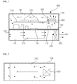
- FIG. 1 is a cross-sectional view illustrating a cooling device according to an exemplary embodiment of the present disclosure
- FIG. 2 is a plan view illustrating a circulation fan and a support plate of FIG. 1 .
- the cooling device (600) includes a case (100), a first cooling unit (200) and a second cooling unit (300).
- the cooling device (600) according to an exemplary embodiment of the present disclosure may be widely installed on an industrial electronic products or home electronic appliances. Now, the explanation of the cooling device (600) according to an exemplary embodiment of the present disclosure is provided on an assumption that the cooling device (600) is installed on an inverter, as an industrial electronic product, that changes a DC to an AC having a frequency and a voltage that require a commercial AC power.
- the case (100) provides a space for accommodating devices for implementing an inerter operation and the first/second cooling units (200, 300).
- the case (100) in the exemplary embodiment of the present disclosure may be divided into two spaces, for example.
- the two spaces are defined as a first region (FR) and a second region (SR) separated from the first region (FR), where the first region (FR) may be an open space and the second region (SR) may be a closed space, for example.
- the case (100) may be formed with a separator configured to separate the first region from the second region.
- the separator (110) is arranged at a center of the case (100), and the case (100) is divided into two sections, that is the first region (FR) and the second region (SR).
- the second region (SR) is arranged at an upper surface of the first region (FR) by the separator (110), and a part of the separator (110) is formed with an opening, where the opening formed by the separator (110) allows a first heat generating unit arranged at the second region (SR) to be coupled to a heat sink arranged at the first region (FR).
- openings (120, 130) configured to introduce an outside air to and discharge the outside air from the first region (FR) are formed at an area corresponding to the first region (FR) of the case (100), where the second region (SR) is air-tightly closed to prevent entrance of foreign objects such as dust and the like.
- an upper surface of the separator (110) dividing an interior of the case (100) into the first and second regions (FR, SR) is arranged with a circuit substrate (140).
- the circuit substrate (140) is formed at an upper surface with a first heat generating unit (150), where the circuit substrate (140) and the first heat generating unit (15) are electrically connected.
- the first heat generating unit (150) may include a power semiconductor, and the first heat generating unit (150) may include an IGBT (Insulated Gate Bipolar Transistor), for example.
- the first heat generating unit (150) may include MOSFET (Metal Oxide Semiconductor Field Effect Transistor).
- the first cooling unit (200) serves to cool the first heat generating unit (150).
- the first cooling unit (200) may be arranged at the first region (FR).
- the first cooling unit (200) arranged at the first region (FR) may include a heat sink (210) and a cooling fan (220).
- the heat sink (210) may include aluminum or aluminum alloy having a higher heat conductivity than iron, and the heat sink (210) is coupled to the first heat generating unit (150) electrically connected to the circuit substrate (140) and radiates heat generated from the first heat generating unit (150) to the first region (FR).
- the cooling fan (220) is arranged at the first region (FR), and the cooling fan (220) is arranged near to the opening (130) formed at the first region (FR).
- the cooling fan (220) serves to discharge an outside air to outside of the first region (FR). At this time, the outside air is introduced into the first region (FR) and heated via the heat sink (210).
- the outside air introduced into the first region (FR) by the cooling fan (220) serves to cool the heat sink (210), whereby the first heat generating unit (150) coupled to the heat sink (210) is forcibly cooled by the cooling fan (220).
- the second cooling unit (300) may be arranged at the second region (SR) in order to cool the second heat generating unit (170) arranged at the second region (SR).
- the second heat generating unit (170) may include a circuit substrate and at least one control module including control semiconductor chips, for example.
- the second cooling unit (300) cools the second heat generating unit (170) by circulating an inside air circulating in the second heat generating unit (170) arranged at the closed second region (SR).
- the second cooling unit (300) may include a support plate (310) and a circulation fan (320) in order to cool the heat generating unit (170) in a circulation cooling method.
- the support plate (310) is arranged at the second region (SR), and the support plate (310) is secured at a position distanced from the separator (110), an opening is formed at one side of the support plate (310) and the circulation fan (320, described later) is arranged at a position corresponding to the opening.
- the support plate (310) may be arranged in parallel with the separator (110), a distal end of the support plate (310) may be distanced from the case, and the separator (110) may be formed with the second heat generating unit (170).
- the circulation fan (320) may be coupled to the support plate (31), the circulation fan (320) may be arranged at a position corresponding to the opening of the support plate (310), and the circulation fan (320) may be arranged in parallel with the support plate (310) and the separator (110).
- the inside air of the second region (SR) is circulated by operation of the circulation fan (320), because a distal end of the support plat (310) is distanced from the case (100) and the opening formed at the support plate (310) is coupled to the circulation fan (320).
- the first region (FR) arranged with the heat sink (210) is performed with a forcible cooling of the first heat generating unit (150) using an outside air by the cooling fan (220), and the closed second region (SR) is performed with the circulatory cooling of the second heat generating unit (170) by the inside air circulated by the circulation fan (320), whereby cooling efficiency of the first and second heat generating units (150, 170) can be further enhanced.
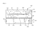
- FIG. 3 is a cross-sectional view illustrating a cooling device according to another exemplary embodiment of the present disclosure.
- the configuration of the cooling device according to another exemplary embodiment of the present disclosure is substantially same as that of FIGS. 1 and 2 except for arrangement of circulation fan. Thus, no redundant explanation on the same structure will be omitted, and, like reference numerals in FIG. 3 denote like elements.
- the circulation fan (320) may be slantly arranged or may be arranged to a slant direction relative to the support plate (310) in order to better circulate the inside air of the second region (SR), whereby the inside air of the second region (SR) can be more actively circulated by the circulation fan (320).
- a heat generating unit arranged at an opened space and coupled to heat radiating members like a heat sink is forcibly cooled using an outside air
- a heat generating unit arranged at a closed space and not coupled to the heat sink is forcibly cooled by circulation of inside air, whereby the cooling efficiency of heat units can be further enhanced by forced cooling.
Abstract
Description
- The teachings in accordance with the exemplary embodiments of this present disclosure generally relate to a cooling device.
- Generally, industrial electronic products or home electronic appliances are mounted with heat generating elements that generate a large amount of heat. For example, an inverter configured to convert a DC (Direct Current) to an AC (Alternating Current) generates a large amount of heat from a power semiconductor and peripherals thereof.
- The inverter is mounted with a heat sink for cooling a power semiconductor, where a forced cooling method using a cooling fan is used for the heat sink while a natural cooling method is used for peripherals that generate heat. However, the peripherals may be over-heated to decrease performance of the product or damage the product, when the natural cooling method is used to cool the peripherals.
- An exemplary embodiment of the present disclosure is to provide a cooling device configured in such a manner that a heat generating unit arranged in an open space and coupled to a heat radiating member like a heat sink is forcibly cooled using an outside air, and a heat generating unit arranged in a closed space and not coupled to a heat sink is forcibly cooled using circulation of inside air, whereby a cooling efficiency of the heat generating unit can be enhanced.
- Technical subjects to be solved by the present disclosure are not restricted to the above-mentioned problems, and any other technical problems not mentioned so far will be clearly appreciated from the following description by a person skilled in the art.
- In one general aspect of the present disclosure, there is provided a cooling device, the cooling device comprising:
- a case including a first region and a second region isolated from the first region;
- a first cooling unit arranged at the first region to cool a first heat generating unit using an outside air; and
- a second cooling unit arranged at the second region to cool a second heat generating unit using inside air.
- Preferably, but not necessarily, the case may include a separator configured to separate the first region from the second region.
- Preferably, but not necessarily, the cooling device may further comprise a circuit substrate arranged at an upper surface of the separator to be coupled to the first heat generating unit.
- Preferably, but not necessarily, the first cooling unit may include a heat sink coupled to the first heat generating unit and a cooling fan configured to introduce the outside air to the first region, and the second cooling unit includes a support plate configured to support the second heat generating unit, and a circulation fan configured to circulate the inside air into the second region.
- Preferably, but not necessarily, at least one distal end of one side of the support plate may be distanced from a lateral surface plate of the case, and the support plate may be formed with an opening coupled by the circulation fan.
- Preferably, but not necessarily, the circulation fan may be arranged in parallel with the support plate.
- Preferably, but not necessarily, the circulation fan may be slantly arranged relative to the support plate.
- The cooling device according to an exemplary embodiment of the present disclosure has an advantageous effect in that a heat generating unit arranged in an open space and coupled to a heat radiating member like a heat sink is forcibly cooled using an outside air, and a heat generating unit arranged in a closed space and not coupled to a heat sink is forcibly cooled using circulation of inside air.
-
-
FIG. 1 is a cross-sectional view illustrating a cooling device according to an exemplary embodiment of the present disclosure. -
FIG. 2 is a plan view illustrating a circulation fan and a support plate ofFIG. 1 . -
FIG. 3 is a cross-sectional view illustrating a cooling device according to another exemplary embodiment of the present disclosure. - A cooling device according to exemplary embodiments of the present disclosure will be described more fully hereinafter with reference to the accompanying drawings.
- Detailed descriptions of well-known functions, configurations or constructions are omitted for brevity and clarity so as not to obscure the description of the present disclosure with unnecessary detail. In the drawings, the width, length, thickness, etc. of components may be exaggerated or reduced for the sake of convenience. The present inventive concept may, however, be embodied in many different forms and should not be construed as limited to the example embodiments set forth herein. Rather, the described aspect is intended to embrace all such alterations, modifications, and variations that fall within the scope and novel idea of the present disclosure.
-
FIG. 1 is a cross-sectional view illustrating a cooling device according to an exemplary embodiment of the present disclosure, andFIG. 2 is a plan view illustrating a circulation fan and a support plate ofFIG. 1 . - Referring to
FIGS. 1 and 2 , the cooling device (600) includes a case (100), a first cooling unit (200) and a second cooling unit (300). The cooling device (600) according to an exemplary embodiment of the present disclosure may be widely installed on an industrial electronic products or home electronic appliances. Now, the explanation of the cooling device (600) according to an exemplary embodiment of the present disclosure is provided on an assumption that the cooling device (600) is installed on an inverter, as an industrial electronic product, that changes a DC to an AC having a frequency and a voltage that require a commercial AC power. - The case (100) provides a space for accommodating devices for implementing an inerter operation and the first/second cooling units (200, 300). The case (100) in the exemplary embodiment of the present disclosure may be divided into two spaces, for example. Hereinafter, the two spaces are defined as a first region (FR) and a second region (SR) separated from the first region (FR), where the first region (FR) may be an open space and the second region (SR) may be a closed space, for example.
- In order to form two spaces inside the case (100), the case (100) may be formed with a separator configured to separate the first region from the second region. The separator (110) is arranged at a center of the case (100), and the case (100) is divided into two sections, that is the first region (FR) and the second region (SR).
- The second region (SR) is arranged at an upper surface of the first region (FR) by the separator (110), and a part of the separator (110) is formed with an opening, where the opening formed by the separator (110) allows a first heat generating unit arranged at the second region (SR) to be coupled to a heat sink arranged at the first region (FR).
- In the exemplary embodiment of the present disclosure, openings (120, 130) configured to introduce an outside air to and discharge the outside air from the first region (FR) are formed at an area corresponding to the first region (FR) of the case (100), where the second region (SR) is air-tightly closed to prevent entrance of foreign objects such as dust and the like.
- Meantime, an upper surface of the separator (110) dividing an interior of the case (100) into the first and second regions (FR, SR) is arranged with a circuit substrate (140). The circuit substrate (140) is formed at an upper surface with a first heat generating unit (150), where the circuit substrate (140) and the first heat generating unit (15) are electrically connected.
- In the exemplary embodiment of the present disclosure, the first heat generating unit (150) may include a power semiconductor, and the first heat generating unit (150) may include an IGBT (Insulated Gate Bipolar Transistor), for example. Alternatively, the first heat generating unit (150) may include MOSFET (Metal Oxide Semiconductor Field Effect Transistor).
- The first cooling unit (200) serves to cool the first heat generating unit (150). In the exemplary embodiment of the present disclosure, the first cooling unit (200) may be arranged at the first region (FR). The first cooling unit (200) arranged at the first region (FR) may include a heat sink (210) and a cooling fan (220).
- The heat sink (210) may include aluminum or aluminum alloy having a higher heat conductivity than iron, and the heat sink (210) is coupled to the first heat generating unit (150) electrically connected to the circuit substrate (140) and radiates heat generated from the first heat generating unit (150) to the first region (FR).
- The cooling fan (220) is arranged at the first region (FR), and the cooling fan (220) is arranged near to the opening (130) formed at the first region (FR). The cooling fan (220) serves to discharge an outside air to outside of the first region (FR). At this time, the outside air is introduced into the first region (FR) and heated via the heat sink (210). The outside air introduced into the first region (FR) by the cooling fan (220) serves to cool the heat sink (210), whereby the first heat generating unit (150) coupled to the heat sink (210) is forcibly cooled by the cooling fan (220).
- The second cooling unit (300) may be arranged at the second region (SR) in order to cool the second heat generating unit (170) arranged at the second region (SR). In the exemplary embodiment of the present disclosure, the second heat generating unit (170) may include a circuit substrate and at least one control module including control semiconductor chips, for example.
- The second cooling unit (300) cools the second heat generating unit (170) by circulating an inside air circulating in the second heat generating unit (170) arranged at the closed second region (SR). The second cooling unit (300) may include a support plate (310) and a circulation fan (320) in order to cool the heat generating unit (170) in a circulation cooling method.
- The support plate (310) is arranged at the second region (SR), and the support plate (310) is secured at a position distanced from the separator (110), an opening is formed at one side of the support plate (310) and the circulation fan (320, described later) is arranged at a position corresponding to the opening. The support plate (310) may be arranged in parallel with the separator (110), a distal end of the support plate (310) may be distanced from the case, and the separator (110) may be formed with the second heat generating unit (170).
- The circulation fan (320) may be coupled to the support plate (31), the circulation fan (320) may be arranged at a position corresponding to the opening of the support plate (310), and the circulation fan (320) may be arranged in parallel with the support plate (310) and the separator (110).
- The inside air of the second region (SR) is circulated by operation of the circulation fan (320), because a distal end of the support plat (310) is distanced from the case (100) and the opening formed at the support plate (310) is coupled to the circulation fan (320).
- In the exemplary embodiment of the present disclosure, the first region (FR) arranged with the heat sink (210) is performed with a forcible cooling of the first heat generating unit (150) using an outside air by the cooling fan (220), and the closed second region (SR) is performed with the circulatory cooling of the second heat generating unit (170) by the inside air circulated by the circulation fan (320), whereby cooling efficiency of the first and second heat generating units (150, 170) can be further enhanced.
-
FIG. 3 is a cross-sectional view illustrating a cooling device according to another exemplary embodiment of the present disclosure. - The configuration of the cooling device according to another exemplary embodiment of the present disclosure is substantially same as that of
FIGS. 1 and 2 except for arrangement of circulation fan. Thus, no redundant explanation on the same structure will be omitted, and, like reference numerals inFIG. 3 denote like elements. - Referring to
FIG.3 , the circulation fan (320) may be slantly arranged or may be arranged to a slant direction relative to the support plate (310) in order to better circulate the inside air of the second region (SR), whereby the inside air of the second region (SR) can be more actively circulated by the circulation fan (320). - As apparent from the foregoing, a heat generating unit arranged at an opened space and coupled to heat radiating members like a heat sink is forcibly cooled using an outside air, and a heat generating unit arranged at a closed space and not coupled to the heat sink is forcibly cooled by circulation of inside air, whereby the cooling efficiency of heat units can be further enhanced by forced cooling.
- Although the present disclosure has been described in detail with reference to the foregoing embodiments and advantages, many alternatives, modifications, and variations will be apparent to those skilled in the art within the metes and bounds of the claims. Therefore, it should be understood that the above-described embodiments are not limited by any of the details of the foregoing description, unless otherwise specified, but rather should be construed broadly within the scope as defined in the appended claims
Claims (7)
- A cooling device, the cooling device characterized by:a case (100) including a first region (FR) and a second region (SR) isolated from the first region;a first cooling unit (200) arranged at the first region (FR) to cool a first heat generating unit (150) using an outside air; anda second cooling unit (300) arranged at the second region (SR) to cool a second heat generating unit (170) using inside air.
- The cooling device of claim 1, wherein the case (100) includes a separator (110) configured to separate the first region (FR) from the second region (SR).
- The cooling device of claim 2, further comprising a circuit substrate (140) arranged at an upper surface of the separator (110) to be coupled to the first heat generating unit (150).
- The cooling device of claim 1, wherein the first cooling unit (200) includes a heat sink (210) coupled to the first heat generating unit (150) and a cooling fan (220) configured to introduce the outside air to the first region (FR), and the second cooling unit (300) includes a support plate (310) configured to support the second heat generating unit (170), and a circulation fan (320) configured to circulate the inside air into the second region (SR).
- The cooling device of claim 4, wherein at least one distal end of one side of the support plate (310) is distanced from a lateral surface plate of the case (100), and the support plate (310) is formed with an opening coupled by the circulation fan (320).
- The cooling device of claim 4, wherein the circulation fan (320) is arranged in parallel with the support plate (310).
- The cooling device of claim 4, wherein the circulation fan (320) is slantly arranged relative to the support plate (310).
Applications Claiming Priority (1)
| Application Number | Priority Date | Filing Date | Title |
|---|---|---|---|
| KR1020130086119A KR20150011176A (en) | 2013-07-22 | 2013-07-22 | Cooling device |
Publications (3)
| Publication Number | Publication Date |
|---|---|
| EP2830404A2 true EP2830404A2 (en) | 2015-01-28 |
| EP2830404A3 EP2830404A3 (en) | 2015-03-25 |
| EP2830404B1 EP2830404B1 (en) | 2019-11-06 |
Family
ID=51063334
Family Applications (1)
| Application Number | Title | Priority Date | Filing Date |
|---|---|---|---|
| EP14175918.3A Active EP2830404B1 (en) | 2013-07-22 | 2014-07-07 | Cooling device |
Country Status (6)
| Country | Link |
|---|---|
| US (1) | US20150022972A1 (en) |
| EP (1) | EP2830404B1 (en) |
| JP (1) | JP2015021725A (en) |
| KR (1) | KR20150011176A (en) |
| CN (1) | CN104333997B (en) |
| ES (1) | ES2767339T3 (en) |
Cited By (2)
| Publication number | Priority date | Publication date | Assignee | Title |
|---|---|---|---|---|
| EP3468025B1 (en) * | 2016-06-01 | 2022-01-05 | Mitsubishi Electric Corporation | Power conversion device |
| EP4037136A1 (en) * | 2021-01-28 | 2022-08-03 | Andreas Stihl AG & Co. KG | Outdoorbox, system and use of outdoorbox and / or system |
Families Citing this family (20)
| Publication number | Priority date | Publication date | Assignee | Title |
|---|---|---|---|---|
| JP5914689B2 (en) * | 2012-10-30 | 2016-05-11 | 株式会社三社電機製作所 | Fan control device and power conditioner |
| US9545037B2 (en) * | 2014-01-24 | 2017-01-10 | Baker Hughes Incorporated | Systems and methods for cooling electric drives |
| US9961797B2 (en) * | 2014-09-15 | 2018-05-01 | Bloom Energy Corporation | Air cooled fuel cell system |
| WO2016132481A1 (en) * | 2015-02-18 | 2016-08-25 | 三菱電機株式会社 | Waterproof power conversion device and waterproof diagnosis method for waterproof power conversion device |
| KR101559536B1 (en) * | 2015-03-13 | 2015-10-15 | ㈜티앤이코리아 | Blowing System |
| CN106256176B (en) * | 2015-04-03 | 2017-12-05 | 三菱电机株式会社 | Electronic equipment |
| EP3079451B1 (en) * | 2015-04-09 | 2017-08-02 | ABB Schweiz AG | Cooled power conversion assembly |
| DE102015105500B3 (en) * | 2015-04-10 | 2016-09-08 | Rittal Gmbh & Co. Kg | Cooling unit for cabinet climate control |
| US10418654B2 (en) | 2015-09-08 | 2019-09-17 | Bloom Energy Corporation | Fuel cell ventilation systems |
| JP2017158413A (en) * | 2016-03-04 | 2017-09-07 | 富士電機株式会社 | Sealing container and power conversion device |
| JP6700978B2 (en) * | 2016-05-30 | 2020-05-27 | 三菱電機株式会社 | Power converter |
| JP6818231B2 (en) * | 2016-11-28 | 2021-01-20 | 株式会社Gsユアサ | Power supply |
| JP6861083B2 (en) * | 2017-04-24 | 2021-04-21 | 株式会社キューヘン | Static power compensator using power converter and power converter |
| WO2019107358A1 (en) * | 2017-11-30 | 2019-06-06 | 株式会社村田製作所 | Sealed-type electronic device |
| FR3075563B1 (en) * | 2017-12-18 | 2023-09-01 | Ifp Energies Now | FLOW-COOLED POWER ELECTRONICS |
| US10849252B2 (en) * | 2018-04-18 | 2020-11-24 | Delta Electronics, Inc. | Converter |
| DE102019120031A1 (en) * | 2019-07-24 | 2021-01-28 | Elringklinger Ag | Control device |
| JPWO2021070244A1 (en) * | 2019-10-08 | 2021-10-21 | 三菱電機株式会社 | Power converter |
| US11690195B2 (en) | 2020-09-11 | 2023-06-27 | Abb Schweiz Ag | Power semiconductor cooling system |
| KR20220135867A (en) * | 2021-03-31 | 2022-10-07 | 엘에스일렉트릭(주) | Solid State Circuit Breaker |
Family Cites Families (13)
| Publication number | Priority date | Publication date | Assignee | Title |
|---|---|---|---|---|
| JPS58175646U (en) * | 1982-05-20 | 1983-11-24 | 株式会社明電舎 | Heat sink installation structure |
| DE9111434U1 (en) * | 1991-09-12 | 1991-12-05 | Elpro Ag Berlin - Industrieelektronik Und Anlagenbau -, O-1140 Berlin, De | |
| JPH09246766A (en) * | 1996-03-13 | 1997-09-19 | Fanuc Ltd | Enclosed electronic equipment case |
| US5991153A (en) * | 1997-10-31 | 1999-11-23 | Lacerta Enterprises, Inc. | Heat transfer system and method for electronic displays |
| JPH11238986A (en) * | 1998-02-20 | 1999-08-31 | Mitsubishi Electric Corp | Cooling device for heat generating component |
| JP2000315880A (en) * | 1999-05-06 | 2000-11-14 | Toshiba Corp | Circuit-accommodating body |
| JP2005236099A (en) * | 2004-02-20 | 2005-09-02 | Nec Corp | Heat insulating method of electronic device cabinet, and electronic device housing type heat exchange structure applying the method thereto |
| FR2881018B1 (en) * | 2005-01-19 | 2007-04-06 | Intelligent Electronic Systems | METHOD FOR COOLING A STATIC POWER CONVERSION DEVICE AND CORRESPONDING DEVICE |
| JP5556288B2 (en) * | 2010-03-24 | 2014-07-23 | パナソニック株式会社 | Heat dissipation unit and electronic device using the same |
| EP2509304A1 (en) * | 2009-12-03 | 2012-10-10 | Panasonic Corporation | Radiation unit of electronic device and electronic device using same |
| JP2011138960A (en) * | 2009-12-28 | 2011-07-14 | Toshiba Corp | Power converter for vehicle |
| JP2011249495A (en) * | 2010-05-26 | 2011-12-08 | Daihen Corp | Power supply device |
| JP5430515B2 (en) * | 2010-07-30 | 2014-03-05 | 三菱電機株式会社 | Inverter |
-
2013
- 2013-07-22 KR KR1020130086119A patent/KR20150011176A/en not_active Application Discontinuation
-
2014
- 2014-06-30 US US14/320,394 patent/US20150022972A1/en not_active Abandoned
- 2014-07-07 EP EP14175918.3A patent/EP2830404B1/en active Active
- 2014-07-07 ES ES14175918T patent/ES2767339T3/en active Active
- 2014-07-18 JP JP2014147687A patent/JP2015021725A/en active Pending
- 2014-07-22 CN CN201410350633.5A patent/CN104333997B/en active Active
Non-Patent Citations (1)
| Title |
|---|
| None |
Cited By (2)
| Publication number | Priority date | Publication date | Assignee | Title |
|---|---|---|---|---|
| EP3468025B1 (en) * | 2016-06-01 | 2022-01-05 | Mitsubishi Electric Corporation | Power conversion device |
| EP4037136A1 (en) * | 2021-01-28 | 2022-08-03 | Andreas Stihl AG & Co. KG | Outdoorbox, system and use of outdoorbox and / or system |
Also Published As
| Publication number | Publication date |
|---|---|
| EP2830404A3 (en) | 2015-03-25 |
| CN104333997A (en) | 2015-02-04 |
| CN104333997B (en) | 2017-09-08 |
| ES2767339T3 (en) | 2020-06-17 |
| JP2015021725A (en) | 2015-02-02 |
| US20150022972A1 (en) | 2015-01-22 |
| EP2830404B1 (en) | 2019-11-06 |
| KR20150011176A (en) | 2015-01-30 |
Similar Documents
| Publication | Publication Date | Title |
|---|---|---|
| EP2830404A2 (en) | Cooling device | |
| US8634193B2 (en) | Device and method using induction to improve natural convection cooling | |
| US9795067B2 (en) | Electronic apparatus | |
| KR101189451B1 (en) | Inverter stack | |
| US9974214B2 (en) | Cooled power conversion assembly | |
| US20150319839A1 (en) | Device having heat sink | |
| KR101541181B1 (en) | Inverter and Converter for Electric Vehicle | |
| US20150062812A1 (en) | Apparatus for cooling inverter | |
| US10560985B2 (en) | Induction heat cooking apparatus | |
| EP3518639B1 (en) | Inverter and method of controlling the same | |
| US20190305649A1 (en) | Motor driving device and air conditioner | |
| US20180295748A1 (en) | Electronics assemblies incorporating three-dimensional heat flow structures | |
| US10098256B2 (en) | Electronic device | |
| KR101800048B1 (en) | Cooling device for invertor | |
| JP2013252006A (en) | Motor driving device and air conditioner including the same | |
| JP4215095B2 (en) | Electromagnetic cooker | |
| WO2019107358A1 (en) | Sealed-type electronic device | |
| JP4215096B2 (en) | Electromagnetic cooker | |
| KR20180002663U (en) | Thermal radiating structure | |
| US20120002452A1 (en) | Compact inverter | |
| JP4636100B2 (en) | Electromagnetic cooker | |
| JPS5855834Y2 (en) | Air-cooled electrical equipment | |
| JP2007080840A (en) | Electromagnetic cooker | |
| JP2018207578A (en) | Dc/dc converter integrated inverter device |
Legal Events
| Date | Code | Title | Description |
|---|---|---|---|
| 17P | Request for examination filed |
Effective date: 20140707 |
|
| AK | Designated contracting states |
Kind code of ref document: A2 Designated state(s): AL AT BE BG CH CY CZ DE DK EE ES FI FR GB GR HR HU IE IS IT LI LT LU LV MC MK MT NL NO PL PT RO RS SE SI SK SM TR |
|
| AX | Request for extension of the european patent |
Extension state: BA ME |
|
| PUAI | Public reference made under article 153(3) epc to a published international application that has entered the european phase |
Free format text: ORIGINAL CODE: 0009012 |
|
| PUAL | Search report despatched |
Free format text: ORIGINAL CODE: 0009013 |
|
| RIN1 | Information on inventor provided before grant (corrected) |
Inventor name: KWON, HYUK IL |
|
| AK | Designated contracting states |
Kind code of ref document: A3 Designated state(s): AL AT BE BG CH CY CZ DE DK EE ES FI FR GB GR HR HU IE IS IT LI LT LU LV MC MK MT NL NO PL PT RO RS SE SI SK SM TR |
|
| AX | Request for extension of the european patent |
Extension state: BA ME |
|
| RIC1 | Information provided on ipc code assigned before grant |
Ipc: F24F 7/007 20060101ALI20150218BHEP Ipc: H05K 7/20 20060101AFI20150218BHEP Ipc: H05K 1/02 20060101ALI20150218BHEP |
|
| R17P | Request for examination filed (corrected) |
Effective date: 20150918 |
|
| RBV | Designated contracting states (corrected) |
Designated state(s): AL AT BE BG CH CY CZ DE DK EE ES FI FR GB GR HR HU IE IS IT LI LT LU LV MC MK MT NL NO PL PT RO RS SE SI SK SM TR |
|
| STAA | Information on the status of an ep patent application or granted ep patent |
Free format text: STATUS: EXAMINATION IS IN PROGRESS |
|
| 17Q | First examination report despatched |
Effective date: 20180503 |
|
| GRAP | Despatch of communication of intention to grant a patent |
Free format text: ORIGINAL CODE: EPIDOSNIGR1 |
|
| STAA | Information on the status of an ep patent application or granted ep patent |
Free format text: STATUS: GRANT OF PATENT IS INTENDED |
|
| INTG | Intention to grant announced |
Effective date: 20190627 |
|
| RAP1 | Party data changed (applicant data changed or rights of an application transferred) |
Owner name: LSIS CO., LTD. |
|
| RIN1 | Information on inventor provided before grant (corrected) |
Inventor name: KWON, HYUK IL |
|
| GRAS | Grant fee paid |
Free format text: ORIGINAL CODE: EPIDOSNIGR3 |
|
| GRAA | (expected) grant |
Free format text: ORIGINAL CODE: 0009210 |
|
| STAA | Information on the status of an ep patent application or granted ep patent |
Free format text: STATUS: THE PATENT HAS BEEN GRANTED |
|
| AK | Designated contracting states |
Kind code of ref document: B1 Designated state(s): AL AT BE BG CH CY CZ DE DK EE ES FI FR GB GR HR HU IE IS IT LI LT LU LV MC MK MT NL NO PL PT RO RS SE SI SK SM TR |
|
| REG | Reference to a national code |
Ref country code: GB Ref legal event code: FG4D |
|
| REG | Reference to a national code |
Ref country code: CH Ref legal event code: EP Ref country code: AT Ref legal event code: REF Ref document number: 1200686 Country of ref document: AT Kind code of ref document: T Effective date: 20191115 |
|
| REG | Reference to a national code |
Ref country code: DE Ref legal event code: R096 Ref document number: 602014056193 Country of ref document: DE |
|
| REG | Reference to a national code |
Ref country code: IE Ref legal event code: FG4D |
|
| REG | Reference to a national code |
Ref country code: NL Ref legal event code: MP Effective date: 20191106 |
|
| REG | Reference to a national code |
Ref country code: LT Ref legal event code: MG4D |
|
| PG25 | Lapsed in a contracting state [announced via postgrant information from national office to epo] |
Ref country code: LT Free format text: LAPSE BECAUSE OF FAILURE TO SUBMIT A TRANSLATION OF THE DESCRIPTION OR TO PAY THE FEE WITHIN THE PRESCRIBED TIME-LIMIT Effective date: 20191106 Ref country code: NO Free format text: LAPSE BECAUSE OF FAILURE TO SUBMIT A TRANSLATION OF THE DESCRIPTION OR TO PAY THE FEE WITHIN THE PRESCRIBED TIME-LIMIT Effective date: 20200206 Ref country code: GR Free format text: LAPSE BECAUSE OF FAILURE TO SUBMIT A TRANSLATION OF THE DESCRIPTION OR TO PAY THE FEE WITHIN THE PRESCRIBED TIME-LIMIT Effective date: 20200207 Ref country code: PL Free format text: LAPSE BECAUSE OF FAILURE TO SUBMIT A TRANSLATION OF THE DESCRIPTION OR TO PAY THE FEE WITHIN THE PRESCRIBED TIME-LIMIT Effective date: 20191106 Ref country code: NL Free format text: LAPSE BECAUSE OF FAILURE TO SUBMIT A TRANSLATION OF THE DESCRIPTION OR TO PAY THE FEE WITHIN THE PRESCRIBED TIME-LIMIT Effective date: 20191106 Ref country code: PT Free format text: LAPSE BECAUSE OF FAILURE TO SUBMIT A TRANSLATION OF THE DESCRIPTION OR TO PAY THE FEE WITHIN THE PRESCRIBED TIME-LIMIT Effective date: 20200306 Ref country code: FI Free format text: LAPSE BECAUSE OF FAILURE TO SUBMIT A TRANSLATION OF THE DESCRIPTION OR TO PAY THE FEE WITHIN THE PRESCRIBED TIME-LIMIT Effective date: 20191106 Ref country code: BG Free format text: LAPSE BECAUSE OF FAILURE TO SUBMIT A TRANSLATION OF THE DESCRIPTION OR TO PAY THE FEE WITHIN THE PRESCRIBED TIME-LIMIT Effective date: 20200206 Ref country code: SE Free format text: LAPSE BECAUSE OF FAILURE TO SUBMIT A TRANSLATION OF THE DESCRIPTION OR TO PAY THE FEE WITHIN THE PRESCRIBED TIME-LIMIT Effective date: 20191106 Ref country code: LV Free format text: LAPSE BECAUSE OF FAILURE TO SUBMIT A TRANSLATION OF THE DESCRIPTION OR TO PAY THE FEE WITHIN THE PRESCRIBED TIME-LIMIT Effective date: 20191106 |
|
| PG25 | Lapsed in a contracting state [announced via postgrant information from national office to epo] |
Ref country code: HR Free format text: LAPSE BECAUSE OF FAILURE TO SUBMIT A TRANSLATION OF THE DESCRIPTION OR TO PAY THE FEE WITHIN THE PRESCRIBED TIME-LIMIT Effective date: 20191106 Ref country code: IS Free format text: LAPSE BECAUSE OF FAILURE TO SUBMIT A TRANSLATION OF THE DESCRIPTION OR TO PAY THE FEE WITHIN THE PRESCRIBED TIME-LIMIT Effective date: 20200306 Ref country code: RS Free format text: LAPSE BECAUSE OF FAILURE TO SUBMIT A TRANSLATION OF THE DESCRIPTION OR TO PAY THE FEE WITHIN THE PRESCRIBED TIME-LIMIT Effective date: 20191106 |
|
| REG | Reference to a national code |
Ref country code: ES Ref legal event code: FG2A Ref document number: 2767339 Country of ref document: ES Kind code of ref document: T3 Effective date: 20200617 |
|
| PG25 | Lapsed in a contracting state [announced via postgrant information from national office to epo] |
Ref country code: AL Free format text: LAPSE BECAUSE OF FAILURE TO SUBMIT A TRANSLATION OF THE DESCRIPTION OR TO PAY THE FEE WITHIN THE PRESCRIBED TIME-LIMIT Effective date: 20191106 |
|
| PG25 | Lapsed in a contracting state [announced via postgrant information from national office to epo] |
Ref country code: CZ Free format text: LAPSE BECAUSE OF FAILURE TO SUBMIT A TRANSLATION OF THE DESCRIPTION OR TO PAY THE FEE WITHIN THE PRESCRIBED TIME-LIMIT Effective date: 20191106 Ref country code: EE Free format text: LAPSE BECAUSE OF FAILURE TO SUBMIT A TRANSLATION OF THE DESCRIPTION OR TO PAY THE FEE WITHIN THE PRESCRIBED TIME-LIMIT Effective date: 20191106 Ref country code: DK Free format text: LAPSE BECAUSE OF FAILURE TO SUBMIT A TRANSLATION OF THE DESCRIPTION OR TO PAY THE FEE WITHIN THE PRESCRIBED TIME-LIMIT Effective date: 20191106 Ref country code: RO Free format text: LAPSE BECAUSE OF FAILURE TO SUBMIT A TRANSLATION OF THE DESCRIPTION OR TO PAY THE FEE WITHIN THE PRESCRIBED TIME-LIMIT Effective date: 20191106 |
|
| PGFP | Annual fee paid to national office [announced via postgrant information from national office to epo] |
Ref country code: FR Payment date: 20200609 Year of fee payment: 7 |
|
| REG | Reference to a national code |
Ref country code: DE Ref legal event code: R097 Ref document number: 602014056193 Country of ref document: DE |
|
| REG | Reference to a national code |
Ref country code: AT Ref legal event code: MK05 Ref document number: 1200686 Country of ref document: AT Kind code of ref document: T Effective date: 20191106 |
|
| PG25 | Lapsed in a contracting state [announced via postgrant information from national office to epo] |
Ref country code: SK Free format text: LAPSE BECAUSE OF FAILURE TO SUBMIT A TRANSLATION OF THE DESCRIPTION OR TO PAY THE FEE WITHIN THE PRESCRIBED TIME-LIMIT Effective date: 20191106 Ref country code: SM Free format text: LAPSE BECAUSE OF FAILURE TO SUBMIT A TRANSLATION OF THE DESCRIPTION OR TO PAY THE FEE WITHIN THE PRESCRIBED TIME-LIMIT Effective date: 20191106 |
|
| PLBE | No opposition filed within time limit |
Free format text: ORIGINAL CODE: 0009261 |
|
| STAA | Information on the status of an ep patent application or granted ep patent |
Free format text: STATUS: NO OPPOSITION FILED WITHIN TIME LIMIT |
|
| 26N | No opposition filed |
Effective date: 20200807 |
|
| PG25 | Lapsed in a contracting state [announced via postgrant information from national office to epo] |
Ref country code: AT Free format text: LAPSE BECAUSE OF FAILURE TO SUBMIT A TRANSLATION OF THE DESCRIPTION OR TO PAY THE FEE WITHIN THE PRESCRIBED TIME-LIMIT Effective date: 20191106 Ref country code: SI Free format text: LAPSE BECAUSE OF FAILURE TO SUBMIT A TRANSLATION OF THE DESCRIPTION OR TO PAY THE FEE WITHIN THE PRESCRIBED TIME-LIMIT Effective date: 20191106 |
|
| PG25 | Lapsed in a contracting state [announced via postgrant information from national office to epo] |
Ref country code: MC Free format text: LAPSE BECAUSE OF FAILURE TO SUBMIT A TRANSLATION OF THE DESCRIPTION OR TO PAY THE FEE WITHIN THE PRESCRIBED TIME-LIMIT Effective date: 20191106 |
|
| REG | Reference to a national code |
Ref country code: CH Ref legal event code: PL |
|
| REG | Reference to a national code |
Ref country code: BE Ref legal event code: MM Effective date: 20200731 |
|
| PG25 | Lapsed in a contracting state [announced via postgrant information from national office to epo] |
Ref country code: CH Free format text: LAPSE BECAUSE OF NON-PAYMENT OF DUE FEES Effective date: 20200731 Ref country code: LI Free format text: LAPSE BECAUSE OF NON-PAYMENT OF DUE FEES Effective date: 20200731 Ref country code: IE Free format text: LAPSE BECAUSE OF NON-PAYMENT OF DUE FEES Effective date: 20200707 Ref country code: LU Free format text: LAPSE BECAUSE OF NON-PAYMENT OF DUE FEES Effective date: 20200707 |
|
| PG25 | Lapsed in a contracting state [announced via postgrant information from national office to epo] |
Ref country code: BE Free format text: LAPSE BECAUSE OF NON-PAYMENT OF DUE FEES Effective date: 20200731 |
|
| PG25 | Lapsed in a contracting state [announced via postgrant information from national office to epo] |
Ref country code: TR Free format text: LAPSE BECAUSE OF FAILURE TO SUBMIT A TRANSLATION OF THE DESCRIPTION OR TO PAY THE FEE WITHIN THE PRESCRIBED TIME-LIMIT Effective date: 20191106 Ref country code: MT Free format text: LAPSE BECAUSE OF FAILURE TO SUBMIT A TRANSLATION OF THE DESCRIPTION OR TO PAY THE FEE WITHIN THE PRESCRIBED TIME-LIMIT Effective date: 20191106 Ref country code: FR Free format text: LAPSE BECAUSE OF NON-PAYMENT OF DUE FEES Effective date: 20210731 Ref country code: CY Free format text: LAPSE BECAUSE OF FAILURE TO SUBMIT A TRANSLATION OF THE DESCRIPTION OR TO PAY THE FEE WITHIN THE PRESCRIBED TIME-LIMIT Effective date: 20191106 |
|
| PG25 | Lapsed in a contracting state [announced via postgrant information from national office to epo] |
Ref country code: MK Free format text: LAPSE BECAUSE OF FAILURE TO SUBMIT A TRANSLATION OF THE DESCRIPTION OR TO PAY THE FEE WITHIN THE PRESCRIBED TIME-LIMIT Effective date: 20191106 |
|
| PGFP | Annual fee paid to national office [announced via postgrant information from national office to epo] |
Ref country code: IT Payment date: 20220606 Year of fee payment: 9 Ref country code: GB Payment date: 20220607 Year of fee payment: 9 |
|
| PGFP | Annual fee paid to national office [announced via postgrant information from national office to epo] |
Ref country code: ES Payment date: 20220811 Year of fee payment: 9 Ref country code: DE Payment date: 20220603 Year of fee payment: 9 |
|
| REG | Reference to a national code |
Ref country code: DE Ref legal event code: R119 Ref document number: 602014056193 Country of ref document: DE |
|
| GBPC | Gb: european patent ceased through non-payment of renewal fee |
Effective date: 20230707 |