EP2829863A1 - Optische sonde und optisches messverfahren - Google Patents
Optische sonde und optisches messverfahren Download PDFInfo
- Publication number
- EP2829863A1 EP2829863A1 EP20130763662 EP13763662A EP2829863A1 EP 2829863 A1 EP2829863 A1 EP 2829863A1 EP 20130763662 EP20130763662 EP 20130763662 EP 13763662 A EP13763662 A EP 13763662A EP 2829863 A1 EP2829863 A1 EP 2829863A1
- Authority
- EP
- European Patent Office
- Prior art keywords
- optical
- optical fiber
- light
- support tube
- optical system
- Prior art date
- Legal status (The legal status is an assumption and is not a legal conclusion. Google has not performed a legal analysis and makes no representation as to the accuracy of the status listed.)
- Withdrawn
Links
- 230000003287 optical effect Effects 0.000 title claims abstract description 149
- 239000000523 sample Substances 0.000 title claims abstract description 30
- 238000000034 method Methods 0.000 title claims abstract description 9
- 239000013307 optical fiber Substances 0.000 claims abstract description 112
- 238000000691 measurement method Methods 0.000 claims abstract description 7
- 230000010287 polarization Effects 0.000 claims description 27
- 238000005286 illumination Methods 0.000 claims description 25
- 238000001228 spectrum Methods 0.000 claims description 8
- 238000004458 analytical method Methods 0.000 claims description 3
- 239000000126 substance Substances 0.000 claims description 3
- 230000001678 irradiating effect Effects 0.000 claims description 2
- 238000001514 detection method Methods 0.000 abstract description 4
- 230000035945 sensitivity Effects 0.000 abstract description 4
- 238000012014 optical coherence tomography Methods 0.000 description 10
- 208000010392 Bone Fractures Diseases 0.000 description 6
- 206010017076 Fracture Diseases 0.000 description 6
- 238000010586 diagram Methods 0.000 description 6
- 238000005259 measurement Methods 0.000 description 5
- 230000003247 decreasing effect Effects 0.000 description 4
- 239000003365 glass fiber Substances 0.000 description 4
- 210000004204 blood vessel Anatomy 0.000 description 3
- 239000011521 glass Substances 0.000 description 3
- 230000001902 propagating effect Effects 0.000 description 3
- 239000011248 coating agent Substances 0.000 description 2
- 238000000576 coating method Methods 0.000 description 2
- 230000000694 effects Effects 0.000 description 2
- 239000002184 metal Substances 0.000 description 2
- 239000011347 resin Substances 0.000 description 2
- 229920005989 resin Polymers 0.000 description 2
- 229910000599 Cr alloy Inorganic materials 0.000 description 1
- VYPSYNLAJGMNEJ-UHFFFAOYSA-N Silicium dioxide Chemical compound O=[Si]=O VYPSYNLAJGMNEJ-UHFFFAOYSA-N 0.000 description 1
- 239000000853 adhesive Substances 0.000 description 1
- 230000001070 adhesive effect Effects 0.000 description 1
- 229910045601 alloy Inorganic materials 0.000 description 1
- 239000000956 alloy Substances 0.000 description 1
- 239000005388 borosilicate glass Substances 0.000 description 1
- 238000004364 calculation method Methods 0.000 description 1
- 238000005253 cladding Methods 0.000 description 1
- 238000005516 engineering process Methods 0.000 description 1
- 238000007526 fusion splicing Methods 0.000 description 1
- KHYBPSFKEHXSLX-UHFFFAOYSA-N iminotitanium Chemical compound [Ti]=N KHYBPSFKEHXSLX-UHFFFAOYSA-N 0.000 description 1
- 229910001000 nickel titanium Inorganic materials 0.000 description 1
- 238000002310 reflectometry Methods 0.000 description 1
- 239000010935 stainless steel Substances 0.000 description 1
- 229910001220 stainless steel Inorganic materials 0.000 description 1
Images


Classifications
-
- G—PHYSICS
- G02—OPTICS
- G02B—OPTICAL ELEMENTS, SYSTEMS OR APPARATUS
- G02B6/00—Light guides; Structural details of arrangements comprising light guides and other optical elements, e.g. couplings
- G02B6/24—Coupling light guides
- G02B6/26—Optical coupling means
- G02B6/32—Optical coupling means having lens focusing means positioned between opposed fibre ends
-
- A—HUMAN NECESSITIES
- A61—MEDICAL OR VETERINARY SCIENCE; HYGIENE
- A61B—DIAGNOSIS; SURGERY; IDENTIFICATION
- A61B5/00—Measuring for diagnostic purposes; Identification of persons
- A61B5/0059—Measuring for diagnostic purposes; Identification of persons using light, e.g. diagnosis by transillumination, diascopy, fluorescence
- A61B5/0062—Arrangements for scanning
- A61B5/0066—Optical coherence imaging
-
- A—HUMAN NECESSITIES
- A61—MEDICAL OR VETERINARY SCIENCE; HYGIENE
- A61B—DIAGNOSIS; SURGERY; IDENTIFICATION
- A61B5/00—Measuring for diagnostic purposes; Identification of persons
- A61B5/0059—Measuring for diagnostic purposes; Identification of persons using light, e.g. diagnosis by transillumination, diascopy, fluorescence
- A61B5/0073—Measuring for diagnostic purposes; Identification of persons using light, e.g. diagnosis by transillumination, diascopy, fluorescence by tomography, i.e. reconstruction of 3D images from 2D projections
-
- A—HUMAN NECESSITIES
- A61—MEDICAL OR VETERINARY SCIENCE; HYGIENE
- A61B—DIAGNOSIS; SURGERY; IDENTIFICATION
- A61B5/00—Measuring for diagnostic purposes; Identification of persons
- A61B5/0059—Measuring for diagnostic purposes; Identification of persons using light, e.g. diagnosis by transillumination, diascopy, fluorescence
- A61B5/0075—Measuring for diagnostic purposes; Identification of persons using light, e.g. diagnosis by transillumination, diascopy, fluorescence by spectroscopy, i.e. measuring spectra, e.g. Raman spectroscopy, infrared absorption spectroscopy
-
- A—HUMAN NECESSITIES
- A61—MEDICAL OR VETERINARY SCIENCE; HYGIENE
- A61B—DIAGNOSIS; SURGERY; IDENTIFICATION
- A61B5/00—Measuring for diagnostic purposes; Identification of persons
- A61B5/0059—Measuring for diagnostic purposes; Identification of persons using light, e.g. diagnosis by transillumination, diascopy, fluorescence
- A61B5/0082—Measuring for diagnostic purposes; Identification of persons using light, e.g. diagnosis by transillumination, diascopy, fluorescence adapted for particular medical purposes
- A61B5/0084—Measuring for diagnostic purposes; Identification of persons using light, e.g. diagnosis by transillumination, diascopy, fluorescence adapted for particular medical purposes for introduction into the body, e.g. by catheters
- A61B5/0086—Measuring for diagnostic purposes; Identification of persons using light, e.g. diagnosis by transillumination, diascopy, fluorescence adapted for particular medical purposes for introduction into the body, e.g. by catheters using infrared radiation
-
- G—PHYSICS
- G01—MEASURING; TESTING
- G01B—MEASURING LENGTH, THICKNESS OR SIMILAR LINEAR DIMENSIONS; MEASURING ANGLES; MEASURING AREAS; MEASURING IRREGULARITIES OF SURFACES OR CONTOURS
- G01B9/00—Measuring instruments characterised by the use of optical techniques
- G01B9/02—Interferometers
- G01B9/02049—Interferometers characterised by particular mechanical design details
- G01B9/0205—Interferometers characterised by particular mechanical design details of probe head
-
- G—PHYSICS
- G01—MEASURING; TESTING
- G01B—MEASURING LENGTH, THICKNESS OR SIMILAR LINEAR DIMENSIONS; MEASURING ANGLES; MEASURING AREAS; MEASURING IRREGULARITIES OF SURFACES OR CONTOURS
- G01B9/00—Measuring instruments characterised by the use of optical techniques
- G01B9/02—Interferometers
- G01B9/0209—Low-coherence interferometers
- G01B9/02091—Tomographic interferometers, e.g. based on optical coherence
-
- G—PHYSICS
- G02—OPTICS
- G02B—OPTICAL ELEMENTS, SYSTEMS OR APPARATUS
- G02B6/00—Light guides; Structural details of arrangements comprising light guides and other optical elements, e.g. couplings
- G02B6/10—Light guides; Structural details of arrangements comprising light guides and other optical elements, e.g. couplings of the optical waveguide type
- G02B6/105—Light guides; Structural details of arrangements comprising light guides and other optical elements, e.g. couplings of the optical waveguide type having optical polarisation effects
-
- A—HUMAN NECESSITIES
- A61—MEDICAL OR VETERINARY SCIENCE; HYGIENE
- A61B—DIAGNOSIS; SURGERY; IDENTIFICATION
- A61B2562/00—Details of sensors; Constructional details of sensor housings or probes; Accessories for sensors
- A61B2562/02—Details of sensors specially adapted for in-vivo measurements
- A61B2562/0233—Special features of optical sensors or probes classified in A61B5/00
-
- A—HUMAN NECESSITIES
- A61—MEDICAL OR VETERINARY SCIENCE; HYGIENE
- A61B—DIAGNOSIS; SURGERY; IDENTIFICATION
- A61B5/00—Measuring for diagnostic purposes; Identification of persons
- A61B5/02—Detecting, measuring or recording for evaluating the cardiovascular system, e.g. pulse, heart rate, blood pressure or blood flow
- A61B5/02007—Evaluating blood vessel condition, e.g. elasticity, compliance
-
- G—PHYSICS
- G02—OPTICS
- G02B—OPTICAL ELEMENTS, SYSTEMS OR APPARATUS
- G02B6/00—Light guides; Structural details of arrangements comprising light guides and other optical elements, e.g. couplings
- G02B6/24—Coupling light guides
- G02B6/36—Mechanical coupling means
- G02B6/3616—Holders, macro size fixtures for mechanically holding or positioning fibres, e.g. on an optical bench
- G02B6/3624—Fibre head, e.g. fibre probe termination
Definitions
- the present invention relates to an optical probe that is used for measuring a tomographic structure of the lumen of an object such as a blood vessel with a luminal shape by using a method of optical coherence tomography (OCT).
- OCT optical coherence tomography
- U.S. Patent No. 6,445,939 describes OCT as a method of measuring a tomographic structure of the lumen of an object with a luminal shape, and an optical probe that is inserted into the lumen of the object and used for the OCT measurement.
- OCT optical coherence tomography
- a graded-index optical fiber connected with a tip end (a distal end) of a single-mode optical fiber functions as a lens, and is configured to have a working distance larger than 1 mm and a spot size smaller than 100 ⁇ m. Accordingly, an object having an inner radius larger than 1 mm can be optically measured with a spatial resolution smaller than 100 ⁇ m.
- light output from a light source is branched into two of illumination light and reference light.
- An optical probe irradiates an object with the illumination light, guides backward reflection light, which is generated at the object as the result of the irradiation, to an optical detector, and also guides the reference light to the optical detector. Then, the optical detector detects interference light of the backward reflection light and the reference light.
- An analyzing part analyzes a spectrum of the backward reflection light, and acquires distribution information of a substance in the object as image information.
- An object of the invention is to provide an optical measurement method that can suppress variation in detection sensitivity even if an optical probe is bent, and an optical probe suitably used for the method.
- An optical probe includes (1) an optical fiber that transmits light between a proximal end and a distal end; (2) an optical connector connected with the optical fiber at a side of the proximal end; (3) a focusing optical system having one end connected with the optical fiber at the distal end, the focusing optical system focusing the light emitted from the distal end of the optical fiber; (4) a deflecting optical system optically connected with the optical fiber at a side of the distal end, the deflecting optical system deflecting the light emitted from the distal end of the optical fiber; (5) a support tube surrounding the optical fiber, extending along the optical fiber, fixed relative to the optical connector at the side of the proximal end, and fixed relative to either of the optical fiber, the focusing optical system, and the deflecting optical system at the side of the distal end; and (6) a jacket tube surrounding the support tube, extending along the support tube, and being rotatable relative to the optical fiber, the optical connector, the focusing optical system, the deflecting optical
- the optical fiber is twisted by a number of turns (a pitch) in a range from one turn per meter to 50 turns per meter around an axis of the optical fiber as the center and fixed to the support tube.
- One end of the deflecting optical system may be connected with the other end of the focusing optical system.
- a graded index (GI) lens with one end thereof being obliquely cut may form both the focusing optical system and the deflecting optical system.
- the support tube may have a structure in which a plurality of linear bodies are stranded and twisted, and in a free state in which rotation is not introduced from the connector, a twist direction of the optical fiber and a twist direction of the support tube may be opposite to each other.
- An optical measurement method implemented with the above-described optical probe, a light source that emits near infrared light, a polarization adjusting part that converts the near infrared light emitted from the light source into near infrared light in a circular polarization state and outputs the near infrared light, an optical branching part that branches the near infrared light output from the polarization adjusting part into two of illumination light and reference light and outputs the illumination light and the reference light, an optical detector that detects the near infrared light, and an analyzing part that analyzes an attenuation spectrum of the near infrared light and acquires the analysis result as image information, the method includes: irradiating an object with the illumination light which is output from the optical branching part, entered to the proximal end of the optical fiber, and emitted from the distal end of the optical fiber; guiding backward reflection light which is generated at the object as the result of the irradiation to the optical detector by causing the backward
- the support tube may have a structure in which a plurality of linear bodies are stranded and twisted, in a free state in which rotation is not introduced from the connector, a twist direction of the optical fiber and a twist direction of the support tube may be opposite to each other, and the inside of the object may be scanned with the illumination light while the optical fiber, the optical connector, the focusing optical system, the deflecting optical system, and the support tube are rotated together in a direction opposite to the twist direction of the support tube.
- the optical fiber may be twisted by a number of turns in a range from five turns per meter to 50 turns per meter by rotating the optical fiber, the optical connector, the focusing optical system, the deflecting optical system, and the support tube together.
- An OCT instrument using a conventional optical prove has had a problem in which if the optical probe is bent, a polarization state of illumination light and a polarization state of backward reflection light propagating through the optical probe varies and hence detection sensitivity varies.
- the problem could have been addressed by, for example, a method of detecting backward reflection light for each polarization state.
- an additional detector is required for the method, and the instrument cost is increased.
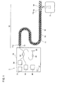
- FIG. 1 is a conceptual diagram of an OCT instrument 1 including an optical probe 10 according to an embodiment of the invention.
- the OCT instrument 1 includes the optical probe 10 and a measuring unit 30, and acquires an optical coherence tomographic image of an object 3.
- the optical probe 10 includes an optical fiber 11 that transmits light between a proximal end 11a and a distal end 11b, an optical connector 12 connected with the optical fiber 11 at a side of the proximal end 11 a, a focusing optical system 13 and a deflecting optical system 14 optically connected with the optical fiber 11 at a side of the distal end 11b, and a support tube 15 and a jacket tube 16 surrounding the optical fiber 11 and extending along the optical fiber 11.
- the optical connector 12 is optically connected with the measuring unit 30.
- the measuring unit 30 includes a light source 31 that emits near infrared light, a polarization adjusting part 38 that converts the near infrared light emitted from the light source 31 into near infrared light in a circular polarization state and outputs the near infrared light, an optical branching part 32 that branches the near infrared light output from the polarization adjusting part 38 into two of illumination light and reference light and outputs the illumination light and the reference light, an optical detector 33 that detects the light reaching from the optical branching part 32, an optical terminal 34 that outputs the reference light reaching from the optical branching part 32, a mirror 35 that reflects the reference light output from the optical terminal 34 to the optical terminal 34, an analyzing part 36 that analyzes a spectrum of the light detected by the optical detector 33, and an output port 37 that outputs the result of the analysis made by the analyzing part 36.
- the light source 31 outputs the near infrared light in a linear polarization state
- the polarization adjusting part 38 converts the near infrared light into the near infrared light in the circular polarization state.
- the near infrared light in the circular polarization state output from the polarization adjusting part 38 is branched into two of the illumination light and the reference light by the optical branching part 32, and output as the illumination light and the reference light.
- the illumination light output from the optical branching part 32 is incident on the proximal end 11a of the optical fiber 11 through the optical connector 12, guided by the optical fiber 11, emitted from the distal end 11b, and illuminated on the object 3 through the focusing optical system 13 and the deflecting optical system 14.
- the backward reflection light generated in accordance with the irradiation on the object 3 with the illumination light is incident on the distal end 11b of the optical fiber 11 through the deflecting optical system 14 and the focusing optical system 13. Then, the light is guided by the optical fiber 11, emitted from the proximal end 11 a, and coupled with the optical detector 33 through the optical connector 12 and the optical branching part 32.
- the reference light output from the optical branching part 32 is emitted from the optical terminal 34, is reflected by the mirror 35, passes through the optical terminal 34 and the optical branching part 32, and is coupled with the detector 33.
- the backward reflection light from the object 3 interferes with the reference light at the optical detector 33.
- the optical detector 33 detects the interference light.
- the spectrum of the interference light is input to the analyzing part 36.
- the analyzing part 36 analyzes the spectrum of the interference light, and hence calculates the distribution of backward reflection efficiency at respective points in the object 3.
- the tomographic image of the object 3 is calculated on the basis of the calculation result.
- the optical fiber 11, the focusing optical system 13, the deflecting optical system 14, and the support tube 15 of the optical probe 10 can rotate together in the jacket tube 15. With this rotation, the object 3 can be scanned with the illumination light.
- the tomographic image of the object 3 is calculated, and the tomographic image is output as an image signal from a signal output port 37.
- a mechanism in which the illumination light emitted from the distal end 11b of the optical fiber 11 reaches the object 3 and returns to the distal end 11b of the optical fiber 11 again, may include reflection, refraction, and scattering in strict sense.
- reflection, refraction, and scattering are not essential for the invention, and hence reflection, refraction, and scattering are collectively called backward reflection in the specification for simplifying the description.
- FIG. 2 is a conceptual diagram showing an inner structure of the optical probe 10 according to the embodiment.
- the optical fiber 11 is a typical single-mode optical fiber.
- the optical fiber has a structure in which a glass fiber 11c is covered with a resin coating 11d.
- the glass fiber 11c includes a core with high refractive index and a cladding with a low refractive index.
- the optical fiber 11 is fixed relative to the optical connector 12 at the side of the proximal end 11a, and is bonded and fixed to the support tube 15 through an adhesive 17 at the side of the distal end 11b.
- the optical fiber 11 is twisted, and has circular birefringence generated because the optical fiber 11 is twisted.
- the resin coating 11 d is removed from a fixed portion with respect to the optical connector 12 and a fixed portion with respect to the support tube 15.
- the optical connector 12 and the support tube 15 are fixed relative to the glass fiber 11c. Accordingly, when the optical connector 12 is rotated, a torque can be efficiently transmitted to the glass fiber 11c.
- a graded index (GRIN) lens serving as the focusing optical system 13, and a mirror serving as the deflecting optical system 14 are connected in series by fusion splicing at the distal end 11b of the optical fiber 11.
- the focusing optical system 13 focuses the light emitted from the distal end 11b of the optical fiber 11.
- the deflecting optical system 14 deflects the light emitted from the focusing optical system 13 in the radial direction.
- a GI lens with one end thereof being obliquely cut may form both the focusing optical system 23 and the deflecting optical system 24.
- the lens (the focusing optical system 13) and the mirror (the deflecting optical system 14) are formed of silica glass or borosilicate glass.
- the optical fiber 11 is housed in the inner cavity of the support tube 15.
- the support tube 15 is bonded and fixed to the optical fiber 11 at the side of the distal end 11b, and is fixed relative to the optical connector 12 at the side of the proximal end 11 a. Consequently, when the optical connector 12 is rotated, the support tube 15 is rotated together. Further, a rotation torque is transmitted to the optical fiber 11, and hence the optical fiber 11, the focusing optical system 13, the deflecting optical system 14, and the support tube 15 are rotated together.
- FIG 3 is a conceptual diagram of the support tube 15 in the optical probe 10 according to the embodiment.
- the support tube 15 is connected with the optical connector 12 at a side of a proximal end 15a, and is connected with the optical fiber 11 at a side of a distal end 15b.
- the support tube 15 has a structure in which a plurality of (typically, 5 to 50) metal wires 15c formed of stainless steel, a Co-Cr alloy, or a Ni-Ti alloy are stranded and twisted in a hollow shape.
- the support tube 15 has a thickness of 0.15 mm or larger, and a Young's modulus in a range from 100 to 300 GPa.
- the support tube 15 can have flexibility that allows the support tube 15 to be inserted into a soft and bent object, such as a blood vessel. At the same time, the support tube 15 can transmit a rotation torque applied to the side of the proximal end 11a efficiently to the side of the distal end 11b.
- a twist direction of the support tube 15 is defined by a rotation direction when the distal end 11b is viewed from the proximal end 11a and the viewpoint is moved toward the distal end 11b. Also, a rotation direction of the rotation applied to the optical fiber 11 at the proximal end 11a during use is defined by a rotation direction of the proximal end 11 a when the distal end 11b is viewed from the proximal end 11 a.
- the twist direction of the support tube 15 is a direction opposite to the rotation direction of the rotation applied to the optical fiber 11 at the proximal end 11a during use, that is, a direction in which the support tube 15 is twisted more strongly by the rotation.
- a force to move the proximal end 11 a clockwise relative to the distal end 11b is added.
- the distal end 11b is impeded from moving because of the inertia and friction. Accordingly, with this force, the proximal end 11a is twisted clockwise relative to the distal end 11b.
- the twist direction at this time is the counterclockwise direction. That is, when the support tube 15, which is twisted counterclockwise, is rotated clockwise, the support tube 15 is twisted more strongly. Accordingly, the support tube 15 can efficiently transmit the rotation torque.
- the support tube 15 is preferably formed by stranding metal wires in a form of a plurality of coaxial rings. Accordingly, torque transmitting performance of the support tube 15 can be further increased.
- the twist direction of the support tube 15 at the outermost-layer ring is preferably opposite to the direction of the rotation torque during use.
- the twist direction and the rotation direction during use of the optical fiber 11 are the clockwise direction (cw direction) (see Fig. 2 ), and the twist direction of the support tube is the counterclockwise direction (ccw direction) (see Fig. 3 ) that is opposite to the former direction. Accordingly, when the rotation torque is applied during use, the support tube 15 is further twisted counterclockwise by the rotation torque. The clockwise twist of the optical fiber 11 is restored once and then the optical fiber 11 is twisted counterclockwise.
- the counterclockwise twist of the optical fiber 11 is decreased by an amount by which the optical fiber 11 is originally twisted clockwise.
- the optical probe 10 is rotated at high speed, a large twist is added to the optical fiber 11 by the rotation torque, and hence there is a risk of fracture in which the optical fiber 11 may be broken by the large twist.
- the twist direction and the rotation direction of the optical fiber 11 may be the counterclockwise direction, and the twist direction of the support tube 15 may be the clockwise direction.
- both twist and bend are added to the optical fiber, both circular birefringence and linear birefringence are generated at the optical fiber. At this time, an effect of the larger birefringence becomes dominant.
- a bend added to the optical fiber may vary depending on the use state, by twisting the optical fiber beforehand to generate the larger birefringence than the linear birefringence caused by the bend, and by entering light in the circular polarization state to the optical fiber, the polarization state of light propagating through the optical fiber can be stably kept.
- Such a condition can be realized by applying a twist larger than a reference twist rate ⁇ 0 to the optical fiber.
- Figure 4 is a graph showing the relationship between a reference twist rate on the basis of the number of rotations, and a bend radius.
- the optical fiber 11 of the optical probe 10 may typically unavoidably have a bend radius larger than 50 mm, and may occasionally have a bend radius larger than 25 mm
- the reference twist rate corresponding to the bend radius of 50 mm is 1.1 turns/m
- the reference twist rate corresponding to the bend radius of 25 mm is 4.5 turns/m.
- the polarization state of the illumination light and the polarization state of the backward reflection light propagating through the optical fiber 11 can be stably kept.
- a twist of 5 turns/m or more to the optical fiber 11 the polarization state of the illumination light and the polarization state of the backward reflection light can be more likely stably kept.
- the twist rate of the optical fiber 11 is preferably 50 times per meter or smaller.
- the rotation speed is preferably increased.
- an additional twist is increased accordingly.
- the twist rate of the optical fiber 11 during rotation is preferably 50 turns/m or smaller.
- the twist rate of the optical fiber 11 is preferably 5 turns/m or larger. Also, even when only one portion of the object 3 is measured without rotation, to keep the polarization state of the illumination light and the polarization state of the backward reflection light constant, a twist of one turn/m or more is preferably applied to the optical fiber 11 beforehand.
Landscapes
- Health & Medical Sciences (AREA)
- Life Sciences & Earth Sciences (AREA)
- Physics & Mathematics (AREA)
- General Health & Medical Sciences (AREA)
- General Physics & Mathematics (AREA)
- Engineering & Computer Science (AREA)
- Heart & Thoracic Surgery (AREA)
- Veterinary Medicine (AREA)
- Biophysics (AREA)
- Pathology (AREA)
- Public Health (AREA)
- Biomedical Technology (AREA)
- Animal Behavior & Ethology (AREA)
- Medical Informatics (AREA)
- Molecular Biology (AREA)
- Surgery (AREA)
- Nuclear Medicine, Radiotherapy & Molecular Imaging (AREA)
- Radiology & Medical Imaging (AREA)
- Optics & Photonics (AREA)
- Spectroscopy & Molecular Physics (AREA)
- Investigating Or Analysing Materials By Optical Means (AREA)
Applications Claiming Priority (2)
| Application Number | Priority Date | Filing Date | Title |
|---|---|---|---|
| JP2012063984A JP5655805B2 (ja) | 2012-03-21 | 2012-03-21 | 光プローブおよび光学的測定方法 |
| PCT/JP2013/057139 WO2013141128A1 (ja) | 2012-03-21 | 2013-03-14 | 光プローブおよび光学的測定方法 |
Publications (2)
| Publication Number | Publication Date |
|---|---|
| EP2829863A1 true EP2829863A1 (de) | 2015-01-28 |
| EP2829863A4 EP2829863A4 (de) | 2015-11-11 |
Family
ID=49222587
Family Applications (1)
| Application Number | Title | Priority Date | Filing Date |
|---|---|---|---|
| EP13763662.7A Withdrawn EP2829863A4 (de) | 2012-03-21 | 2013-03-14 | Optische sonde und optisches messverfahren |
Country Status (5)
| Country | Link |
|---|---|
| US (1) | US9128249B2 (de) |
| EP (1) | EP2829863A4 (de) |
| JP (1) | JP5655805B2 (de) |
| CN (1) | CN103703355A (de) |
| WO (1) | WO2013141128A1 (de) |
Families Citing this family (5)
| Publication number | Priority date | Publication date | Assignee | Title |
|---|---|---|---|---|
| JP5668708B2 (ja) * | 2012-02-14 | 2015-02-12 | 住友電気工業株式会社 | 光プローブ |
| JP5983676B2 (ja) * | 2014-05-16 | 2016-09-06 | 住友電気工業株式会社 | 光プローブ |
| JP6157787B1 (ja) * | 2015-11-17 | 2017-07-05 | オリンパス株式会社 | 内視鏡 |
| US10041163B1 (en) | 2017-02-03 | 2018-08-07 | Ge-Hitachi Nuclear Energy Americas Llc | Plasma spray coating for sealing a defect area in a workpiece |
| US10802225B2 (en) * | 2018-01-08 | 2020-10-13 | 3M Innovative Properties Company | Inspection device for optical connector |
Family Cites Families (19)
| Publication number | Priority date | Publication date | Assignee | Title |
|---|---|---|---|---|
| DE3483464D1 (de) * | 1983-12-19 | 1990-11-29 | Raychem Sa Nv | Abzweigung fuer optische fasern. |
| US5452394A (en) * | 1994-02-24 | 1995-09-19 | Huang; Hung-Chia | Practical circular-polarization maintaining optical fiber |
| US5740295A (en) * | 1994-11-02 | 1998-04-14 | Lucent Technologies Inc. | Low fiber count optical cable |
| US6615072B1 (en) * | 1999-02-04 | 2003-09-02 | Olympus Optical Co., Ltd. | Optical imaging device |
| US6445939B1 (en) | 1999-08-09 | 2002-09-03 | Lightlab Imaging, Llc | Ultra-small optical probes, imaging optics, and methods for using same |
| JP2002263106A (ja) * | 2001-03-12 | 2002-09-17 | Olympus Optical Co Ltd | 光プローブ装置 |
| US6881194B2 (en) * | 2001-03-21 | 2005-04-19 | Asahi Intec Co., Ltd. | Wire-stranded medical hollow tube, and a medical guide wire |
| EP2290319B1 (de) * | 2002-01-11 | 2015-08-26 | The General Hospital Corporation | OCT Einrichtung mit axialem Linienfokus für verbesserte Auflösung und Tiefenschärfe |
| US6891984B2 (en) * | 2002-07-25 | 2005-05-10 | Lightlab Imaging, Llc | Scanning miniature optical probes with optical distortion correction and rotational control |
| US7167622B2 (en) * | 2004-04-08 | 2007-01-23 | Omniguide, Inc. | Photonic crystal fibers and medical systems including photonic crystal fibers |
| US7317855B2 (en) * | 2004-12-16 | 2008-01-08 | Corning Incorporated | Method of imparting twist to optical fiber |
| JP4160603B2 (ja) * | 2006-03-13 | 2008-10-01 | オリンパス株式会社 | 光イメージング装置 |
| JP2008142443A (ja) * | 2006-12-13 | 2008-06-26 | Fujifilm Corp | 光断層画像化装置 |
| JP4930107B2 (ja) * | 2007-03-06 | 2012-05-16 | 住友電気工業株式会社 | 光ファイバのpmd特性測定方法、線引方法、異常個所特定方法、光ファイバ伝送路構築方法 |
| CN201019719Y (zh) * | 2007-03-29 | 2008-02-13 | 浙江大学 | 用于在体光学活检的谱域oct内窥成像装置 |
| WO2009137704A1 (en) * | 2008-05-07 | 2009-11-12 | Volcano Corporation | Optical imaging catheter for aberration balancing |
| US8314391B2 (en) * | 2007-12-31 | 2012-11-20 | Honeywell Asca Inc. | Controlling the bends in a fiber optic cable to eliminate measurement error in a scanning terahertz sensor |
| US8564783B2 (en) * | 2008-05-15 | 2013-10-22 | Axsun Technologies, Inc. | Optical coherence tomography laser with integrated clock |
| US9138948B2 (en) * | 2008-09-10 | 2015-09-22 | Kyton, Llc | Suspended and compact fiber optic sensors |
-
2012
- 2012-03-21 JP JP2012063984A patent/JP5655805B2/ja not_active Expired - Fee Related
-
2013
- 2013-03-14 EP EP13763662.7A patent/EP2829863A4/de not_active Withdrawn
- 2013-03-14 WO PCT/JP2013/057139 patent/WO2013141128A1/ja not_active Ceased
- 2013-03-14 US US14/234,040 patent/US9128249B2/en not_active Expired - Fee Related
- 2013-03-14 CN CN201380002324.2A patent/CN103703355A/zh active Pending
Also Published As
| Publication number | Publication date |
|---|---|
| US9128249B2 (en) | 2015-09-08 |
| US20140158888A1 (en) | 2014-06-12 |
| JP2013195284A (ja) | 2013-09-30 |
| EP2829863A4 (de) | 2015-11-11 |
| CN103703355A (zh) | 2014-04-02 |
| JP5655805B2 (ja) | 2015-01-21 |
| WO2013141128A1 (ja) | 2013-09-26 |
Similar Documents
| Publication | Publication Date | Title |
|---|---|---|
| EP1526800B1 (de) | Scannende optische miniatursonde mit korrektur der optischen fehler und kontrolle der rotationsbewegung | |
| JP5136747B2 (ja) | 曲がり度合い検出装置およびそれを用いた曲がり度合い検出方法 | |
| US9864140B2 (en) | Miniature optical elements for fiber-optic beam shaping | |
| EP1804638B1 (de) | System und verfahren zur abbildung optischer kohärenz | |
| US20180177404A1 (en) | Gradient Index Lens Assembly-Based Imaging Apparatus, Systems and Methods | |
| US10816789B2 (en) | Optical probes that include optical-correction components for astigmatism correction | |
| US9645322B2 (en) | Optical probe for optical coherence tomography and manufacturing method therefor | |
| US10806329B2 (en) | Optical probes with optical-correction components | |
| US9128249B2 (en) | Optical probe and optical measuring method | |
| EP2706388A1 (de) | Optische sonde | |
| EP2803973A1 (de) | Optische sonde und optisches messverfahren | |
| US9453966B2 (en) | Optical probe | |
| US10401140B2 (en) | Bending detecting system, light guide body, tubular apparatus, light detecting apparatus, light detecting method, and optical bending measuring apparatus | |
| WO2015025932A1 (ja) | 光プローブおよび光学的測定方法 | |
| JP2014094121A (ja) | 光伝達装置及び光学素子 | |
| JP2016202281A (ja) | 光プローブ | |
| JP2014094123A (ja) | 光伝達装置及び光学素子 | |
| JP2021536591A (ja) | 光学形状感知及びスペクトル組織感知のための統合型ファイバ | |
| Luo et al. | Coupling and cross-talk effects in 12–15 μm diameter single-mode fiber arrays for simultaneous transmission and photon collection from scattering media |
Legal Events
| Date | Code | Title | Description |
|---|---|---|---|
| PUAI | Public reference made under article 153(3) epc to a published international application that has entered the european phase |
Free format text: ORIGINAL CODE: 0009012 |
|
| 17P | Request for examination filed |
Effective date: 20140114 |
|
| AK | Designated contracting states |
Kind code of ref document: A1 Designated state(s): AL AT BE BG CH CY CZ DE DK EE ES FI FR GB GR HR HU IE IS IT LI LT LU LV MC MK MT NL NO PL PT RO RS SE SI SK SM TR |
|
| AX | Request for extension of the european patent |
Extension state: BA ME |
|
| DAX | Request for extension of the european patent (deleted) | ||
| RIN1 | Information on inventor provided before grant (corrected) |
Inventor name: HIRANO, MITSUHARU Inventor name: HASEGAWA, TAKEMI |
|
| STAA | Information on the status of an ep patent application or granted ep patent |
Free format text: STATUS: THE APPLICATION HAS BEEN WITHDRAWN |
|
| RA4 | Supplementary search report drawn up and despatched (corrected) |
Effective date: 20151013 |
|
| RIC1 | Information provided on ipc code assigned before grant |
Ipc: G02B 6/00 20060101ALN20151007BHEP Ipc: G02B 6/35 20060101ALI20151007BHEP Ipc: G01N 21/17 20060101AFI20151007BHEP Ipc: A61B 5/00 20060101ALI20151007BHEP Ipc: G02B 6/10 20060101ALI20151007BHEP |
|
| 18W | Application withdrawn |
Effective date: 20151021 |