EP2829696B1 - Verfahren zur Überwachung der Leistung des Schmiermittelkühlers in einer Flugzeughilfsturbineneinheit - Google Patents
Verfahren zur Überwachung der Leistung des Schmiermittelkühlers in einer Flugzeughilfsturbineneinheit Download PDFInfo
- Publication number
- EP2829696B1 EP2829696B1 EP14178342.3A EP14178342A EP2829696B1 EP 2829696 B1 EP2829696 B1 EP 2829696B1 EP 14178342 A EP14178342 A EP 14178342A EP 2829696 B1 EP2829696 B1 EP 2829696B1
- Authority
- EP
- European Patent Office
- Prior art keywords
- apu
- lubricant
- temperature
- revised
- cooler
- Prior art date
- Legal status (The legal status is an assumption and is not a legal conclusion. Google has not performed a legal analysis and makes no representation as to the accuracy of the status listed.)
- Active
Links
Images


Classifications
-
- F—MECHANICAL ENGINEERING; LIGHTING; HEATING; WEAPONS; BLASTING
- F02—COMBUSTION ENGINES; HOT-GAS OR COMBUSTION-PRODUCT ENGINE PLANTS
- F02C—GAS-TURBINE PLANTS; AIR INTAKES FOR JET-PROPULSION PLANTS; CONTROLLING FUEL SUPPLY IN AIR-BREATHING JET-PROPULSION PLANTS
- F02C7/00—Features, components parts, details or accessories, not provided for in, or of interest apart form groups F02C1/00 - F02C6/00; Air intakes for jet-propulsion plants
- F02C7/12—Cooling of plants
- F02C7/14—Cooling of plants of fluids in the plant, e.g. lubricant or fuel
-
- B—PERFORMING OPERATIONS; TRANSPORTING
- B64—AIRCRAFT; AVIATION; COSMONAUTICS
- B64D—EQUIPMENT FOR FITTING IN OR TO AIRCRAFT; FLIGHT SUITS; PARACHUTES; ARRANGEMENT OR MOUNTING OF POWER PLANTS OR PROPULSION TRANSMISSIONS IN AIRCRAFT
- B64D33/00—Arrangement in aircraft of power plant parts or auxiliaries not otherwise provided for
- B64D33/08—Arrangement in aircraft of power plant parts or auxiliaries not otherwise provided for of power plant cooling systems
-
- F—MECHANICAL ENGINEERING; LIGHTING; HEATING; WEAPONS; BLASTING
- F01—MACHINES OR ENGINES IN GENERAL; ENGINE PLANTS IN GENERAL; STEAM ENGINES
- F01M—LUBRICATING OF MACHINES OR ENGINES IN GENERAL; LUBRICATING INTERNAL COMBUSTION ENGINES; CRANKCASE VENTILATING
- F01M5/00—Heating, cooling, or controlling temperature of lubricant; Lubrication means facilitating engine starting
- F01M5/002—Cooling
-
- G—PHYSICS
- G01—MEASURING; TESTING
- G01M—TESTING STATIC OR DYNAMIC BALANCE OF MACHINES OR STRUCTURES; TESTING OF STRUCTURES OR APPARATUS, NOT OTHERWISE PROVIDED FOR
- G01M15/00—Testing of engines
- G01M15/14—Testing gas-turbine engines or jet-propulsion engines
-
- B—PERFORMING OPERATIONS; TRANSPORTING
- B64—AIRCRAFT; AVIATION; COSMONAUTICS
- B64D—EQUIPMENT FOR FITTING IN OR TO AIRCRAFT; FLIGHT SUITS; PARACHUTES; ARRANGEMENT OR MOUNTING OF POWER PLANTS OR PROPULSION TRANSMISSIONS IN AIRCRAFT
- B64D41/00—Power installations for auxiliary purposes
-
- F—MECHANICAL ENGINEERING; LIGHTING; HEATING; WEAPONS; BLASTING
- F01—MACHINES OR ENGINES IN GENERAL; ENGINE PLANTS IN GENERAL; STEAM ENGINES
- F01M—LUBRICATING OF MACHINES OR ENGINES IN GENERAL; LUBRICATING INTERNAL COMBUSTION ENGINES; CRANKCASE VENTILATING
- F01M11/00—Component parts, details or accessories, not provided for in, or of interest apart from, groups F01M1/00 - F01M9/00
- F01M11/10—Indicating devices; Other safety devices
-
- F—MECHANICAL ENGINEERING; LIGHTING; HEATING; WEAPONS; BLASTING
- F05—INDEXING SCHEMES RELATING TO ENGINES OR PUMPS IN VARIOUS SUBCLASSES OF CLASSES F01-F04
- F05D—INDEXING SCHEME FOR ASPECTS RELATING TO NON-POSITIVE-DISPLACEMENT MACHINES OR ENGINES, GAS-TURBINES OR JET-PROPULSION PLANTS
- F05D2220/00—Application
- F05D2220/50—Application for auxiliary power units (APU's)
-
- F—MECHANICAL ENGINEERING; LIGHTING; HEATING; WEAPONS; BLASTING
- F05—INDEXING SCHEMES RELATING TO ENGINES OR PUMPS IN VARIOUS SUBCLASSES OF CLASSES F01-F04
- F05D—INDEXING SCHEME FOR ASPECTS RELATING TO NON-POSITIVE-DISPLACEMENT MACHINES OR ENGINES, GAS-TURBINES OR JET-PROPULSION PLANTS
- F05D2260/00—Function
- F05D2260/80—Diagnostics
-
- F—MECHANICAL ENGINEERING; LIGHTING; HEATING; WEAPONS; BLASTING
- F05—INDEXING SCHEMES RELATING TO ENGINES OR PUMPS IN VARIOUS SUBCLASSES OF CLASSES F01-F04
- F05D—INDEXING SCHEME FOR ASPECTS RELATING TO NON-POSITIVE-DISPLACEMENT MACHINES OR ENGINES, GAS-TURBINES OR JET-PROPULSION PLANTS
- F05D2260/00—Function
- F05D2260/98—Lubrication
-
- Y—GENERAL TAGGING OF NEW TECHNOLOGICAL DEVELOPMENTS; GENERAL TAGGING OF CROSS-SECTIONAL TECHNOLOGIES SPANNING OVER SEVERAL SECTIONS OF THE IPC; TECHNICAL SUBJECTS COVERED BY FORMER USPC CROSS-REFERENCE ART COLLECTIONS [XRACs] AND DIGESTS
- Y02—TECHNOLOGIES OR APPLICATIONS FOR MITIGATION OR ADAPTATION AGAINST CLIMATE CHANGE
- Y02T—CLIMATE CHANGE MITIGATION TECHNOLOGIES RELATED TO TRANSPORTATION
- Y02T50/00—Aeronautics or air transport
- Y02T50/60—Efficient propulsion technologies, e.g. for aircraft
Definitions
- the present invention relates to a method for monitoring performance of an aircraft component, in particular to a method for monitoring performance of the lubricant cooler in the aircraft auxiliary power unit.
- Auxiliary Power Unit is a small turbine engine mounted on the tail of an aircraft. Its main function is to supply power and a gas source, and some APUs are capable of providing additive thrust to the aircraft. Specifically, before taking off from the ground, an aircraft may rely on power and gas supply from the APU to start the main engine, rather than the ground power and gas source vehicles. While on the ground, the APU also supplies power and compressed air to ensure lighting and air-conditioning in the cabin and cockpit. During take-off of an aircraft, the APU can serve as a backup power source. After the aircraft is landed, lighting and air-conditioning of the aircraft are still maintained by power from the APU. The functions of APU influences the flight stability of the aircraft, which directly affects flight cost and quality of service of the aircraft.
- US 2012 0 312 023 A1 discloses thermo management systems and methods for auxiliary power units. Therein, the airflow to an oil cooler is adjusted by controlling the position of an inlet door of an air intake duct. The position of the inlet door is controlled according to the temperature of the APU.
- APU lubricant cooler is an important component in APU, and the operation of APU is directly impacted by the performance of the lubricant cooler. Poor operation of lubricant cooler is likely to result in shut-down of APU, or even grounding of the aircraft. Once grounding occurs, the cost for consequent maintenance and repair is very expensive.
- One is weekly inspection, that is, measuring and calculating the temperature of the lubricant weekly, and checking whether the temperature exceeds the limit.
- uninspected case of exceed the temperature limit may happen, and thus the shut-down of APU cannot be avoided absolutely.
- the other is periodical inspection of lubricant cooler according to the reliable statistical data. Although the latter can effectively avoid the shut-down of APU caused by the performance degradation of the lubricant cooler, replacement or repair in fixed period cost more air materials, and hence it is not beneficial for reducing the maintenance cost.
- decline phase or malfunction phase comprises: response to the change trend is less than the threshold value of decline, determining the performance of the APU lubricant cooler is in stable phase; response to the change trend is greater than the threshold value of decline and less than the threshold value of malfunction, determining the performance of the APU lubricant cooler is in decline phase; and response to the change trend is greater than the threshold value of malfunction, determining the performance of the APU lubricant cooler is in malfunction phase.
- the method described above further comprises: determining the stable change trend of the revised lubricant temperature OT with respect to time when the APU lubricant cooler is in stable phase; wherein, the threshold value of the decline phase is around 1.5-2.5 times than the stable change trend, and the threshold value of malfunction is around 5-7 times than the stable change trend.
- the decline phase further comprises serious decline phase
- the threshold value of serious decline is between the threshold values of the decline and malfunction
- response to the change trend is greater than the threshold value of the serious decline and less than the threshold value of malfunction
- determining the performance of the APU lubricant cooler is in serious decline phase wherein the method further comprises: determining the stable change trend of the revised lubricant temperature OT with respect to time when the APU oil lube cooler is in stable phase; wherein, the threshold value of the serious decline is around 2.5-5 times than the stable change trend.
- the method described above further comprises: the time is time since installation TSR of APU.
- the method described above further comprises: response to the lubricant temperature OTA exceeding the first threshold, inputting the warning signal.
- the method described above further comprises: response to the revised lubricant temperature OT exceeding the second threshold, inputting the warning signal.
- the method described above further comprises: calculating the average value AVG and the deviation index ⁇ of the revised lubricant temperature OT within the time period; determining the revised lubricant temperature OT next obtained according to the next message related to APU; and response to OT next is greater than AVG+n ⁇ or less than AVG-n ⁇ , determining whether the revised lubricant temperature OT nexi+1 obtained according to the further next message related to APU is equally greater than AVG+n ⁇ or less than AVG-n ⁇ ; response to the revised lubricant temperature obtained according to the message related to APU is equally greater than AVG+n ⁇ or less than AVG-n ⁇ continuously and exceeding the predetermined number Z, inputting the warning; wherein n is 2-5, and Z is 3-5.
- response to the revised lubricant temperature obtained according to the message related to APU is greater than AVG+n ⁇ or less than AVG-n ⁇ , recalculating the average value AVG and deviation index ⁇ of the revised lubricant temperature OT .
- response to the revised lubricant temperature obtained according to the message related to APU is equally greater than AVG+n ⁇ or less than AVG-n ⁇ continuously and exceeding the predetermined number Z, recalculating the average value AVG and deviation index ⁇ of the revised lubricant temperature OT.
- the method described above further comprises that: response to the revised lubricant temperature obtained according to the message related to APU is greater than AVG+n ⁇ continuously and exceeding the predetermined number Z, inputting the warning of lubricant cooler.
- the method described above further comprises that: response to the revised lubricant temperature obtained according to the message related to APU is greater than AVG-n ⁇ continuously and exceeding the predetermined number Z, inputting the warning of sensor.
- the method described above further comprises that: estimating the time when the lubricant sensor encounter a malfunction.
- TSR time since installation
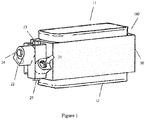
- Fig.1 is a schematic drawing illustrating the structure of lubricant cooler of the aircraft APU according to one embodiment of the present invention.
- Fig.2 is a schematic drawing illustrating internal structure of the lubricant cooler and its operation principle.
- lubricant cooler 100 comprises lubricant cooler housing body 10 and lubricant channel component 20.
- the lubricant cooler housing body 10 has a cooling air inlet 11 and a cooling air outlet 12.
- the lubricant channel component 20 comprises lubricant inlet 20, lubricant outlet 22, bypass valve 23, inspection valve 24, drain plug 25 and heat dissipating oil channel 26.
- the cooling air enters into the housing body 10 through the cooling air inlet 11, and comes into atmosphere through cooling air outlet 12 after passing through the heat dissipating oil channel 26 inside the housing body 10.
- the high-temperature lubricant enters into the heat dissipating oil channel 26 inside the housing body 10 through the lubricant inlet 21 under the drive of the lubricant pump. Since the temperature of the lubricant is higher than that of the cooling air, heat exchange occurs inside the housing body 10, and thus the lubricant temperature is lowered.
- lubricant may not go through the radiating oil channel 26.
- the lubricant temperature can be raised quickly, and thus it can be applied at the time of starting to raise the APU temperature quickly, in order to make APU come into its best working status as soon as possible.
- APU lubricant cooler In order to realize the detection of the performance of the APU lubricant cooler, it is needed to monitor the operation state of the lubricant cooler and acquire the real-time relevant data in the operation of the lubricant cooler.
- the acquisition of such data is usually realized by the data systems provided by the aircraft manufacturer.
- ACMS Aircraft Condition Monitoring System
- AHM Aircraft Heath Monitor
- One character of these systems is that the operation data of the aircraft can be monitored instantly. Meanwhile, when certain trigger conditions are met, the message comprising a series of data information will be generated automatically.
- the decline data of the performance of the APU lubricant cooler can thus be obtained.
- the reliability of the APU lubricant cooler can thus be evaluated.
- the relevant operation data of APU can be obtained by the aircraft data system (such as ACMS or AHM system) and reflected in the generated relevant messages.
- This kind of message information can be transferred to the ground by Aircraft Communications Addressing and Reporting System (ACARS), and further distributed to the servers of different airlines.
- ACARS Aircraft Communications Addressing and Reporting System
- APU message can also be transferred by the communicating device or system of Aviation Telecommunication Network (ATN).
- ATN Aviation Telecommunication Network
- the monitoring of the performance of APU is existing. Therefore, the corresponding APU messages can be used, and transferred to the ground by ACARS or ATN.
- the A13 message of Airbus i.e. APU MES/IDLE REPORT, or the APU message of Boeing are just the cases.
- these monitored data have not been used for the detection of the decline phase of the performance of APU lubricant cooler.
- the method for monitoring the performance of lubricant cooler according to the APU message is illustrated by taking the A13 message of Airbus as an example.
- the treatment of APU message of Boeing is similar to this method.
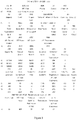
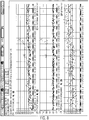
- FIG. 3 shows an example of A13 message of Airbus.
- A13 message mainly comprises 4 parts of information, which are: the message heading, APU record information, the operation parameters in starting of the aircraft engine and the start parameter of APU.
- the message heading is consisted of CC and C1 fields, and mainly includes the flight information of the aircraft, the segment wherein the message generated, the state of bleed valves, total air temperature (i.e. the outer temperature) and the like information.
- the APU record information is consisted of E1 field, comprising APU serial number, operation time and cycle and other information.
- the operation parameters in starting of the aircraft engine is consisted of N1 to S3 fields; wherein N1 and S1 represent the operation on the time of starting the first aircraft engine, N2 and S2 represent the operation on the time of starting the second aircraft engine, and N3 and S3 represent the slow-down state of APU after completing the starting of engine by APU.
- A13 message comprises multiple parameters relevant to the operation of APU.
- the operation of lubricant cooler is mainly characterized by a particular lubricant temperature (OTA) of the time since installation (TSR) of APU and load compressor inlet temperature (LCIT).
- OTA lubricant temperature
- TSR time since installation
- LCIT load compressor inlet temperature
- the lubricant cooler cools the lubricant through introducing the cooling air, and thus the temperature of lubricant is greatly influenced by the outer temperature. Therefore, the directly measured data of lubricant temperature (OTA) cannot objectively characterize the operation of lubricant cooler, and needs to be revised by the outer temperature.
- OTA directly measured data of lubricant temperature
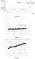
- Figs 4a-c illustrate the revise course of the lubricant temperature according to one example of the invention, wherein, Fig. 4a shows the lubricant temperature OTA before revising; Fig. 4b shows the load compressor inlet temperature LCIT representing the outer temperature; Fig. 4c shows the revised lubricant temperature OT.
- the change of the lubricant temperature OTA before revising is irregular. From Fig. 4b , it can be seen that the change trend of the load compressor inlet temperature LCIT is almost the same as the change trend of the lubricant temperature OTA before revision. Referring to Fig. 4c , the revised lubricant temperature OT presents a particular slow a regular pattern of slow change which reflects the change of performance of the lubricant cooler.
- the change of the performance of the lubricant cooler is abide by certain rules: the performance of the lubricant cooler is relatively stable in the early and middle phases in use, and becomes declined in the late phase, finally a failure occurs.
- the performance of the APU lubricant cooler declines gradually, and the temperature of lubricant shows a trend of increase, the decline index increases gradually.
- the decline index of the performance of the APU lubricant cooler is relatively stable, the performance is in stable phase; when the decline of the performance of the APU lubricant cooler becomes faster gradually, the performance comes into decline phase; when exceeding some threshold value, the performance comes into malfunction phase, and a failure may occur at any time.
- the detection of decline phase has the following benefits: first, when APU lubricant cooler is in decline phase, the probability of the occurrence of a failure is still very low. If the maintenance/repair is proceeded on the aircraft at this time, the flying safety and quality of service can be guaranteed; second, when detecting that the APU lubricant cooler is in decline phase, the airline can arrange the maintenance/repair of the aircraft timely, and thus the non-planned maintenance can be avoided, the flight delay can be reduced accordingly, and therefore a waste of the cost for maintenance/repair resulted from the inspection in fixed period can be avoided at the same time.
- the example of the invention can also be applied for the inspection in malfunction phase.
- Fig. 5a is the schematic drawing showing a curve of the change of performance of the APU lubricant cooler. According to the change regulation of the performance of the APU lubricant cooler shown in Fig. 5a , through the statistical analysis of the lubricant temperature within a particular time range, judging the change trend of the lubricant temperature in the lubricant cooler, the detection of the performance of the APU lubricant cooler can be realized.
- Fig 5b shows an example of the statistical trend of the performance data in early phase of operation, and
- Fig 5c shows an example of the statistical trend of the performance data in late phase of operation.
- the slope reflecting the change trend is 0.0048.
- the slope reflecting the change trend is 0.0293, near 0.03. The change of slope fully reflect the different phases of the performance of the APU lubricant cooler.
- Fig 5d shows an example of the statistical trend of the long-term performance data of the lubricant cooler.
- the upper part of the figure is the change trend of the lubricant temperature OTA; the lower part of the figure is the change trend of the compressor inlet temperature; and the middle part is the change trend of the revised lubricant temperature OT.
- the vertical solid line represents the replacement of the lubricant cooler.
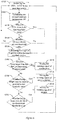
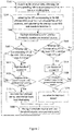
- Fig.6 is a flow diagram showing the of the detection method of the performance of the APU lubricant cooler according to one embodiment of the present invention.
- the detection method 6000 for the performance of the APU lubricant cooler in the detection method 6000 for the performance of the APU lubricant cooler, in the step 6100, the following operation information of the APU of aircraft within a time period is acquired through APU messages,: the time since installation (TSR) of APU, the load compressor inlet temperature (LCIT) and lubricant temperature OTA.
- TSR time since installation
- LCIT load compressor inlet temperature
- OTA lubricant temperature OTA
- the lubricant temperature OTA is revised by the load compressor inlet temperature (LCIT), and the revised lubricant temperature OT within a time period can be obtained.
- the detected lubricant temperature OTA is compared with the first threshold, if exceeding the first threshold, a warning signal of overheating of the lubricant is output.
- the revised lubricant temperature OT is compared with the second threshold, if exceeding the second threshold, a warning signal of serious overheating of the lubricant is output.
- the first and second thresholds are determined by the design of APU. The aircraft APU of different models have different threshold values. Generally, the first threshold value is 5-10 degrees Celsius below the red line value.
- the second threshold value can be determined according to the first threshold value and the influence of the outer air temperature on the temperature of the inlet of the load compressor. Generally, the second threshold value is 30-50 Celsius degrees below the first threshold value, preferably 40 degrees Celsius.
- the first threshold is 135°C
- the second threshold is 95°C
- the model of APU is 131-9A
- the first threshold is 162.78°C
- the second threshold is 122.78°C.
- calculating the linear-fitting slope reflecting the change of the temperature of the lubricant within a time range in order to judge the performance of the performance of the APU lubricant cooler.
- a time scrolled window comprises M time points, in the step 6500, taking the time since installation (TSR) of APU as horizontal axis, and the revised lubricant temperature OT as vertical axis, calculating the slope of the M points within the time scrolled window.
- the size of scrolled window i.e. the number M of points included within the range of calculation, depends on multiple factors, such as, the time interval of measurement, the control strategy and others. In case the size is too small, the change of slope is more easily influenced by the normal fluctuation of the lubricant temperature, and more error alarms/messages will be generated, the effect of the invention will be affected finally.
- the size of the scrolled window is important to the present invention.
- the value of M is about 20 in case of measuring 2-3 points daily.
- the value of M is about 10 in case of measuring no more than 2 point(s) daily.
- the value of M is about 30 in case of measuring 4-5 points daily.
- the APU operation data can be obtained via the output APU messages when the aircraft is in operation.
- the desired APU operation data can be obtained by triggering the logic in the customized messages automatically programmed in ACMS and acquiring the messages comprising the desired data.
- the logic can be triggered by programming the customized messages, and obtaining the APU operation data at the time point when APU load reaches the peak value.
- the logic can be triggered by programming the customized messages, and obtaining the APU operation data at the time point when APU load is identical (i.e., the APU load is a set value).
- the step of discarding the bad points is also included before calculating the slope of the linear-fitting plot of the lubricant temperature within the scrolled window.
- the difference between the value of one point and the average value of the closest p points is more than q times of the standard deviation of the closest p points, this point will not participate the calculation of the slope in the scrolled window, and wherein, in some examples, the value of p can be 4, 6 or 8; and the value of q is 2 or 3.
- step 6600 comparing whether the slope of the closest M points obtained in the last step exceeds the failure threshold value. If the slope exceeds failure value, the failure warning of the APU lubricant cooler is output in step 6610.
- step 6700 comparing whether the slope of the closest M points obtained in the last step exceeds the threshold value of serious decline. If the slope exceeds the threshold value of serious decline, the warning of serious decline of the APU lubricant cooler is output in step 6710.
- step 6800 comparing whether the slope of the closest M points obtained in the last step exceeds the decline threshold value. If the slope exceeds the decline threshold value, the decline warning of the APU lubricant cooler is output in step 6810.
- the step 6100 will be repeated regardless of whether the warning signal is output or not, and entering the next cycle.
- the decline threshold value is 1.5-2.5 times than the change trend of the stable phase
- the threshold value of the serious decline is 2.5-5 times than the change trend of the stable phase
- the failure threshold value is 5-7 times than the change trend of the stable phase.
- the performance of the APU lubricant cooler entering the decline phase can only be confirmed when the decline warning is repeated 5 times continuously or in short time period; only if serious decline warning is repeated 3 times continuously or in short time period, it is can be confirmed that the performance of the APU lubricant cooler enters the serious decline phase; and only if failure warning is repeated 2 times continuously or in short time period, it is can be confirmed that the performance of the APU lubricant cooler enters the malfunction phase.
- the desired information in step 6100 can be obtained from the APU message of the A13 message.
- the control centre of Society International De Telecommunication Aeronautiques (SITA) and the control centre of Aviation Data Communication Corporation (ADCC) can obtain the A13 message of the operation of the APU remotely in real-time, and decode the A13 message of the APU operation modes by message decoder, and achieve the desired operation information of the APU lubricant cooler.
- SITA Society International De Telecommunication Aeronautiques
- ADCC control centre of Aviation Data Communication Corporation
- APU operation message is not generated automatically in the aircraft data system, adding the corresponding sensor and trigger condition to generate the desired APU message. If the APU message already existed in the aircraft data system does not completely cover one or more of the desired lubricant OTA and load compressor inlet temperature LCIT, adding one or more missed measurement parameters by revising the generating conditions of APU message. Since APU message can be transferred to the data server of the airlines in real time through ACARS or ATN systems, the real time monitoring of the performance of APU can be realized. Of course, the mode of message transfer can avoid the high cost and human failure caused by manual mode.
- the desired information in step 6100 can be directly obtained through the aircraft data system, and no APU message is needed to be generated.
- the above-mentioned method monitors the change trend of data of the operation state in a period of time when APU lubricant cooler is in operation.
- some cases of poor operation of a sharp rise or fall in temperature in short time are also existed.
- the main cause for such case is the sudden failure of the lubricant cooler or sensor malfunction.
- the method for monitoring the performance of APU lubricant cooler further comprises monitoring the sudden change of its performance.
- Fig.7 is a flow diagram showing the detection method of the performance of the APU lubricant cooler according to another example of the invention.
- the actual lubricant temperature OT is obtained by acquiring the relevant operation data of aircraft APU lubricant cooler, such as the testing lubricant temperature OTA, the load compressor inlet temperature LCIT, within a working time period and subsequent revise.
- this step can be performed in the way similar to above-mentioned steps 6100 and 6200.
- step 7200 obtaining the revised lubricant temperature OT corresponding to M data points wherein M is equal to a sum of capacities of high threshold counter and low threshold counter, and calculating the average value AVG and standard deviation ⁇ .
- the purpose for evaluating the average value and standard deviation of a designated number of points is to set a range of change for the next point, but the value which may be noise needs to be removed.
- high threshold counter and low threshold counter are used for recording the deviation point which changes beyond the preset range.
- the pointer which is used to acquire the numerical value needs to be moved forward a number of points, wherein the number is the sum of the two counters, that is, taking the revised lubricant temperature OT corresponding to M data points in the front of the data points by the addition of high threshold counter and low threshold counter.
- the value of M can be 20.
- step 7300 the high threshold counter and low threshold counter are reverted to zero, because that: as a result of the previous judgment, the deviation points are dispersed.
- the counter needs to be reverted to zero and recount. Counter of this mode can be realized by various ways.
- step 7400 judging whether the revised lubricant temperature OT corresponding to the next data point is greater than AVG+n ⁇ .
- the value of n is determined by control strategy. If the value of n is high, the control of abnormal point is loose, and consequently the number of error messages can be reduced this way, but the risk of failing to inform may exist; if the value of n is low, the control of abnormal points is stricter, and the risk of failure can be avoided, but too frequent useless warning will occur.
- the value of n is between 1-5. According to one example of the invention, the value of n is 2 or 3.
- step 7400 If the judgment made by step 7400 is yes, entering step 7410, and high threshold value counter +1. In the next step, step 7420, judging whether the value of high threshold counter is equal to the preset warning number Z. If the judgment is no, returning step 7400. If the judgment is yes, it is demonstrating that the lubricant temperature OT continuously reaches the preset warning number Z which exceeds the preset normal variation range, and the temperature jumps upward, at this time, entering step7430, warning signal is output, reminding to examine the lubricant sensor and the lubricant cooler.
- warning signal can be output under the condition that a certain numbers being exceeded, to exclude the error message.
- the value of the preset warning number Z is related to control strategy, and is generally 2-5, preferably 3.
- step 7400 If step 7400 is judged as no, entering step 7500, judging whether the revised lubricant temperature OT corresponding to the next operation time TSR is less than AVG-n ⁇ . Wherein the principle of value n is stated above. If step 7500 is judged as yes, entering step 7510, the low threshold value counter+1. In the next step, step 7520, judging whether the value of the low threshold value counter is greater than the preset warning number Z. If the judgment is no, returning step 7500. If the judgment is yes, demonstrating that the lubricant temperature OT continuously reaches the preset warning number Z which exceeds the preset normal variation range, and the temperature jumps downward, at this time, entering step7430, warning signal is output, reminding to examine the lubricant sensor.
- step 7600 the next step will enter step 7600, and the high and low threshold value counter is reverted to zero. This because that, if the number of continuously deviated points reaches the preset warning number, the occurrence of deviation points is not occasional, and the continuously deviated points cannot be excluded as noise. At this time, the counter is reverted to zero, and theses deviation points will be retained when entering step 7200 in the next cycle, and will be taken into calculation. When this step is finished, returning to step 7100.
- the methods for acquiring the operation parameters of APU lubricant cooler and revised lubricant temperature are the same as method 6000.
- the monitoring method of the invention is further illustrated by a specific embodiment according to the invention.
- Fig.8 shows an upward jump of the lubricant cooler temperature detected according to the method of the invention.
- the upper part shows the change trend of the lubricant temperature OTA; and the lower part shows the change trend of the load compressor inlet temperature LCIT; and the middle part shows the change trend of the revised lubricant temperature OT.
- the vertical line represents the replacement of the lubricant cooler. From the part depicted in dotted-line, multiple continuous high points occur in the revised lubricant temperature.
- the value of M is 20, and the value of n is 2, the value of preset warning number Z is 3. It is easily to find that after occurrence of multiple high points, a warning signal will be given out by the monitoring method in the embodiment in Fig. 7 , and the performance of lubricant cooler is degraded.
- the degraded performance of the lubricant cooler can be demonstrated by all of the following: the lubricant temperature exceeding the first threshold value, the revised lubricant temperature exceeding the second threshold value; the alteration of the change trend of the revised lubricant temperature or the jump of lubricant temperature.
- the approximate time that the lubricant cooler encounters a failure can be predicted by the slope trend.
- the median line of the change of the revised lubricant temperature can be obtained by nonlinear regression, and the standard deviation of the change of the revised lubricant temperature, and performing the region estimation (confidence interval estimation) according to the median line and standard deviation of the change of the revised lubricant temperature, and the borderline of the region is obtained.
- the confidence interval estimation by other methods can also be used in the invention.
- the time corresponding to the two intersecting points of the borderline of the region by extension with the redline value of the revised lubricant temperature are the estimated time zone of the lubricant cooler on failure. It is very useful to predict the approximate time when the lubricant cooler encounters a failure for arranging the maintenance plan, thus reduce the delay and grounding of the airplane, and reduce the maintenance cost and inventory cost for repair parts.
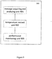
- Fig.9 shows a device for monitoring the performance of the APU lubricant cooler according to one embodiment of the invention.
- the device 900 for monitoring the performance of the APU lubricant cooler comprises message acquiring and analyzing unit 901, temperature revised unit 902 and performance monitoring unit 903.
- the relevant operation data of APU can be acquired by aircraft data system (such as ACMS or AHM system) and be embodied in the relevant messages generated. This kind of message information can be transferred to the ground by ACARS system, and further distributed to the servers of different airlines. According to one embodiment of the invention, APU message can also be transferred by the communicating device or system of Aviation Telecommunication Network (ATN).
- the message acquiring and analyzing unit can obtain the APU message within a time period, and analyze the desired operation data of the lubricant cooler.
- the operation data of APU lubricant cooler obtained by message acquiring and analyzing unit 901, such as the time since installation (TSR) of APU, lubricant temperature OTA and load compressor inlet temperature (LCIT).
- the temperature revised unit 902 revises the lubricant temperature.
- Performance monitoring unit 903 determines that the performance of the APU lubricant cooler is in stable phase, decline phase, serious decline phase or malfunction phase according to the change trend of the revised lubricant cooler OT against the time since installation (TSR) of APU.
- the monitoring method can be similar as the above-stated embodiments of the invention.
- the invention can be carried out by the device for monitoring the performance of APU lubricant cooler.
- the device comprises processor and memory.
- the memory stores the computer-readable codes.
- the computer-readable codes can be performed in the processor to implement the method for monitoring the performance of APU lubricant cooler disclosed in the above embodiments of the invention.
Landscapes
- Engineering & Computer Science (AREA)
- Chemical & Material Sciences (AREA)
- Combustion & Propulsion (AREA)
- Mechanical Engineering (AREA)
- General Engineering & Computer Science (AREA)
- Aviation & Aerospace Engineering (AREA)
- Physics & Mathematics (AREA)
- General Physics & Mathematics (AREA)
- Testing And Monitoring For Control Systems (AREA)
- Lubricants (AREA)
- Lubrication Details And Ventilation Of Internal Combustion Engines (AREA)
- Testing Of Devices, Machine Parts, Or Other Structures Thereof (AREA)
Claims (14)
- Verfahren zur Überwachung des Verhaltens eines Schmiermittelkühlers (100) für eine Luftfahrzeugshilfsleistungseinheit, APU, gekennzeichnet durch:Erfassen von APU-Nachrichten innerhalb einer Zeitspanne;Erhalten von Betriebsparametern des APU-Schmiermittelkühlers (100) entsprechend den APU-Nachrichten, wobei die Betriebsparameter eine Schmiermitteltemperatur (OTA) und eine Lastkompressoreinlasstemperatur (LCIT) beinhalten;Ermitteln einer revidierten Schmiermitteltemperatur (OT) durch die folgende Formel:revidierte Schmiermitteltemperatur (OT) = Schmiermitteltemperatur (OTA) - Lastkompressoreinlasstemperatur (LCIT); undErmitteln, ob das Leistungsverhalten des APU-Schmiermittelkühlers in einer stabilen Phase, einer abnehmenden Phase oder in einer Fehlfunktionsphase ist, gemäß einem Änderungstrend der revidierten Schmiermitteltemperatur (OT) in Abhängigkeit von der Zeit.
- Verfahren nach Anspruch 1, wobei der Schritt des Ermittelns des Leistungsverhaltens des APU-Schmiermittelkühlers bezüglich einer stabilen Phase, einer abnehmenden Phase oder einer Fehlfunktionsphase umfasst:in Reaktion darauf, dass der Änderungstrend kleiner als ein Schwellenwert für das Abnehmen ist, Bestimmen, dass das Leistungsverhalten des APU-Schmiermittelkühlers in einer stabilen Phase liegt; oderin Reaktion darauf, dass der Änderungstrend größer als der Schwellenwert für das Abnehmen und kleiner als ein Schwellenwert für eine Fehlfunktion ist, Bestimmen, dass das Leistungsverhalten des APU-Schmiermittelkühlers in einer abnehmenden Phase ist; oderin Reaktion darauf, dass der Änderungstrend größer als der Schwellenwert der Fehlfunktion ist, Bestimmen, dass das Leistungsverhalten des APU-Schmiermittelkühlers in einer Fehlfunktionsphase ist.
- Verfahren nach Anspruch 2, das ferner umfasst:Ermitteln des stabilen Änderungstrends der revidierten Schmiermitteltemperatur (OT) in Abhängigkeit von der Zeit, wenn der APU-Schmiermittelkühler in einer stabilen Phase ist;wobei der Schwellenwert für die abnehmende Phase ungefähr dem 1,5-2,5-fachen des stabilen Änderungstrends entspricht und der Schwellenwert für die Fehlfunktion ungefähr dem 5-7-fachen des stabilen Änderungstrends entspricht.
- Verfahren nach Anspruch 2, wobei die abnehmende Phase ferner eine erhebliche abnehmende Phase umfasst und der Schwellenwert für die erhebliche Abnahme zwischen den Schwellenwerten der Abnahme und der Fehlfunktion liegt, wobei die Reaktion auf den Änderungstrend größer als der Schwellenwert der erheblichen Abnahme und kleiner als der Schwellenwert der Fehlfunktion ist, wobei das Leistungsverhalten des APU-Schmiermittelkühlers als in der erheblichen Abnahmephase liegend ermittelt wird;
wobei das Verfahren ferner umfasst:Ermitteln, dass der stabile Änderungstrend der revidierten Schmiermitteltemperatur (OT) in Abhängigkeit von der Zeit vorliegt, wenn der APU-Schmiermittelkühler in der stabilen Phase ist;wobei der Schwellenwert der erheblichen Abnahme ungefähr dem 2,5-5-fachen des stabilen Änderungstrends ist. - Verfahren nach Anspruch 1, wobei die APU-Nachrichten so ausgelöst werden, dass die Betriebsparameter erhalten werden, wenn die APU-Belastung an ihrem Höchstwert liegt, oder wobei mehrere der APU-Nachrichten so ausgelöst werden, dass die Betriebsparameter bei gleicher APU-Belastung erhalten werden.
- Verfahren nach Anspruch 1, das ferner umfasst:in Reaktion darauf, dass die Schmiermitteltemperatur (OTA) den ersten Schwellenwert übersteigt, Ausgeben eines Warnsignals; oderin Reaktion darauf, dass die revidierte Schmiermitteltemperatur (OT) den zweiten Schwellenwert übersteigt, Ausgeben des Warnsignals.
- Verfahren nach Anspruch 1, das ferner umfasst:Berechnen des Mittelwerts, AVG, und des Abweichungsindex, δ, der revidierten Schmiermitteltemperatur (OT) innerhalb der Zeitspanne;Bestimmen der revidierten Schmiermitteltemperatur, OTnext, die gemäß der nächsten Nachricht, die die APU betrifft, erhalten wird; undin Reaktion darauf, dass OTnext größer als AVG+nδ oder kleiner als AVG-nδ ist, Ermitteln,ob die revidierte Schmiermitteltemperatur, OTnext+1, die gemäß der weiteren nächsten Nachricht erhalten wird, die die APU betrifft, in gleicher Weise größer als AVG+nδ oderkleiner als AVG-nδ ist;in Reaktion darauf, dass die revidierte Schmiermitteltemperatur, die gemäß der Nachricht erhalten wird, die die APU betrifft, in gleicher Weise kontinuierlich größer als AVG+nδ oderkleiner als AVG-nδ ist und eine vorbestimmte Anzahl Z übersteigt, Ausgeben der Warnung;wobei n 2-5 und Z 3-5 ist.
- Verfahren nach Anspruch 7, wobei in Reaktion darauf, dass die revidierte Schmiermitteltemperatur, die gemäß der die APU betreffenden Nachricht ermittelt wird, größer als AVG+nδ oder kleiner als AVG-nδ ist, Neuberechnen des Mittelwerts, AVG, und des Abweichungsindex, δ, der revidierten Schmiermitteltemperatur (OT); oder
in Reaktion darauf, dass die revidierte Schmiermitteltemperatur, die gemäß der die APU betreffenden Nachricht ermittelt wird, in gleicher Weise kontinuierlich größer als AVG+nδ oder kleiner als AVG-nδ ist und die vorbestimmte Anzahl Z übersteigt, Neuberechnen des Mittelwerts, AVG, und des Abweichungsindex, δ, der revidierten Schmiermitteltemperatur (OT). - Verfahren nach Anspruch 7, wobei der Abweichungsindex, δ, die Standardabweichung ist.
- Verfahren nach Anspruch 7, wobei der Wert von n gleich 2 oder 3 ist.
- Verfahren nach einem der Ansprüche 7-10, wobei der Wert von Z gleich 3 ist.
- Verfahren nach einem der Ansprüche 7-10, das ferner umfasst:in Reaktion darauf, dass die revidierte Schmiermitteltemperatur, die entsprechend der die APU betreffenden Nachricht ermittelt wird, kontinuierlich größer als AVG+nδ ist und die vorbestimmte Anzahl Z übersteigt, Ausgeben der Warnung des Schmiermittelkühlers, oderin Reaktion darauf, dass die revidierte Schmiermitteltemperatur, die gemäß der die APU betreffende Nachricht ermittelt wird, kontinuierlich größer ist als AVG-nδ und die vorbestimmte Anzahl Z übersteigt, Ausgeben der Warnung des Sensors.
- Verfahren nach Anspruch 1, das ferner umfasst: Abschätzen der Zeit, wann der Schmiermittelsensor eine Fehlfunktion hat.
- Einrichtung zur Überwachung des Leistungsverhaltens eines Schmiermittelkühlers in einer Luftfahrzeughilfsleistungseinheit, APU, gekennzeichnet durch:eine Nachrichtenerfassungs- und Auswerteeinheit, die die APU-Nachrichten innerhalb einer Zeitspanne erfasst und die Betriebsparameter des APU-Schmiermittelkühlers ermittelt,wobei die Betriebsparameter enthalten: die Zeitdauer seit der Installation (TSR) der APU, die Schmiermitteltemperatur (OTA) und die Lastkompressoreinlasstemperatur (LCIT);eine Temperaturüberarbeitungseinheit, die die revidierte Temperatur des Schmiermittels (OT) ermittelt, mit:revidierte Temperatur des Schmiermittels (OT) = Schmiermitteltemperatur (OTA) - Lastkompressoreinlasstemperatur (LCIT); undeine Leistungsverhaltensüberwachungseinheit, die gemäß dem Änderungstrend der revidierten Temperatur des Schmiermittelkühlers (OT) in Abhängigkeit von der Zeit seit der Installation (TSR) der APU ermittelt, ob das Leistungsverhalten des APU-Schmiermittelkühlers in einer stabilen Phase, einer abnehmenden Phase, einer erheblichen abnehmenden Phase oder einer Fehlfunktionsphase ist.
Applications Claiming Priority (1)
| Application Number | Priority Date | Filing Date | Title |
|---|---|---|---|
| CN201310313876.7A CN104340369B (zh) | 2013-07-24 | 2013-07-24 | 飞机辅助动力单元滑油冷却器性能监控方法及装置 |
Publications (3)
| Publication Number | Publication Date |
|---|---|
| EP2829696A2 EP2829696A2 (de) | 2015-01-28 |
| EP2829696A3 EP2829696A3 (de) | 2015-02-25 |
| EP2829696B1 true EP2829696B1 (de) | 2018-07-18 |
Family
ID=51260607
Family Applications (1)
| Application Number | Title | Priority Date | Filing Date |
|---|---|---|---|
| EP14178342.3A Active EP2829696B1 (de) | 2013-07-24 | 2014-07-24 | Verfahren zur Überwachung der Leistung des Schmiermittelkühlers in einer Flugzeughilfsturbineneinheit |
Country Status (9)
| Country | Link |
|---|---|
| US (1) | US9689311B2 (de) |
| EP (1) | EP2829696B1 (de) |
| JP (1) | JP6205318B2 (de) |
| KR (1) | KR102003896B1 (de) |
| CN (1) | CN104340369B (de) |
| AU (1) | AU2014206180B2 (de) |
| CA (1) | CA2857795C (de) |
| SG (1) | SG10201404347SA (de) |
| TW (1) | TWI619645B (de) |
Families Citing this family (17)
| Publication number | Priority date | Publication date | Assignee | Title |
|---|---|---|---|---|
| CN106741978B (zh) * | 2016-12-30 | 2023-09-29 | 重庆驼航科技有限公司 | 一种直升机用一体化复合式冷却系统 |
| US10082243B1 (en) | 2017-06-13 | 2018-09-25 | Pratt & Whitney Canada Corp. | Method and system for inlet blockage detection |
| CN109738195B (zh) * | 2018-12-28 | 2020-12-08 | 成都国营锦江机器厂 | Safir辅助动力装置起动试验模拟器及控制方法 |
| TWI841671B (zh) * | 2019-01-24 | 2024-05-11 | 日商第一三共股份有限公司 | 具有取代基之脲化合物 |
| US11518545B2 (en) * | 2019-04-17 | 2022-12-06 | The Boeing Company | Supplemental cooling unit prediction system |
| CN111056024B (zh) * | 2019-11-25 | 2022-07-19 | 中国南方航空股份有限公司 | 一种飞机辅助动力单元运行状态监控装置 |
| CN110925096A (zh) * | 2019-12-05 | 2020-03-27 | 中国航发四川燃气涡轮研究院 | 一种发动机滑油冷却系统 |
| US11551484B2 (en) | 2020-02-07 | 2023-01-10 | The Boeing Company | Vapor cycle machine management system |
| CN113311886A (zh) * | 2021-04-26 | 2021-08-27 | 中国船舶重工集团公司第七0三研究所 | 一种自适应滑油温度控制方法 |
| CN113291488B (zh) * | 2021-04-30 | 2022-01-04 | 浙江长龙航空有限公司 | 一种整体驱动发电机性能监控方法及装置 |
| CN113624505B (zh) * | 2021-08-24 | 2022-10-28 | 中国航发湖南动力机械研究所 | 一种压气机出口流场模拟装置 |
| CN115200883A (zh) * | 2022-05-12 | 2022-10-18 | 观典防务技术股份有限公司 | 一种监测无人机发动机熄火控制装置 |
| CN118733086B (zh) * | 2024-06-27 | 2026-01-06 | 奇瑞汽车股份有限公司 | 车辆ota软件升级系统、车辆及控制方法 |
| CN119429157B (zh) * | 2024-11-13 | 2025-11-25 | 中国南方航空股份有限公司 | 一种航空滑油冷却器的维护方法、系统、设备和介质 |
| CN119756873B (zh) * | 2024-12-03 | 2025-10-21 | 中国航发沈阳发动机研究所 | 一种航空发动机空气滑油散热器故障监测方法 |
| CN119717936B (zh) * | 2024-12-06 | 2025-08-12 | 中维化纤股份有限公司 | 一种熔体输送过程的工艺参数优化方法 |
| CN120141639B (zh) * | 2025-05-16 | 2025-09-16 | 洛阳乾禾仪器有限公司 | 一种基于人工智能的光纤振动传感器运行性能监测系统 |
Family Cites Families (17)
| Publication number | Priority date | Publication date | Assignee | Title |
|---|---|---|---|---|
| US5343778A (en) * | 1992-11-09 | 1994-09-06 | Alliedsignal Inc. | Multifunction secondary power system |
| US6470735B1 (en) | 2000-02-22 | 2002-10-29 | Meritor Heavy Vehicle Systems, Llc | Simple driveline condition sensing system |
| US7168254B2 (en) * | 2004-02-17 | 2007-01-30 | Honeywell International Inc. | Control logic for fuel controls on APUs |
| US7062370B2 (en) * | 2004-03-30 | 2006-06-13 | Honeywell International Inc. | Model-based detection, diagnosis of turbine engine faults |
| US7693643B2 (en) * | 2005-02-14 | 2010-04-06 | Honeywell International Inc. | Fault detection system and method for turbine engine fuel systems |
| US7805947B2 (en) * | 2005-05-19 | 2010-10-05 | Djamal Moulebhar | Aircraft with disengageable engine and auxiliary power unit components |
| US7369932B2 (en) * | 2006-05-04 | 2008-05-06 | Honeywell International, Inc. | System and method for turbine engine fault detection using discrete event system modeling |
| WO2009020229A1 (ja) * | 2007-08-09 | 2009-02-12 | Hitachi Construction Machinery Co., Ltd. | 作業機械の機器診断装置及び機器診断システム |
| US20090048730A1 (en) * | 2007-08-17 | 2009-02-19 | General Electric Company | Method and system for planning repair of an engine |
| US8467949B2 (en) * | 2009-05-29 | 2013-06-18 | Honeywell International Inc. | Methods and systems for turbine line replaceable unit fault detection and isolation during engine startup |
| US20120312023A1 (en) * | 2011-06-08 | 2012-12-13 | Honeywell International Inc. | Thermal management systems and methods for auxiliary power units |
| CN102320382A (zh) * | 2011-07-07 | 2012-01-18 | 中国国际航空股份有限公司 | 飞机性能检测方法 |
| CN102343983A (zh) * | 2011-07-07 | 2012-02-08 | 中国国际航空股份有限公司 | 飞机apu性能检测方法 |
| CN102416821A (zh) * | 2011-07-27 | 2012-04-18 | 中国国际航空股份有限公司 | 飞机系统数据处理方法 |
| US10094292B2 (en) * | 2012-03-02 | 2018-10-09 | Hamilton Sundstrand Corporation | Method of acceleration control during APU starting |
| CN104345273B (zh) * | 2013-07-24 | 2017-11-24 | 中国国际航空股份有限公司 | 飞机辅助动力单元起动机性能检测方法和装置 |
| CN104348670B (zh) * | 2013-07-24 | 2018-01-30 | 中国国际航空股份有限公司 | 飞机辅助动力单元燃油组件性能检测方法和装置 |
-
2013
- 2013-07-24 CN CN201310313876.7A patent/CN104340369B/zh active Active
-
2014
- 2014-07-23 SG SG10201404347SA patent/SG10201404347SA/en unknown
- 2014-07-23 US US14/338,568 patent/US9689311B2/en active Active
- 2014-07-24 KR KR1020140094106A patent/KR102003896B1/ko active Active
- 2014-07-24 EP EP14178342.3A patent/EP2829696B1/de active Active
- 2014-07-24 CA CA2857795A patent/CA2857795C/en active Active
- 2014-07-24 AU AU2014206180A patent/AU2014206180B2/en active Active
- 2014-07-24 TW TW103125399A patent/TWI619645B/zh active
- 2014-07-24 JP JP2014151058A patent/JP6205318B2/ja active Active
Non-Patent Citations (1)
| Title |
|---|
| None * |
Also Published As
| Publication number | Publication date |
|---|---|
| CN104340369A (zh) | 2015-02-11 |
| CA2857795C (en) | 2018-09-18 |
| JP2015038346A (ja) | 2015-02-26 |
| US20160230659A1 (en) | 2016-08-11 |
| SG10201404347SA (en) | 2015-02-27 |
| AU2014206180A1 (en) | 2015-02-12 |
| KR20150012222A (ko) | 2015-02-03 |
| TWI619645B (zh) | 2018-04-01 |
| CA2857795A1 (en) | 2015-01-24 |
| US9689311B2 (en) | 2017-06-27 |
| AU2014206180B2 (en) | 2017-10-12 |
| HK1202100A1 (en) | 2015-09-18 |
| CN104340369B (zh) | 2017-03-08 |
| TW201512041A (zh) | 2015-04-01 |
| KR102003896B1 (ko) | 2019-07-26 |
| JP6205318B2 (ja) | 2017-09-27 |
| EP2829696A3 (de) | 2015-02-25 |
| EP2829696A2 (de) | 2015-01-28 |
Similar Documents
| Publication | Publication Date | Title |
|---|---|---|
| EP2829696B1 (de) | Verfahren zur Überwachung der Leistung des Schmiermittelkühlers in einer Flugzeughilfsturbineneinheit | |
| TWI624584B (zh) | 發動機滑油監控系統及其方法與評估發動機性能方法 | |
| CA2857748C (en) | Method and device for monitoring the malfunction of apu turbine vane fracture and rotor shaft jam | |
| EP3312604B1 (de) | Ölrückstandsnachweiser mit adaptivem lernen | |
| US12276567B2 (en) | Method and system for monitoring a status of a reducer of a gas turbine | |
| EP3279650A1 (de) | Systeme und verfahren zur detektion von spänen in flüssigkeiten eines flugzeugmotors | |
| JP6205322B2 (ja) | 飛行機の補助動力ユニットの燃油ユニットの性能検出の方法と装置 | |
| CN104303122A (zh) | 通过自动确定判定阈来监测飞机机载设备老化的方法 | |
| US20150073650A1 (en) | Method for monitoring a degradation in an on-board device of an aircraft with automatic determination of a decision threshold | |
| HK1202100B (en) | Method and apparatus for monitoring performance of the lubricant cooler in aircraft auxiliary power unit | |
| CN120233700A (zh) | 一种空客机型epr波动的监控方法、装置及存储介质 | |
| CN118153294A (zh) | 发动机防喘振装置故障预测方法、装置、设备和存储介质 | |
| CN119719613A (zh) | 一种飞机发动机反推隔热层破损监控方法和系统 | |
| Whitby | Monitoring aviation gas turbines | |
| HK1202348B (en) | Method and apparatus for detecting performance of an apu fuel assembly | |
| HK1202323B (en) | System and method for monitoring lubricant of an engine |
Legal Events
| Date | Code | Title | Description |
|---|---|---|---|
| PUAL | Search report despatched |
Free format text: ORIGINAL CODE: 0009013 |
|
| 17P | Request for examination filed |
Effective date: 20140724 |
|
| AK | Designated contracting states |
Kind code of ref document: A2 Designated state(s): AL AT BE BG CH CY CZ DE DK EE ES FI FR GB GR HR HU IE IS IT LI LT LU LV MC MK MT NL NO PL PT RO RS SE SI SK SM TR |
|
| AX | Request for extension of the european patent |
Extension state: BA ME |
|
| PUAI | Public reference made under article 153(3) epc to a published international application that has entered the european phase |
Free format text: ORIGINAL CODE: 0009012 |
|
| AK | Designated contracting states |
Kind code of ref document: A3 Designated state(s): AL AT BE BG CH CY CZ DE DK EE ES FI FR GB GR HR HU IE IS IT LI LT LU LV MC MK MT NL NO PL PT RO RS SE SI SK SM TR |
|
| AX | Request for extension of the european patent |
Extension state: BA ME |
|
| RIC1 | Information provided on ipc code assigned before grant |
Ipc: F01M 5/00 20060101AFI20150119BHEP Ipc: F01M 11/10 20060101ALN20150119BHEP |
|
| R17P | Request for examination filed (corrected) |
Effective date: 20150825 |
|
| RBV | Designated contracting states (corrected) |
Designated state(s): AL AT BE BG CH CY CZ DE DK EE ES FI FR GB GR HR HU IE IS IT LI LT LU LV MC MK MT NL NO PL PT RO RS SE SI SK SM TR |
|
| GRAP | Despatch of communication of intention to grant a patent |
Free format text: ORIGINAL CODE: EPIDOSNIGR1 |
|
| INTG | Intention to grant announced |
Effective date: 20180119 |
|
| GRAJ | Information related to disapproval of communication of intention to grant by the applicant or resumption of examination proceedings by the epo deleted |
Free format text: ORIGINAL CODE: EPIDOSDIGR1 |
|
| GRAP | Despatch of communication of intention to grant a patent |
Free format text: ORIGINAL CODE: EPIDOSNIGR1 |
|
| INTC | Intention to grant announced (deleted) | ||
| INTG | Intention to grant announced |
Effective date: 20180228 |
|
| GRAS | Grant fee paid |
Free format text: ORIGINAL CODE: EPIDOSNIGR3 |
|
| GRAA | (expected) grant |
Free format text: ORIGINAL CODE: 0009210 |
|
| AK | Designated contracting states |
Kind code of ref document: B1 Designated state(s): AL AT BE BG CH CY CZ DE DK EE ES FI FR GB GR HR HU IE IS IT LI LT LU LV MC MK MT NL NO PL PT RO RS SE SI SK SM TR |
|
| REG | Reference to a national code |
Ref country code: GB Ref legal event code: FG4D |
|
| REG | Reference to a national code |
Ref country code: FR Ref legal event code: PLFP Year of fee payment: 5 |
|
| REG | Reference to a national code |
Ref country code: CH Ref legal event code: EP |
|
| REG | Reference to a national code |
Ref country code: IE Ref legal event code: FG4D |
|
| REG | Reference to a national code |
Ref country code: AT Ref legal event code: REF Ref document number: 1019604 Country of ref document: AT Kind code of ref document: T Effective date: 20180815 |
|
| REG | Reference to a national code |
Ref country code: DE Ref legal event code: R096 Ref document number: 602014028582 Country of ref document: DE |
|
| REG | Reference to a national code |
Ref country code: NL Ref legal event code: MP Effective date: 20180718 |
|
| REG | Reference to a national code |
Ref country code: LT Ref legal event code: MG4D |
|
| REG | Reference to a national code |
Ref country code: AT Ref legal event code: MK05 Ref document number: 1019604 Country of ref document: AT Kind code of ref document: T Effective date: 20180718 |
|
| PG25 | Lapsed in a contracting state [announced via postgrant information from national office to epo] |
Ref country code: NL Free format text: LAPSE BECAUSE OF FAILURE TO SUBMIT A TRANSLATION OF THE DESCRIPTION OR TO PAY THE FEE WITHIN THE PRESCRIBED TIME-LIMIT Effective date: 20180718 |
|
| PG25 | Lapsed in a contracting state [announced via postgrant information from national office to epo] |
Ref country code: PL Free format text: LAPSE BECAUSE OF FAILURE TO SUBMIT A TRANSLATION OF THE DESCRIPTION OR TO PAY THE FEE WITHIN THE PRESCRIBED TIME-LIMIT Effective date: 20180718 Ref country code: LT Free format text: LAPSE BECAUSE OF FAILURE TO SUBMIT A TRANSLATION OF THE DESCRIPTION OR TO PAY THE FEE WITHIN THE PRESCRIBED TIME-LIMIT Effective date: 20180718 Ref country code: BG Free format text: LAPSE BECAUSE OF FAILURE TO SUBMIT A TRANSLATION OF THE DESCRIPTION OR TO PAY THE FEE WITHIN THE PRESCRIBED TIME-LIMIT Effective date: 20181018 Ref country code: GR Free format text: LAPSE BECAUSE OF FAILURE TO SUBMIT A TRANSLATION OF THE DESCRIPTION OR TO PAY THE FEE WITHIN THE PRESCRIBED TIME-LIMIT Effective date: 20181019 Ref country code: NO Free format text: LAPSE BECAUSE OF FAILURE TO SUBMIT A TRANSLATION OF THE DESCRIPTION OR TO PAY THE FEE WITHIN THE PRESCRIBED TIME-LIMIT Effective date: 20181018 Ref country code: SE Free format text: LAPSE BECAUSE OF FAILURE TO SUBMIT A TRANSLATION OF THE DESCRIPTION OR TO PAY THE FEE WITHIN THE PRESCRIBED TIME-LIMIT Effective date: 20180718 Ref country code: IS Free format text: LAPSE BECAUSE OF FAILURE TO SUBMIT A TRANSLATION OF THE DESCRIPTION OR TO PAY THE FEE WITHIN THE PRESCRIBED TIME-LIMIT Effective date: 20181118 Ref country code: AT Free format text: LAPSE BECAUSE OF FAILURE TO SUBMIT A TRANSLATION OF THE DESCRIPTION OR TO PAY THE FEE WITHIN THE PRESCRIBED TIME-LIMIT Effective date: 20180718 Ref country code: RS Free format text: LAPSE BECAUSE OF FAILURE TO SUBMIT A TRANSLATION OF THE DESCRIPTION OR TO PAY THE FEE WITHIN THE PRESCRIBED TIME-LIMIT Effective date: 20180718 Ref country code: FI Free format text: LAPSE BECAUSE OF FAILURE TO SUBMIT A TRANSLATION OF THE DESCRIPTION OR TO PAY THE FEE WITHIN THE PRESCRIBED TIME-LIMIT Effective date: 20180718 |
|
| PG25 | Lapsed in a contracting state [announced via postgrant information from national office to epo] |
Ref country code: HR Free format text: LAPSE BECAUSE OF FAILURE TO SUBMIT A TRANSLATION OF THE DESCRIPTION OR TO PAY THE FEE WITHIN THE PRESCRIBED TIME-LIMIT Effective date: 20180718 Ref country code: AL Free format text: LAPSE BECAUSE OF FAILURE TO SUBMIT A TRANSLATION OF THE DESCRIPTION OR TO PAY THE FEE WITHIN THE PRESCRIBED TIME-LIMIT Effective date: 20180718 Ref country code: LV Free format text: LAPSE BECAUSE OF FAILURE TO SUBMIT A TRANSLATION OF THE DESCRIPTION OR TO PAY THE FEE WITHIN THE PRESCRIBED TIME-LIMIT Effective date: 20180718 |
|
| REG | Reference to a national code |
Ref country code: CH Ref legal event code: PL |
|
| PG25 | Lapsed in a contracting state [announced via postgrant information from national office to epo] |
Ref country code: LU Free format text: LAPSE BECAUSE OF NON-PAYMENT OF DUE FEES Effective date: 20180724 |
|
| REG | Reference to a national code |
Ref country code: BE Ref legal event code: MM Effective date: 20180731 |
|
| REG | Reference to a national code |
Ref country code: IE Ref legal event code: MM4A |
|
| REG | Reference to a national code |
Ref country code: DE Ref legal event code: R097 Ref document number: 602014028582 Country of ref document: DE |
|
| PG25 | Lapsed in a contracting state [announced via postgrant information from national office to epo] |
Ref country code: ES Free format text: LAPSE BECAUSE OF FAILURE TO SUBMIT A TRANSLATION OF THE DESCRIPTION OR TO PAY THE FEE WITHIN THE PRESCRIBED TIME-LIMIT Effective date: 20180718 Ref country code: LI Free format text: LAPSE BECAUSE OF NON-PAYMENT OF DUE FEES Effective date: 20180731 Ref country code: MC Free format text: LAPSE BECAUSE OF FAILURE TO SUBMIT A TRANSLATION OF THE DESCRIPTION OR TO PAY THE FEE WITHIN THE PRESCRIBED TIME-LIMIT Effective date: 20180718 Ref country code: EE Free format text: LAPSE BECAUSE OF FAILURE TO SUBMIT A TRANSLATION OF THE DESCRIPTION OR TO PAY THE FEE WITHIN THE PRESCRIBED TIME-LIMIT Effective date: 20180718 Ref country code: CH Free format text: LAPSE BECAUSE OF NON-PAYMENT OF DUE FEES Effective date: 20180731 Ref country code: IT Free format text: LAPSE BECAUSE OF FAILURE TO SUBMIT A TRANSLATION OF THE DESCRIPTION OR TO PAY THE FEE WITHIN THE PRESCRIBED TIME-LIMIT Effective date: 20180718 Ref country code: RO Free format text: LAPSE BECAUSE OF FAILURE TO SUBMIT A TRANSLATION OF THE DESCRIPTION OR TO PAY THE FEE WITHIN THE PRESCRIBED TIME-LIMIT Effective date: 20180718 Ref country code: IE Free format text: LAPSE BECAUSE OF NON-PAYMENT OF DUE FEES Effective date: 20180724 Ref country code: CZ Free format text: LAPSE BECAUSE OF FAILURE TO SUBMIT A TRANSLATION OF THE DESCRIPTION OR TO PAY THE FEE WITHIN THE PRESCRIBED TIME-LIMIT Effective date: 20180718 |
|
| PLBE | No opposition filed within time limit |
Free format text: ORIGINAL CODE: 0009261 |
|
| STAA | Information on the status of an ep patent application or granted ep patent |
Free format text: STATUS: NO OPPOSITION FILED WITHIN TIME LIMIT |
|
| PG25 | Lapsed in a contracting state [announced via postgrant information from national office to epo] |
Ref country code: BE Free format text: LAPSE BECAUSE OF NON-PAYMENT OF DUE FEES Effective date: 20180731 Ref country code: DK Free format text: LAPSE BECAUSE OF FAILURE TO SUBMIT A TRANSLATION OF THE DESCRIPTION OR TO PAY THE FEE WITHIN THE PRESCRIBED TIME-LIMIT Effective date: 20180718 Ref country code: SK Free format text: LAPSE BECAUSE OF FAILURE TO SUBMIT A TRANSLATION OF THE DESCRIPTION OR TO PAY THE FEE WITHIN THE PRESCRIBED TIME-LIMIT Effective date: 20180718 Ref country code: SM Free format text: LAPSE BECAUSE OF FAILURE TO SUBMIT A TRANSLATION OF THE DESCRIPTION OR TO PAY THE FEE WITHIN THE PRESCRIBED TIME-LIMIT Effective date: 20180718 |
|
| 26N | No opposition filed |
Effective date: 20190423 |
|
| PG25 | Lapsed in a contracting state [announced via postgrant information from national office to epo] |
Ref country code: SI Free format text: LAPSE BECAUSE OF FAILURE TO SUBMIT A TRANSLATION OF THE DESCRIPTION OR TO PAY THE FEE WITHIN THE PRESCRIBED TIME-LIMIT Effective date: 20180718 |
|
| PG25 | Lapsed in a contracting state [announced via postgrant information from national office to epo] |
Ref country code: MT Free format text: LAPSE BECAUSE OF NON-PAYMENT OF DUE FEES Effective date: 20180724 |
|
| PG25 | Lapsed in a contracting state [announced via postgrant information from national office to epo] |
Ref country code: TR Free format text: LAPSE BECAUSE OF FAILURE TO SUBMIT A TRANSLATION OF THE DESCRIPTION OR TO PAY THE FEE WITHIN THE PRESCRIBED TIME-LIMIT Effective date: 20180718 |
|
| PG25 | Lapsed in a contracting state [announced via postgrant information from national office to epo] |
Ref country code: PT Free format text: LAPSE BECAUSE OF FAILURE TO SUBMIT A TRANSLATION OF THE DESCRIPTION OR TO PAY THE FEE WITHIN THE PRESCRIBED TIME-LIMIT Effective date: 20180718 Ref country code: HU Free format text: LAPSE BECAUSE OF FAILURE TO SUBMIT A TRANSLATION OF THE DESCRIPTION OR TO PAY THE FEE WITHIN THE PRESCRIBED TIME-LIMIT; INVALID AB INITIO Effective date: 20140724 |
|
| PG25 | Lapsed in a contracting state [announced via postgrant information from national office to epo] |
Ref country code: MK Free format text: LAPSE BECAUSE OF NON-PAYMENT OF DUE FEES Effective date: 20180718 Ref country code: CY Free format text: LAPSE BECAUSE OF FAILURE TO SUBMIT A TRANSLATION OF THE DESCRIPTION OR TO PAY THE FEE WITHIN THE PRESCRIBED TIME-LIMIT Effective date: 20180718 |
|
| PGFP | Annual fee paid to national office [announced via postgrant information from national office to epo] |
Ref country code: DE Payment date: 20250724 Year of fee payment: 12 |
|
| PGFP | Annual fee paid to national office [announced via postgrant information from national office to epo] |
Ref country code: GB Payment date: 20250723 Year of fee payment: 12 |
|
| PGFP | Annual fee paid to national office [announced via postgrant information from national office to epo] |
Ref country code: FR Payment date: 20250728 Year of fee payment: 12 |