EP2829676A2 - Two or more independent hydraulic lock actuations - Google Patents
Two or more independent hydraulic lock actuations Download PDFInfo
- Publication number
- EP2829676A2 EP2829676A2 EP14178094.0A EP14178094A EP2829676A2 EP 2829676 A2 EP2829676 A2 EP 2829676A2 EP 14178094 A EP14178094 A EP 14178094A EP 2829676 A2 EP2829676 A2 EP 2829676A2
- Authority
- EP
- European Patent Office
- Prior art keywords
- door
- door lock
- operating system
- lock
- hydraulic
- Prior art date
- Legal status (The legal status is an assumption and is not a legal conclusion. Google has not performed a legal analysis and makes no representation as to the accuracy of the status listed.)
- Withdrawn
Links
Images
Classifications
-
- E—FIXED CONSTRUCTIONS
- E05—LOCKS; KEYS; WINDOW OR DOOR FITTINGS; SAFES
- E05B—LOCKS; ACCESSORIES THEREFOR; HANDCUFFS
- E05B81/00—Power-actuated vehicle locks
- E05B81/02—Power-actuated vehicle locks characterised by the type of actuators used
- E05B81/10—Hydraulic or pneumatic
-
- E—FIXED CONSTRUCTIONS
- E05—LOCKS; KEYS; WINDOW OR DOOR FITTINGS; SAFES
- E05B—LOCKS; ACCESSORIES THEREFOR; HANDCUFFS
- E05B81/00—Power-actuated vehicle locks
- E05B81/52—Pneumatic or hydraulic circuits
Definitions
- the invention relates to a door actuation system for a motor vehicle, comprising at least two hydraulic door lock actuators which can be activated via a door handle and a hydraulic Matverriegelungs- or Mosentriegelungs adopted associated with at least the two Schoschbetuschists promoteden, the Schoverriegelungs- or Mosentriegelungs acquired connected via a main line with at least one of the Mitschbetuschists promoteden is off, and a branch line from the main line to the other door lock or door unlocking at a Y-branch off / turns / branched off.
- Door actuation systems are also understood to mean systems which also actuate flaps or covers or hoods of vehicles, for example hoods, trunk lids, trunk lids or doors of a general nature.
- a branch is understood to mean a branch, which may also be designed as a switch, in order to distribute fluids such as liquids, in particular hydraulic fluids, such as oil, from one or more delivery devices to a receiving device or a plurality of receiving devices.
- fluids such as liquids, in particular hydraulic fluids, such as oil
- a typical example of this is a vehicle door in which a door closing module / closing module is actuated by both an inner and an outer door handle / door lever to open the door.
- Hydraulic door operations are already known prior art, such as from the DE 199 49 037 A1 , Also the EP 1 273 744 A2 and the DE 102 28 978 B4 are basically in this area.
- Locks for a door of a motor vehicle are also from the DE 199 49 037 A1 known. There it is disclosed that a door lock can be arranged on a door of a motor vehicle, which is coupled to a arranged on the door door handle to open the door lock, wherein the door handle is fluidly coupled to the door lock. Under a fluidic coupling is understood there a pneumatic or hydraulic actuation. It is disclosed that pneumatic or hydraulic couplings are realized.
- a hydraulically operated door lock is further in the US 2298776 disclosed.
- Devices for locking and unlocking door locks, using hydraulic devices, are also the US 4541258 refer to.
- the DE 10 2004 037 299 A1 further discloses a door operating device with a vehicle door with an adjustably mounted door handle, with a door lock, with a motion-transmitting transmission element between the adjustable door handle and a locking device of the door lock, and with a securing device which prevents an unlocking position opening the door lock in an accidental displacement tendency of the door handle.
- the transmission element has a closed transmission medium system which contains a transmission medium which comprises the transmission medium system a flexible, tubular transmission line, in the line course a line narrowing throttle is arranged so that a volume-displacement element is arranged on each side of the transmission line whose volumes filled with transmission medium are connected to each other through the transmission line containing the throttle and of which at least one of its sliding part is connected directly or indirectly in terms of movement with the door handle.
- EP 0 936 102 A1 discloses an actuator using hydraulic elements, but for a locking device on a vehicle seat.
- Locking and locking systems for doors or flaps are also from the pamphlets EP 1 273 744 A2 and DE 102 28 978 B4 disclosed. There are also disclosed special circuit diagrams for driving a slave cylinder by multiple master cylinder.
- a shuttle valve is arranged in the Y branch to block either the main line or the secondary line and to block one of the door lock or door unlocking devices from the door lock operating device.
- each door lock operating device is associated with a door lever or a door handle to trigger movement. This can be effected by manual force opening the door.
- An advantageous embodiment is also characterized in that the shuttle valve is designed to be operated manually or automatically, such as electrically and / or magnetically.
- At least one of the elements as a door lock operating device and door lock locking device or door lock unlocking device contains a pressure space volume-changing rolling diaphragm. Especially such rolling membranes allow a long life of the door operating system.
- each door actuator and door lock or lock release means comprises a housing and a relatively movable piston, whereby the hydraulic system can be kept simple and efficient.
- the piston of the door lock or door unlocking device acts on a latch of a closing module.
- the invention relates to a hydraulic Matver- or unlocking, in which by two or more independent lock operations, such as a door lever or a door handle, or more door lever or more door handles can be operated by means of hydraulics on the closing module.
- a typical example is a vehicle door in which both through the inner as well as through the outer door handle the closing module is operated to open the door.
- the known solutions are based on two or more independent hydraulic lines, each connecting a lock operation with the closing module.
- the independent hydraulic operation unfortunately caused in St. d. T. two complete hydraulic lines in which a cylinder of a lock operation and a cylinder in the lock module is required per line.
- the invention intervenes successfully to reduce the number of components. It is therefore proposed a direct connection of the hydraulic lines in the form of a Y-circuit or the use of a shuttle valve. With a shuttle valve, the other actuating cylinders are hydraulically shut off. The total effort is significantly reduced.
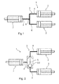
- FIG. 1 a first embodiment of a door actuation system 1 according to the invention is shown.
- the door operating system has two hydraulic door lock actuators 2.
- the door lock actuators 2 are basically designed as a hydraulic cylinder.
- a door lock or door unlocking device 7 is activated.
- a comparable door operating system 1 is also the FIG. 2 can be seen, but there, unlike in the embodiment according to the FIG. 1 , in the Y-branch 5, a valve 8, namely a shuttle valve 9 is included, which releases either the leading to the door lock actuator 2 main line branch or leading to the other door lock actuator bypass line branch, or shuts off.
Abstract
Die Erfindung betrifft ein Türbetätigungssystem für ein Kraftfahrzeug mit zumindest zwei hydraulischen Türschlossbetätigungseinrichtungen, die über einen Türgriff aktivierbar sind und einer zumindest den zwei Türschlossbetätigungseinrichtungen zugeordneten hydraulischen Türverriegelungs- oder Türentriegelungseinrichtung, wobei die Türverriegelungs- oder Türentriegelungseinrichtung über eine Hauptleitung mit wenigstens einer der Türschlossbetätigungseinrichtungen verbunden ist, und eine Nebenleitung von der Hauptleitung zur anderen Türverriegelungs- oder Türentriegelungseinrichtung an einem Y-Abzweig abzweigt / abgeht, wobei die Y-abzweigungsfernen Abschnitte der Hauptleitung und/oder der Nebenleitung absperrelementfrei ausgestaltet sind.The invention relates to a door actuation system for a motor vehicle having at least two hydraulic door lock actuators which can be activated via a door handle and a hydraulic door lock or door unlocking device associated with at least the two door lock actuators, the door lock or door unlocking device being connected via a main line to at least one of the door lock actuators, and a secondary line branches from the main line to the other door lock or door unlocking device at a Y-branch, the Y-junction-remote sections of the main line and / or the secondary line being designed barrier-free.
Description
Die Erfindung betrifft ein Türbetätigungssystem für ein Kraftfahrzeug, mit mindestens zwei hydraulischen Türschlossbetätigungseinrichtungen, die über einen Türgriff aktivierbar sind und einer zumindest den zwei Türschlossbetätigungseinrichtungen zugeordneten, hydraulischen Türverriegelungs- oder Türentriegelungseinrichtung, wobei die Türverriegelungs- oder Türentriegelungseinrichtung über eine Hauptleitung mit wenigstens einer der Türschlossbetätigungseinrichtungen verbunden ist, und eine Nebenleitung von der Hauptleitung zur anderen Türverriegelungs- oder Türentriegelungseinrichtung an einem Y-Abzweig abgeht/abbiegt/abzweigt.The invention relates to a door actuation system for a motor vehicle, comprising at least two hydraulic door lock actuators which can be activated via a door handle and a hydraulic Türverriegelungs- or Türentriegelungseinrichtung associated with at least the two Türschlossbetätigungseinrichtungen, the Türverriegelungs- or Türentriegelungseinrichtung connected via a main line with at least one of the Türschlossbetätigungseinrichtungen is off, and a branch line from the main line to the other door lock or door unlocking at a Y-branch off / turns / branched off.
Unter Türbetätigungssystemen werden auch solche Systeme verstanden, die auch Klappen oder Deckel oder Hauben von Fahrzeugen betätigen, also beispielsweise Motorhauben, Heckdeckel, Kofferraumdeckel oder Türen allgemeiner Natur.Door actuation systems are also understood to mean systems which also actuate flaps or covers or hoods of vehicles, for example hoods, trunk lids, trunk lids or doors of a general nature.
Unter einem Abzweig wird eine Verzweigung verstanden, die auch als Weiche ausgestaltet sein kann, um Fluide wie Flüssigkeiten, insbesondere Hydraulikflüssigkeiten, etwa Öl, von einem oder mehreren Gebereinrichtungen an eine Nehmereinrichtung oder mehrere Nehmereinrichtungen zu verteilen.A branch is understood to mean a branch, which may also be designed as a switch, in order to distribute fluids such as liquids, in particular hydraulic fluids, such as oil, from one or more delivery devices to a receiving device or a plurality of receiving devices.
Es gibt eine Vielzahl von Anwendungen, bei denen durch zwei oder mehrere unabhängige Schlossbetätigungen, z. B. Türhebel oder Türgriffe mittels Hydraulik ein Schließmodul betätigt werden soll. Ein typisches Beispiel hierfür ist eine Fahrzeugtür, bei der sowohl durch einen inneren als auch einen äußeren Türgriff/Türhebel ein Türschließmodul/Schließmodul betätigt wird, um die Tür zu öffnen.There are a variety of applications in which by two or more independent lock operations, eg. B. door lever or door handles by means of hydraulics a closing module to be actuated. A typical example of this is a vehicle door in which a door closing module / closing module is actuated by both an inner and an outer door handle / door lever to open the door.
Hydraulische Türbetätigungen sind bereits bekannter Stand der Technik, etwa aus der
Aus dem Stand der Technik sind bereits Betätigungssysteme für Türschlösser bekannt, etwa aus der
Schlösser für eine Tür eines Kraftfahrzeuges sind auch aus der
Ein hydraulisch betätigtes Türschloss wird ferner in der
Die
Einen ähnlichen Weg geht auch die
Verschluss- und Verriegelungssysteme für Türen oder Klappen sind auch aus den Druckschriften
Die bisher bekannten Betätigungssysteme, etwa solche, die Bowdenzüge verwenden, sind leider nicht wartungsfrei und sind gegenüber hydraulischen Systemen nachteilig. Bei hydraulischen Systemen muss jedoch ein Flüssigkeitsreservoir vorgehalten werden und in Kauf genommen werden, dass die üblichen, bewegten Dichtungen verschleißen, was wiederum zu Wartungsaktivitäten, wie dem Erneuern der Dichtungen und dem Nachfüllen von Hydraulikmittel führt.The previously known actuation systems, such as those using Bowden cables, are unfortunately not maintenance-free and are disadvantageous compared to hydraulic systems. For hydraulic However, systems must maintain a fluid reservoir and allow for the usual moving seals to wear, which in turn leads to maintenance activities such as replacement of the seals and replenishment of hydraulic fluid.
Es ist die Aufgabe der vorliegenden Erfindung, den Nachteil aus dem Stand der Technik zu verhindern, insbesondere unabhängige hydraulische Betätigungen von einer hydraulischen Türverriegelungs- oder Türentriegelungseinrichtung über zwei separate Türschlossbetätigungseinrichtungen zu ermöglichen, ohne jedoch zwei oder mehrere unabhängige hydraulische Leitungen komplett zu benötigen. Es soll eine Reduktion der Bauteile bewirkt werden und eine Einsparung eines Zylinders am Schließmodul erreicht werden.It is the object of the present invention to obviate the drawback of the prior art, in particular to allow independent hydraulic actuations of a hydraulic door lock or door unlocking device via two separate door lock actuators, without, however, completely requiring two or more independent hydraulic lines. It should be effected a reduction of the components and a saving of a cylinder on the closing module can be achieved.
Diese Aufgabe wird bei einem gattungsgemäßen Türbetätigungssystem dadurch erreicht, dass erfindungsgemäß die Y-abzweigungsfernen Abschnitte der Hauptleitung und/oder der Nebenleitung absperrelementfrei ausgestaltet sind, mit anderen Worten somit auch frei von Ventilen sind.This object is achieved in a generic door actuation system characterized in that according to the invention, the Y-branch remote sections of the main line and / or the secondary line are designed absperrelementfrei, in other words, therefore, are also free of valves.
Es wird somit eine Y-Anordnung einer hydraulischen Leitung, umfassend einer Hauptleitung und einer Nebenleitung vorgeschlagen. Somit wird nur ein Zylinder an dem Schließmodul benötigt. Dies kann durch eine einfache Verbindung der hydraulischen Leitungen oder durch Verbinden der Leitungen mittels eines Wechselventils erfolgen. Bei Verwendung eines Wechselventils werden die anderen Betätigungszylinder hydraulisch abgesperrt. Durch die Y-Anordnung der hydraulischen Leitungen wird im Vergleich zu bisherigen Konzepten ein Zylinderanschließmodul sowie ein Teil der hydraulischen Leitung eingespart. Dies bietet einen technischen Vorteil durch reduzierten Aufwand.It is thus proposed a Y-arrangement of a hydraulic line comprising a main line and a secondary line. Thus, only one cylinder is needed on the lock module. This can be done by a simple connection of the hydraulic lines or by connecting the lines by means of a shuttle valve. When using a shuttle valve, the other actuator cylinders are hydraulically shut off. By Y-arrangement of the hydraulic lines a Zylinderanschließmodul and a part of the hydraulic line is saved in comparison to previous concepts. This offers a technical advantage due to reduced effort.
Vorteilhafte Ausführungsformen werden in den Unteransprüchen beansprucht und nachfolgend näher erläutert.Advantageous embodiments are claimed in the subclaims and explained in more detail below.
Es ist von Vorteil, wenn im Y-Abzweig ein Wechselventil angeordnet ist, um entweder die Hauptleitung oder die Nebenleitung zu sperren und eine der Türverriegelungs- oder Türentriegelungseinrichtungen von der Türschlossbetätigungseinrichtung zu sperren.It is advantageous if a shuttle valve is arranged in the Y branch to block either the main line or the secondary line and to block one of the door lock or door unlocking devices from the door lock operating device.
Auch ist es von Vorteil, wenn jeder Türschlossbetätigungseinrichtung ein Türhebel oder ein Türgriff bewegungsauslösend zugeordnet ist. Dadurch kann durch Handkraft ein Öffnen der Tür bewirkt werden.It is also advantageous if each door lock operating device is associated with a door lever or a door handle to trigger movement. This can be effected by manual force opening the door.
Wenn ein erster Türgriff auf einer Türinnenseite und ein zweiter Türgriff auf einer Türaußenseite angeordnet ist, so bleibt die Türöffnenbarkeit von innen und außen gewährleistet.If a first door handle on a door inner side and a second door handle is arranged on a door outside, so the Türöffbarkeit remains guaranteed from inside and outside.
Ein vorteilhaftes Ausführungsbeispiel ist auch dadurch gekennzeichnet, dass das Wechselventil ausgelegt ist, um manuell oder automatisch, etwa elektrisch und/oder magnetisch, betätigt zu werden.An advantageous embodiment is also characterized in that the shuttle valve is designed to be operated manually or automatically, such as electrically and / or magnetically.
Zweckmäßig ist es ferner, wenn zumindest eines der Elemente als Türschlossbetätigungseinrichtung und Türschlossverriegelungs- oder Türschlossentriegelungseinrichtung eine druckraumvolumenverändernde Rollmembran enthält. Gerade solche Rollmembranen ermöglichen eine hohe Lebensdauer des Türbetätigungssystems.It is also expedient if at least one of the elements as a door lock operating device and door lock locking device or door lock unlocking device contains a pressure space volume-changing rolling diaphragm. Especially such rolling membranes allow a long life of the door operating system.
Weiter ist es von Vorteil, wenn jede Türbetätigungseinrichtung und Türschlossverriegelungs- oder Türschlossentriegelungseinrichtung ein Gehäuse und einen dazu relativ beweglichen Kolben aufweist, wodurch das hydraulische System einfach und effizient gehalten werden kann.Further, it is advantageous if each door actuator and door lock or lock release means comprises a housing and a relatively movable piston, whereby the hydraulic system can be kept simple and efficient.
Während der Kolben auf die Rollmembran, etwa in einen mittigen Bereich einwirkt, so wird eine gute Kraftübertragung und Verklemmverhinderung gewährleistet.While the piston acts on the rolling diaphragm, approximately in a central region, a good power transmission and Verklemmverhinderung is ensured.
Es ist ferner von Vorteil, wenn der Kolben aus dem Gehäuse ausfahrbar gelagert ist, um eine Erreichbarkeit von Betätigungsweitergabeorganen zu gewährleisten.It is also advantageous if the piston is mounted extendable out of the housing to ensure accessibility of Betätigungsweitergabeorganen.
Es ist auch vorteilhaft, wenn der Kolben der Türverriegelungs- oder Türentriegelungseinrichtung auf einen Riegel eines Schließmoduls einwirkt.It is also advantageous if the piston of the door lock or door unlocking device acts on a latch of a closing module.
Mit anderen Worten betrifft die Erfindung eine hydraulische Türver- oder-entriegelung, bei der durch zwei oder mehrere unabhängige Schlossbetätigungen, etwa über einen Türhebel oder einen Türgriff, bzw. mehrere Türhebel oder mehrere Türgriffe, mittels Hydraulik am Schließmodul betätigt werden kann. Ein typisches Beispiel ist eine Fahrzeugtür, bei der sowohl durch den inneren als auch durch den äußeren Türgriff das Schließmodul betätigt wird um die Tür zu öffnen.In other words, the invention relates to a hydraulic Türver- or unlocking, in which by two or more independent lock operations, such as a door lever or a door handle, or more door lever or more door handles can be operated by means of hydraulics on the closing module. A typical example is a vehicle door in which both through the inner as well as through the outer door handle the closing module is operated to open the door.
Die bekannten Lösungen gehen von zwei oder mehreren unabhängigen hydraulischen Leitungen aus, die jeweils eine Schlossbetätigung mit dem Schließmodul verbinden. Die unabhängige hydraulische Betätigung bedingt leider im St. d. T. zwei komplette hydraulische Leitungen, bei denen je Leitung ein Zylinder einer Schlossbetätigung und ein Zylinder in dem Schließmodul benötigt wird.The known solutions are based on two or more independent hydraulic lines, each connecting a lock operation with the closing module. The independent hydraulic operation unfortunately caused in St. d. T. two complete hydraulic lines in which a cylinder of a lock operation and a cylinder in the lock module is required per line.
Hier greift die Erfindung erfolgreich ein um die Anzahl der Bauteile zu reduzieren. Es wird daher eine direkte Verbindung der Hydraulikleitungen in Form einer Y-Schaltung oder die Verwendung eines Wechselventils vorgeschlagen. Mit einem Wechselventil werden die anderen Betätigungszylinder hydraulisch abgesperrt. Der Gesamtaufwand wird erheblich reduziert.Here the invention intervenes successfully to reduce the number of components. It is therefore proposed a direct connection of the hydraulic lines in the form of a Y-circuit or the use of a shuttle valve. With a shuttle valve, the other actuating cylinders are hydraulically shut off. The total effort is significantly reduced.
Die Erfindung wird nachfolgend mit Hilfe einer Zeichnung näher erläutert. Dabei werden zwei Ausführungsbeispiele dargestellt. Es zeigen:
- Figur 1
- eine erste Ausführungsform mit einer Y-Abzweigung von einer Hauptleitung in eine Nebenleitung gänzlich ohne Ventile, und
Figur 2- eine zweite Ausführungsform eines erfindungsgemäßen Türbetätigungssystems, wobei an der Stelle der Y-Abzweigung ein Wechselventil eingebaut ist.
- FIG. 1
- a first embodiment with a Y-branch from a main line to a secondary line entirely without valves, and
- FIG. 2
- a second embodiment of a door actuation system according to the invention, wherein at the location of the Y-branch a shuttle valve is installed.
Die Figuren sind lediglich schematischer Natur und dienen nur dem Verständnis der Erfindung. Die gleichen Elemente werden mit denselben Bezugszeichen versehen.The figures are merely schematic in nature and are only for the understanding of the invention. The same elements are given the same reference numerals.
In
Über ein Leitungssystem 3, umfassend eine Hauptleitung 4 und eine an einer Y-Abzweigung 5 abzweigende Nebenleitung 6 für Hydraulikflüssigkeit, wird eine Türverriegelungs- oder Türentriegelungseinrichtung 7 aktiviert.Via a
Ein dazu vergleichbares Türbetätigungssystem 1 ist auch der
- 11
- TürbetätigungssystemDoor actuation system
- 22
- TürschlossbetätigungseinrichtungDoor lock actuator
- 33
- Leitungssystemline system
- 44
- Hauptleitungmain
- 55
- Y-AbzweigungY-branch
- 66
- Nebenleitungsecondary line
- 77
- Türverriegelungs- oder TürentriegelungseinrichtungDoor lock or door unlocking device
- 88th
- VentilValve
- 99
- Wechselventilshuttle valve
Claims (10)
Applications Claiming Priority (1)
| Application Number | Priority Date | Filing Date | Title |
|---|---|---|---|
| DE102013214614 | 2013-07-26 |
Publications (2)
| Publication Number | Publication Date |
|---|---|
| EP2829676A2 true EP2829676A2 (en) | 2015-01-28 |
| EP2829676A3 EP2829676A3 (en) | 2015-11-18 |
Family
ID=51212739
Family Applications (1)
| Application Number | Title | Priority Date | Filing Date |
|---|---|---|---|
| EP14178094.0A Withdrawn EP2829676A3 (en) | 2013-07-26 | 2014-07-23 | Two or more independent hydraulic lock actuations |
Country Status (2)
| Country | Link |
|---|---|
| EP (1) | EP2829676A3 (en) |
| DE (1) | DE102014214309A1 (en) |
Families Citing this family (1)
| Publication number | Priority date | Publication date | Assignee | Title |
|---|---|---|---|---|
| DE102017105834A1 (en) | 2017-03-17 | 2018-09-20 | Brose Schließsysteme GmbH & Co. Kommanditgesellschaft | Locking system for electrically opening a vehicle door |
Citations (9)
| Publication number | Priority date | Publication date | Assignee | Title |
|---|---|---|---|---|
| US2298776A (en) | 1941-02-12 | 1942-10-13 | Ternstedt Mfg Co | Hydraulically operated lock |
| US3400962A (en) | 1967-09-07 | 1968-09-10 | American Motors Corp | Safety door latch arrangement |
| DE2908613C2 (en) | 1979-03-06 | 1983-06-30 | Daimler-Benz Ag, 7000 Stuttgart | Actuating device for opening a motor vehicle door |
| US4541258A (en) | 1981-03-10 | 1985-09-17 | Compagnie Industrielle De Mecanismes | Latch, in particular for an automobile vehicle door |
| EP0936102A1 (en) | 1998-02-17 | 1999-08-18 | Johnson Controls GmbH | Actuating device, in particular for a locking device in a vehicle seat. |
| DE19949037A1 (en) | 1999-10-12 | 2001-05-03 | Daimler Chrysler Ag | Vehicle door lock and handle has operating lever, compressor units, fluid pipe, bolt, housing, carrier and rocker lever |
| EP1273744A2 (en) | 2001-07-06 | 2003-01-08 | Hoerbiger Hydraulik GmbH | Latch and locking system for doors or flaps |
| DE102004037299A1 (en) | 2004-07-31 | 2006-02-16 | Audi Ag | Door actuating device for vehicle door has door handle, adjustable mounted, door latch, transmission element having closed transfer medium system with flexible tubular transmission line whose both sides are arranged per volume shift-element |
| DE10228978B4 (en) | 2002-05-29 | 2007-03-22 | Hoerbiger Hydraulik Gmbh | Locking and locking system for doors or flaps |
Family Cites Families (1)
| Publication number | Priority date | Publication date | Assignee | Title |
|---|---|---|---|---|
| DE19647116C2 (en) * | 1996-11-14 | 2000-12-21 | Wilfried Mock | Auxiliary release for vehicle doors |
-
2014
- 2014-07-23 EP EP14178094.0A patent/EP2829676A3/en not_active Withdrawn
- 2014-07-23 DE DE201410214309 patent/DE102014214309A1/en not_active Withdrawn
Patent Citations (9)
| Publication number | Priority date | Publication date | Assignee | Title |
|---|---|---|---|---|
| US2298776A (en) | 1941-02-12 | 1942-10-13 | Ternstedt Mfg Co | Hydraulically operated lock |
| US3400962A (en) | 1967-09-07 | 1968-09-10 | American Motors Corp | Safety door latch arrangement |
| DE2908613C2 (en) | 1979-03-06 | 1983-06-30 | Daimler-Benz Ag, 7000 Stuttgart | Actuating device for opening a motor vehicle door |
| US4541258A (en) | 1981-03-10 | 1985-09-17 | Compagnie Industrielle De Mecanismes | Latch, in particular for an automobile vehicle door |
| EP0936102A1 (en) | 1998-02-17 | 1999-08-18 | Johnson Controls GmbH | Actuating device, in particular for a locking device in a vehicle seat. |
| DE19949037A1 (en) | 1999-10-12 | 2001-05-03 | Daimler Chrysler Ag | Vehicle door lock and handle has operating lever, compressor units, fluid pipe, bolt, housing, carrier and rocker lever |
| EP1273744A2 (en) | 2001-07-06 | 2003-01-08 | Hoerbiger Hydraulik GmbH | Latch and locking system for doors or flaps |
| DE10228978B4 (en) | 2002-05-29 | 2007-03-22 | Hoerbiger Hydraulik Gmbh | Locking and locking system for doors or flaps |
| DE102004037299A1 (en) | 2004-07-31 | 2006-02-16 | Audi Ag | Door actuating device for vehicle door has door handle, adjustable mounted, door latch, transmission element having closed transfer medium system with flexible tubular transmission line whose both sides are arranged per volume shift-element |
Also Published As
| Publication number | Publication date |
|---|---|
| EP2829676A3 (en) | 2015-11-18 |
| DE102014214309A1 (en) | 2015-01-29 |
Similar Documents
| Publication | Publication Date | Title |
|---|---|---|
| EP3080461B1 (en) | Valve assembly | |
| AT503811B1 (en) | HYDRAULIC CIRCUIT ARRANGEMENT FOR OPERATING A HYDRAULIC WORKING CYLINDER | |
| EP3047183B1 (en) | Control device for selectively fluidically connecting and disconnecting fluid connection points | |
| DE102006006439A1 (en) | Valve device for manually changing the level position of an air-suspended vehicle | |
| WO2017108183A1 (en) | Valve, in particular a 4/2-way slide valve | |
| DE102008059436B3 (en) | Hydraulic control valve for controlling double acting working cylinder, has annular channel formed in housing, and recess producing connection of contacts, where dimension of recess is twice larger than another recesse | |
| DE102010002625A1 (en) | Hydraulic positioning device for use in hydraulic actuator for swingable door casement of e.g. bus, has hydraulic pump that changes actuation of piston cylinder units to move door in opening, closing and stroke directions, respectively | |
| EP2728203B1 (en) | Hydrostatic control circuit and its use | |
| EP2197697B1 (en) | Damping system | |
| EP2829676A2 (en) | Two or more independent hydraulic lock actuations | |
| EP2465745B1 (en) | Mechanical operation device | |
| DE102014222326B4 (en) | hydraulic arrangement | |
| DE102005052116B4 (en) | Device for securing the sequence of movements of at least two fluid-operated displacement units | |
| DE102013222066A1 (en) | Piston-cylinder unit for clutch release device for operating clutch in motor vehicle, has piston rod that is configured to transfer piston to first interface for operating release lever | |
| DE102013100002A1 (en) | Drive device for a gullwing door of a bus | |
| DE102020107544A1 (en) | Hydraulic arrangement | |
| DE102013226148A1 (en) | Hydraulic door operation with a rolling diaphragm cylinder | |
| EP3679254B1 (en) | Valve | |
| DE102013110420A1 (en) | control device | |
| DE102019107710A1 (en) | Switching device for a power transmission element of a motor vehicle | |
| DE102022110517B4 (en) | Hybrid acting 3/2-way (solenoid) valve with one input and two outputs and thermal/heat management module with valve | |
| DE102013207298A1 (en) | Hydraulic control device with coupling bush | |
| DE102008059435B3 (en) | Hydraulic control valve for controlling double action operating cylinder, has connector feeding fluids squeezed from small piston capacity into volume flow conveyed from pump to port, and check valve intervenes with conducting direction | |
| DE102009012952A1 (en) | Valve assembly, particularly for hydraulic pressure amplifier, has pressure restoration control edge and pressure reduction control edge, where one of both control edges is formed at valve sleeves that are inserted in housing | |
| DE102016206882A1 (en) | Magnetic actuator, valve and locking device with a pressure booster |
Legal Events
| Date | Code | Title | Description |
|---|---|---|---|
| 17P | Request for examination filed |
Effective date: 20140723 |
|
| AK | Designated contracting states |
Kind code of ref document: A2 Designated state(s): AL AT BE BG CH CY CZ DE DK EE ES FI FR GB GR HR HU IE IS IT LI LT LU LV MC MK MT NL NO PL PT RO RS SE SI SK SM TR |
|
| AX | Request for extension of the european patent |
Extension state: BA ME |
|
| PUAI | Public reference made under article 153(3) epc to a published international application that has entered the european phase |
Free format text: ORIGINAL CODE: 0009012 |
|
| RAP1 | Party data changed (applicant data changed or rights of an application transferred) |
Owner name: SCHAEFFLER TECHNOLOGIES AG & CO. KG |
|
| PUAL | Search report despatched |
Free format text: ORIGINAL CODE: 0009013 |
|
| AK | Designated contracting states |
Kind code of ref document: A3 Designated state(s): AL AT BE BG CH CY CZ DE DK EE ES FI FR GB GR HR HU IE IS IT LI LT LU LV MC MK MT NL NO PL PT RO RS SE SI SK SM TR |
|
| AX | Request for extension of the european patent |
Extension state: BA ME |
|
| RIC1 | Information provided on ipc code assigned before grant |
Ipc: E05B 81/52 20140101AFI20151015BHEP |
|
| STAA | Information on the status of an ep patent application or granted ep patent |
Free format text: STATUS: THE APPLICATION IS DEEMED TO BE WITHDRAWN |
|
| 18D | Application deemed to be withdrawn |
Effective date: 20160519 |
|
| P01 | Opt-out of the competence of the unified patent court (upc) registered |
Effective date: 20230523 |