EP2829653A1 - Wäschetrocknungsvorrichtung - Google Patents
Wäschetrocknungsvorrichtung Download PDFInfo
- Publication number
- EP2829653A1 EP2829653A1 EP14154320.7A EP14154320A EP2829653A1 EP 2829653 A1 EP2829653 A1 EP 2829653A1 EP 14154320 A EP14154320 A EP 14154320A EP 2829653 A1 EP2829653 A1 EP 2829653A1
- Authority
- EP
- European Patent Office
- Prior art keywords
- laundry
- air
- drum
- door
- cabinet
- Prior art date
- Legal status (The legal status is an assumption and is not a legal conclusion. Google has not performed a legal analysis and makes no representation as to the accuracy of the status listed.)
- Granted
Links
- 238000001035 drying Methods 0.000 title claims abstract description 155
- 239000011521 glass Substances 0.000 claims description 22
- 238000007664 blowing Methods 0.000 claims description 13
- 238000009833 condensation Methods 0.000 claims description 8
- 230000005494 condensation Effects 0.000 claims description 8
- 238000010438 heat treatment Methods 0.000 claims description 8
- 230000002093 peripheral effect Effects 0.000 description 6
- 238000005406 washing Methods 0.000 description 4
- 230000008878 coupling Effects 0.000 description 2
- 238000010168 coupling process Methods 0.000 description 2
- 238000005859 coupling reaction Methods 0.000 description 2
- 238000009434 installation Methods 0.000 description 2
- 230000004048 modification Effects 0.000 description 2
- 238000012986 modification Methods 0.000 description 2
- 238000000926 separation method Methods 0.000 description 2
- 230000005540 biological transmission Effects 0.000 description 1
- 230000002708 enhancing effect Effects 0.000 description 1
- 238000001914 filtration Methods 0.000 description 1
- 230000005484 gravity Effects 0.000 description 1
- 238000000034 method Methods 0.000 description 1
- 239000003507 refrigerant Substances 0.000 description 1
- XLYOFNOQVPJJNP-UHFFFAOYSA-N water Substances O XLYOFNOQVPJJNP-UHFFFAOYSA-N 0.000 description 1
Images


Classifications
-
- D—TEXTILES; PAPER
- D06—TREATMENT OF TEXTILES OR THE LIKE; LAUNDERING; FLEXIBLE MATERIALS NOT OTHERWISE PROVIDED FOR
- D06F—LAUNDERING, DRYING, IRONING, PRESSING OR FOLDING TEXTILE ARTICLES
- D06F58/00—Domestic laundry dryers
- D06F58/02—Domestic laundry dryers having dryer drums rotating about a horizontal axis
- D06F58/04—Details
-
- D—TEXTILES; PAPER
- D06—TREATMENT OF TEXTILES OR THE LIKE; LAUNDERING; FLEXIBLE MATERIALS NOT OTHERWISE PROVIDED FOR
- D06F—LAUNDERING, DRYING, IRONING, PRESSING OR FOLDING TEXTILE ARTICLES
- D06F58/00—Domestic laundry dryers
- D06F58/20—General details of domestic laundry dryers
-
- D—TEXTILES; PAPER
- D06—TREATMENT OF TEXTILES OR THE LIKE; LAUNDERING; FLEXIBLE MATERIALS NOT OTHERWISE PROVIDED FOR
- D06F—LAUNDERING, DRYING, IRONING, PRESSING OR FOLDING TEXTILE ARTICLES
- D06F39/00—Details of washing machines not specific to a single type of machines covered by groups D06F9/00 - D06F27/00
- D06F39/12—Casings; Tubs
-
- D—TEXTILES; PAPER
- D06—TREATMENT OF TEXTILES OR THE LIKE; LAUNDERING; FLEXIBLE MATERIALS NOT OTHERWISE PROVIDED FOR
- D06F—LAUNDERING, DRYING, IRONING, PRESSING OR FOLDING TEXTILE ARTICLES
- D06F58/00—Domestic laundry dryers
- D06F58/20—General details of domestic laundry dryers
- D06F58/22—Lint collecting arrangements
-
- D—TEXTILES; PAPER
- D06—TREATMENT OF TEXTILES OR THE LIKE; LAUNDERING; FLEXIBLE MATERIALS NOT OTHERWISE PROVIDED FOR
- D06F—LAUNDERING, DRYING, IRONING, PRESSING OR FOLDING TEXTILE ARTICLES
- D06F58/00—Domestic laundry dryers
- D06F58/20—General details of domestic laundry dryers
- D06F58/24—Condensing arrangements
Definitions
- the present invention relates to a laundry drying apparatus and more particularly, to a laundry drying apparatus having an improved laundry introduction and removal configuration, thereby achieving enhanced user convenience.
- a laundry treatment apparatus typically includes a washing machine for washing laundry and a drying apparatus for drying laundry.
- a drying apparatus is a home appliance that dries completely washed laundry, i.e. clothing, using hot air.
- the drying apparatus includes a laundry vessel in which laundry is received. Laundry is dried as dry air is fed into the laundry vessel and wet air inside the laundry vessel is exhausted.
- Such a drying apparatus may be divided into a top loading type drying apparatus and a front loading type drying apparatus according to a method of introducing laundry into the drying apparatus.
- a top loading type drying apparatus laundry is introduced through the top of the drying apparatus.
- a front loading type drying apparatus laundry is introduced through the front side of the drying apparatus.
- the drying apparatus may be divided into a condensation type drying apparatus in which air used to dry laundry is circulated, and an exhaust type drying apparatus in which air used to dry laundry is discharged.
- air used to dry an object such as laundry
- the lint is caught by a lint filter that is installed in a path of air to be discharged from the drum.
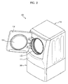
- FIG. 1 is a schematic view showing an internal configuration of a laundry drying apparatus according to the related art in brief.
- the laundry drying apparatus includes a cabinet 20 defining an external appearance of the drying apparatus 10, a drying drum 30 rotatably placed within the cabinet 20, an air supply device 50 that supplies dry air into the drying drum 30 and collects and circulates the air, and a drive unit 40 that supplies and transmits power to the drying drum 30 and the air supply device 50.
- a door 21 is installed to the front side of the cabinet 20 such that an object to be dried, i.e. laundry, is introduced into and removed from the drying drum 30 through the open door 21.
- the door 21 is provided with a door glass 22 to allow a user to view a drying process within the drying drum 30.
- the door glass 22 is configured to protrude inward of the drum 30, in order to prevent laundry inside the drying drum 30 from moving toward the door 21 during drying of laundry.
- the drying drum 30 is a cylindrical drum defining a drying space therein.
- the drying drum 30 has a front opening 31 for introduction and removal of laundry and a rear air supply port 32 through which air is supplied from the air supply device 50.
- the air supply device 50 is located below a front end of the drying drum 30 and is configured to collect and heat air inside the drying drum 30, and thereafter to supply the heated air through a rear end of the drying drum 30.
- the above-described air supply device 50 includes a blowing fan 54 configured to cause movement of air, a collection duct 52 located at the front end of the drying drum 30 to collect air, a heating duct 55 connected to the collection duct 52 to heat air, and a condensation duct 56 connected to the heating duct 55 to condense moisture contained in air.
- the drive unit 40 transmits power for operation of the drying drum 30 as well as the air supply device 50.
- the drive unit 40 includes a motor 41, and a power transmission member 42 (for example, a belt and a pulley) configured to transmit rotational power of the motor 41 to the drying drum 30.
- the blowing fan 54 may be directly connected to the motor 41 to receive power from the motor 41.
- a lint filter 60 is provided in the collection duct 52 of the air supply device 50 and serves to catch lint contained in the air collected from the drying drum 30.
- the lint filter 60 must be located in front of the drying drum 30.
- the lint filter 60 is separably mounted in the collection duct 52.
- the drying drum 30 and the blowing fan 54 are configured to be driven by the single motor 41.
- the drying drum 30 is typically horizontally installed.
- the drying drum 30 is horizontally installed to allow air to uniformly pass through laundry as an object to be dried.
- the door 21 configured to open or close the drying drum 30 is vertically installed to open or close the opening 31 of the drying drum 30.
- the user who tries to introduce or remove laundry must bend at the waist, which may cause user inconvenience.
- the lint filter 60 is located between the horizontally installed drying drum 30 and the vertically installed door 21.
- the door glass 22 of the door 21 may clog an air path extending from the drying drum 30 to the lint filter 60.
- laundry when the drying drum 30 is rotated during drying of laundry, laundry may jam between the door glass 22 and the lint filter 60.
- the jammed laundry may clog an air collection path extending through the collection duct 52 and the lint filter 60, and may prevent rotation of the drying drum 30.
- the present invention is directed to a laundry drying apparatus that substantially obviates one or more problems due to limitation and disadvantages of the related art.
- One object of the present invention is to provide a laundry drying apparatus in which a door of the laundry drying apparatus is tilted to allow a user to bend less at the waist when introducing and removing laundry, which may improve user access to laundry.
- Another object of the present invention is to provide a laundry drying apparatus in which a door of the laundry drying apparatus is tilted to provide an installation space for a lint filter interposed between the door and a drum and to ensure easy separation and coupling of the lint filter.
- a further object of the present invention is to provide a laundry drying apparatus in which a door of the laundry drying apparatus is tilted to achieve a path for a lint filter interposed between the door and a drum.
- a laundry drying apparatus includes a cabinet including a front panel provided with an opening for introduction of laundry, a drying drum horizontally installed within the cabinet, and an air supply device configured to collect air inside the drying drum and supply the air into the drying drum, wherein the front panel includes an upper region where the door for introduction of laundry is installed and a lower region located below the upper region, and wherein the upper region is tilted rearward of the cabinet by a predetermined angle.
- the door installed at the upper region may be tilted by an angle corresponding to the predetermined angle of the upper region.
- the tilting angle of the upper region may be within a range of 10 ⁇ 14 degrees.
- the lower region may be indented inward of the front panel with respect to the upper region, and a seam portion between the upper region and the lower region may protrude forward of the front panel.
- the drying drum may include a cylindrical drum body, a front plate configured to rotatably support a front end of the drum body, and a rear plate configured to rotatably support a rear end of the drum body.
- the front plate may protrude toward the front panel and may have an inclined aperture connected to the opening formed in the cabinet.
- the air supply device may include a collection duct connected to the lower side of the inclined aperture, a blowing fan connected to the collection duct to move air, a heating duct connected to the blowing fan to heat the moved air, and a condensation duct configured to supply the air heated by the heating duct into the drying drum through the rear plate.
- a lint filter mount on which the lint filter is mounted may be formed at the lower side of the inclined aperture.
- the lint filter may be located inside the collection duct when mounted to the lint filter mount.
- An air collector may be formed below the inclined aperture to communicate the drying drum and the lint filter with each other.
- the door may include a door glass protruding toward the drying drum, and an anti-jamming member may be provided inside the inclined aperture to prevent laundry from jamming in a gap between the inclined aperture and the door glass.
- the anti-jamming member may have a crescent shape and may extend from an inner lower portion of the inclined aperture to both sides of an upper portion of the inclined aperture.
- the laundry drying apparatus may further include an auxiliary device provided below the cabinet to raise the height of the cabinet.
- the auxiliary device may include a housing configured to support the cabinet and defining a space therein, and a drawer received in the housing so as to be drawn forward of the cabinet.
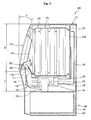
- the laundry drying apparatus As exemplarily shown in FIGs. 2 and 3 , the laundry drying apparatus according to the present invention, designated by reference numeral 100, includes a cabinet 110 defining an external appearance of the apparatus 100 and having a door 114 for introduction and removal of an object to be dried, i.e. laundry, a drying drum 120 rotatably placed within the cabinet 110, an air supply device 140 that supplies heated hot air into the drying drum 120, and a drive unit 130 that supplies rotational power to drive the drying drum 120 and the air supply device 140.
- a cabinet 110 defining an external appearance of the apparatus 100 and having a door 114 for introduction and removal of an object to be dried, i.e. laundry
- a drying drum 120 rotatably placed within the cabinet 110
- an air supply device 140 that supplies heated hot air into the drying drum 120
- a drive unit 130 that supplies rotational power to drive the drying drum 120 and the air supply device 140.
- the laundry drying apparatus 100 may further include an auxiliary device 160 configured to increase the height of the laundry drying apparatus 100.
- the auxiliary device 160 may be configured to allow the laundry drying apparatus 100 to be seated thereon. To this end, the auxiliary device 160 may have a shape corresponding to the external appearance of the laundry drying apparatus 100. The auxiliary device 160 will be described in detail after completing explanation of the laundry drying apparatus 100.
- the cabinet 110 defines the external appearance of the laundry drying apparatus 100.
- the cabinet 110 is constructed by a front panel 111 that defines the front side of the laundry drying apparatus 100, the door 114 being pivotally rotatably coupled to the front panel 111, and lateral panels (not shown), a top panel (not shown), and a rear panel (not shown) which respectively define both lateral sides, top side, and rear side of the cabinet 110.
- the lateral panel, the top panel, and the rear panel have the same configuration as a lateral panel, a top panel, and a rear panel of the related art.
- the front panel 111 has a different configuration from a front panel of the related art.
- the drum 30 is horizontally installed such that the opening 31 of the drum 30 is defined in a vertical plane.
- the door 21 used to open or close the opening 31 of the drum 30 must be vertically installed so as to be pivotally rotated about a vertical axis corresponding to the opening 31 of the drum 30. Therefore, the front panel of the laundry drying apparatus 10 according to the related art is installed in a vertical plane.
- the door 114 coupled to the front panel 111 is tilted by a predetermined angle A.
- the door 114 may be installed by an angle to ensure that an upper portion of the door 114 is tilted rearward of the laundry drying apparatus 100.
- the tilting angle of the door 114 may be within a range of 10 ⁇ 14 degrees, more particularly, about 12 degrees.
- a user may bend less at the waist when introducing or removing laundry as compared to the case in which the door 114 is vertically installed, which may increase user convenience.
- the front panel 111 may be divided into an upper region B where the door 114 is installed, and a lower region C where the door 114 is not installed.
- the upper region B is tilted by the angle A similar to the door 114 in consideration of installation of the door 114 to the upper region B as described above.
- the lower region C located below the upper region B may be vertically defined differently from the upper region B, or may have a symmetrical shape of the upper region B.
- the laundry drying apparatus 100 may have an excessively protruding lower portion, which may make it difficult for the user to access the laundry drying apparatus 100. Therefore, the lower region C may be tilted in a direction opposite to a tilting direction of the upper region B (i.e. may be tilted downward and inward of the laundry drying apparatus 100).
- the front panel 111 of the laundry drying apparatus 100 consists of the upper region B where the door 114 is installed and the lower region C located below the upper region B, a seam portion between the upper region B and the lower region C protrudes outward from the laundry drying apparatus 100, an upper end of the upper region B is tilted inward of the laundry drying apparatus 100, and a lower end of the lower region C is tilted inward of the laundry drying apparatus 100.
- the lower region C may provide a space to allow the user to access the laundry drying apparatus 100, and both the upper region B and the door 114 installed to the upper region B may allow the user to easily introduce and remove laundry.
- the upper region B of the front panel 111 is provided with an opening 112 for introduction of laundry, and the door 114 is coupled to one side of the opening 112.
- the door 114 is provided at the center thereof with a door glass 116 to allow the user to view the interior of the drying drum 120.
- the door glass 116 is configured to protrude inward of the drying drum 120.
- the door 114 installed to the front panel 111 is coupled to the front panel 111 via a hinge device (not shown).
- the hinge device may provide a predetermined magnitude of repulsive elasticity upon opening and closing of the door 114.
- the door 114 may be forcibly rotated by the weight of the door 114 upon opening or closing of the door 114.
- the repulsive elasticity of the hinge device may prevent the door 114 from being forcibly rotated by the weight of the door 114.
- the drying drum 120 is rotatably placed within the cabinet 110.
- the drying drum 120 includes a rotatably supported cylindrical drum body 121, a front plate 122 coupled to a front end of the drum body 121 to rotatably support the front end of the drum body 121, and a rear plate 129 coupled to a rear end of the drum body 121 to rotatably support the rear end of the drum body 121.
- the front plate 122 of the drying drum 120 serves to connect the drum body 121 to the opening 112 of the front panel 111.
- the front panel 111 is tilted by the predetermined angle A as described above, whereas the front end of the drum body 121 of the drying drum 120 is defined in a vertical plane.
- the top of the opening 112 of the front panel 111 is located proximate to the top of the front end of the drum body 121, whereas the bottom of the opening 112 of the front panel 111 is spaced apart from the bottom of the front end of the drum body 121 by a predetermined distance. That is, the opening 112 of the front panel 111 and the front end of the drum body 121 are spaced apart from each other in a non-parallel state.
- one surface of the front plate 122 that faces the drum body 121 defines a vertical surface corresponding to the drum body 121 so as to rotatably support the drum body 121, whereas the other surface of the front plate 122 that faces the front panel 111 is a obliquely protruding surface having the predetermined inclination angle A.
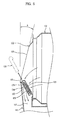
- the front plate 122 takes the form of a conical plate, the center of which protrudes toward the front panel 111, and is provided at a pointed end thereof with an inclined aperture 123 that comes into contact with the opening 112 of the front panel 111.
- a lint filter mount 124 on which a lint filter 150 that will be described hereinafter is mounted, is formed at a lower portion of an inner surface of the inclined aperture 123.
- a collection duct 141 of the air supply device 140 that will be described hereinafter is connected to a position below and at the outside of the inclined aperture 123. The lint filter 150 and the air supply device 140 will be described in detail later.
- the lint filter 150 mounted on the lint filter mount 124 is upwardly exposed. Thereby, as air inside the drying drum 120 is moved into the collection duct 141 by way of the lint filter 150, lint contained in the air is caught by the lint filter 150.
- the lint filter 150 includes a housing defining a space therein, and a filter 154 located inside the housing.
- the housing has a top inlet 151 and a lateral inlet 152 respectively formed in a top surface and one lateral surface thereof for introduction of air inside the drying drum 120, and an outlet 153 formed in the other lateral surface thereof for discharge of air filtered by the filter 154.
- the above-described lint filter 150 is separably mounted to the lint filter mount 124 of the front plate 122, and is obliquely installed by a predetermined angle so as to be removed through the inclined aperture 123.
- An air collector 125 in the form of a plurality of through-holes may further be formed in the front plate 122 at a position proximate to the lint filter mount 124 to guide introduction of air inside the drying drum 120 into the lateral inlet 152 of the lint filter 150. Provision of the air collector 125 may increase the quantity of air to be introduced into the lint filter 150, thereby enhancing filtering efficiency of the lint filter 150.
- the inclined aperture 123 of the front plate 122 is indented toward the door 114, and the door glass 116 of the door 114 protrudes from the inclined aperture 123 into the drying drum 120.
- a circular or elliptical gap D is defined between an inner peripheral surface of the inclined aperture 123 and an outer peripheral surface of the door glass 116.
- the gap D between an inner upper portion of the inclined aperture 123 and an upper portion of the door glass 116 is relatively small, and the gap D between an inner lower portion of the inclined aperture 123 and a lower portion of the door glass 116 is relatively large.
- the gap D between the inner peripheral surface of the inclined aperture 123 and the door glass 116 may cause laundry to jam between the inner peripheral surface of the inclined aperture 123 and the door glass 116 during rotation of the drying drum 120, which may prevent efficient rotation of the laundry. Inefficient rotation of the laundry prevents air supplied into the drying drum 120 from efficiently coming into contact with the laundry, resulting in insufficient drying of the laundry.
- the gap D between the inner upper portion of the inclined aperture 123 and the upper portion of the door glass 116 is relatively small, and the laundry may be easily released from the relatively small gap D by the weight of the laundry.
- the gap D between the inner lower portion of the inclined aperture 123 and the lower portion of the door glass 116 it is necessary to prevent jamming of the laundry because the laundry tends to be collected on the bottom of the drying drum 120 due to gravity.
- an anti-jamming member 126 may be provided at the inner lower portion of the inclined aperture 123 to prevent laundry from jamming between the inner lower portion of the inclined aperture 123 and the lower portion of the door glass 116.
- the anti-jamming member 126 is installed to a lower portion of the inner peripheral surface of the inclined aperture 123 to reduce the gap D between the inner lower portion of the inclined aperture 123 and the lower portion of the door glass 116, thereby preventing laundry from jamming between the inner lower portion of the inclined aperture 123 and the lower portion of the door glass 116.
- the anti-jamming member 126 will hereinafter be described with reference to FIG. 6 .
- one surface of the anti-jamming member 126 has a shape corresponding to the shape of the inner lower portion of the inclined aperture 123 and the other surface of the anti-jamming member 126 is an inclined surface that is relatively similar to a vertical surface.
- the anti-jamming member 126 has a shape having a wide lower end and the width of the anti-jamming member 126 is gradually reduced toward both sides of an upper end thereof. More specifically, the anti-jamming member 126 has a crescent shape.
- the anti-jamming member 126 centrally has a plurality of through-holes 127 that may communicate with the air collector 125 formed at the inclined aperture 123. Both lateral sides of the anti-jamming member 126 are provided with extensions 128 which protrude along both lateral sides of the inner peripheral surface of the inclined aperture 123.
- the rear plate 129 of the drying drum 120 serves not only to rotatably support the rear end of the drum body 121, but also to supply air supplied from the air supply device 140 into the drum body 121.
- the rear plate 129 has a plurality of air supply holes 129a formed in a predetermined portion thereof, and a condensation duct 146 of the air supply device 140 is installed at the outside of the rear plate 129 to communicate with the air supply holes 129a for supply of air.
- a front support member (not shown) and a rear support member (not shown), are respectively provided at inner surfaces of the front plate 122 and the rear plate 129 opposite to each other.
- the front support member and the rear support member take the form of rollers to rotatably support the drum body 121 located between the front plate 122 and the rear plate 129.
- Various embodiments of the front support member and the rear support member may be proposed, and a detailed description of this is omitted herein.
- the drive unit 130 serves to drive the drum body 121 of the drying drum 120 and a blowing fan 143 of the air supply device 140 that will be described hereinafter.
- the drive unit 130 includes a motor 132 to provide rotational power.
- the blowing fan 143 of the air supply device 140 is connected to one end of a rotating shaft of the motor 132, and a pulley 134 is provided at the other end of the rotating shaft to transmit rotational power to the drying drum 120.
- the pulley 134 and the drum body 121 of the drying drum 120 are connected to each other via a belt 136 and are adapted to receive rotational power of the motor 132.
- the drum body 121 of the drying drum 120 and the blowing fan 143 of the air supply device 140 may be operated in linkage to each other.
- the drying drum 120 and the blowing fan 143 may be driven individually using different motors.
- Various embodiments of the drive unit 130 may be proposed, and thus a detailed description of this is omitted herein.
- the air supply device 140 serves to collect and heat air inside the drying drum 120 and supply the heated air into the drying drum 120.
- the air supply device 140 includes the collection duct 141 connected to the front plate 122 of the drying drum 120 to collect air inside the drying drum 120, the blowing fan 143 connected to the collection duct 141 to move air, a heating duct 144 in which a heater (not shown) to heat the air moved by the blowing fan 143 is provided, and the condensation duct 146 that condenses moisture of the air heated in the heating duct 144 to generate heated dry air and guide the same into the drying drum 120.
- the collection duct 141 is connected to an outer lower portion of the front plate 122 of the drying drum 120. More specifically, the collection duct 141 is connected to a portion below the lint filter mount 124 provided at the inclined aperture 123. Accordingly, the collection duct 141 provides a lint filter space 142 in which the lint filter 150 mounted to the lint filter mount 124 is received.
- an exhaust type air supply device may be applied to the present invention.
- an air supply device using the heater has been described above, an air supply device using a heat pump that heats air using refrigerant may be applied to the present invention.
- the auxiliary device 160 serves to raise the height of the laundry drying apparatus 100 in order to provide the laundry drying apparatus 100 with enhanced user convenience.
- the auxiliary device 160 includes a housing 162 that is configured to support the laundry drying apparatus 100 and defines an inner space, and a drawer 164 provided inside the housing 162 so as to be drawn forward of the laundry drying apparatus 100.
- a washing device (not shown) for washing laundry may be provided in the drawer 164.
- the drawer 146 may provide a separate drying space.
- Various embodiments of the auxiliary device 160 may be proposed, and thus a detailed description of this is omitted herein.
- a door of the laundry drying apparatus is tilted to improve user access to laundry so as to allow the user to bend less at the waist when introducing and removing laundry, which results in enhanced user convenience.
- a door of the laundry drying apparatus is tilted and a lint filter is mounted in a space between a lower portion of the door and a drum, which enables easy separation and coupling of the lint filter.
- a door of the laundry drying apparatus is tilted and a lint filter is mounted in a space between a lower portion of the door and a drum, which ensures a greater path of air to be introduced into the lint filter, resulting in reduced air resistance in the path.
Landscapes
- Engineering & Computer Science (AREA)
- Textile Engineering (AREA)
- Detail Structures Of Washing Machines And Dryers (AREA)
Applications Claiming Priority (1)
| Application Number | Priority Date | Filing Date | Title |
|---|---|---|---|
| KR1020130083684A KR102086508B1 (ko) | 2013-07-16 | 2013-07-16 | 의류 건조장치 |
Publications (2)
| Publication Number | Publication Date |
|---|---|
| EP2829653A1 true EP2829653A1 (de) | 2015-01-28 |
| EP2829653B1 EP2829653B1 (de) | 2020-01-08 |
Family
ID=50064508
Family Applications (1)
| Application Number | Title | Priority Date | Filing Date |
|---|---|---|---|
| EP14154320.7A Active EP2829653B1 (de) | 2013-07-16 | 2014-02-07 | Wäschetrocknungsvorrichtung |
Country Status (5)
| Country | Link |
|---|---|
| US (1) | US9885145B2 (de) |
| EP (1) | EP2829653B1 (de) |
| KR (1) | KR102086508B1 (de) |
| CN (1) | CN104294566B (de) |
| AU (1) | AU2014200313B2 (de) |
Cited By (1)
| Publication number | Priority date | Publication date | Assignee | Title |
|---|---|---|---|---|
| CN112088231A (zh) * | 2018-05-08 | 2020-12-15 | Lg电子株式会社 | 衣物处理装置 |
Families Citing this family (12)
| Publication number | Priority date | Publication date | Assignee | Title |
|---|---|---|---|---|
| CN106381656A (zh) * | 2016-10-31 | 2017-02-08 | 无锡小天鹅股份有限公司 | 衣物处理装置 |
| CN106637878B (zh) * | 2016-12-30 | 2018-06-19 | 无锡小天鹅股份有限公司 | 干衣机的风道组件和具有其的干衣机 |
| JP7108398B2 (ja) * | 2017-01-25 | 2022-07-28 | 三星電子株式会社 | 衣類乾燥機 |
| CN109487482B (zh) * | 2017-09-13 | 2025-03-04 | 青岛海尔洗涤电器有限公司 | 一种衣物处理设备 |
| KR102436958B1 (ko) * | 2017-09-19 | 2022-08-29 | 삼성전자주식회사 | 건조기 |
| US10765974B2 (en) * | 2019-01-25 | 2020-09-08 | Haier Us Appliance Solutions, Inc. | Lint collection assembly for a dryer appliance |
| KR102822999B1 (ko) * | 2020-03-03 | 2025-06-18 | 엘지전자 주식회사 | 세탁물 건조기 |
| CN111218807B (zh) * | 2020-03-10 | 2020-11-17 | 义乌市华邦服饰有限公司 | 一种衣物旋转烘干设备 |
| CN114318813B (zh) * | 2020-09-30 | 2024-10-29 | 青岛海尔洗衣机有限公司 | 干衣机 |
| US11807973B2 (en) * | 2020-11-10 | 2023-11-07 | Whirlpool Corporation | Combination washer/dryer with a lint screen |
| CN116412659B (zh) * | 2023-03-28 | 2024-10-18 | 浙江百盛光电股份有限公司 | 一种无尘洁净烘箱高风量进风系统 |
| WO2025135859A1 (ko) * | 2023-12-22 | 2025-06-26 | 엘지전자 주식회사 | 의류처리장치 |
Citations (7)
| Publication number | Priority date | Publication date | Assignee | Title |
|---|---|---|---|---|
| US2813414A (en) * | 1955-05-27 | 1957-11-19 | Westinghouse Electric Corp | Apparatus for washing and drying fabrics |
| DE3213420A1 (de) * | 1982-04-10 | 1983-10-13 | Wilhelm Dr.-Ing. 5340 Bad Honnef Lepper | Waschmaschine, waschtrockner und waeschetrockner mit untergestell |
| FR2736942A1 (fr) * | 1995-07-21 | 1997-01-24 | Ciapem | Lave-linge ou seche-linge a chargement frontal |
| US20040159009A1 (en) * | 2002-12-02 | 2004-08-19 | Hwang Sung Gi | Laundry dryer |
| US20110265524A1 (en) * | 2010-04-30 | 2011-11-03 | Lg Electronics Inc. | Laundry apparatus |
| EP2423375A1 (de) * | 2010-08-24 | 2012-02-29 | Electrolux Home Products Corporation N.V. | Waschmaschine mit Drehtrommel |
| EP2610391A1 (de) * | 2011-12-28 | 2013-07-03 | Electrolux Home Products Corporation N.V. | Wäschetrockner-Haushaltsgerät mit Dampfdüseneinheit |
Family Cites Families (13)
| Publication number | Priority date | Publication date | Assignee | Title |
|---|---|---|---|---|
| US4665628A (en) * | 1986-03-31 | 1987-05-19 | Raytheon Company | Recuperative clothes dryer with enhanced recirculation and air flow |
| KR100813041B1 (ko) * | 2001-09-05 | 2008-03-14 | 엘지전자 주식회사 | 드럼세탁기의 도어와 드럼 사이의 세탁물 끼임 방지구조 |
| JP4679352B2 (ja) * | 2005-11-25 | 2011-04-27 | 株式会社東芝 | 衣類乾燥機 |
| US7913419B2 (en) * | 2005-12-30 | 2011-03-29 | Whirlpool Corporation | Non-tumble clothes dryer |
| KR100710315B1 (ko) | 2006-07-25 | 2007-04-24 | 엘지전자 주식회사 | 보조 의류 처리 장치 및 이를 포함하는 복합 의류 처리장치 |
| KR101265623B1 (ko) * | 2006-08-22 | 2013-05-22 | 엘지전자 주식회사 | 피티시 히터를 이용하는 페데스탈 건조기 |
| KR101070536B1 (ko) | 2008-12-17 | 2011-10-05 | 엘지전자 주식회사 | 건조기 및 건조기의 이물질 제거 장치 및 건조기의 제어 방법 |
| US8631527B2 (en) * | 2009-08-10 | 2014-01-21 | Whirlpool Corporation | Laundry treating appliance with tumble pattern control |
| DE212011100095U1 (de) | 2010-05-07 | 2013-01-11 | Lg Electronics Inc. | Kleidungsbehandlungsvorrichtung und Filtertechnologie |
| US8387274B2 (en) | 2010-07-16 | 2013-03-05 | Whirlpool Corporation | Variable airflow in laundry dryer having variable air inlet |
| KR20120066549A (ko) * | 2010-12-14 | 2012-06-22 | 삼성전자주식회사 | 의류 건조기 |
| JP5492137B2 (ja) | 2011-04-19 | 2014-05-14 | 日立アプライアンス株式会社 | ドラム式洗濯乾燥機 |
| US8875416B2 (en) * | 2012-04-24 | 2014-11-04 | Whirlpool Corporation | Laundry treating appliance door with planar window element and projection |
-
2013
- 2013-07-16 KR KR1020130083684A patent/KR102086508B1/ko active Active
-
2014
- 2014-01-15 US US14/155,983 patent/US9885145B2/en active Active
- 2014-01-17 AU AU2014200313A patent/AU2014200313B2/en active Active
- 2014-01-23 CN CN201410032225.5A patent/CN104294566B/zh active Active
- 2014-02-07 EP EP14154320.7A patent/EP2829653B1/de active Active
Patent Citations (7)
| Publication number | Priority date | Publication date | Assignee | Title |
|---|---|---|---|---|
| US2813414A (en) * | 1955-05-27 | 1957-11-19 | Westinghouse Electric Corp | Apparatus for washing and drying fabrics |
| DE3213420A1 (de) * | 1982-04-10 | 1983-10-13 | Wilhelm Dr.-Ing. 5340 Bad Honnef Lepper | Waschmaschine, waschtrockner und waeschetrockner mit untergestell |
| FR2736942A1 (fr) * | 1995-07-21 | 1997-01-24 | Ciapem | Lave-linge ou seche-linge a chargement frontal |
| US20040159009A1 (en) * | 2002-12-02 | 2004-08-19 | Hwang Sung Gi | Laundry dryer |
| US20110265524A1 (en) * | 2010-04-30 | 2011-11-03 | Lg Electronics Inc. | Laundry apparatus |
| EP2423375A1 (de) * | 2010-08-24 | 2012-02-29 | Electrolux Home Products Corporation N.V. | Waschmaschine mit Drehtrommel |
| EP2610391A1 (de) * | 2011-12-28 | 2013-07-03 | Electrolux Home Products Corporation N.V. | Wäschetrockner-Haushaltsgerät mit Dampfdüseneinheit |
Cited By (3)
| Publication number | Priority date | Publication date | Assignee | Title |
|---|---|---|---|---|
| CN112088231A (zh) * | 2018-05-08 | 2020-12-15 | Lg电子株式会社 | 衣物处理装置 |
| EP3792389A4 (de) * | 2018-05-08 | 2022-02-16 | LG Electronics Inc. | Wäschebehandlungsvorrichtung |
| US12331450B2 (en) | 2018-05-08 | 2025-06-17 | Lg Electronics Inc. | Clothes processing apparatus |
Also Published As
| Publication number | Publication date |
|---|---|
| AU2014200313A1 (en) | 2015-02-05 |
| KR20150009326A (ko) | 2015-01-26 |
| US9885145B2 (en) | 2018-02-06 |
| US20150020399A1 (en) | 2015-01-22 |
| EP2829653B1 (de) | 2020-01-08 |
| CN104294566A (zh) | 2015-01-21 |
| KR102086508B1 (ko) | 2020-03-09 |
| AU2014200313B2 (en) | 2015-11-26 |
| CN104294566B (zh) | 2017-03-01 |
Similar Documents
| Publication | Publication Date | Title |
|---|---|---|
| EP2829653B1 (de) | Wäschetrocknungsvorrichtung | |
| EP3360999A1 (de) | Trocknungsvorrichtung sowie wasch- und wäschetrocknermaschine damit | |
| EP2699723B1 (de) | Waschmaschine | |
| KR20120134369A (ko) | 의류처리장치 | |
| KR101241915B1 (ko) | 건조기 | |
| KR101319881B1 (ko) | 복합 의류 처리 장치 | |
| EP3040471A1 (de) | Wäschetrocknungsvorrichtung | |
| KR101191211B1 (ko) | 건조기의 제어방법 | |
| KR101314625B1 (ko) | 의류처리장치 | |
| KR101191210B1 (ko) | 건조기 | |
| KR101685977B1 (ko) | 건조기 | |
| KR20150118859A (ko) | 건조기 | |
| KR101253193B1 (ko) | 건조기 | |
| KR20110123333A (ko) | 건조기 | |
| KR20110123346A (ko) | 건조기 | |
| KR101191208B1 (ko) | 건조기 | |
| EP3943656B1 (de) | Wäschebehandlungsvorrichtung | |
| KR101177479B1 (ko) | 건조기 | |
| KR101663523B1 (ko) | 세탁물 처리장치 | |
| US20250171948A1 (en) | Clothing dryer including filter assembly | |
| KR101191207B1 (ko) | 건조기 | |
| KR102848913B1 (ko) | 의류처리장치 | |
| KR101191212B1 (ko) | 세탁장치 | |
| KR20120008645A (ko) | 건조장치 | |
| KR20120070765A (ko) | 건조기 |
Legal Events
| Date | Code | Title | Description |
|---|---|---|---|
| 17P | Request for examination filed |
Effective date: 20140303 |
|
| AK | Designated contracting states |
Kind code of ref document: A1 Designated state(s): AL AT BE BG CH CY CZ DE DK EE ES FI FR GB GR HR HU IE IS IT LI LT LU LV MC MK MT NL NO PL PT RO RS SE SI SK SM TR |
|
| AX | Request for extension of the european patent |
Extension state: BA ME |
|
| PUAI | Public reference made under article 153(3) epc to a published international application that has entered the european phase |
Free format text: ORIGINAL CODE: 0009012 |
|
| RBV | Designated contracting states (corrected) |
Designated state(s): AL AT BE BG CH CY CZ DE DK EE ES FI FR GB GR HR HU IE IS IT LI LT LU LV MC MK MT NL NO PL PT RO RS SE SI SK SM TR |
|
| STAA | Information on the status of an ep patent application or granted ep patent |
Free format text: STATUS: EXAMINATION IS IN PROGRESS |
|
| 17Q | First examination report despatched |
Effective date: 20180704 |
|
| GRAP | Despatch of communication of intention to grant a patent |
Free format text: ORIGINAL CODE: EPIDOSNIGR1 |
|
| STAA | Information on the status of an ep patent application or granted ep patent |
Free format text: STATUS: GRANT OF PATENT IS INTENDED |
|
| INTG | Intention to grant announced |
Effective date: 20190828 |
|
| GRAS | Grant fee paid |
Free format text: ORIGINAL CODE: EPIDOSNIGR3 |
|
| GRAA | (expected) grant |
Free format text: ORIGINAL CODE: 0009210 |
|
| STAA | Information on the status of an ep patent application or granted ep patent |
Free format text: STATUS: THE PATENT HAS BEEN GRANTED |
|
| AK | Designated contracting states |
Kind code of ref document: B1 Designated state(s): AL AT BE BG CH CY CZ DE DK EE ES FI FR GB GR HR HU IE IS IT LI LT LU LV MC MK MT NL NO PL PT RO RS SE SI SK SM TR |
|
| REG | Reference to a national code |
Ref country code: GB Ref legal event code: FG4D |
|
| REG | Reference to a national code |
Ref country code: CH Ref legal event code: EP |
|
| REG | Reference to a national code |
Ref country code: DE Ref legal event code: R096 Ref document number: 602014059575 Country of ref document: DE |
|
| REG | Reference to a national code |
Ref country code: IE Ref legal event code: FG4D |
|
| REG | Reference to a national code |
Ref country code: AT Ref legal event code: REF Ref document number: 1222844 Country of ref document: AT Kind code of ref document: T Effective date: 20200215 |
|
| REG | Reference to a national code |
Ref country code: NL Ref legal event code: MP Effective date: 20200108 |
|
| REG | Reference to a national code |
Ref country code: LT Ref legal event code: MG4D |
|
| PG25 | Lapsed in a contracting state [announced via postgrant information from national office to epo] |
Ref country code: LT Free format text: LAPSE BECAUSE OF FAILURE TO SUBMIT A TRANSLATION OF THE DESCRIPTION OR TO PAY THE FEE WITHIN THE PRESCRIBED TIME-LIMIT Effective date: 20200108 Ref country code: NO Free format text: LAPSE BECAUSE OF FAILURE TO SUBMIT A TRANSLATION OF THE DESCRIPTION OR TO PAY THE FEE WITHIN THE PRESCRIBED TIME-LIMIT Effective date: 20200408 Ref country code: NL Free format text: LAPSE BECAUSE OF FAILURE TO SUBMIT A TRANSLATION OF THE DESCRIPTION OR TO PAY THE FEE WITHIN THE PRESCRIBED TIME-LIMIT Effective date: 20200108 Ref country code: FI Free format text: LAPSE BECAUSE OF FAILURE TO SUBMIT A TRANSLATION OF THE DESCRIPTION OR TO PAY THE FEE WITHIN THE PRESCRIBED TIME-LIMIT Effective date: 20200108 Ref country code: PT Free format text: LAPSE BECAUSE OF FAILURE TO SUBMIT A TRANSLATION OF THE DESCRIPTION OR TO PAY THE FEE WITHIN THE PRESCRIBED TIME-LIMIT Effective date: 20200531 Ref country code: RS Free format text: LAPSE BECAUSE OF FAILURE TO SUBMIT A TRANSLATION OF THE DESCRIPTION OR TO PAY THE FEE WITHIN THE PRESCRIBED TIME-LIMIT Effective date: 20200108 |
|
| PG25 | Lapsed in a contracting state [announced via postgrant information from national office to epo] |
Ref country code: IS Free format text: LAPSE BECAUSE OF FAILURE TO SUBMIT A TRANSLATION OF THE DESCRIPTION OR TO PAY THE FEE WITHIN THE PRESCRIBED TIME-LIMIT Effective date: 20200508 Ref country code: GR Free format text: LAPSE BECAUSE OF FAILURE TO SUBMIT A TRANSLATION OF THE DESCRIPTION OR TO PAY THE FEE WITHIN THE PRESCRIBED TIME-LIMIT Effective date: 20200409 Ref country code: HR Free format text: LAPSE BECAUSE OF FAILURE TO SUBMIT A TRANSLATION OF THE DESCRIPTION OR TO PAY THE FEE WITHIN THE PRESCRIBED TIME-LIMIT Effective date: 20200108 Ref country code: LV Free format text: LAPSE BECAUSE OF FAILURE TO SUBMIT A TRANSLATION OF THE DESCRIPTION OR TO PAY THE FEE WITHIN THE PRESCRIBED TIME-LIMIT Effective date: 20200108 Ref country code: SE Free format text: LAPSE BECAUSE OF FAILURE TO SUBMIT A TRANSLATION OF THE DESCRIPTION OR TO PAY THE FEE WITHIN THE PRESCRIBED TIME-LIMIT Effective date: 20200108 Ref country code: BG Free format text: LAPSE BECAUSE OF FAILURE TO SUBMIT A TRANSLATION OF THE DESCRIPTION OR TO PAY THE FEE WITHIN THE PRESCRIBED TIME-LIMIT Effective date: 20200408 |
|
| REG | Reference to a national code |
Ref country code: CH Ref legal event code: PL |
|
| REG | Reference to a national code |
Ref country code: DE Ref legal event code: R097 Ref document number: 602014059575 Country of ref document: DE |
|
| REG | Reference to a national code |
Ref country code: BE Ref legal event code: MM Effective date: 20200229 |
|
| PG25 | Lapsed in a contracting state [announced via postgrant information from national office to epo] |
Ref country code: DK Free format text: LAPSE BECAUSE OF FAILURE TO SUBMIT A TRANSLATION OF THE DESCRIPTION OR TO PAY THE FEE WITHIN THE PRESCRIBED TIME-LIMIT Effective date: 20200108 Ref country code: EE Free format text: LAPSE BECAUSE OF FAILURE TO SUBMIT A TRANSLATION OF THE DESCRIPTION OR TO PAY THE FEE WITHIN THE PRESCRIBED TIME-LIMIT Effective date: 20200108 Ref country code: SM Free format text: LAPSE BECAUSE OF FAILURE TO SUBMIT A TRANSLATION OF THE DESCRIPTION OR TO PAY THE FEE WITHIN THE PRESCRIBED TIME-LIMIT Effective date: 20200108 Ref country code: ES Free format text: LAPSE BECAUSE OF FAILURE TO SUBMIT A TRANSLATION OF THE DESCRIPTION OR TO PAY THE FEE WITHIN THE PRESCRIBED TIME-LIMIT Effective date: 20200108 Ref country code: RO Free format text: LAPSE BECAUSE OF FAILURE TO SUBMIT A TRANSLATION OF THE DESCRIPTION OR TO PAY THE FEE WITHIN THE PRESCRIBED TIME-LIMIT Effective date: 20200108 Ref country code: CZ Free format text: LAPSE BECAUSE OF FAILURE TO SUBMIT A TRANSLATION OF THE DESCRIPTION OR TO PAY THE FEE WITHIN THE PRESCRIBED TIME-LIMIT Effective date: 20200108 Ref country code: MC Free format text: LAPSE BECAUSE OF FAILURE TO SUBMIT A TRANSLATION OF THE DESCRIPTION OR TO PAY THE FEE WITHIN THE PRESCRIBED TIME-LIMIT Effective date: 20200108 Ref country code: SK Free format text: LAPSE BECAUSE OF FAILURE TO SUBMIT A TRANSLATION OF THE DESCRIPTION OR TO PAY THE FEE WITHIN THE PRESCRIBED TIME-LIMIT Effective date: 20200108 Ref country code: LU Free format text: LAPSE BECAUSE OF NON-PAYMENT OF DUE FEES Effective date: 20200207 |
|
| PLBE | No opposition filed within time limit |
Free format text: ORIGINAL CODE: 0009261 |
|
| STAA | Information on the status of an ep patent application or granted ep patent |
Free format text: STATUS: NO OPPOSITION FILED WITHIN TIME LIMIT |
|
| REG | Reference to a national code |
Ref country code: AT Ref legal event code: MK05 Ref document number: 1222844 Country of ref document: AT Kind code of ref document: T Effective date: 20200108 |
|
| PG25 | Lapsed in a contracting state [announced via postgrant information from national office to epo] |
Ref country code: CH Free format text: LAPSE BECAUSE OF NON-PAYMENT OF DUE FEES Effective date: 20200229 Ref country code: LI Free format text: LAPSE BECAUSE OF NON-PAYMENT OF DUE FEES Effective date: 20200229 |
|
| 26N | No opposition filed |
Effective date: 20201009 |
|
| PG25 | Lapsed in a contracting state [announced via postgrant information from national office to epo] |
Ref country code: IT Free format text: LAPSE BECAUSE OF FAILURE TO SUBMIT A TRANSLATION OF THE DESCRIPTION OR TO PAY THE FEE WITHIN THE PRESCRIBED TIME-LIMIT Effective date: 20200108 Ref country code: FR Free format text: LAPSE BECAUSE OF NON-PAYMENT OF DUE FEES Effective date: 20200308 Ref country code: IE Free format text: LAPSE BECAUSE OF NON-PAYMENT OF DUE FEES Effective date: 20200207 Ref country code: AT Free format text: LAPSE BECAUSE OF FAILURE TO SUBMIT A TRANSLATION OF THE DESCRIPTION OR TO PAY THE FEE WITHIN THE PRESCRIBED TIME-LIMIT Effective date: 20200108 |
|
| PG25 | Lapsed in a contracting state [announced via postgrant information from national office to epo] |
Ref country code: BE Free format text: LAPSE BECAUSE OF NON-PAYMENT OF DUE FEES Effective date: 20200229 Ref country code: PL Free format text: LAPSE BECAUSE OF FAILURE TO SUBMIT A TRANSLATION OF THE DESCRIPTION OR TO PAY THE FEE WITHIN THE PRESCRIBED TIME-LIMIT Effective date: 20200108 Ref country code: SI Free format text: LAPSE BECAUSE OF FAILURE TO SUBMIT A TRANSLATION OF THE DESCRIPTION OR TO PAY THE FEE WITHIN THE PRESCRIBED TIME-LIMIT Effective date: 20200108 |
|
| GBPC | Gb: european patent ceased through non-payment of renewal fee |
Effective date: 20200408 |
|
| PG25 | Lapsed in a contracting state [announced via postgrant information from national office to epo] |
Ref country code: GB Free format text: LAPSE BECAUSE OF NON-PAYMENT OF DUE FEES Effective date: 20200408 |
|
| PG25 | Lapsed in a contracting state [announced via postgrant information from national office to epo] |
Ref country code: TR Free format text: LAPSE BECAUSE OF FAILURE TO SUBMIT A TRANSLATION OF THE DESCRIPTION OR TO PAY THE FEE WITHIN THE PRESCRIBED TIME-LIMIT Effective date: 20200108 Ref country code: MT Free format text: LAPSE BECAUSE OF FAILURE TO SUBMIT A TRANSLATION OF THE DESCRIPTION OR TO PAY THE FEE WITHIN THE PRESCRIBED TIME-LIMIT Effective date: 20200108 Ref country code: CY Free format text: LAPSE BECAUSE OF FAILURE TO SUBMIT A TRANSLATION OF THE DESCRIPTION OR TO PAY THE FEE WITHIN THE PRESCRIBED TIME-LIMIT Effective date: 20200108 |
|
| PG25 | Lapsed in a contracting state [announced via postgrant information from national office to epo] |
Ref country code: MK Free format text: LAPSE BECAUSE OF FAILURE TO SUBMIT A TRANSLATION OF THE DESCRIPTION OR TO PAY THE FEE WITHIN THE PRESCRIBED TIME-LIMIT Effective date: 20200108 Ref country code: AL Free format text: LAPSE BECAUSE OF FAILURE TO SUBMIT A TRANSLATION OF THE DESCRIPTION OR TO PAY THE FEE WITHIN THE PRESCRIBED TIME-LIMIT Effective date: 20200108 |
|
| PGFP | Annual fee paid to national office [announced via postgrant information from national office to epo] |
Ref country code: DE Payment date: 20250106 Year of fee payment: 12 |