EP2829388A1 - Dispositif de fabrication de tubes ainsi que procédé de fabrication d'un tube - Google Patents
Dispositif de fabrication de tubes ainsi que procédé de fabrication d'un tube Download PDFInfo
- Publication number
- EP2829388A1 EP2829388A1 EP13178093.4A EP13178093A EP2829388A1 EP 2829388 A1 EP2829388 A1 EP 2829388A1 EP 13178093 A EP13178093 A EP 13178093A EP 2829388 A1 EP2829388 A1 EP 2829388A1
- Authority
- EP
- European Patent Office
- Prior art keywords
- tube
- individual patterns
- feed direction
- data
- cutting
- Prior art date
- Legal status (The legal status is an assumption and is not a legal conclusion. Google has not performed a legal analysis and makes no representation as to the accuracy of the status listed.)
- Granted
Links
Images
Classifications
-
- B—PERFORMING OPERATIONS; TRANSPORTING
- B29—WORKING OF PLASTICS; WORKING OF SUBSTANCES IN A PLASTIC STATE IN GENERAL
- B29D—PRODUCING PARTICULAR ARTICLES FROM PLASTICS OR FROM SUBSTANCES IN A PLASTIC STATE
- B29D23/00—Producing tubular articles
- B29D23/20—Flexible squeeze tubes, e.g. for cosmetics
-
- B—PERFORMING OPERATIONS; TRANSPORTING
- B26—HAND CUTTING TOOLS; CUTTING; SEVERING
- B26D—CUTTING; DETAILS COMMON TO MACHINES FOR PERFORATING, PUNCHING, CUTTING-OUT, STAMPING-OUT OR SEVERING
- B26D3/00—Cutting work characterised by the nature of the cut made; Apparatus therefor
- B26D3/16—Cutting rods or tubes transversely
-
- B—PERFORMING OPERATIONS; TRANSPORTING
- B26—HAND CUTTING TOOLS; CUTTING; SEVERING
- B26D—CUTTING; DETAILS COMMON TO MACHINES FOR PERFORATING, PUNCHING, CUTTING-OUT, STAMPING-OUT OR SEVERING
- B26D5/00—Arrangements for operating and controlling machines or devices for cutting, cutting-out, stamping-out, punching, perforating, or severing by means other than cutting
- B26D5/20—Arrangements for operating and controlling machines or devices for cutting, cutting-out, stamping-out, punching, perforating, or severing by means other than cutting with interrelated action between the cutting member and work feed
- B26D5/30—Arrangements for operating and controlling machines or devices for cutting, cutting-out, stamping-out, punching, perforating, or severing by means other than cutting with interrelated action between the cutting member and work feed having the cutting member controlled by scanning a record carrier
Definitions
- the invention relates to a tube manufacturing apparatus according to the preamble of the main claim. Furthermore, the present invention relates to a method for producing a tube according to the preamble of patent claim 7.
- the object of the present invention is therefore to improve a generic tube manufacturing device with respect to the functionality of the control means for triggering the cutting process or to activate the cutting means so that on the one hand separate, potentially optically disturbing markings on or in the single pattern are not required, but at the same time only from the single pattern a fast, the continuous production process is not slowing detection of the individual pattern or the gap is made possible as a basis for triggering the cutting process. Furthermore, a correspondingly improved method for producing a (packaging) tube is to be created.
- control means are located in an optical detector unit which has only a limited transverse extent effective for the detection with respect to a feed direction of the (continuous) tube tube, in the context of the present invention and with reference to a maximum width of the individual patterns Transverse extension is not more than 10%, preferably not more than 2%.
- the optical detector unit according to the invention then only scans, in the manner of a line or stripe image, an elongate section of the single pattern which runs parallel to the feed direction. Accordingly minimized or limited so that both the hardware cost, as well as a computational effort required for data processing:
- the optical detector unit with a correspondingly narrow detector transverse extent much easier and cheaper to realize, as well as a correspondingly reduced to be stored and correlated
- Data amount of the line or strip-shaped section is significantly less than the data amount of a frame capture of the individual patterns.
- the sampled first or second detector data and / or the reference data according to the invention have at least 100, preferably at least 500, more preferably at least 1000 individual values within a period (i.e., between the identical individual patterns following one another according to the invention).
- the computational outlay would be increased by this further development measure, at the same time the correlation according to the invention with this large number of individual values, with high detection reliability, also enables noisy or ambiguous or diffuse signals - as they occur in particular in an application according to the invention without dedicated print marks - reliably recognize and trigger according to the cutting process according to the invention.
- the invention provided in the control means comparison or correlation means also reach on the basis of this narrow section a sufficient detection and detection accuracy with respect to a current position along the feed direction.
- the detection signal of the first detector data recorded according to the invention as a continuous signal is then correlated in an otherwise known manner with the correspondingly treated second detector data or the reference data, the result of the correlation being a ( typically along the time) is a functional relationship that forms a functional maximum.
- This maximum function and its position is then the basis for determining the sought cutting position of the detected tube tube and basis for the subsequent driving of the cutting means.
- a “correlation” in the context of the present invention is not necessarily an operation that accounts for a complete measurement curve (corresponding to a period); rather, a (suitably selected) section of the correlation according to the invention may also be used.
- the optical detector unit In order to realize the invention, it is not necessary for the optical detector unit to ablate the complete length of a single pattern along the feed direction; For (further) reduction of a data volume and thus for the potential speed increase, it is again sufficient to detect only one (sufficiently significant) section in the longitudinal direction, which should typically cover at least 20% of a maximum length of a single pattern.
- single pattern in the context of the present invention is not necessarily to reduce such pressure or embossed representations on a (useful) surface of the tube tube, which are isolated from each other and formed on a neutral background. Rather, as “single pattern” in the context of the present invention, any sampling, printing, embossing or the like on the tube to understand, which, according to a sequence of later individual tubes, repeated periodically and continuously on the tube and at a respective predetermined separation point between is to separate adjacent patterns.
- the tube printing with its individual patterns is designed so that no optically protruding from a single pattern and / or remote markings are present, the outside of a decorative or user purpose, only for generating an activation signal for a Scanning be scanned and evaluated.
- the present invention relates to a maximum width of the individual patterns (which should typically also correspond to a maximum width of the tube tube) is narrow and so far scans along the feed direction extending strip pattern, can be in the practical implementation and on the other Optimization reduce the effective detector lateral extent necessary for a detection to an image capture element (pixel), so that, approximately in the manner of a dot or line sensor, transversely to the feed direction only this acts a detection element and correspondingly generates a digital only one bit wide pattern ,
- image capture element pixel
- one-dimensional line detection of the line-shaped or strip-shaped detail from the single pattern can be realized and used as a basis for generating the activation signal. According to minimized, in addition to this reduced detector hardware, the computational effort, so that by the detection according to the invention no Delay effects on fast throughput speeds or short production clock cycles are to be expected.
- the optical detector unit without contact and to realize it either by means of a purely passive image-sensing element (or a plurality of such elements), alternatively provided in otherwise known manner (eg realized with a laser or the like punk-shaped light source) illumination means which then assist or simplify the optical scanning in the manner according to the invention.
- a purely passive image-sensing element or a plurality of such elements
- otherwise known manner eg realized with a laser or the like punk-shaped light source
- any reference data used for the evaluation of currently acquired detector data with the aid of the same tube manufacturing device wherein the reference data can then be recorded and suitably stored on the basis of a tube provided with a reference pattern in a reference mode, for example. as a basis then for the continuous manufacturing process.
- a reference mode for example. as a basis then for the continuous manufacturing process.
- the present invention enables the activation signal for the cutting means to be reliably and highly reliably generated with minimal sensor effort and without the need for separate, optically disturbing cutting marks in the utility sample, so that high production quality with the best possible quality of the printed product Tube product can be combined.
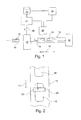
- the Fig. 1 shows a schematic side view of the basic structure of a tube manufacturing apparatus according to a first embodiment of the invention, wherein the representation is limited to an area between a unit 10 for tube production of a tube tube (typically made of a printed film material) in the right portion of the illustration and a cutting unit 12 in the left side Area of presentation.
- An otherwise known tube tube 16 brought continuously out of the unit 10 along a feed direction (arrow direction) 14 is shown schematically with a plurality of identical individual patterns 18 which are provided at regular intervals from one another along the continuous tube 16 and guided to the cutting unit 12. to be isolated there in an otherwise known and not shown in detail in the figure way between the individual patterns 18 in a pipe section 19, which is then completed by further processing operations to a filled or fillable tube.
- a detector unit 20 which is an optical point detector ( Fig. 2 ), which consists in the illustrated embodiment of only a single pixel-like image sensing element 22.
- a continuous detector function of this element 22 then allows, as from the top view of Fig. 2 it can be seen, the scanning of a line-shaped section of a respective, past passing individual pattern 18th
- a control unit 24 typically realized by means of a microcontroller unit, which on the basis of the detected bitwise detector pattern of the detector unit 20, a periodicity of the signals detects, from these a respective current supply position of the tube tube 16 detects and, taking into account suitable feed times or an associated offset, continuously outputs an activation signal A via a connecting line 26 to the cutting unit 12, which then in the known manner the separation of the tube into the majority the single body 19 performs
- control unit 24 implements a correlation unit which, in the described embodiment, references reference data from a memory unit 28 (into which an upstream reference mode was generated by a reference unit 30) in the manner of a correlation to current data of the detector unit 20.
- a correlation unit which, in the described embodiment, references reference data from a memory unit 28 (into which an upstream reference mode was generated by a reference unit 30) in the manner of a correlation to current data of the detector unit 20.
- German patent publication 10 2010 012 858 A1 which in terms of the correlation functionality, such as the local FIGS. 3a, 3b and 4 together with the associated description as belonging to the invention should be included in the present application.
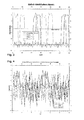
- FIG. 2 shows two comparative diagrams for illustrating the performance of the present invention, wherein a signal (such as that which is conventional by means of print marks) can be clearly identified as a basis for the cutting according to FIG Fig. 3 a complex, noisy signal ( Fig. 4 ), which is only resolvable by the present invention faces.
- a signal such as that which is conventional by means of print marks
- a complex, noisy signal ( Fig. 4 )
- FIG. 4 shows that the phase offset between the four curves shown in FIG. 4, which are offset in time ("expected course" corresponds to the previously stored reference data) in FIG Fig. 3 clearly recognizable and evaluable;
- Such a signal pattern would result from the (in the context of the present invention, however disadvantageous and thus to be avoided) separate print marks.
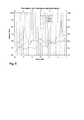
- the Fig. 5 shows in this respect the results of the correlation for the 3 acquired waveforms with the reference signal ("expected course").
- the respective functional maxima for the identification of the individual phases are clearly recognizable.
- FIG. 22 shows a (punctiform) off-center detector position 22, which may typically be selected in response to a respective single pattern 18 and its course.
- an alternative optical detector which is widened, for example, in the transverse direction and detects a plurality of (then to be processed in parallel) single pixels.
- the present invention makes it possible to combine high recognition and cutting accuracy with simplicity and little hardware and processing time, so that the present invention is expected to efficiently produce packaging tubes with short (high-quality) graphics cycles significantly improved.
Landscapes
- Engineering & Computer Science (AREA)
- Mechanical Engineering (AREA)
- Life Sciences & Earth Sciences (AREA)
- Forests & Forestry (AREA)
- Length Measuring Devices By Optical Means (AREA)
Priority Applications (1)
| Application Number | Priority Date | Filing Date | Title |
|---|---|---|---|
| EP13178093.4A EP2829388B1 (fr) | 2013-07-25 | 2013-07-25 | Dispositif de fabrication de tubes ainsi que procédé de fabrication d'un tube |
Applications Claiming Priority (1)
| Application Number | Priority Date | Filing Date | Title |
|---|---|---|---|
| EP13178093.4A EP2829388B1 (fr) | 2013-07-25 | 2013-07-25 | Dispositif de fabrication de tubes ainsi que procédé de fabrication d'un tube |
Publications (2)
| Publication Number | Publication Date |
|---|---|
| EP2829388A1 true EP2829388A1 (fr) | 2015-01-28 |
| EP2829388B1 EP2829388B1 (fr) | 2019-09-04 |
Family
ID=48917351
Family Applications (1)
| Application Number | Title | Priority Date | Filing Date |
|---|---|---|---|
| EP13178093.4A Active EP2829388B1 (fr) | 2013-07-25 | 2013-07-25 | Dispositif de fabrication de tubes ainsi que procédé de fabrication d'un tube |
Country Status (1)
| Country | Link |
|---|---|
| EP (1) | EP2829388B1 (fr) |
Cited By (1)
| Publication number | Priority date | Publication date | Assignee | Title |
|---|---|---|---|---|
| CN111436643A (zh) * | 2019-01-16 | 2020-07-24 | 虹霓机械制造有限公司 | 用于运行烟草加工业的机器的方法和相应的机器 |
Citations (2)
| Publication number | Priority date | Publication date | Assignee | Title |
|---|---|---|---|---|
| US4079664A (en) * | 1976-04-14 | 1978-03-21 | Victor Metal Products Corporation | Collapsible container forming machine |
| DE102010012858A1 (de) | 2010-03-25 | 2011-09-29 | Packsys Global (Switzerland) Ltd. | Vorrichtung und Verfahren zur rotatorischen Ausrichtung eines Tubenkopfes relativ zu einem Tubenkörper |
-
2013
- 2013-07-25 EP EP13178093.4A patent/EP2829388B1/fr active Active
Patent Citations (2)
| Publication number | Priority date | Publication date | Assignee | Title |
|---|---|---|---|---|
| US4079664A (en) * | 1976-04-14 | 1978-03-21 | Victor Metal Products Corporation | Collapsible container forming machine |
| DE102010012858A1 (de) | 2010-03-25 | 2011-09-29 | Packsys Global (Switzerland) Ltd. | Vorrichtung und Verfahren zur rotatorischen Ausrichtung eines Tubenkopfes relativ zu einem Tubenkörper |
Cited By (1)
| Publication number | Priority date | Publication date | Assignee | Title |
|---|---|---|---|---|
| CN111436643A (zh) * | 2019-01-16 | 2020-07-24 | 虹霓机械制造有限公司 | 用于运行烟草加工业的机器的方法和相应的机器 |
Also Published As
| Publication number | Publication date |
|---|---|
| EP2829388B1 (fr) | 2019-09-04 |
Similar Documents
| Publication | Publication Date | Title |
|---|---|---|
| DE102017220361B4 (de) | Verfahren und Testmuster zur Detektion und Kompensation ausgefallener Druckdüsen in einer Inkjet-Druckmaschine | |
| EP3085536A1 (fr) | Procede de detection de buses d'impression defectueuses dans des systemes d'impression a jet d'encre | |
| DE1157016B (de) | Automatisches Erkennen und Bestimmen zweidimensionaler Zeichen | |
| DE102008039025B4 (de) | Verfahren zum berührungslosen Messen der Geschwindigkeit und/oder der Länge eines in Längsrichtung bewegten Strangs, insbesondere eines Kabels | |
| WO2014108329A1 (fr) | Procédé permettant de fabriquer une bande de papier sans fin et dispositif permettant de mettre en œuvre ledit procédé | |
| DE4218760C2 (de) | Anordnung von Registermarken auf einem Druckprodukt und Verfahren zur Ermittlung von Registerabweichungen | |
| DE102008024104A1 (de) | Materialmarkensensor und Verfahren zum Erfassen einer Markierung auf oder in einem Material | |
| DE10254836A1 (de) | Verfahren und Vorrichtung zur Regelung des Registers einer Druckmaschine | |
| DE102011014073A1 (de) | Verfahren zur Regelung eines Druckvorgangs | |
| EP2829388B1 (fr) | Dispositif de fabrication de tubes ainsi que procédé de fabrication d'un tube | |
| EP2559010B1 (fr) | Capteur pour vérification de documents de valeur | |
| DE102019113267B4 (de) | Verfahren zum Betreiben einer Tintenstrahldruckmaschine mit zumindest einer Modifikationsfunktion | |
| EP2917687B1 (fr) | Procédé de détermination de la position d'au moins un bord d'un objet, au moyen de l'évaluation des variations des franges de diffraction de fresnel | |
| EP3124246B1 (fr) | Procede destine a la commande ou au{j} reglage d'un processus de production dans des installations d'impression | |
| DE68912961T2 (de) | Erfassung einer Registermarkierung. | |
| DE102012100956B4 (de) | Tubenherstellungsvorrichtung | |
| EP1154260A2 (fr) | Procédé et appareil de balayage pour la mesure de densité optique | |
| DE102016120752A1 (de) | Verfahren zur Erkennung einer Querbewegung zwischen einer Druckeinheit und einem Aufzeichnungsträger | |
| DE10023127B4 (de) | Verfahren zum Betreiben einer Abtastvorrichtung zur optischen Dichtemessung | |
| EP2112462A1 (fr) | Dispositif de mesure destiné à mesurer l'épaisseur de produits d'impression | |
| DE102020129871B4 (de) | Verfahren zum Einrichten einer Tintenstrahldruckmaschine mit Anpassung von Druckansteuerdaten durch eine Modifikationsfunktion | |
| EP3427957A1 (fr) | Détection de buses d'impression défaillantes au bord d'impression | |
| DE102010055852A1 (de) | Verfahren zum Drucken eines Mehrfarbenbildes auf einer Bedruckstoffbahn | |
| DE202011050286U1 (de) | Druckmaschine mit Registermarkensensor | |
| EP1553034A2 (fr) | Méthode et dispositif de commande des événements synchrone avec une bande en mouvement |
Legal Events
| Date | Code | Title | Description |
|---|---|---|---|
| 17P | Request for examination filed |
Effective date: 20130725 |
|
| AK | Designated contracting states |
Kind code of ref document: A1 Designated state(s): AL AT BE BG CH CY CZ DE DK EE ES FI FR GB GR HR HU IE IS IT LI LT LU LV MC MK MT NL NO PL PT RO RS SE SI SK SM TR |
|
| AX | Request for extension of the european patent |
Extension state: BA ME |
|
| PUAI | Public reference made under article 153(3) epc to a published international application that has entered the european phase |
Free format text: ORIGINAL CODE: 0009012 |
|
| R17P | Request for examination filed (corrected) |
Effective date: 20150727 |
|
| RBV | Designated contracting states (corrected) |
Designated state(s): AL AT BE BG CH CY CZ DE DK EE ES FI FR GB GR HR HU IE IS IT LI LT LU LV MC MK MT NL NO PL PT RO RS SE SI SK SM TR |
|
| STAA | Information on the status of an ep patent application or granted ep patent |
Free format text: STATUS: EXAMINATION IS IN PROGRESS |
|
| 17Q | First examination report despatched |
Effective date: 20180417 |
|
| GRAP | Despatch of communication of intention to grant a patent |
Free format text: ORIGINAL CODE: EPIDOSNIGR1 |
|
| STAA | Information on the status of an ep patent application or granted ep patent |
Free format text: STATUS: GRANT OF PATENT IS INTENDED |
|
| INTG | Intention to grant announced |
Effective date: 20190418 |
|
| GRAS | Grant fee paid |
Free format text: ORIGINAL CODE: EPIDOSNIGR3 |
|
| GRAA | (expected) grant |
Free format text: ORIGINAL CODE: 0009210 |
|
| STAA | Information on the status of an ep patent application or granted ep patent |
Free format text: STATUS: THE PATENT HAS BEEN GRANTED |
|
| AK | Designated contracting states |
Kind code of ref document: B1 Designated state(s): AL AT BE BG CH CY CZ DE DK EE ES FI FR GB GR HR HU IE IS IT LI LT LU LV MC MK MT NL NO PL PT RO RS SE SI SK SM TR |
|
| REG | Reference to a national code |
Ref country code: GB Ref legal event code: FG4D Free format text: NOT ENGLISH |
|
| REG | Reference to a national code |
Ref country code: CH Ref legal event code: EP |
|
| REG | Reference to a national code |
Ref country code: AT Ref legal event code: REF Ref document number: 1174780 Country of ref document: AT Kind code of ref document: T Effective date: 20190915 |
|
| REG | Reference to a national code |
Ref country code: DE Ref legal event code: R096 Ref document number: 502013013496 Country of ref document: DE |
|
| REG | Reference to a national code |
Ref country code: IE Ref legal event code: FG4D Free format text: LANGUAGE OF EP DOCUMENT: GERMAN |
|
| REG | Reference to a national code |
Ref country code: CH Ref legal event code: NV Representative=s name: BODENSEEPATENT PATENTANWAELTE BEHRMANN WAGNER , CH |
|
| REG | Reference to a national code |
Ref country code: NL Ref legal event code: MP Effective date: 20190904 |
|
| REG | Reference to a national code |
Ref country code: LT Ref legal event code: MG4D |
|
| PG25 | Lapsed in a contracting state [announced via postgrant information from national office to epo] |
Ref country code: LT Free format text: LAPSE BECAUSE OF FAILURE TO SUBMIT A TRANSLATION OF THE DESCRIPTION OR TO PAY THE FEE WITHIN THE PRESCRIBED TIME-LIMIT Effective date: 20190904 Ref country code: HR Free format text: LAPSE BECAUSE OF FAILURE TO SUBMIT A TRANSLATION OF THE DESCRIPTION OR TO PAY THE FEE WITHIN THE PRESCRIBED TIME-LIMIT Effective date: 20190904 Ref country code: SE Free format text: LAPSE BECAUSE OF FAILURE TO SUBMIT A TRANSLATION OF THE DESCRIPTION OR TO PAY THE FEE WITHIN THE PRESCRIBED TIME-LIMIT Effective date: 20190904 Ref country code: FI Free format text: LAPSE BECAUSE OF FAILURE TO SUBMIT A TRANSLATION OF THE DESCRIPTION OR TO PAY THE FEE WITHIN THE PRESCRIBED TIME-LIMIT Effective date: 20190904 Ref country code: NO Free format text: LAPSE BECAUSE OF FAILURE TO SUBMIT A TRANSLATION OF THE DESCRIPTION OR TO PAY THE FEE WITHIN THE PRESCRIBED TIME-LIMIT Effective date: 20191204 |
|
| PG25 | Lapsed in a contracting state [announced via postgrant information from national office to epo] |
Ref country code: RS Free format text: LAPSE BECAUSE OF FAILURE TO SUBMIT A TRANSLATION OF THE DESCRIPTION OR TO PAY THE FEE WITHIN THE PRESCRIBED TIME-LIMIT Effective date: 20190904 Ref country code: ES Free format text: LAPSE BECAUSE OF FAILURE TO SUBMIT A TRANSLATION OF THE DESCRIPTION OR TO PAY THE FEE WITHIN THE PRESCRIBED TIME-LIMIT Effective date: 20190904 Ref country code: GR Free format text: LAPSE BECAUSE OF FAILURE TO SUBMIT A TRANSLATION OF THE DESCRIPTION OR TO PAY THE FEE WITHIN THE PRESCRIBED TIME-LIMIT Effective date: 20191205 Ref country code: LV Free format text: LAPSE BECAUSE OF FAILURE TO SUBMIT A TRANSLATION OF THE DESCRIPTION OR TO PAY THE FEE WITHIN THE PRESCRIBED TIME-LIMIT Effective date: 20190904 Ref country code: AL Free format text: LAPSE BECAUSE OF FAILURE TO SUBMIT A TRANSLATION OF THE DESCRIPTION OR TO PAY THE FEE WITHIN THE PRESCRIBED TIME-LIMIT Effective date: 20190904 |
|
| PG25 | Lapsed in a contracting state [announced via postgrant information from national office to epo] |
Ref country code: NL Free format text: LAPSE BECAUSE OF FAILURE TO SUBMIT A TRANSLATION OF THE DESCRIPTION OR TO PAY THE FEE WITHIN THE PRESCRIBED TIME-LIMIT Effective date: 20190904 Ref country code: EE Free format text: LAPSE BECAUSE OF FAILURE TO SUBMIT A TRANSLATION OF THE DESCRIPTION OR TO PAY THE FEE WITHIN THE PRESCRIBED TIME-LIMIT Effective date: 20190904 Ref country code: RO Free format text: LAPSE BECAUSE OF FAILURE TO SUBMIT A TRANSLATION OF THE DESCRIPTION OR TO PAY THE FEE WITHIN THE PRESCRIBED TIME-LIMIT Effective date: 20190904 Ref country code: IT Free format text: LAPSE BECAUSE OF FAILURE TO SUBMIT A TRANSLATION OF THE DESCRIPTION OR TO PAY THE FEE WITHIN THE PRESCRIBED TIME-LIMIT Effective date: 20190904 Ref country code: PT Free format text: LAPSE BECAUSE OF FAILURE TO SUBMIT A TRANSLATION OF THE DESCRIPTION OR TO PAY THE FEE WITHIN THE PRESCRIBED TIME-LIMIT Effective date: 20200106 Ref country code: PL Free format text: LAPSE BECAUSE OF FAILURE TO SUBMIT A TRANSLATION OF THE DESCRIPTION OR TO PAY THE FEE WITHIN THE PRESCRIBED TIME-LIMIT Effective date: 20190904 |
|
| PG25 | Lapsed in a contracting state [announced via postgrant information from national office to epo] |
Ref country code: SM Free format text: LAPSE BECAUSE OF FAILURE TO SUBMIT A TRANSLATION OF THE DESCRIPTION OR TO PAY THE FEE WITHIN THE PRESCRIBED TIME-LIMIT Effective date: 20190904 Ref country code: IS Free format text: LAPSE BECAUSE OF FAILURE TO SUBMIT A TRANSLATION OF THE DESCRIPTION OR TO PAY THE FEE WITHIN THE PRESCRIBED TIME-LIMIT Effective date: 20200224 Ref country code: SK Free format text: LAPSE BECAUSE OF FAILURE TO SUBMIT A TRANSLATION OF THE DESCRIPTION OR TO PAY THE FEE WITHIN THE PRESCRIBED TIME-LIMIT Effective date: 20190904 Ref country code: CZ Free format text: LAPSE BECAUSE OF FAILURE TO SUBMIT A TRANSLATION OF THE DESCRIPTION OR TO PAY THE FEE WITHIN THE PRESCRIBED TIME-LIMIT Effective date: 20190904 |
|
| REG | Reference to a national code |
Ref country code: DE Ref legal event code: R097 Ref document number: 502013013496 Country of ref document: DE |
|
| PLBE | No opposition filed within time limit |
Free format text: ORIGINAL CODE: 0009261 |
|
| STAA | Information on the status of an ep patent application or granted ep patent |
Free format text: STATUS: NO OPPOSITION FILED WITHIN TIME LIMIT |
|
| PG2D | Information on lapse in contracting state deleted |
Ref country code: IS |
|
| PG25 | Lapsed in a contracting state [announced via postgrant information from national office to epo] |
Ref country code: DK Free format text: LAPSE BECAUSE OF FAILURE TO SUBMIT A TRANSLATION OF THE DESCRIPTION OR TO PAY THE FEE WITHIN THE PRESCRIBED TIME-LIMIT Effective date: 20190904 Ref country code: IS Free format text: LAPSE BECAUSE OF FAILURE TO SUBMIT A TRANSLATION OF THE DESCRIPTION OR TO PAY THE FEE WITHIN THE PRESCRIBED TIME-LIMIT Effective date: 20200105 |
|
| 26N | No opposition filed |
Effective date: 20200605 |
|
| PG25 | Lapsed in a contracting state [announced via postgrant information from national office to epo] |
Ref country code: SI Free format text: LAPSE BECAUSE OF FAILURE TO SUBMIT A TRANSLATION OF THE DESCRIPTION OR TO PAY THE FEE WITHIN THE PRESCRIBED TIME-LIMIT Effective date: 20190904 |
|
| PG25 | Lapsed in a contracting state [announced via postgrant information from national office to epo] |
Ref country code: MC Free format text: LAPSE BECAUSE OF FAILURE TO SUBMIT A TRANSLATION OF THE DESCRIPTION OR TO PAY THE FEE WITHIN THE PRESCRIBED TIME-LIMIT Effective date: 20190904 |
|
| REG | Reference to a national code |
Ref country code: CH Ref legal event code: PFA Owner name: PACKSYS GLOBAL (SWITZERLAND) LTD., CH Free format text: FORMER OWNER: PACKSYS GLOBAL (SWITZERLAND) LTD., CH |
|
| GBPC | Gb: european patent ceased through non-payment of renewal fee |
Effective date: 20200725 |
|
| REG | Reference to a national code |
Ref country code: BE Ref legal event code: MM Effective date: 20200731 |
|
| PG25 | Lapsed in a contracting state [announced via postgrant information from national office to epo] |
Ref country code: GB Free format text: LAPSE BECAUSE OF NON-PAYMENT OF DUE FEES Effective date: 20200725 Ref country code: LU Free format text: LAPSE BECAUSE OF NON-PAYMENT OF DUE FEES Effective date: 20200725 |
|
| PG25 | Lapsed in a contracting state [announced via postgrant information from national office to epo] |
Ref country code: BE Free format text: LAPSE BECAUSE OF NON-PAYMENT OF DUE FEES Effective date: 20200731 |
|
| PG25 | Lapsed in a contracting state [announced via postgrant information from national office to epo] |
Ref country code: IE Free format text: LAPSE BECAUSE OF NON-PAYMENT OF DUE FEES Effective date: 20200725 |
|
| REG | Reference to a national code |
Ref country code: AT Ref legal event code: MM01 Ref document number: 1174780 Country of ref document: AT Kind code of ref document: T Effective date: 20200725 |
|
| PG25 | Lapsed in a contracting state [announced via postgrant information from national office to epo] |
Ref country code: AT Free format text: LAPSE BECAUSE OF NON-PAYMENT OF DUE FEES Effective date: 20200725 |
|
| PG25 | Lapsed in a contracting state [announced via postgrant information from national office to epo] |
Ref country code: TR Free format text: LAPSE BECAUSE OF FAILURE TO SUBMIT A TRANSLATION OF THE DESCRIPTION OR TO PAY THE FEE WITHIN THE PRESCRIBED TIME-LIMIT Effective date: 20190904 Ref country code: MT Free format text: LAPSE BECAUSE OF FAILURE TO SUBMIT A TRANSLATION OF THE DESCRIPTION OR TO PAY THE FEE WITHIN THE PRESCRIBED TIME-LIMIT Effective date: 20190904 Ref country code: CY Free format text: LAPSE BECAUSE OF FAILURE TO SUBMIT A TRANSLATION OF THE DESCRIPTION OR TO PAY THE FEE WITHIN THE PRESCRIBED TIME-LIMIT Effective date: 20190904 |
|
| PG25 | Lapsed in a contracting state [announced via postgrant information from national office to epo] |
Ref country code: MK Free format text: LAPSE BECAUSE OF FAILURE TO SUBMIT A TRANSLATION OF THE DESCRIPTION OR TO PAY THE FEE WITHIN THE PRESCRIBED TIME-LIMIT Effective date: 20190904 |
|
| PGFP | Annual fee paid to national office [announced via postgrant information from national office to epo] |
Ref country code: DE Payment date: 20250730 Year of fee payment: 13 |
|
| PGFP | Annual fee paid to national office [announced via postgrant information from national office to epo] |
Ref country code: BG Payment date: 20250718 Year of fee payment: 13 |
|
| PGFP | Annual fee paid to national office [announced via postgrant information from national office to epo] |
Ref country code: FR Payment date: 20250723 Year of fee payment: 13 |
|
| PGFP | Annual fee paid to national office [announced via postgrant information from national office to epo] |
Ref country code: CH Payment date: 20250801 Year of fee payment: 13 |