EP2829312A1 - Vorrichtung zur Absaugung von in Abgasen enthaltenem saurem Gas - Google Patents
Vorrichtung zur Absaugung von in Abgasen enthaltenem saurem Gas Download PDFInfo
- Publication number
- EP2829312A1 EP2829312A1 EP14178183.1A EP14178183A EP2829312A1 EP 2829312 A1 EP2829312 A1 EP 2829312A1 EP 14178183 A EP14178183 A EP 14178183A EP 2829312 A1 EP2829312 A1 EP 2829312A1
- Authority
- EP
- European Patent Office
- Prior art keywords
- fluid
- regeneration
- acid gas
- vapor
- turbine
- Prior art date
- Legal status (The legal status is an assumption and is not a legal conclusion. Google has not performed a legal analysis and makes no representation as to the accuracy of the status listed.)
- Granted
Links
Images


Classifications
-
- F—MECHANICAL ENGINEERING; LIGHTING; HEATING; WEAPONS; BLASTING
- F01—MACHINES OR ENGINES IN GENERAL; ENGINE PLANTS IN GENERAL; STEAM ENGINES
- F01K—STEAM ENGINE PLANTS; STEAM ACCUMULATORS; ENGINE PLANTS NOT OTHERWISE PROVIDED FOR; ENGINES USING SPECIAL WORKING FLUIDS OR CYCLES
- F01K17/00—Using steam or condensate extracted or exhausted from steam engine plant
- F01K17/04—Using steam or condensate extracted or exhausted from steam engine plant for specific purposes other than heating
-
- B—PERFORMING OPERATIONS; TRANSPORTING
- B01—PHYSICAL OR CHEMICAL PROCESSES OR APPARATUS IN GENERAL
- B01D—SEPARATION
- B01D53/00—Separation of gases or vapours; Recovering vapours of volatile solvents from gases; Chemical or biological purification of waste gases, e.g. engine exhaust gases, smoke, fumes, flue gases, aerosols
- B01D53/14—Separation of gases or vapours; Recovering vapours of volatile solvents from gases; Chemical or biological purification of waste gases, e.g. engine exhaust gases, smoke, fumes, flue gases, aerosols by absorption
- B01D53/1425—Regeneration of liquid absorbents
-
- B—PERFORMING OPERATIONS; TRANSPORTING
- B01—PHYSICAL OR CHEMICAL PROCESSES OR APPARATUS IN GENERAL
- B01D—SEPARATION
- B01D53/00—Separation of gases or vapours; Recovering vapours of volatile solvents from gases; Chemical or biological purification of waste gases, e.g. engine exhaust gases, smoke, fumes, flue gases, aerosols
- B01D53/14—Separation of gases or vapours; Recovering vapours of volatile solvents from gases; Chemical or biological purification of waste gases, e.g. engine exhaust gases, smoke, fumes, flue gases, aerosols by absorption
- B01D53/1456—Removing acid components
-
- B—PERFORMING OPERATIONS; TRANSPORTING
- B01—PHYSICAL OR CHEMICAL PROCESSES OR APPARATUS IN GENERAL
- B01D—SEPARATION
- B01D2258/00—Sources of waste gases
- B01D2258/02—Other waste gases
- B01D2258/0283—Flue gases
-
- B—PERFORMING OPERATIONS; TRANSPORTING
- B01—PHYSICAL OR CHEMICAL PROCESSES OR APPARATUS IN GENERAL
- B01D—SEPARATION
- B01D2259/00—Type of treatment
- B01D2259/65—Employing advanced heat integration, e.g. Pinch technology
-
- B—PERFORMING OPERATIONS; TRANSPORTING
- B01—PHYSICAL OR CHEMICAL PROCESSES OR APPARATUS IN GENERAL
- B01D—SEPARATION
- B01D53/00—Separation of gases or vapours; Recovering vapours of volatile solvents from gases; Chemical or biological purification of waste gases, e.g. engine exhaust gases, smoke, fumes, flue gases, aerosols
- B01D53/14—Separation of gases or vapours; Recovering vapours of volatile solvents from gases; Chemical or biological purification of waste gases, e.g. engine exhaust gases, smoke, fumes, flue gases, aerosols by absorption
- B01D53/1456—Removing acid components
- B01D53/1475—Removing carbon dioxide
-
- Y—GENERAL TAGGING OF NEW TECHNOLOGICAL DEVELOPMENTS; GENERAL TAGGING OF CROSS-SECTIONAL TECHNOLOGIES SPANNING OVER SEVERAL SECTIONS OF THE IPC; TECHNICAL SUBJECTS COVERED BY FORMER USPC CROSS-REFERENCE ART COLLECTIONS [XRACs] AND DIGESTS
- Y02—TECHNOLOGIES OR APPLICATIONS FOR MITIGATION OR ADAPTATION AGAINST CLIMATE CHANGE
- Y02E—REDUCTION OF GREENHOUSE GAS [GHG] EMISSIONS, RELATED TO ENERGY GENERATION, TRANSMISSION OR DISTRIBUTION
- Y02E20/00—Combustion technologies with mitigation potential
- Y02E20/32—Direct CO2 mitigation
Definitions
- the field of the invention is that of the capture of acid gas contained in combustion fumes of a thermal power plant comprising a steam circuit, in particular a flame thermal power station.
- Techniques for capturing acid gas, in particular carbon dioxide, which have reached the greatest maturity are based on the chemical absorption of the acid gas in a capture fluid comprising a solvent, in particular an amine-based solvent.
- a capture fluid comprising a solvent, in particular an amine-based solvent.
- a regeneration step requires a large amount of heat. This heat usually comes from a strong condensation of low pressure vapor of the steam circuit. It is necessary to condense a large part of the low pressure steam, typically between 30 and 60%.
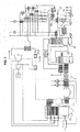
- FIG. 1 there is described a synthetic diagram of a power plant comprising an acid gas collection device according to such a known technique.
- the fumes resulting from the combustion of a boiler 18 are conveyed via a pipe system 21 to means 10 for absorbing at least one acid gas.
- the absorption of gas acid is produced by contacting the fumes with a capture fluid comprising a solvent, the capture fluid being poor in acid gas.
- the capture fluid from the absorption means 10 is thus the capture fluid enriched with acid gas.
- the device comprises a regenerator 1, in which the capture fluid enriched in acid gas is brought into contact with the vapor of a regeneration fluid. This vapor of the regeneration fluid is introduced to regenerate the capture fluid in the regenerator 1 by introduction means 11.
- the device comprises condensation means 101 arranged at the top of the regenerator 1.
- the condensation means are adapted to condense the gaseous fluid from the regenerator into a medium containing a liquid phase of the regeneration fluid and a gas phase rich in acid gas.
- the liquid phase of the regeneration fluid is reintroduced into the regenerator by return means 22 of the regeneration fluid.
- the acid gas is isolated in the gaseous phase rich in acid gas.
- the heat required for the regenerator 1 is supplied to the regeneration fluid by a low-pressure steam taken from the steam circuit of the plant, via a fluid connection represented by the two arrows referenced A, and with which the regeneration fluid is in heat exchange in the reboiler 102.
- the vapor removed has partially condensed in the reboiler 102, thus forming a fluid which is reinjected via a fluid connection represented by the two arrows referenced B in the steam circuit of the plant.
- auxiliaries comprise, for example, a system for pumping the capture fluid, a fan, or a acid gas compressor.
- auxiliary losses typically amount to about 3% of the steam cycle efficiency.
- One possibility is to reduce the pressure of the steam required by the reboiler.
- the use of lower pressure steam reduces the impact of steam sampling on plant performance.
- such a possibility requires a significant increase in the size of the equipment of the device, because of a lower operating pressure, and involves a greater compression work to supply the acid gas to an acid gas transport network.
- Another possibility is to modify the steam cycle in order to optimize the amount of steam required for the cycle.
- Such a possibility generally implies an increase in the complexity of the boiler and the steam circuit.
- An object of the invention is to provide a device for collecting acid gas contained in combustion fumes of a thermal power plant comprising a steam circuit that does not have these disadvantages.
- an object of the invention is to provide such a device which reduces the loss of efficiency associated with the regeneration of CO2.
- the invention relates to a thermal plant comprising a steam circuit and a boiler, the plant comprising such a device.
- a device for collecting an acid gas contained in combustion fumes of a thermal power plant comprising a steam circuit.
- the acid gas is for example carbon dioxide.
- the capture device is a device adapted to capture an acid gas contained in combustion fumes, such as combustion fumes from a thermal power station.
- the sensing device is for example dimensioned or configured to capture such an acid gas.
- the arrow elements A, B and C represent fluidic connections of a given element to another.
- the plant is for example a thermal power station.
- the steam circuit or steam circuit of the thermal power station comprises at least one low pressure turbine.
- low pressure is meant for example a pressure of between 2 and 5 bar.
- the steam circuit may include a plurality of low pressure turbines.
- the steam circuit may comprise one or more high pressure turbine (s).
- the steam circuit may comprise one or more turbine (s) intermediate pressure. Turbines are for example arranged along a drive shaft.
- the steam circuit may comprise exchangers in which the steam passes between each turbine, the exchangers making it possible to supply heat to the working fluid coming from the low-pressure turbines before it evaporates in a boiler 18.
- the steam circuit can thus form a fluidic circuit of the steam in the thermal power plant ensuring the operation of the turbines of the thermal power plant and thus the power generation of the thermal power station.
- the boiler 18 produces fumes that result from the combustion of a fuel.
- a fuel can be any fuel of a thermal power station, in particular a thermal flame station, whose fumes contain at least one acid gas that the capture device aims to capture.
- the fuel is for example coal or a hydrocarbon.
- the sensing device comprises absorption means 10 of the acid gas.
- the flue gases from the boiler 18 are conveyed to the absorption means 10.
- Upstream of the absorption means 10 may be arranged cooling means, for example a cooler, and / or smoke aeration means, and / or means for cleaning up the fumes.
- the fumes are brought into contact with a capture fluid comprising a solvent, the capture fluid being poor in acid gas adapted to absorb the acid gas.
- the absorption means 10 comprise, for example, an absorber.
- the absorber comprises for example a multi-section column.
- the absorption means 10 of an acid gas are suitable means for carrying out the absorption of an acid gas.
- the absorption means 10 are adapted to ensure the contact of the fumes with a fluid low in acid gas, to allow the acid gas to be absorbed by the acidic gas-poor capture fluid.
- the absorption means 10 are for example sized or configured to allow such absorption of the acid gas.
- the absorption means 10 comprise, for example, an absorber.
- the capture fluid comprises or is for example an aqueous solvent.
- the capture fluid advantageously has a low regeneration energy.
- the capture fluid comprises, for example, potassium salts of carbonate.
- the capture fluid comprises or is for example an aqueous solution of amine, forming a solvent, for example an aqueous solution of methyl diethanolamine.
- the capture fluid advantageously has low volatility.
- the uptake fluid may comprise piperazine, or amino acid salts.
- the device is adapted to operate with such a capture fluid.
- the fumes from which the acid gas has been absorbed can be discharged, for example at the top of the absorber. Evacuated fumes may undergo other treatments.
- the sensing device comprises a regenerator 1 in which the capture fluid enriched in acid gas is brought into contact with the vapor of a regeneration fluid introduced in order to regenerate the collection fluid.
- the device thus comprises first means 11 for introducing the vapor of the regeneration fluid into the regenerator 1, arranged in such a way that the vapor of the regeneration fluid introduced in order to regenerate the capture fluid is superheated steam.
- Superheated steam is injected into the regenerator to minimize heat transfer and maximize material transfer.
- the superheated steam preferably has a pressure between 0.3 and 10 bar.
- the superheated steam has preferably undergone an overheating of +20 to + 70 ° C.
- the regeneration fluid may be water.
- Regenerator means an apparatus in which a chemical compound is regenerated, so as to restore its activity.
- the regenerator is adapted to bring into contact the capture fluid enriched in acid gas and the vapor of a regeneration fluid, so that such a contact is made inside the regenerator.
- the regenerator is adapted so that the vapor of a regeneration fluid is introduced inside the regenerator, so as to regenerate the capture fluid by such contacting.
- the regenerator is for example configured or sized to allow in the regenerator such contacting.
- the device thus comprises first introduction means 11 adapted to introduce vapor of the regeneration fluid into the regenerator 1, arranged so that the vapor of the fluid of regeneration introduced to regenerate the capture fluid is superheated steam.
- the first input means are for example configured or dimensioned to allow such an introduction and such an arrangement.
- the first input means 11 comprise for example an introducer element, for example an introduction conduit.
- the device is adapted to operate with such a regeneration fluid.
- the regenerator 1 comprises contact means between the capture fluid enriched in acid gas and the superheated steam of the regeneration fluid.
- the contact means are adapted to limit the contact time between the capture fluid enriched in acid gas and the superheated steam of the regeneration fluid so that substantially maintains the vapor flow of the regeneration fluid.
- the contact time between the capture fluid enriched in acid gas and the vapor of the regeneration fluid must not be too great not to condense too much regeneration fluid vapor in the capture fluid.
- the contact means comprise, for example, a packed column, a bubble column or a spray column whose height / diameter ratio is optimized for this purpose.
- the contact means between the acid gas enriched capture fluid and the superheated steam of the regeneration fluid are suitable means for bringing the acid-enriched capture fluid and the superheated steam of the regeneration fluid into contact.
- the contact means between the capture fluid enriched in acid gas and the superheated steam of the regeneration fluid are for example configured or dimensioned to allow such contacting.
- the limitation of the contact time described is thus obtained for example by the arrangement and / or the sizing of the sensing device, in particular the constituent elements of the sensing device, in particular the regenerator and / or fluidically connected elements. to the regenerator.
- the limitation of the contact time is for example obtained in particular by the dimensioning of the packing column and / or by the choice of values of state variables of the fluids circulating in the device.
- the regenerator 1 may comprise a column with multiple packings and / or trays.
- the fluid at the bottom of the regenerator comprising a large proportion of acid-poor capture fluid, can be reintroduced into the absorption means 10, by means comprising, for example, a pump 101 and / or a ramp spray system (not shown).
- the capture fluid that is poor in acid gas can thus be reintroduced into the absorption means 10.
- the fluid coming from the bottom of the regenerator can be cooled by dedicated cooling means, for example a cooler 103 in which the fluid from the bottom of the regenerator 1 is in heat exchange with a cold source, for example a cold source of an external water circuit.
- the fluid at the bottom of the absorption means 10 can be introduced into the regenerator 1, for example from a scrubber of the absorption means or a washing stage, by means comprising a pump 104.
- an exchanger 105 may be arranged in such a way that the fluid coming from the bottom of the regenerator 1 transfers part of its heat to the fluid coming from the bottom of the absorption means 10.
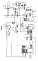
- the device comprises a first evapo-condenser.
- the first evapo-condenser comprises first condensation means in a medium containing a liquid phase of the regeneration fluid and a gaseous phase rich in acid gas, disposed at the top of said regenerator 1.
- first condensation means in a medium containing a liquid phase of the regeneration fluid and a gaseous phase rich in acid gas, disposed at the top of said regenerator 1.
- the first condensation means are adapted to allow condensation in a medium containing a liquid phase of the regeneration fluid and a gaseous phase rich in acid gas.
- the first condensing means are for example configured or dimensioned to allow such condensation.
- the first condensing means comprise, for example, a condenser.
- the first condensation means may comprise partial condensers 2, 3 and 4 adapted to limit the proportion of impurities in the liquid phase of regeneration fluid condensed by the first condensing means. At least one liquid portion of regeneration fluid can thus be partially condensed by a partial condenser, for example at the level of the partial condenser drum 3, in order to be recycled in the regenerator 1, for example by return means 22. Recycling is for example facilitated by a pump 301.
- the first condensation means may thus comprise a succession of heat exchangers 2, 4 separated by the partial condenser balloon 3.
- Each partial condenser makes it possible, for example, to condense part of the portion of the regeneration fluid condensed by the first condensation means as a whole.
- the device comprises separation means 6 of the liquid phase of the regeneration fluid and the gas phase rich in acid gas.
- the separation means 6 are thus arranged downstream of the first condensing means.
- Upstream of the separation means 6 may be arranged dedicated cooling means, for example a cooler 5 by a cold source of an external water circuit.
- the device may further comprise purification means 7 of the separated aqueous liquid phase.
- purification means 7 may be located downstream of the separation means 6.
- the purification means 7 may comprise a pump 701 disposed upstream of a purification system 702 as such.
- An expander 703 may be disposed downstream of the purification system 702.
- the purification system 702 may comprise a packed column.
- the purification system 702 may comprise an activated carbon filtration system and / or an ion exchange resin system, and / or an electrodialysis system, and / or any other suitable system.
- the absorption means 10 may be adapted to evaporate an excess of regeneration fluid present in the capture fluid, and mix said surplus of evaporated regeneration fluid with the liquid phase of the regeneration fluid downstream of the first condensing means.
- the liquid phase of the regeneration fluid has, for example, been separated by the separation means 6 before being mixed with the excess regeneration fluid.
- the mixture of the fluid of the excess of the regeneration fluid and the liquid phase of the regeneration fluid can be produced at the separation means 6.
- the mixture can be allowed by means of transfer of the excess fluid 23 additionally represented in figure 2a by the two arrows referenced C, one from the absorption means 10, the other directed towards the separation means 6.
- the regeneration fluid downstream of the first condensing means may be in a liquid state.
- the absorption means 10 may for example be adapted to allow the evaporation of an excess of regeneration fluid present in the capture fluid when the device is in operation, and to allow the mixing of said surplus fluid regeneration evaporated with the liquid phase of the regeneration fluid downstream of the first condensing means when the device is in operation.
- the evaporation is for example permitted by a chamber dimensioned for this purpose in its shape and size, combined with an element for heating the inside of the enclosure, and the mixture is for example obtained by a structure allowing the introduction by introduction conduits of the fluids to be mixed and their maintenance in the chamber under predefined conditions ensured by the control of the internal conditions of the enclosure, for example by the heating means.
- the first evaporator-condenser comprises first evaporation means of the first evaporator-condenser, which are in heat exchange with the first condensing means.
- the first evaporation means evaporate a working fluid.
- the working fluid is adapted to be turbined after passing through the first evaporation means.
- the working fluid may be a working fluid of a turbine, in particular a low pressure turbine.
- the working fluid may be water. In the case where the working fluid is water, it is preferably introduced into the first evaporation means at a pressure for example between 0.3 and 6 bar, for example about 1 bar.
- the device is adapted to operate with such a working fluid.
- the device comprises first means of reintroduction 13 of the steam of the working fluid, thus obtained by the evaporation means, in a first turbine 14.
- the first turbine 14 may be a low pressure turbine of the steam circuit of the thermal power station.
- the steam cycle efficiency associated with the steam circuit is improved because less heat is needed.
- the heat supplied serves to desorb the acid gas, not to heat the capture fluid or to boil the working fluid or the regeneration fluid.
- the device may furthermore comprise means for sudden expansion (not shown) of the working fluid upstream of the first evaporation means, a vapor phase of the relaxed working fluid being introduced into the turbine by the first reintroduction means, and a liquid phase of the relaxed working fluid being reintroduced into a preheat train.
- Such a sudden expansion can notably make it possible to increase the vapor content of the working fluid at the outlet of the first evaporator-condenser.
- the sudden expansion means are for example adapted to perform a sudden expansion of the working fluid upstream of the first evaporation means, the sudden expansion means being for example arranged to allow the introduction of a vapor phase of the working fluid. expanded in the turbine by the first reintroduction means, and arranged to allow the reintroduction of a liquid phase of the working fluid expanded in a preheat train.
- the sudden expansion means comprise for example a quick expansion valve.
- the capture device may comprise means 8 for compressing the gas phase rich in acid gas, in heat exchange with the first evapo-condenser.
- the compression means 8 may comprise a compression train comprising first compression means 801 at a first pressure, and second compression means 802 at a second pressure greater than the first pressure.
- the first compression means 801 and the second compression means 802 may for example be separated by acid gas drying means.
- the means for drying the acid gas make it possible, for example, to separate the water contained in the acid gas and the dried acid gas, the latter being introduced into the second compression means 802.
- the water contained can then be transmitted to a water treatment system (not shown).
- the drying means may comprise a container 803 in which the fluid from the first compression means 801 is introduced.
- the drying means may furthermore comprise dedicated cooling means, for example a cooler 804 in which the fluid from the first means compression 801, or alternatively the container 803 (alternative not shown), is in heat exchange with a cold source, for example a cold source of an external water circuit.
- An exchanger 9 can be arranged between the first compression means 801 and the second compression means 802, so that the heat issuing from the compression means 8 makes it possible to evaporate at least partially the working fluid, for example the working fluid.
- the heat resulting from the compression means 8 can be used to evaporate at least partially the regeneration fluid upstream of the regenerator 1 by means of an exchanger (not shown).
- the acid gas which can be in a supercritical state, can be cooled by a cooler 805 where the acid gas is in heat exchange with a cold source, for example a cold source of an external water circuit.
- the acid gas at the outlet of the compression train can be directed towards an acid gas transport network, for example by means of a pump 806.
- the compression means 8 of the gas phase rich in acid gas are for example arranged to be in heat exchange with the first evaporator-condenser. Such an exchange may be adapted to allow, when the device is in operation to evaporate at least partially the working fluid, and / or at least partially evaporating the regeneration fluid upstream of the regenerator.
- Two elements are in heat exchange when they are adapted to allow a heat exchange between fluids arranged in each of the elements without requiring the mixing of fluids.
- the compression means comprise for example a compressor.
- the first condensation means having made it possible to cool the gas phase rich in acid gas, and the gas phase having fewer traces of regeneration fluid, it is not necessary to couple the compression means 8 to multiple partial condensers associated with condenser balloons for collecting the cooling fluid for reintroduction in the regenerator 1.
- the gas phase has already undergone these partial condensation and cooling operations, which facilitates its treatment. It is thus possible to recover first condensates rich in capture fluid, in particular rich in solvent, and condensates rich in regeneration fluid.
- the heat dissipated by the compression of the acid gas can be used to further increase the vapor content of the working fluid stream reintroduced by the first reintroduction means 13.
- the first evapo-condenser may be a column directly contacting the fluid of the first condensing means and the fluid of the first evaporation means.
- the first evapo-condenser may be for example a column adapted to directly contact the fluid of the first condensing means and the fluid of the first evaporation means.
- the first evapo-condenser may be for example a column configured or dimensioned to directly contact the fluid of the first condensing means and the fluid of the first evaporation means.
- the first means 11 for introducing the regeneration fluid vapor into the regenerator 1 may be first means for introducing the vapor from a second turbine 110, for example via a fluidic connection represented by the two arrows referenced A, the second turbine 110 being able to be a turbine of said steam circuit of the thermal power station.
- the regeneration fluid and the working fluid may be formed of the same operating fluid of the steam circuit, the turbine 14 then belonging to the steam circuit.
- the nip of the reboiler namely the temperature difference between the condensation temperature of the sampled steam and the temperature of the regeneration fluid at the inlet of the reboiler, implies a strictly negative yield within the meaning of the second principle of thermodynamics.
- the fluid can be directly reintroduced into a low pressure turbine of the steam circuit, without the need for additional evaporation or overheating.
- the device can be coupled to a net supercritical coal plant of 1.05 GW net, whose vapor conditions are 270 bar / 600 ° C / 60 bar / 600 ° C, and of 45.2% lower PCI (Gross Heating Value) yield with a carbon dioxide capture process with monoethanolamine (35% by mass).
- the working fluid is water.
- the operating pressure of the regenerator 1 is 2.7 bars.
- the capture rate of carbon dioxide is 90% or 700 t / h of carbon dioxide.
- the superheated steam of the working fluid to be injected by the first introduction means 11 is taken up by a low pressure turbine 14 at 2.7 bars and 194 ° C.
- the regenerator 1 has a column having a layer of structured packing, for example 250 m 2 / m 3 , 3 meters. Leaving the top of the regenerator 1, the fluid comprising the working fluid and the carbon dioxide is condensed at 130 ° C., then at 95 ° C. by the first condensation means of the first evaporator-condenser, and then at 40 ° C. a cooler.
- the carbon dioxide separated by the separation means 6 is compressed by the compression means 8 to 70 bar before being dehydrated and then compressed to 110 bar.
- the liquid phase of the working fluid separated by the separation means 6 is treated by purification means 7 so as to separate the working fluid impurities such as traces of capture fluid, solvents or carbonates.
- the purified working fluid is expanded by a pressure regulator 703 at 1.5 bar and then introduced into the first evaporation means to acquire a vapor titre of 0.935, for example if the first evapo-condenser comprises several partial condensers 2 and 4 and is heat exchange with the compression means 8.
- the steam is then reintroduced by the first reintroduction means 13 in the steam circuit of the plant, for example via a fluid connection represented by the two arrows referenced B, where it is mixed with superheated steam at 1.5 bar. This results in a slightly superheated steam at 1.5 bar which will feed another part of the low pressure turbine.
- Energy consumption for fans, recirculation pumps of the capture fluid, compression means 8 represent about 65 MW to which must be added 2 MW for a pump extraction of the first condensing means, and 5 MW for means of purification 7 comprising an electrodialysis system.
- the loss of electrical output on the turbine train is 90 MW.
- the need for increased cooling water requires an additional 5 MW of pumping power.
- the total loss of electrical power is therefore 102 MW, giving a net output of 0.95 GW and a net return of 38.2%.
- the yield loss due to the installation of the carbon capture unit is 7%.
- the first means 11 for introducing the regeneration fluid vapor into the regenerator 1 may be first means for introducing the vapor from a second turbine 110, the second turbine 110 possibly being a turbine of said steam circuit of the thermal power station.
- the regeneration fluid and the working fluid may be formed of the same operating fluid of the steam circuit, the turbine 14 then belonging to the steam circuit.
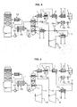
- the device may comprise overheating means 15 adapted to reheat the working fluid downstream of the first evapo-condenser, in particular downstream of the first evaporation means and before reintroduction into the steam circuit by the first means of cooling. reintroduction 13.
- the superheating means 15 can provide heat from the boiler 18 (not shown figure 3 ). This allows further improvement of the steam cycle. This also makes it possible to operate the regenerator 1 at a higher pressure and / or to better value the heat generated in the boiler 18.
- the superheating means 15 are for example arranged downstream of the first evapo-condenser, so as to allow the reheating of the working fluid from the first evapo-condenser.
- the superheating means 15 comprise for example a reheater.
- the first means 11 for introducing the regeneration fluid vapor into the regenerator 1 may be first means for introducing steam from a turbine, which can then be the first turbine 14 (shown in FIG. figure 4 ) or the second turbine 110 (not shown figure 4 ), this turbine can then be a turbine of said steam circuit of the thermal power plant.
- the regeneration fluid and the working fluid may be formed of the same operating fluid of the steam circuit.
- the turbine 14 then belonging to the steam circuit.
- the first introduction means 11 may comprise a dedicated boiler 111 or several dedicated boilers.
- the first introduction means 11 may comprise a pump 112 arranged between the boilers 111.
- the steam circuit may be a steam circuit dedicated to the device comprising a first turbine 14 dedicated more robust. It is thus possible to avoid the problems caused by the presence of trace capture fluid, in particular solvent, or carbonate ions in the other turbines of the plant.
- the first means 11 for introducing the regeneration fluid vapor into the regenerator 1 may be first means for introducing the vapor from a second turbine 110, the second turbine 110 then being a turbine of said steam circuit of the thermal power station.
- the first turbine 14 may belong to a closed working fluid circuit 16 separate from the steam circuit, the working fluid circuit 16 thus forming an organic Rankine cycle.
- the first evapo-condenser can thus act as a hot source of the organic Rankine cycle.
- the device may comprise second reintroduction means 17 for the separate regeneration fluid at a boiler 18 (not shown figure 5 ) of the steam circuit.
- the device may comprise a second evaporator-condenser 19.
- the second evaporator-condenser 19 may comprise second means for condensing the working fluid, located upstream of the first evaporator-condenser, the second condensing means being adapted to condense said fluid. working.
- the device may furthermore comprise second means 20 for introducing the working fluid from the steam circuit of the thermal power station into the second condensation means 19.
- the second evapo-condenser 19 may comprise second evaporation means which evaporate the regeneration fluid downstream of the separation means 6 and upstream of the first introduction means 11, the second evaporation means then being in heat exchange with the second condensation means.
- the first evapo-condenser acts in particular as a condenser of the regenerator 1 while the second evaporator-condenser acts in particular as a boiler of the regenerator 1. It is thus possible to avoid a direct contact of the vapor and the capture fluid .
- the second evapo-condenser can directly contact the fluid of the second condensation means and the fluid of the second evaporation means.
- the second evapo-condenser may for example thus comprise second evaporation means which are adapted to evaporate the regeneration fluid downstream of the separation means 6 and upstream of the first introduction means 11, the second evaporation means being adapted to be in heat exchange with the second condensing means.
- the second evaporation means may for example be configured or dimensioned to evaporate such fluid and / or configured or sized to be in such a heat exchange.
- the second evapo-condenser may for example be adapted to directly contact the fluid of the second condensation means and the fluid of the second evaporation means.
- the second evaporator-condenser may for example be configured or sized to directly contact the fluid of the second condensing means and the fluid of the second evaporation means.
Landscapes
- Chemical & Material Sciences (AREA)
- Engineering & Computer Science (AREA)
- Analytical Chemistry (AREA)
- General Chemical & Material Sciences (AREA)
- Oil, Petroleum & Natural Gas (AREA)
- Chemical Kinetics & Catalysis (AREA)
- Combustion & Propulsion (AREA)
- Mechanical Engineering (AREA)
- General Engineering & Computer Science (AREA)
- Gas Separation By Absorption (AREA)
Applications Claiming Priority (1)
| Application Number | Priority Date | Filing Date | Title |
|---|---|---|---|
| FR1357262A FR3008898B1 (fr) | 2013-07-23 | 2013-07-23 | Dispositif de captage de gaz acide contenu dans des fumees de combustion |
Publications (2)
| Publication Number | Publication Date |
|---|---|
| EP2829312A1 true EP2829312A1 (de) | 2015-01-28 |
| EP2829312B1 EP2829312B1 (de) | 2023-06-07 |
Family
ID=49322630
Family Applications (1)
| Application Number | Title | Priority Date | Filing Date |
|---|---|---|---|
| EP14178183.1A Active EP2829312B1 (de) | 2013-07-23 | 2014-07-23 | Vorrichtung zur Abscheidung von in Abgasen enthaltenem saurem Gas |
Country Status (3)
| Country | Link |
|---|---|
| US (1) | US9702269B2 (de) |
| EP (1) | EP2829312B1 (de) |
| FR (1) | FR3008898B1 (de) |
Citations (7)
| Publication number | Priority date | Publication date | Assignee | Title |
|---|---|---|---|---|
| US20090151566A1 (en) * | 2007-12-13 | 2009-06-18 | Alstom Technology Ltd | System and method for regeneration of an absorbent solution |
| US20110072820A1 (en) * | 2009-09-30 | 2011-03-31 | General Electric Company | Heat engine and method for operating the same |
| DE102010010540A1 (de) * | 2010-03-05 | 2011-09-08 | Rwe Power Ag | Verfahren zum Betreiben eines Dampfturbinenkraftwerks mit wenigstens einem mit Braunkohle befeuerten Dampferzeuger |
| EP2444141A1 (de) * | 2010-10-21 | 2012-04-25 | Kabushiki Kaisha Toshiba | Kohlendioxid-Rückgewinnungsverfahren und Kohlendioxid-Rückgewinnungs-Stromerzeugungssystem |
| US20120096865A1 (en) * | 2010-10-22 | 2012-04-26 | Kabushiki Kaisha Toshiba | Carbon dioxide recovery method and carbon-dioxide-recovery-type steam power generation system |
| CA2814354A1 (en) * | 2010-12-01 | 2012-06-07 | Mitsubishi Heavy Industries, Ltd. | Co2 recovery system |
| CA2814470A1 (en) * | 2010-12-01 | 2013-04-11 | Mitsubishi Heavy Industries, Ltd. | Co2 recovery system |
Family Cites Families (4)
| Publication number | Priority date | Publication date | Assignee | Title |
|---|---|---|---|---|
| EP2342000A1 (de) * | 2008-10-14 | 2011-07-13 | Timmins, Cyril | Physikalisches hochdruckabsorptionsverfahren zur verwendung beim abfangen von kohlenstoff bei energieerzeugungsverfahren |
| NO20092229L (no) * | 2009-06-09 | 2010-12-10 | Aker Clean Carbon As | Reclaimer for absorbent |
| AU2010226936B2 (en) * | 2009-10-07 | 2012-03-15 | Kabushiki Kaisha Toshiba | CO2 recovery system and CO2 absorption liquid |
| JP5351728B2 (ja) * | 2009-12-03 | 2013-11-27 | 三菱重工業株式会社 | Co2回収装置およびco2回収方法 |
-
2013
- 2013-07-23 FR FR1357262A patent/FR3008898B1/fr active Active
-
2014
- 2014-07-22 US US14/338,293 patent/US9702269B2/en active Active
- 2014-07-23 EP EP14178183.1A patent/EP2829312B1/de active Active
Patent Citations (7)
| Publication number | Priority date | Publication date | Assignee | Title |
|---|---|---|---|---|
| US20090151566A1 (en) * | 2007-12-13 | 2009-06-18 | Alstom Technology Ltd | System and method for regeneration of an absorbent solution |
| US20110072820A1 (en) * | 2009-09-30 | 2011-03-31 | General Electric Company | Heat engine and method for operating the same |
| DE102010010540A1 (de) * | 2010-03-05 | 2011-09-08 | Rwe Power Ag | Verfahren zum Betreiben eines Dampfturbinenkraftwerks mit wenigstens einem mit Braunkohle befeuerten Dampferzeuger |
| EP2444141A1 (de) * | 2010-10-21 | 2012-04-25 | Kabushiki Kaisha Toshiba | Kohlendioxid-Rückgewinnungsverfahren und Kohlendioxid-Rückgewinnungs-Stromerzeugungssystem |
| US20120096865A1 (en) * | 2010-10-22 | 2012-04-26 | Kabushiki Kaisha Toshiba | Carbon dioxide recovery method and carbon-dioxide-recovery-type steam power generation system |
| CA2814354A1 (en) * | 2010-12-01 | 2012-06-07 | Mitsubishi Heavy Industries, Ltd. | Co2 recovery system |
| CA2814470A1 (en) * | 2010-12-01 | 2013-04-11 | Mitsubishi Heavy Industries, Ltd. | Co2 recovery system |
Also Published As
| Publication number | Publication date |
|---|---|
| FR3008898B1 (fr) | 2023-01-13 |
| US9702269B2 (en) | 2017-07-11 |
| EP2829312B1 (de) | 2023-06-07 |
| US20150027120A1 (en) | 2015-01-29 |
| FR3008898A1 (fr) | 2015-01-30 |
Similar Documents
| Publication | Publication Date | Title |
|---|---|---|
| RU2495707C2 (ru) | Способ и устройство для отделения диоксида углерода от отходящего газа работающей на ископаемом топливе электростанции | |
| JP5964842B2 (ja) | Co2捕捉における熱統合 | |
| US8007570B2 (en) | Systems, methods, and apparatus for capturing CO2 using a solvent | |
| RU2454269C2 (ru) | Регенерация поглотителя обедненным раствором, подвергнутым мгновенному испарению, и интеграция тепла | |
| RU2508158C2 (ru) | Способ и устройство для отделения диоксида углерода от отходящего газа работающей на ископаемом топливе энергоустановки | |
| JP5812694B2 (ja) | 二酸化炭素回収方法および装置 | |
| JP5134578B2 (ja) | Co2回収装置及びその方法 | |
| CN101666248B (zh) | 二氧化碳回收型蒸汽发电系统 | |
| CN108136321B (zh) | 用于co2捕集的方法和设备 | |
| US20100139536A1 (en) | Method and plant for co2 capturing | |
| AU2008297653A1 (en) | Improved method for regeneration of absorbent | |
| US8833081B2 (en) | Low pressure steam pre-heaters for gas purification systems and processes of use | |
| CN104254673A (zh) | 联合循环发电设备 | |
| EP2354710B1 (de) | Vorrichtung und Verfahren zur Wärmerückgewinnung im Rauchgakanal eines Wärmekraftwerks | |
| JP2014515074A (ja) | Co2捕捉のための廃熱を制御するためのシステム及び方法 | |
| US20240382902A1 (en) | Method for capturing co2 from a flue gas from a district heating plant | |
| RU2273741C1 (ru) | Газопаровая установка | |
| WO2014129391A1 (ja) | Co2回収システム及びco2回収方法 | |
| EP2829312B1 (de) | Vorrichtung zur Abscheidung von in Abgasen enthaltenem saurem Gas | |
| JP2012161750A (ja) | Co2回収方法およびco2回収装置 | |
| CN103906557A (zh) | 用于从烟道气体中去除二氧化碳的方法和系统 | |
| RU2575519C2 (ru) | Интегрирование тепла при захвате со2 | |
| FR3006911A1 (fr) | Procede de captage de co2 avec production d'electricite | |
| JP2010151112A (ja) | 酸素燃焼co2回収タービンシステム | |
| WO2025196019A1 (fr) | Procédé et installation de captage de co2 contenu dans un gaz de combustion |
Legal Events
| Date | Code | Title | Description |
|---|---|---|---|
| 17P | Request for examination filed |
Effective date: 20140723 |
|
| AK | Designated contracting states |
Kind code of ref document: A1 Designated state(s): AL AT BE BG CH CY CZ DE DK EE ES FI FR GB GR HR HU IE IS IT LI LT LU LV MC MK MT NL NO PL PT RO RS SE SI SK SM TR |
|
| AX | Request for extension of the european patent |
Extension state: BA ME |
|
| PUAI | Public reference made under article 153(3) epc to a published international application that has entered the european phase |
Free format text: ORIGINAL CODE: 0009012 |
|
| STAA | Information on the status of an ep patent application or granted ep patent |
Free format text: STATUS: EXAMINATION IS IN PROGRESS |
|
| 17Q | First examination report despatched |
Effective date: 20171016 |
|
| GRAP | Despatch of communication of intention to grant a patent |
Free format text: ORIGINAL CODE: EPIDOSNIGR1 |
|
| STAA | Information on the status of an ep patent application or granted ep patent |
Free format text: STATUS: GRANT OF PATENT IS INTENDED |
|
| INTG | Intention to grant announced |
Effective date: 20221107 |
|
| GRAS | Grant fee paid |
Free format text: ORIGINAL CODE: EPIDOSNIGR3 |
|
| GRAA | (expected) grant |
Free format text: ORIGINAL CODE: 0009210 |
|
| STAA | Information on the status of an ep patent application or granted ep patent |
Free format text: STATUS: THE PATENT HAS BEEN GRANTED |
|
| AK | Designated contracting states |
Kind code of ref document: B1 Designated state(s): AL AT BE BG CH CY CZ DE DK EE ES FI FR GB GR HR HU IE IS IT LI LT LU LV MC MK MT NL NO PL PT RO RS SE SI SK SM TR |
|
| REG | Reference to a national code |
Ref country code: GB Ref legal event code: FG4D Free format text: NOT ENGLISH |
|
| REG | Reference to a national code |
Ref country code: CH Ref legal event code: EP Ref country code: AT Ref legal event code: REF Ref document number: 1573263 Country of ref document: AT Kind code of ref document: T Effective date: 20230615 Ref country code: DE Ref legal event code: R096 Ref document number: 602014087113 Country of ref document: DE |
|
| REG | Reference to a national code |
Ref country code: LT Ref legal event code: MG9D |
|
| REG | Reference to a national code |
Ref country code: NL Ref legal event code: MP Effective date: 20230607 |
|
| PG25 | Lapsed in a contracting state [announced via postgrant information from national office to epo] |
Ref country code: SE Free format text: LAPSE BECAUSE OF FAILURE TO SUBMIT A TRANSLATION OF THE DESCRIPTION OR TO PAY THE FEE WITHIN THE PRESCRIBED TIME-LIMIT Effective date: 20230607 Ref country code: NO Free format text: LAPSE BECAUSE OF FAILURE TO SUBMIT A TRANSLATION OF THE DESCRIPTION OR TO PAY THE FEE WITHIN THE PRESCRIBED TIME-LIMIT Effective date: 20230907 Ref country code: ES Free format text: LAPSE BECAUSE OF FAILURE TO SUBMIT A TRANSLATION OF THE DESCRIPTION OR TO PAY THE FEE WITHIN THE PRESCRIBED TIME-LIMIT Effective date: 20230607 |
|
| REG | Reference to a national code |
Ref country code: AT Ref legal event code: MK05 Ref document number: 1573263 Country of ref document: AT Kind code of ref document: T Effective date: 20230607 |
|
| P01 | Opt-out of the competence of the unified patent court (upc) registered |
Effective date: 20231018 |
|
| PG25 | Lapsed in a contracting state [announced via postgrant information from national office to epo] |
Ref country code: RS Free format text: LAPSE BECAUSE OF FAILURE TO SUBMIT A TRANSLATION OF THE DESCRIPTION OR TO PAY THE FEE WITHIN THE PRESCRIBED TIME-LIMIT Effective date: 20230607 Ref country code: NL Free format text: LAPSE BECAUSE OF FAILURE TO SUBMIT A TRANSLATION OF THE DESCRIPTION OR TO PAY THE FEE WITHIN THE PRESCRIBED TIME-LIMIT Effective date: 20230607 Ref country code: LV Free format text: LAPSE BECAUSE OF FAILURE TO SUBMIT A TRANSLATION OF THE DESCRIPTION OR TO PAY THE FEE WITHIN THE PRESCRIBED TIME-LIMIT Effective date: 20230607 Ref country code: LT Free format text: LAPSE BECAUSE OF FAILURE TO SUBMIT A TRANSLATION OF THE DESCRIPTION OR TO PAY THE FEE WITHIN THE PRESCRIBED TIME-LIMIT Effective date: 20230607 Ref country code: HR Free format text: LAPSE BECAUSE OF FAILURE TO SUBMIT A TRANSLATION OF THE DESCRIPTION OR TO PAY THE FEE WITHIN THE PRESCRIBED TIME-LIMIT Effective date: 20230607 Ref country code: GR Free format text: LAPSE BECAUSE OF FAILURE TO SUBMIT A TRANSLATION OF THE DESCRIPTION OR TO PAY THE FEE WITHIN THE PRESCRIBED TIME-LIMIT Effective date: 20230908 |
|
| PG25 | Lapsed in a contracting state [announced via postgrant information from national office to epo] |
Ref country code: FI Free format text: LAPSE BECAUSE OF FAILURE TO SUBMIT A TRANSLATION OF THE DESCRIPTION OR TO PAY THE FEE WITHIN THE PRESCRIBED TIME-LIMIT Effective date: 20230607 |
|
| PG25 | Lapsed in a contracting state [announced via postgrant information from national office to epo] |
Ref country code: SK Free format text: LAPSE BECAUSE OF FAILURE TO SUBMIT A TRANSLATION OF THE DESCRIPTION OR TO PAY THE FEE WITHIN THE PRESCRIBED TIME-LIMIT Effective date: 20230607 |
|
| PG25 | Lapsed in a contracting state [announced via postgrant information from national office to epo] |
Ref country code: IS Free format text: LAPSE BECAUSE OF FAILURE TO SUBMIT A TRANSLATION OF THE DESCRIPTION OR TO PAY THE FEE WITHIN THE PRESCRIBED TIME-LIMIT Effective date: 20231007 |
|
| PG25 | Lapsed in a contracting state [announced via postgrant information from national office to epo] |
Ref country code: SM Free format text: LAPSE BECAUSE OF FAILURE TO SUBMIT A TRANSLATION OF THE DESCRIPTION OR TO PAY THE FEE WITHIN THE PRESCRIBED TIME-LIMIT Effective date: 20230607 Ref country code: SK Free format text: LAPSE BECAUSE OF FAILURE TO SUBMIT A TRANSLATION OF THE DESCRIPTION OR TO PAY THE FEE WITHIN THE PRESCRIBED TIME-LIMIT Effective date: 20230607 Ref country code: RO Free format text: LAPSE BECAUSE OF FAILURE TO SUBMIT A TRANSLATION OF THE DESCRIPTION OR TO PAY THE FEE WITHIN THE PRESCRIBED TIME-LIMIT Effective date: 20230607 Ref country code: PT Free format text: LAPSE BECAUSE OF FAILURE TO SUBMIT A TRANSLATION OF THE DESCRIPTION OR TO PAY THE FEE WITHIN THE PRESCRIBED TIME-LIMIT Effective date: 20231009 Ref country code: IS Free format text: LAPSE BECAUSE OF FAILURE TO SUBMIT A TRANSLATION OF THE DESCRIPTION OR TO PAY THE FEE WITHIN THE PRESCRIBED TIME-LIMIT Effective date: 20231007 Ref country code: EE Free format text: LAPSE BECAUSE OF FAILURE TO SUBMIT A TRANSLATION OF THE DESCRIPTION OR TO PAY THE FEE WITHIN THE PRESCRIBED TIME-LIMIT Effective date: 20230607 Ref country code: CZ Free format text: LAPSE BECAUSE OF FAILURE TO SUBMIT A TRANSLATION OF THE DESCRIPTION OR TO PAY THE FEE WITHIN THE PRESCRIBED TIME-LIMIT Effective date: 20230607 Ref country code: AT Free format text: LAPSE BECAUSE OF FAILURE TO SUBMIT A TRANSLATION OF THE DESCRIPTION OR TO PAY THE FEE WITHIN THE PRESCRIBED TIME-LIMIT Effective date: 20230607 |
|
| REG | Reference to a national code |
Ref country code: DE Ref legal event code: R119 Ref document number: 602014087113 Country of ref document: DE |
|
| PG25 | Lapsed in a contracting state [announced via postgrant information from national office to epo] |
Ref country code: PL Free format text: LAPSE BECAUSE OF FAILURE TO SUBMIT A TRANSLATION OF THE DESCRIPTION OR TO PAY THE FEE WITHIN THE PRESCRIBED TIME-LIMIT Effective date: 20230607 |
|
| REG | Reference to a national code |
Ref country code: CH Ref legal event code: PL |
|
| PG25 | Lapsed in a contracting state [announced via postgrant information from national office to epo] |
Ref country code: MC Free format text: LAPSE BECAUSE OF FAILURE TO SUBMIT A TRANSLATION OF THE DESCRIPTION OR TO PAY THE FEE WITHIN THE PRESCRIBED TIME-LIMIT Effective date: 20230607 |
|
| REG | Reference to a national code |
Ref country code: BE Ref legal event code: MM Effective date: 20230731 |
|
| PG25 | Lapsed in a contracting state [announced via postgrant information from national office to epo] |
Ref country code: LU Free format text: LAPSE BECAUSE OF NON-PAYMENT OF DUE FEES Effective date: 20230723 |
|
| PG25 | Lapsed in a contracting state [announced via postgrant information from national office to epo] |
Ref country code: MC Free format text: LAPSE BECAUSE OF FAILURE TO SUBMIT A TRANSLATION OF THE DESCRIPTION OR TO PAY THE FEE WITHIN THE PRESCRIBED TIME-LIMIT Effective date: 20230607 Ref country code: LU Free format text: LAPSE BECAUSE OF NON-PAYMENT OF DUE FEES Effective date: 20230723 |
|
| PLBE | No opposition filed within time limit |
Free format text: ORIGINAL CODE: 0009261 |
|
| STAA | Information on the status of an ep patent application or granted ep patent |
Free format text: STATUS: NO OPPOSITION FILED WITHIN TIME LIMIT |
|
| REG | Reference to a national code |
Ref country code: IE Ref legal event code: MM4A |
|
| PG25 | Lapsed in a contracting state [announced via postgrant information from national office to epo] |
Ref country code: DK Free format text: LAPSE BECAUSE OF FAILURE TO SUBMIT A TRANSLATION OF THE DESCRIPTION OR TO PAY THE FEE WITHIN THE PRESCRIBED TIME-LIMIT Effective date: 20230607 Ref country code: DE Free format text: LAPSE BECAUSE OF NON-PAYMENT OF DUE FEES Effective date: 20240201 Ref country code: CH Free format text: LAPSE BECAUSE OF NON-PAYMENT OF DUE FEES Effective date: 20230731 |
|
| PG25 | Lapsed in a contracting state [announced via postgrant information from national office to epo] |
Ref country code: SI Free format text: LAPSE BECAUSE OF FAILURE TO SUBMIT A TRANSLATION OF THE DESCRIPTION OR TO PAY THE FEE WITHIN THE PRESCRIBED TIME-LIMIT Effective date: 20230607 |
|
| 26N | No opposition filed |
Effective date: 20240308 |
|
| GBPC | Gb: european patent ceased through non-payment of renewal fee |
Effective date: 20230907 |
|
| PG25 | Lapsed in a contracting state [announced via postgrant information from national office to epo] |
Ref country code: SI Free format text: LAPSE BECAUSE OF FAILURE TO SUBMIT A TRANSLATION OF THE DESCRIPTION OR TO PAY THE FEE WITHIN THE PRESCRIBED TIME-LIMIT Effective date: 20230607 Ref country code: IT Free format text: LAPSE BECAUSE OF FAILURE TO SUBMIT A TRANSLATION OF THE DESCRIPTION OR TO PAY THE FEE WITHIN THE PRESCRIBED TIME-LIMIT Effective date: 20230607 Ref country code: BE Free format text: LAPSE BECAUSE OF NON-PAYMENT OF DUE FEES Effective date: 20230731 |
|
| PG25 | Lapsed in a contracting state [announced via postgrant information from national office to epo] |
Ref country code: IE Free format text: LAPSE BECAUSE OF NON-PAYMENT OF DUE FEES Effective date: 20230723 |
|
| PG25 | Lapsed in a contracting state [announced via postgrant information from national office to epo] |
Ref country code: GB Free format text: LAPSE BECAUSE OF NON-PAYMENT OF DUE FEES Effective date: 20230907 |
|
| PG25 | Lapsed in a contracting state [announced via postgrant information from national office to epo] |
Ref country code: IE Free format text: LAPSE BECAUSE OF NON-PAYMENT OF DUE FEES Effective date: 20230723 Ref country code: GB Free format text: LAPSE BECAUSE OF NON-PAYMENT OF DUE FEES Effective date: 20230907 |
|
| PG25 | Lapsed in a contracting state [announced via postgrant information from national office to epo] |
Ref country code: BG Free format text: LAPSE BECAUSE OF FAILURE TO SUBMIT A TRANSLATION OF THE DESCRIPTION OR TO PAY THE FEE WITHIN THE PRESCRIBED TIME-LIMIT Effective date: 20230607 |
|
| PG25 | Lapsed in a contracting state [announced via postgrant information from national office to epo] |
Ref country code: BG Free format text: LAPSE BECAUSE OF FAILURE TO SUBMIT A TRANSLATION OF THE DESCRIPTION OR TO PAY THE FEE WITHIN THE PRESCRIBED TIME-LIMIT Effective date: 20230607 |
|
| PGFP | Annual fee paid to national office [announced via postgrant information from national office to epo] |
Ref country code: FR Payment date: 20250613 Year of fee payment: 12 |
|
| PG25 | Lapsed in a contracting state [announced via postgrant information from national office to epo] |
Ref country code: CY Free format text: LAPSE BECAUSE OF FAILURE TO SUBMIT A TRANSLATION OF THE DESCRIPTION OR TO PAY THE FEE WITHIN THE PRESCRIBED TIME-LIMIT; INVALID AB INITIO Effective date: 20140723 |
|
| PG25 | Lapsed in a contracting state [announced via postgrant information from national office to epo] |
Ref country code: HU Free format text: LAPSE BECAUSE OF FAILURE TO SUBMIT A TRANSLATION OF THE DESCRIPTION OR TO PAY THE FEE WITHIN THE PRESCRIBED TIME-LIMIT; INVALID AB INITIO Effective date: 20140723 |
|
| PG25 | Lapsed in a contracting state [announced via postgrant information from national office to epo] |
Ref country code: TR Free format text: LAPSE BECAUSE OF FAILURE TO SUBMIT A TRANSLATION OF THE DESCRIPTION OR TO PAY THE FEE WITHIN THE PRESCRIBED TIME-LIMIT Effective date: 20230607 |