EP2829259B1 - Vorrichtung zur vestibulären Stimulation - Google Patents
Vorrichtung zur vestibulären Stimulation Download PDFInfo
- Publication number
- EP2829259B1 EP2829259B1 EP14163419.6A EP14163419A EP2829259B1 EP 2829259 B1 EP2829259 B1 EP 2829259B1 EP 14163419 A EP14163419 A EP 14163419A EP 2829259 B1 EP2829259 B1 EP 2829259B1
- Authority
- EP
- European Patent Office
- Prior art keywords
- individual
- ear
- insert
- stimulation
- transducer
- Prior art date
- Legal status (The legal status is an assumption and is not a legal conclusion. Google has not performed a legal analysis and makes no representation as to the accuracy of the status listed.)
- Active
Links
- 230000000638 stimulation Effects 0.000 title claims description 149
- 230000001720 vestibular Effects 0.000 title claims description 136
- 210000000613 ear canal Anatomy 0.000 claims description 108
- 238000000034 method Methods 0.000 claims description 32
- 230000003213 activating effect Effects 0.000 claims description 18
- 230000004936 stimulating effect Effects 0.000 claims description 7
- 239000010409 thin film Substances 0.000 claims description 6
- 230000008569 process Effects 0.000 claims description 4
- 210000004556 brain Anatomy 0.000 description 52
- 230000002060 circadian Effects 0.000 description 38
- 229920000642 polymer Polymers 0.000 description 20
- CIWBSHSKHKDKBQ-JLAZNSOCSA-N Ascorbic acid Chemical compound OC[C@H](O)[C@H]1OC(=O)C(O)=C1O CIWBSHSKHKDKBQ-JLAZNSOCSA-N 0.000 description 16
- 238000004519 manufacturing process Methods 0.000 description 15
- NTYJJOPFIAHURM-UHFFFAOYSA-N Histamine Chemical compound NCCC1=CN=CN1 NTYJJOPFIAHURM-UHFFFAOYSA-N 0.000 description 12
- QZAYGJVTTNCVMB-UHFFFAOYSA-N serotonin Chemical compound C1=C(O)C=C2C(CCN)=CNC2=C1 QZAYGJVTTNCVMB-UHFFFAOYSA-N 0.000 description 12
- 230000006870 function Effects 0.000 description 11
- 230000000694 effects Effects 0.000 description 10
- 230000001939 inductive effect Effects 0.000 description 10
- 238000012544 monitoring process Methods 0.000 description 10
- 239000000017 hydrogel Substances 0.000 description 9
- 238000003780 insertion Methods 0.000 description 9
- 230000037431 insertion Effects 0.000 description 9
- 102000002812 Heat-Shock Proteins Human genes 0.000 description 8
- 108010004889 Heat-Shock Proteins Proteins 0.000 description 8
- OIPILFWXSMYKGL-UHFFFAOYSA-N acetylcholine Chemical compound CC(=O)OCC[N+](C)(C)C OIPILFWXSMYKGL-UHFFFAOYSA-N 0.000 description 8
- 229960004373 acetylcholine Drugs 0.000 description 8
- 229960005070 ascorbic acid Drugs 0.000 description 8
- 235000010323 ascorbic acid Nutrition 0.000 description 8
- 239000011668 ascorbic acid Substances 0.000 description 8
- 239000008280 blood Substances 0.000 description 8
- 210000004369 blood Anatomy 0.000 description 8
- 238000011160 research Methods 0.000 description 8
- 230000001225 therapeutic effect Effects 0.000 description 8
- 208000004983 Phantom Limb Diseases 0.000 description 7
- 206010056238 Phantom pain Diseases 0.000 description 7
- 238000004891 communication Methods 0.000 description 7
- 210000000883 ear external Anatomy 0.000 description 7
- 230000036541 health Effects 0.000 description 7
- 210000001595 mastoid Anatomy 0.000 description 7
- 239000000463 material Substances 0.000 description 7
- 230000007246 mechanism Effects 0.000 description 7
- 230000002093 peripheral effect Effects 0.000 description 7
- 230000004044 response Effects 0.000 description 7
- 238000012360 testing method Methods 0.000 description 7
- 238000002560 therapeutic procedure Methods 0.000 description 7
- 238000012546 transfer Methods 0.000 description 7
- XLYOFNOQVPJJNP-UHFFFAOYSA-N water Substances O XLYOFNOQVPJJNP-UHFFFAOYSA-N 0.000 description 7
- 230000036760 body temperature Effects 0.000 description 6
- 210000003027 ear inner Anatomy 0.000 description 6
- 210000003128 head Anatomy 0.000 description 6
- 229960001340 histamine Drugs 0.000 description 6
- 210000003016 hypothalamus Anatomy 0.000 description 6
- 229940076279 serotonin Drugs 0.000 description 6
- 238000009423 ventilation Methods 0.000 description 6
- 208000019695 Migraine disease Diseases 0.000 description 5
- 208000012886 Vertigo Diseases 0.000 description 5
- 238000005266 casting Methods 0.000 description 5
- 239000003814 drug Substances 0.000 description 5
- 239000004753 textile Substances 0.000 description 5
- 231100000889 vertigo Toxicity 0.000 description 5
- 208000012902 Nervous system disease Diseases 0.000 description 4
- 208000025966 Neurological disease Diseases 0.000 description 4
- 208000029028 brain injury Diseases 0.000 description 4
- 230000002490 cerebral effect Effects 0.000 description 4
- 230000008859 change Effects 0.000 description 4
- 239000002131 composite material Substances 0.000 description 4
- 238000011161 development Methods 0.000 description 4
- 230000018109 developmental process Effects 0.000 description 4
- 238000003745 diagnosis Methods 0.000 description 4
- 229940079593 drug Drugs 0.000 description 4
- 239000013013 elastic material Substances 0.000 description 4
- 230000002262 irrigation Effects 0.000 description 4
- 238000003973 irrigation Methods 0.000 description 4
- 206010027599 migraine Diseases 0.000 description 4
- 238000012552 review Methods 0.000 description 4
- 230000014616 translation Effects 0.000 description 4
- 241001465754 Metazoa Species 0.000 description 3
- 241000700159 Rattus Species 0.000 description 3
- 230000004913 activation Effects 0.000 description 3
- 210000005013 brain tissue Anatomy 0.000 description 3
- 230000008632 circadian clock Effects 0.000 description 3
- 206010012601 diabetes mellitus Diseases 0.000 description 3
- 208000037265 diseases, disorders, signs and symptoms Diseases 0.000 description 3
- 238000010438 heat treatment Methods 0.000 description 3
- 238000001727 in vivo Methods 0.000 description 3
- 201000003152 motion sickness Diseases 0.000 description 3
- 230000036403 neuro physiology Effects 0.000 description 3
- 230000010363 phase shift Effects 0.000 description 3
- 210000001103 thalamus Anatomy 0.000 description 3
- 208000024827 Alzheimer disease Diseases 0.000 description 2
- 206010010904 Convulsion Diseases 0.000 description 2
- 208000001640 Fibromyalgia Diseases 0.000 description 2
- 206010019233 Headaches Diseases 0.000 description 2
- 208000008589 Obesity Diseases 0.000 description 2
- 208000002193 Pain Diseases 0.000 description 2
- 208000037175 Travel-Related Illness Diseases 0.000 description 2
- XLOMVQKBTHCTTD-UHFFFAOYSA-N Zinc monoxide Chemical compound [Zn]=O XLOMVQKBTHCTTD-UHFFFAOYSA-N 0.000 description 2
- 238000004458 analytical method Methods 0.000 description 2
- 238000013459 approach Methods 0.000 description 2
- 230000008901 benefit Effects 0.000 description 2
- 230000033228 biological regulation Effects 0.000 description 2
- 230000001413 cellular effect Effects 0.000 description 2
- 230000027288 circadian rhythm Effects 0.000 description 2
- 238000001816 cooling Methods 0.000 description 2
- 201000010099 disease Diseases 0.000 description 2
- 208000002173 dizziness Diseases 0.000 description 2
- 206010015037 epilepsy Diseases 0.000 description 2
- 239000012530 fluid Substances 0.000 description 2
- 208000019622 heart disease Diseases 0.000 description 2
- 210000001320 hippocampus Anatomy 0.000 description 2
- 230000002267 hypothalamic effect Effects 0.000 description 2
- 238000005259 measurement Methods 0.000 description 2
- 238000002483 medication Methods 0.000 description 2
- 230000009245 menopause Effects 0.000 description 2
- 238000001690 micro-dialysis Methods 0.000 description 2
- 238000000465 moulding Methods 0.000 description 2
- 230000001537 neural effect Effects 0.000 description 2
- 235000020824 obesity Nutrition 0.000 description 2
- 238000012545 processing Methods 0.000 description 2
- 230000004202 respiratory function Effects 0.000 description 2
- 230000033764 rhythmic process Effects 0.000 description 2
- 230000035807 sensation Effects 0.000 description 2
- 235000019615 sensations Nutrition 0.000 description 2
- 230000001953 sensory effect Effects 0.000 description 2
- 230000006886 spatial memory Effects 0.000 description 2
- 208000024891 symptom Diseases 0.000 description 2
- 210000003454 tympanic membrane Anatomy 0.000 description 2
- 230000007497 verbal memory Effects 0.000 description 2
- 210000001213 vestibule labyrinth Anatomy 0.000 description 2
- 210000000752 vestibulocochlear nerve Anatomy 0.000 description 2
- 206010064012 Central pain syndrome Diseases 0.000 description 1
- 241000282693 Cercopithecidae Species 0.000 description 1
- 208000000532 Chronic Brain Injury Diseases 0.000 description 1
- 208000019888 Circadian rhythm sleep disease Diseases 0.000 description 1
- 208000028698 Cognitive impairment Diseases 0.000 description 1
- 206010010071 Coma Diseases 0.000 description 1
- LFQSCWFLJHTTHZ-UHFFFAOYSA-N Ethanol Chemical compound CCO LFQSCWFLJHTTHZ-UHFFFAOYSA-N 0.000 description 1
- 206010019196 Head injury Diseases 0.000 description 1
- 101710084528 Heat shock transcription factor hsf-1 Proteins 0.000 description 1
- 241000282412 Homo Species 0.000 description 1
- 208000033830 Hot Flashes Diseases 0.000 description 1
- 206010060800 Hot flush Diseases 0.000 description 1
- 208000001456 Jet Lag Syndrome Diseases 0.000 description 1
- 229920000079 Memory foam Polymers 0.000 description 1
- 206010027603 Migraine headaches Diseases 0.000 description 1
- 208000018737 Parkinson disease Diseases 0.000 description 1
- 230000001154 acute effect Effects 0.000 description 1
- 230000006907 apoptotic process Effects 0.000 description 1
- 238000003491 array Methods 0.000 description 1
- 238000013473 artificial intelligence Methods 0.000 description 1
- 230000002567 autonomic effect Effects 0.000 description 1
- 230000037424 autonomic function Effects 0.000 description 1
- 230000009286 beneficial effect Effects 0.000 description 1
- BTNNPSLJPBRMLZ-UHFFFAOYSA-N benfotiamine Chemical compound C=1C=CC=CC=1C(=O)SC(CCOP(O)(O)=O)=C(C)N(C=O)CC1=CN=C(C)N=C1N BTNNPSLJPBRMLZ-UHFFFAOYSA-N 0.000 description 1
- 230000007177 brain activity Effects 0.000 description 1
- 210000003169 central nervous system Anatomy 0.000 description 1
- 210000003710 cerebral cortex Anatomy 0.000 description 1
- 238000004140 cleaning Methods 0.000 description 1
- 208000010877 cognitive disease Diseases 0.000 description 1
- 230000001149 cognitive effect Effects 0.000 description 1
- 230000003920 cognitive function Effects 0.000 description 1
- 238000010276 construction Methods 0.000 description 1
- 239000000599 controlled substance Substances 0.000 description 1
- 238000007796 conventional method Methods 0.000 description 1
- 230000003111 delayed effect Effects 0.000 description 1
- 230000008021 deposition Effects 0.000 description 1
- 238000013461 design Methods 0.000 description 1
- 230000001627 detrimental effect Effects 0.000 description 1
- 238000002405 diagnostic procedure Methods 0.000 description 1
- 238000012631 diagnostic technique Methods 0.000 description 1
- 208000035475 disorder Diseases 0.000 description 1
- 238000012377 drug delivery Methods 0.000 description 1
- 210000005069 ears Anatomy 0.000 description 1
- 238000000835 electrochemical detection Methods 0.000 description 1
- 230000008451 emotion Effects 0.000 description 1
- 230000002996 emotional effect Effects 0.000 description 1
- 230000002124 endocrine Effects 0.000 description 1
- 238000005516 engineering process Methods 0.000 description 1
- 150000002148 esters Chemical class 0.000 description 1
- 230000000763 evoking effect Effects 0.000 description 1
- 231100000318 excitotoxic Toxicity 0.000 description 1
- 230000003492 excitotoxic effect Effects 0.000 description 1
- 230000004424 eye movement Effects 0.000 description 1
- 239000010408 film Substances 0.000 description 1
- 238000010304 firing Methods 0.000 description 1
- 230000014509 gene expression Effects 0.000 description 1
- 230000002068 genetic effect Effects 0.000 description 1
- 210000002768 hair cell Anatomy 0.000 description 1
- 231100000869 headache Toxicity 0.000 description 1
- 230000003284 homeostatic effect Effects 0.000 description 1
- 239000005457 ice water Substances 0.000 description 1
- 230000001771 impaired effect Effects 0.000 description 1
- 230000006872 improvement Effects 0.000 description 1
- 238000000338 in vitro Methods 0.000 description 1
- 238000007641 inkjet printing Methods 0.000 description 1
- 230000001788 irregular Effects 0.000 description 1
- 230000007794 irritation Effects 0.000 description 1
- 208000028867 ischemia Diseases 0.000 description 1
- 208000033915 jet lag type circadian rhythm sleep disease Diseases 0.000 description 1
- 230000000366 juvenile effect Effects 0.000 description 1
- 208000017169 kidney disease Diseases 0.000 description 1
- 239000007788 liquid Substances 0.000 description 1
- 238000007726 management method Methods 0.000 description 1
- 239000008210 memory foam Substances 0.000 description 1
- 230000006371 metabolic abnormality Effects 0.000 description 1
- 230000002503 metabolic effect Effects 0.000 description 1
- 238000012986 modification Methods 0.000 description 1
- 230000004048 modification Effects 0.000 description 1
- 239000002105 nanoparticle Substances 0.000 description 1
- 208000015122 neurodegenerative disease Diseases 0.000 description 1
- 238000001126 phototherapy Methods 0.000 description 1
- 230000035479 physiological effects, processes and functions Effects 0.000 description 1
- 230000006461 physiological response Effects 0.000 description 1
- 239000000049 pigment Substances 0.000 description 1
- 229920001296 polysiloxane Polymers 0.000 description 1
- 230000002265 prevention Effects 0.000 description 1
- 238000011084 recovery Methods 0.000 description 1
- 230000009467 reduction Effects 0.000 description 1
- 239000012858 resilient material Substances 0.000 description 1
- 239000011347 resin Substances 0.000 description 1
- 229920005989 resin Polymers 0.000 description 1
- 230000004043 responsiveness Effects 0.000 description 1
- 239000000523 sample Substances 0.000 description 1
- 238000005070 sampling Methods 0.000 description 1
- 230000008454 sleep-wake cycle Effects 0.000 description 1
- 239000000126 substance Substances 0.000 description 1
- 210000000221 suprachiasmatic nucleus Anatomy 0.000 description 1
- 230000004083 survival effect Effects 0.000 description 1
- 230000001360 synchronised effect Effects 0.000 description 1
- 208000011580 syndromic disease Diseases 0.000 description 1
- 235000019640 taste Nutrition 0.000 description 1
- 230000003461 thalamocortical effect Effects 0.000 description 1
- 231100000331 toxic Toxicity 0.000 description 1
- 230000002588 toxic effect Effects 0.000 description 1
- 238000012549 training Methods 0.000 description 1
- 210000004440 vestibular nuclei Anatomy 0.000 description 1
- 230000005428 wave function Effects 0.000 description 1
- 230000036642 wellbeing Effects 0.000 description 1
Images


Classifications
-
- A—HUMAN NECESSITIES
- A61—MEDICAL OR VETERINARY SCIENCE; HYGIENE
- A61H—PHYSICAL THERAPY APPARATUS, e.g. DEVICES FOR LOCATING OR STIMULATING REFLEX POINTS IN THE BODY; ARTIFICIAL RESPIRATION; MASSAGE; BATHING DEVICES FOR SPECIAL THERAPEUTIC OR HYGIENIC PURPOSES OR SPECIFIC PARTS OF THE BODY
- A61H39/00—Devices for locating or stimulating specific reflex points of the body for physical therapy, e.g. acupuncture
- A61H39/06—Devices for heating or cooling such points within cell-life limits
-
- A—HUMAN NECESSITIES
- A61—MEDICAL OR VETERINARY SCIENCE; HYGIENE
- A61F—FILTERS IMPLANTABLE INTO BLOOD VESSELS; PROSTHESES; DEVICES PROVIDING PATENCY TO, OR PREVENTING COLLAPSING OF, TUBULAR STRUCTURES OF THE BODY, e.g. STENTS; ORTHOPAEDIC, NURSING OR CONTRACEPTIVE DEVICES; FOMENTATION; TREATMENT OR PROTECTION OF EYES OR EARS; BANDAGES, DRESSINGS OR ABSORBENT PADS; FIRST-AID KITS
- A61F7/00—Heating or cooling appliances for medical or therapeutic treatment of the human body
- A61F7/007—Heating or cooling appliances for medical or therapeutic treatment of the human body characterised by electric heating
-
- A—HUMAN NECESSITIES
- A61—MEDICAL OR VETERINARY SCIENCE; HYGIENE
- A61F—FILTERS IMPLANTABLE INTO BLOOD VESSELS; PROSTHESES; DEVICES PROVIDING PATENCY TO, OR PREVENTING COLLAPSING OF, TUBULAR STRUCTURES OF THE BODY, e.g. STENTS; ORTHOPAEDIC, NURSING OR CONTRACEPTIVE DEVICES; FOMENTATION; TREATMENT OR PROTECTION OF EYES OR EARS; BANDAGES, DRESSINGS OR ABSORBENT PADS; FIRST-AID KITS
- A61F7/00—Heating or cooling appliances for medical or therapeutic treatment of the human body
- A61F7/12—Devices for heating or cooling internal body cavities
-
- A—HUMAN NECESSITIES
- A61—MEDICAL OR VETERINARY SCIENCE; HYGIENE
- A61N—ELECTROTHERAPY; MAGNETOTHERAPY; RADIATION THERAPY; ULTRASOUND THERAPY
- A61N1/00—Electrotherapy; Circuits therefor
- A61N1/18—Applying electric currents by contact electrodes
- A61N1/32—Applying electric currents by contact electrodes alternating or intermittent currents
- A61N1/36—Applying electric currents by contact electrodes alternating or intermittent currents for stimulation
- A61N1/36036—Applying electric currents by contact electrodes alternating or intermittent currents for stimulation of the outer, middle or inner ear
-
- A—HUMAN NECESSITIES
- A61—MEDICAL OR VETERINARY SCIENCE; HYGIENE
- A61B—DIAGNOSIS; SURGERY; IDENTIFICATION
- A61B5/00—Measuring for diagnostic purposes; Identification of persons
- A61B5/01—Measuring temperature of body parts ; Diagnostic temperature sensing, e.g. for malignant or inflamed tissue
-
- A—HUMAN NECESSITIES
- A61—MEDICAL OR VETERINARY SCIENCE; HYGIENE
- A61F—FILTERS IMPLANTABLE INTO BLOOD VESSELS; PROSTHESES; DEVICES PROVIDING PATENCY TO, OR PREVENTING COLLAPSING OF, TUBULAR STRUCTURES OF THE BODY, e.g. STENTS; ORTHOPAEDIC, NURSING OR CONTRACEPTIVE DEVICES; FOMENTATION; TREATMENT OR PROTECTION OF EYES OR EARS; BANDAGES, DRESSINGS OR ABSORBENT PADS; FIRST-AID KITS
- A61F7/00—Heating or cooling appliances for medical or therapeutic treatment of the human body
- A61F2007/0001—Body part
- A61F2007/0002—Head or parts thereof
- A61F2007/0005—Ears
-
- A—HUMAN NECESSITIES
- A61—MEDICAL OR VETERINARY SCIENCE; HYGIENE
- A61F—FILTERS IMPLANTABLE INTO BLOOD VESSELS; PROSTHESES; DEVICES PROVIDING PATENCY TO, OR PREVENTING COLLAPSING OF, TUBULAR STRUCTURES OF THE BODY, e.g. STENTS; ORTHOPAEDIC, NURSING OR CONTRACEPTIVE DEVICES; FOMENTATION; TREATMENT OR PROTECTION OF EYES OR EARS; BANDAGES, DRESSINGS OR ABSORBENT PADS; FIRST-AID KITS
- A61F7/00—Heating or cooling appliances for medical or therapeutic treatment of the human body
- A61F7/007—Heating or cooling appliances for medical or therapeutic treatment of the human body characterised by electric heating
- A61F2007/0075—Heating or cooling appliances for medical or therapeutic treatment of the human body characterised by electric heating using a Peltier element, e.g. near the spot to be heated or cooled
-
- A—HUMAN NECESSITIES
- A61—MEDICAL OR VETERINARY SCIENCE; HYGIENE
- A61H—PHYSICAL THERAPY APPARATUS, e.g. DEVICES FOR LOCATING OR STIMULATING REFLEX POINTS IN THE BODY; ARTIFICIAL RESPIRATION; MASSAGE; BATHING DEVICES FOR SPECIAL THERAPEUTIC OR HYGIENIC PURPOSES OR SPECIFIC PARTS OF THE BODY
- A61H2201/00—Characteristics of apparatus not provided for in the preceding codes
- A61H2201/16—Physical interface with patient
- A61H2201/1602—Physical interface with patient kind of interface, e.g. head rest, knee support or lumbar support
- A61H2201/165—Wearable interfaces
-
- A—HUMAN NECESSITIES
- A61—MEDICAL OR VETERINARY SCIENCE; HYGIENE
- A61H—PHYSICAL THERAPY APPARATUS, e.g. DEVICES FOR LOCATING OR STIMULATING REFLEX POINTS IN THE BODY; ARTIFICIAL RESPIRATION; MASSAGE; BATHING DEVICES FOR SPECIAL THERAPEUTIC OR HYGIENIC PURPOSES OR SPECIFIC PARTS OF THE BODY
- A61H2201/00—Characteristics of apparatus not provided for in the preceding codes
- A61H2201/50—Control means thereof
- A61H2201/5058—Sensors or detectors
- A61H2201/5082—Temperature sensors
-
- A—HUMAN NECESSITIES
- A61—MEDICAL OR VETERINARY SCIENCE; HYGIENE
- A61H—PHYSICAL THERAPY APPARATUS, e.g. DEVICES FOR LOCATING OR STIMULATING REFLEX POINTS IN THE BODY; ARTIFICIAL RESPIRATION; MASSAGE; BATHING DEVICES FOR SPECIAL THERAPEUTIC OR HYGIENIC PURPOSES OR SPECIFIC PARTS OF THE BODY
- A61H2205/00—Devices for specific parts of the body
- A61H2205/02—Head
- A61H2205/027—Ears
-
- A—HUMAN NECESSITIES
- A61—MEDICAL OR VETERINARY SCIENCE; HYGIENE
- A61N—ELECTROTHERAPY; MAGNETOTHERAPY; RADIATION THERAPY; ULTRASOUND THERAPY
- A61N1/00—Electrotherapy; Circuits therefor
- A61N1/40—Applying electric fields by inductive or capacitive coupling ; Applying radio-frequency signals
- A61N1/403—Applying electric fields by inductive or capacitive coupling ; Applying radio-frequency signals for thermotherapy, e.g. hyperthermia
-
- B—PERFORMING OPERATIONS; TRANSPORTING
- B33—ADDITIVE MANUFACTURING TECHNOLOGY
- B33Y—ADDITIVE MANUFACTURING, i.e. MANUFACTURING OF THREE-DIMENSIONAL [3-D] OBJECTS BY ADDITIVE DEPOSITION, ADDITIVE AGGLOMERATION OR ADDITIVE LAYERING, e.g. BY 3-D PRINTING, STEREOLITHOGRAPHY OR SELECTIVE LASER SINTERING
- B33Y80/00—Products made by additive manufacturing
Definitions
- the present invention concerns an apparatus and associated methods useful for delivering vestibular stimulation to the vestibular system of an individual, thereby inducing physiological changes in the individual's body.
- Caloric vestibular stimulation has long been known as a diagnostic procedure for testing the function of the vestibular system.
- water caloric tests are still used to assess levels of consciousness during acute or chronic brain injury.
- the brain injury may be due to head trauma or a central nervous system event such as a stroke.
- Other brain injuries occur in the presence of metabolic abnormalities (e.g., kidney disease, diabetes), seizures, or toxic levels of controlled substances or alcohol.
- Common techniques to determine consciousness involve simple irrigation of the ear canal with heated (or chilled) water or air.
- the typical setting for these measures is the hospital emergency room, but water caloric tests are also used in intensive care units and in treating patients admitted to medical or surgical floors.
- Cold irrigation has also been used in studies testing stroke victims' temporary recovery of cognitive impairments. See Schiff and Pulver, "Does Vestibular Stimulation Activate Thalamocortical Mechanisms that Reintegrate Impaired Cortical Regions?” Proceedings of the Royal Society of London (B) 266: 421-423 (1999 ).
- closed flow apparatuses in which an inflatable balloon was configured to be inserted into the ear canal and contain the irrigation fluid, were developed. See, e.g., US Patent No. 4,190,033 to Foti and US Patent No. 4,244,377 to Grams .
- Another more recent development includes electrical stimulation to the vestibular labyrinth by galvanic current applied to the mastoid region. In one study, the current was applied to one or both sides of the head either independently or simultaneously. Ocular monitoring showed levels of brain activity based on eye movement associated with vestibular stimulation. See, Schlosser, et al., "Using Video-Oculography for Galvanic Evoked Vestibulo-Ocular Monitoring in Comatose Patients," Journal of Neuroscience Methods 145:127-131 (2005 ).
- caloric vestibular stimulation has been applied to other purposes.
- O. Kolev "How caloric vestibular irritation influences migraine attacks," Cephalalgia 10, 167-9 (1990 ) describes the relief of migraine symptoms by cold caloric vestibular stimulation.
- D. Bachtold et al. "Spatial- and verbal-memory improvement by cold-water caloric stimulation in healthy subjects," Exp Brain Res 136: 128-132 (2001 )(published online 16 November 2000), describe the results noted in the title. In their final paragraph they state “activation arising from vestibular stimulation of the contralesional ear may transiently improve neglected patients' symptoms,” and that their findings indicate "caloric stimulation may improve lateralized cognitive functions whether they are spatial in nature or not.”
- US Patent No. 6,748,275 to Lattner describes an apparatus that can be used to "augment or control a patient's respiratory function ... induce sleep, and/or counteract vertigo.” (column 3, lines 55-60).
- the apparatus can be invasive or noninvasive (column 7, lines 45-50), and the stimulation can be completed by one or more of electrical, mechanical, magnetic, or thermal stimulation (column 7, lines 50-55).
- the thermal stimulation can be heated or chilled liquid (column 8, line 65).
- the suprachiasmatic nucleus (the "SCN") area of the brain (within the hypothalamus) controls an individual's circadian cycle, keeping multiple body rhythms on a synchronized 24-hour clock (e.g., the sleep-wake cycle, temperature fluctuations, endocrine activity, and metabolic activity).
- SCN suprachiasmatic nucleus
- vestibular system provides a direct conduit to the fastigial nucleus, an area of the brain rich with possibilities for assisting in the prevention of cellular ischemia and excitotoxic brain injuries. See Zhou, et al., "Electrical Stimulation of Cerebellar Fastigial Nucleus Protects Rat Brain, in vitro, From Staurosporine-Induced Apoptosis," Journal of Neurochemistry 79(2): 328-338 (2001 ); Siebold, et al.
- Vestibular stimulation has also been linked to blood chemistry changes that can be of use in treating various disease states.
- an increased concentration of ascorbic acid in the human body has been shown to result from cold water vestibular stimulation. See, Zhang, et al., "Change of Extracellular Ascorbic Acid in the Brain Cortex Following Ice Water Vestibular Stimulation: An On-line Electrochemical Detection Coupled with In-vivo Microdialysis Sampling," Chinese Medical Journal 121:12:1120-1125 (2008 ).
- Research also suggests that the inner ear is a logical place to stimulate heat shock protein formation for protection against acoustic over-exposure.
- the present invention provides an in-ear device for delivering caloric and electrical vestibular stimulation to an individual, as well as other forms of therapy via the vestibular system.
- the device comprises: (a) an ear insert so dimensioned as to be insertable into the ear canal of a wearer, the insert having an inner portion, (b) at least one thermoelectric transducer mounted on the ear insert inner portion; and (c) a sleeve or sheath connected to the ear insert inner portion and overlying the at least one thermoelectric transducer, through which sleeve heat can be conducted between each of said at least one thermoelectric transducers and the ear canal to deliver caloric vestibular stimulation to the wearer.
- the device is fully functional with or without the sleeve, as the thermoelectric transducers may be in direct contact with the ear canal.
- the present invention provides an in-ear device for delivering caloric vestibular stimulation to an individual, comprising: (a) an ear insert so dimensioned as to be insertable into the ear canal of a wearer, the insert having an inner portion, the inner portion having a length dimension at least as great as a major portion of the length dimension of the ear canal of the wearer; (b) at least one thermoelectric transducer mounted on the ear insert inner portion; and (c) a sleeve-connected to the ear insert inner portion and overlying the at least one thermoelectric transducer, the sleeve comprising an elastic material, with the sleeve having an inner surface portion configured to conformably engage the ear insert inner portion and an outer surface portion configured to conformably engage the ear canal, so that heat can be conducted between each of the at least one thermoelectric transducers and the ear canal through the sleeve to deliver caloric vestibular stimulation to the wearer.
- the ear insert inner portion has a shape that corresponds to the ear canal of the wearer; in some embodiments the sleeve outer surface portion has a shape that corresponds to the ear canal of the wearer. In some embodiments the sleeve is removably connected to the ear insert inner portion. In some embodiments the ear insert includes an identifier associated therewith for indicating whether the ear insert is configured for insertion into a left or right ear canal.
- the sleeve includes an identifier associated therewith for indicating whether the sleeve is configured for: (i) insertion into a left or right ear canal, or (ii) engagement on the ear insert inner portion when the ear insert is configured for insertion into a left or right ear canal.
- the ear insert has an outer portion, the outer portion configured to overlie at least a portion of the external ear of a wearer.
- the ear insert is configured to be positioned completely within the ear canal of the wearer.
- the at least one thermoelectric transducer comprises at least two separately controllable thermoelectric transducers spaced apart from one another on the ear insert inner portion.
- the ear insert further comprises an external transducer operatively associated therewith and configured for positioning on or adjacent the mastoid process of the wearer for delivering thermal, electric or mechanical stimuli to the wearer.
- the ear insert has a canal formed therein to facilitate ventilation of the ear.
- the ear insert further comprising an acoustic transducer operatively associated therewith for delivering auditory stimuli to the wearer.
- the present invention provides an in-ear device for delivering caloric vestibular stimulation to an individual, comprising: (a) a preformed ear insert so dimensioned as to be insertable into the ear canal of a wearer, the insert having an inner portion, the inner portion having a length dimension at least as great as a major portion of the length dimension of the ear canal of the wearer; and (b) at least one thermoelectric transducer mounted on the ear insert inner portion; the preformed ear insert having a surface portion configured to conformably engage the ear canal, so that heat can be conducted between each of the at least one thermoelectric transducers and the ear canal through the sleeve to deliver caloric vestibular stimulation to the wearer.
- the ear insert has an outer portion, the outer portion configured to overlie at least a portion of the external ear of a wearer. In some embodiments, the ear insert configured to be positioned completely within the ear canal of the wearer. In some embodiments, the at least one thermoelectric transducer comprises at least two separately controllable thermoelectric transducers spaced apart from one another on the ear insert inner portion. In some embodiments, the ear insert is formed of a compressible material. In some embodiments, the ear insert further comprises an external transducer operatively associated therewith and configured for positioning on or adjacent the mastoid process of the wearer for delivering thermal, electric or mechanical stimuli to the wearer. In some embodiments, the ear insert has a canal formed therein to facilitate ventilation of the ear; and in some embodiments the ear insert further comprises an acoustic transducer operatively associated therewith for delivering auditory stimuli to the wearer.
- a further aspect of the invention is a method of delivering caloric vestibular stimulation to an individual, comprising: (i) positioning a device as described herein within the ear canal (left or right, or both) of an individual, and then; (ii) activating the at least one thermoelectric transducer for a time and to a temperature sufficient to deliver caloric vestibular stimulation to the wearer (e.g., by heating or cooling the at least one transducer).
- the at least one thermoelectric transducer comprises at least two separately controllable thermoelectric transducers spaced apart from one another on the ear insert inner portion
- the activating step comprises separately and selectively activating the at least two separately controllable thermoelectric transducers.
- the in-ear device controls the circadian temperature cycle of an individual by providing a stimulus through the individual's ear.
- the invention includes the above-reference features either alone or in combination, along with a timing element and a temperature element.
- the device further includes a computerized control module in electronic communication with the ear insert, the temperature element, and the transducer for controlling caloric vestibular stimulation according to data based on the individual's circadian temperature cycle.
- the device may also include an electrode attached to the ear insert for providing electrical stimulation to the individual's vestibular system.
- the electrical stimulation allows for vestibular stimulation to the individual's brain sufficient to produced desirable changes in blood chemistry and/or brain chemistry.
- the vestibular stimulation according to this invention promotes the production of bio-chemicals including but not limited to ascorbic acid, serotonin, heat shock proteins, acetylcholine, and histamines.
- the device and method of this invention utilize the vestibular system to induce physiological and/or psychological responses in an individual for medically diagnostic and therapeutic purposes.
- the terms "individual” and “wearer” in this document include but are not limited to humans who wear the device or perform the method of this invention. In other embodiments, an individual could refer to animals used in testing the device, animals receiving medical attention, or animals being used for medical research. Veterinarian purposes are within the scope of the disclosure herein.
- vestibular system has the meaning ascribed to it in the medical arts, and includes but is not limited to those portions of the inner ear known as the vestibular apparatus and the vestibulocochlear nerve.
- the vestibular system therefore, further includes, but is not limited to, those parts of the brain that process signals from the vestibulocochlear nerve.
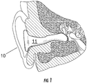
- FIG. 1-2 A first embodiment of a device 10 of the present invention inserted in the ear of a human wearer is schematically illustrated in Figures 1-2 (the anatomical portion of the figures is adapted from Figure 2 of Grams et al., US Patent No. 4,244,377 ).
- the device 10 is an in-ear device for delivering vestibular stimulation to a human wearer.
- the device comprises an ear insert 11 so dimensioned as to be insertable into the ear canal 20 of a wearer.
- the ear insert has an inner portion 12, with the inner portion preferably having a length dimension at least as great as a major portion of the length dimension of the ear canal of the wearer (e.g., a length at least 50, 60, 70, or 80 percent that of the length dimension of the ear canal of the wearer).
- the device disclosed herein incorporates active elements onto the ear insert 11 for engaging the ear canal 20 and thereby accessing the individual's vestibular system.
- active elements means those portions, regions, or components of the vestibular stimulation device 10 that induce a change in the ear canal 20 of the wearer. The change can be any physiological, structural, or physical response in the ear canal 20 capable of affecting the vestibular system of the individual.
- active elements includes, but is not limited to, temperature elements such as thermometers, thermoelectric transducers, electrodes, and other components useful in controlling the vestibular system.
- thermoelectric transducer 30 is mounted on the ear insert inner portion 12.
- Any suitable thermoelectric device or transducer can be used to carry out the present invention, including but not limited to those described in US Patent Nos. 7,205,675 ; 7,098,393 ; 7,024,865 ; and 5,974,806 ; and in US Patent Application Publication No. 2004/0199266 . See also S. Riffat and X. Ma, Thermoelectrics: A review of present and potential applications, Applied Thermal Engineering 23, 913-935 (2003 ).
- the transducer can be an electrothermal textile transducer, including but not limited to those described in US Patent Nos.
- thermoelectric transducers in all shapes and sizes, including but not limited to spiral and helical shapes.
- thermoelectric transducers may be mounted on an elongated flexible strip by any suitable technique, including but not limited to those described in Hiller et al., U.S. Patent No. 7,147,739 .
- the transducer can be a mechanical or piezoelectric transducer. Examples include but are not limited to both piezoelectric devices and zinc-oxide nanowire nanogenerators. See, e.g., X. Wang, "Direct-Current Nanogenerator Driven by Ultrasonic Waves," Science 316: 102-105 (April 6, 2007 ). Z.
- Thin film thermoelectric devices or transducers are preferred as transducers in some embodiments, including but not limited to the thin film thermoelectric devices described in US Patent No. 6,300,150 and US Patent Application Publication Nos. 2007/0028956 and 2006/0086118 .
- Such thin film thermoelectric devices may also advantageously incorporate a temperature sensing function, so that temperature sensing can be accomplished through the same device without the need for a separate temperature sensor.
- the ear insert 11 can be formed of any suitable material, including flexible materials (particularly where the ear insert is shaped in conformance with the ear canal of the subject) and rigid materials (e.g., when a more cushioning sleeve is utilized).
- the ear insert 11 can be formed by any suitable technique, such as molding or casting, with the thermoelectric device 30 or transducer (and any associated wires or leads) cast or molded in place in accordance with conventional techniques.
- the ear insert 11 can in some embodiments have a canal formed therein to facilitate or permit natural ventilation of the ear, as described in US Patent No. 6,819,770 to Niederdrank . If desired for some embodiments, the ear insert 11 can also include an acoustic transducer for delivering auditory or sound stimuli to the wearer.
- a sleeve or sheath 40 may be connected to ( e.g. , removably connected to; permanently connected to; or formed on) the ear insert inner portion 12.
- the sleeve may have a closed medial end portion 41 and an open outer end portion 42.
- the sleeve 40 has an inner surface portion configured 45 to conformably engage the ear insert inner portion 12, and an outer surface portion 46 configured to conformably engage the ear canal 20 of the wearer, Hence, heat can be conducted between (that is, to or from) each of the at least one thermoelectric transducers 30 and the ear canal 20 through the sleeve 40 to deliver caloric vestibular stimulation to the wearer.
- the ear insert inner portion 12 has a shape (i.e., a preformed shape) that corresponds to the ear canal 20 of the wearer.
- the sleeve 40 is configured to correspond to the shape of the ear insert inner portion 12, but conforms to the ear canal 20 of the wearer only when mounted on the sleeve insert inner portion 12.
- the ear insert inner portion 12 does not have a shape that corresponds to the shape of the ear canal 20 of the wearer, but the sleeve outer surface portion 46 instead has a shape ( i.e., a preformed shape), that corresponds to the ear canal of the wearer.
- Both embodiments provide, when assembled, a sleeve inner surface portion 45 that conformably engages the ear insert inner portion 12, and an outer surface portion 46 that conformably engages the ear canal 20 of the wearer.
- heat can be conducted between each of the at least one thermoelectric transducers 30 and the ear canal 20 through the sleeve 40, as discussed above.
- the sleeve 40 can comprise, consist of, or consist essentially of any suitable elastic and/or compressible material, such as a polymer, a textile (woven or non-woven) or a composite thereof.
- the polymer comprises a hydrogel polymer, a thermally conductive resin, and/or a viscoelastic polymer (it being understood that some but not all viscoelstic polymers will be hydrogel polymers; and some but not all hydrogel polymers will be viscoelastic polymers).
- suitable hydrogel polymers including biodegradable or bioerodable hydrogel polymers, and stable hydrogel polymers (e.g. , silicone hydrogel polymers) are known. Examples include but are not limited to those described in US Patent Nos.
- Suitable viscoelastic polymers include but are not limited to those described in, for example, US Patent Nos. 7,217,203 ; 7,208,531 ; and 7,191,483 .
- An ester-based viscoelastic memory foam such as used in the heating pad systems described in US Patent No. 7,176,419 is among those suitable for use in making sleeves of the present invention.
- the sleeve 40 has a thermal conductivity of from 0.1 to 50 W/m x K; and a hardness of from 0 to 50 on the Shore A scale.
- the sleeve 40 can be made by any suitable technique such as molding, casting, etc. While in some preferred embodiments the sleeve 40 is removable, in other embodiments that sleeve is formed on, integrally formed with, or otherwise permanently connected to the ear insert 11.
- the sleeve 40 can be open at both the medial 41 (closest to the ear drum) and outer ends 42 thereof, or open at the outer end 42 only.
- the sleeve 40 is preferably open at both the proximal and distal ends of the canal.
- the sleeve 40 may be transparent or tinted with a pigment, in whole or in part such as in one or more defined locations on the sleeve ( e.g ., the medial portion, the outer portion, the upper portion, the lower portion, the front portion, the back portion) to provide an indicator of whether the sleeve is for a left or right ear canal device, an indicator of size of the sleeve, an indicator of how the sleeve should be oriented on the insert, etc.
- a pigment in whole or in part such as in one or more defined locations on the sleeve (e.g ., the medial portion, the outer portion, the upper portion, the lower portion, the front portion, the back portion) to provide an indicator of whether the sleeve is for a left or right ear canal device, an indicator of size of the sleeve, an indicator of how the sleeve should be oriented on the insert, etc.
- the ear insert 11 can optionally include an identifier associated therewith for indicating whether said ear insert is configured for insertion into a left or right ear canal.
- the sleeve 40 can optionally include an identifier associated therewith for indicating whether said sleeve 40 is configured for: (i) insertion into a left or right ear canal, or (ii) engagement on said ear insert inner portion when said ear insert is configured for insertion into a left or right ear canal.
- Such identifiers can be printed, stamped, or molded symbols such as "L" for left and "R” for right; color coding for left and right; etc.
- the ear insert 11 has an outer portion 13, the outer portion 13 configured to overlie at least a portion ( e.g. , some or all) of the external ear 22 of a wearer. This creates an external appearance, when worn, similar to that of a half-shell or full-shell hearing aid.
- any suitable configuration can be utilized, as further shown in Figures 9-10 , in which the device is configured to be positioned in the canal or completely in the canal of the wearer. Note also in Figure 10 that the device medial portion 14 does not abut the eardrum, as would the medial portion 14 of the device of Figure 9 .
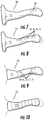
- FIGS 7-12 illustrate various transducer arrangements in devices of the present invention. While a single thermoelectric transducer 30 can be used, in some embodiments it is preferable to include at least two, three, or four (or more) separately controllable thermoelectric transducers 30a, 30b, 30c, 30d, which can be spaced apart from one another on the ear insert inner portion 12. As shown in Figures 7-9 , the transducers can be positioned longitudinally along the insert 11; as shown in Figure 10 , the transducers 30 can be positioned laterally along the insert 11. Other positionings, such as angled positionings, and combinations of the foregoing, can also be used. Further, while the transducers are depicted as rectangular in shape, any suitable regular or irregular shape can be used.
- FIGS 13-14 illustrate a further embodiment of the present invention, in which an external housing 50 is connected to the ear insert by a bridge member 51 (here, in the shape of a tube).
- the external housing 50 is configured for positioning behind the ear of a wearer.
- the housing 50 can contain a computerized control module, control circuitry, a power supply such as a battery, controls such as an on-off switch 52, etc.
- the housing has an external transducer 53 mounted on the medial surface 54 thereof, which external transducer can deliver thermal, electric, or mechanical stimuli to the wearer at subthreshhold (e.g.
- the external transducer can be positioned on the housing so that it contacts the wearer on or adjacent to the mastoid process 25 of the wearer.
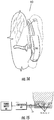
- Figure 15 schematically illustrates a device of the present invention operatively associated with a controller 60, which controller is in turn operatively associated with a power supply 61.
- the controller and power supply can be contained within the device (e.g., in an external housing as described in connection with Figures 13-14 above), in a belt-worn or other housing, connected to a stationary unit such as a personal computer, or in any other suitable configuration.
- the controller includes a computerized control module 70 programmed with computer instructions (i.e., software) that controls the magnitude, duration, wave pattern, and other attributes of the vestibular stimulation.
- thermoelectric transducer 30a, 30b, 30c each of which is operatively associated with the controller by a separate lead 31a, 31b, 31c, is activated for a time and to a temperature sufficient to deliver caloric vestibular stimulation to the wearer.
- An adjustable or programmable control module 70 can be utilized to optimize stimulation for a particular wearer, and for a particular purpose or condition.
- the activating step can comprise separately and selectively activating the at least two separately controllable thermoelectric transducers (e.g., by activating only one or two thereof, by heating one transducer and cooling another; by sequentially activating transducers; by activating different transducers to different degrees; combinations of some or all of the foregoing, etc.) Patterns of separate and selective activation can be preprogrammed, can be determined empirically, can be optimized by the wearer or a programmer (such as a clinician) in a programming session with the wearer, etc.
- the control module can be part of a multimodal stimulation system for creating a "virtual environment" for the wearer, such as described in US Patent No. 5,762,612 to Campbell .
- the device can incorporate sensors or monitoring probes for positioning in the ear canal, such as described in Fischer et al., US Patent Application Publication No. 2007/0112277 (May 17, 2007 ) and in J. Fraden, US Patent Application Publication No. 2005/0209516 (Sept. 22, 2005 ).
- Subjects or wearers for the devices of the present invention are often, but are not limited to, human subjects, including both male and female subjects at any stage of development (e.g., juvenile, adolescent, adult, and geriatric subjects). While the shape of ears and ear canals 20 thus will vary among subjects or wearers, and different sizes and combinations of ear inserts and sleeves will likely be necessary to accommodate different wearers, an optimal set of inserts and sleeves can be developed through the use of statistical shape analysis ( see, e.g., R.
- an insert 11 of the invention is preformed to conform to, and hence conformably engage, the ear canal 20 of a particular wearer.
- a preformed insert 11 can be produced by forming an ear impression, which ear impression can then be used for casting in analogous manner as described in US Patent No. 6,249,587 , or can instead be scanned and utilized for subsequent casting, three-dimensional ink-jet printing, and/or other three dimensional construction (via deposition or removal of materials), as described in US Patent Nos. 7,162,323 ; and 6,986,739 (see also S. Fuller, "Ink-jet printed nanoparticle micro electromechanical systems", Journal of Microelectromechanical Systems 11, 54-60 (2002 ).
- the need for a sleeve may be obviated, although it is preferred that the ear insert itself comprise or be formed of a soft resilient material (e.g., having a hardness of from 0 to 50 on the Shore A scale).
- a soft resilient material e.g., having a hardness of from 0 to 50 on the Shore A scale.
- the present invention is useful for a variety of different purposes.
- the device can be used to enhance spatial and verbal memory function, as described in D. Bachtold et al., supra.
- the device can be used, individually or in pairs, to augment or control a patient's respiratory function, induce sleep, and/or counteract dizziness or vertigo, as described in US Patent No. 6,748,275 to Lattner .
- the device can be used to treat neurological disorders, headache (including migraine headache), seasickness and travel sicknesses, as described in O. Kolev, supra , and US Patent Application Publication No. 2003/0195588 to Fischell et al.
- the device can be used to improve or enhance autonomic and/or motor responsiveness in patients afflicted with central neurodegenerative disorders such as Parkinson's disease, as described in Y. Yamamoto et al., supra.
- the device can be utilized to treat pain such as thalamic pain syndrome, as described in V. Ramachandran et al., supra.
- the device can be utilized in a "virtual environment" educational, entertainment or training system, such as described in US Patent No. 5,762,612 to Campbell .
- the device 10 of this invention is useful for diagnostic purposes. Instead of using the previously noted water caloric tests to determine levels of consciousness, the in-ear device disclosed herein is more efficient, avoids water spills, and provides adjustable ranges of stimulation. Levels of consciousness are not the only diagnostic measures possible with the device 10.
- a health care worker using the device of this invention would also be equipped to combine vestibular stimulation with brain scans to determine which areas of the brain are actively engaged at any given time. By comparing a healthy brain exposed to vestibular stimulation with a patient's brain scan during vestibular stimulation, the medical professional would quickly notice areas showing different levels of activity. The differences could be crucial in identifying regions of the patient's brain that are in a diseased state. Such information allows for more accurate diagnoses and more rapid medical intervention.
- Phantom limb pain is a condition in which a patient experiences ongoing sensations that an amputated or missing limb is still present. The sensations often present as pain.
- Modern research indicates that the region of the brain associated with phantom limb pain is the thalamus. Brown, C.J., "Phantom of the Thalamus,” Canadian Medical Association Journal 158:711 (1998 ).
- the device 10 described herein is useful for tracking, monitoring, and adjusting an individual's circadian rhythms. It is well known that body temperature fluctuates in a circadian cycle. In one embodiment, therefore, the device 10 controls the circadian temperature cycle of an individual by providing a stimulus through the individual's ear.
- the device according to this embodiment includes an ear insert that is shaped similarly to and engages the individual's ear canal. A temperature element attached to the insert measures changes in the individual's body temperature over time, preferably during a non-diseased state.
- the system of this invention tracks the temperature readings over a time period of at least 24 hours and records the measurements as a data set. These measurements are useful in establishing a baseline temperature circadian cycle that is unique for that individual.
- the ear insert 11 further includes at least one thermoelectric transducer 30 attached to the insert 11 for providing caloric vestibular stimulation to the individual.
- the thermoelectric transducer 30 may be contained entirely within the insert 11 or may be attached to the separate sleeve 40 described above.
- the thermoelectric transducer 30 used in the device 10 may be a thermoelectric cooler common in the industry today.
- the thermoelectric transducer 30 is capable of providing caloric stimulation to the individual's inner ear by allowing for the transfer of heat to and from the ear canal 20, thereby raising and lowering the temperature of the ear canal 20 as desired.
- the ear canal serves as a useful conduit to the individual's vestibular system.
- the above-noted temperature 75 element measures the body temperature of the individual wearing a device.
- the temperature element 75 allows for monitoring the circadian temperature cycle for that individual.
- the monitoring function is accomplished by a computerized control module 70 in electronic communication with the insert, the temperature element 75, and the transducer 30.
- the control module 70 includes instructions, or computer commands, stored thereon for adjusting the rate of heat transfer between the transducer and individual's ear canal. The rate adjustment occurs in response to signals from the control module 70.
- the control module 70 may be located in the above-described outer portion 13 of the overall device 10; the outer portion 13 conveniently fits around the outer ear. In other embodiments, the control module 70 may be included in or combined with any peripheral device that is capable of achieving a therapeutic result (i.e., the control module 70 may be housed in a personal computer or other medical device as part of an overall medical system).
- the temperature element 75 signals transmitted back to the control module 70 may be utilized in real time for immediately adjusting the output from the control module 70.
- the control module 70 may store historical body temperature data to establish a circadian temperature cycle over a known period of time.
- the control module 70 may be programmed to regulate the vestibular stimulation directed to an individual at a particular point in the circadian cycle some time in the future.
- the device 10 and system according to this invention function to provide caloric stimulation to an individual's vestibular system, thereby raising and lowering the temperature of the ear canal.
- the control module 70 can be programmed to apply vestibular stimulation according to previously set instructions and functions such as ramping functions, square wave functions, and other mathematical algorithms.
- the device incorporates a time-keeping element, which may be a simple clock 80.
- the clock 80 is also in electronic communication with the computerized control module 70, as well as other components that are part of the overall vestibular stimulation system.
- the clock 80 of this device 10 allows the user to program the control module 70 in a way that tracks an individual's physiological data in the time domain, thereby allowing for planned therapeutic intervention at a certain time, including the present.
- the device 10 includes a mechanism for adjusting the time on the clock 80 to account for natural time changes such as daylight savings time and crossing time zones during travel.
- the mechanism for adjusting the time may be simple directional arrows for up and down time changes or more sophisticated electronics useful in the art of time keeping.
- the device 10 is equipped to maintain the current time in which an individual presently resides.
- the control module 70 can include instructions programmed into associated software that account for phase shifts in the individual's circadian cycle. The most common phase shift occurs in the time domain, and the control module, in conjunction with the associated clock, includes programs capable of providing vestibular stimulation in a way that synchronizes the individual's circadian cycle with the current time zone.
- the device 10 is useful for alerting an individual or that individual's health care provider that the circadian cycle currently in place in the individual's body does not match the real geographical time (i.e. local time) that the individual is currently experiencing.
- the device described herein incorporates artificial intelligence sufficient to compare an individual's baseline circadian cycle, real-time circadian cycle, and current geographical time in a way that allows the individual to adjust medical interventions as appropriate.
- certain medications work optimally at a particular point in an individual's circadian temperature cycle.
- his or her health care provider can determine the time of day that the individual should take certain medications. If that individual's circadian cycle is shifted at any point due to significant changes in routine, the prescribed time of dosing may become inaccurate. The same is true when the individual crosses time zones during travel.
- the inner ear device described herein is capable of numerous interventions during any of these situations. First, the device 10 uses feedback from sensors ( 30, 75 ) engaging the ear canal 20 to alert the individual that the circadian cycle for a certain physiological parameter, such as temperature, has shifted, and the individual should shift the time for taking a certain medicine appropriately.
- the health care provider may determine that circadian shifts away from the baseline are detrimental to the patient's well-being. In this case, the health care provider needs a way to re-set the patient's circadian clock to match geographical time.
- the control module 70 within the device 10 may be programmed to provide vestibular stimulation in a way that actually moves and changes that individual's circadian cycle. As noted above, the most direct route to resetting the circadian cycle is through the SCN region of the brain, because the vestibular system is a direct conduit to the body's master clock in the SCN.
- One goal of this invention is to provide a mechanism and computerized method of stimulating an individual's brain by directing energy in the form of electrical current, heat transfer, light, pressure differentials, and other sources to the vestibular system. This energy is ultimately transferred through the vestibular system to the brain.
- computer software instructions can be incorporated into the device 10 to direct the output from elements ( 30, 75 ) engaging the ear canal 20.
- the computerized control module 70 directs heat output from a thermoelectric transducer 30 and/or electrical output from an electrode 85 at a magnitude and time duration that actually affects the brain chemistry, blood chemistry, and circadian cycle for that individual.
- different patterns or waveforms may be used. These patterns include uniform pulse, random pulse, amplitude modulated pulses, and ramped pulses.
- Regions of the brain that may be affected via vestibular stimulation include, but are not limited to, the SCN, the cerebellar fastigial nucleus, the insula cortex, and regions of the brain adjacent to these.
- the computerized control module 70 and the associated elements of the ear insert 11 can be programmed to induce biochemical and other physiological changes in the individual's body.
- the ear insert 11 can be programmed to induce serotonin output, ascorbic acid output, acetylcholine release, histamine release, and/or the production of heat shock proteins with therapeutic value.
- the device includes the ear insert 11, thermoelectric transducer 30, electrode 85, and computerized control module 70 described above.
- the active elements ( 30, 70, 85 ) on the insert 11, including any transducer 63 or electrode 64, occupy adjustable positions for greater control over the device 10.
- the ability to adjust the position of the active elements on the insert allows for greater flexibility in directing stimulation in a way that is customized for that person. Minor changes in the direction and location of output can have large consequences for different individuals.
- one embodiment of the device includes modular portions 60-62 that fit together and come apart for greater variety in positioning the output.
- the modular structure shown in Figures 16 and 17 also allows for interchangeable ear inserts to be used with a single control module housed in the outer portion of the device.
- Interchangeable ear inserts 62 are useful to allow for a variety of modifications in keeping with the scope of this invention. For example, a single individual might require therapy with fewer or greater numbers of any active element. As noted herein, the device 10 includes the flexibility to increase or reduce the number of electrodes 64, transducers 63, or other active elements necessary to achieve a desired result. Also, the modular nature of the device shown in Figures 16 and 17 allows for portions or pieces of the device 10 to be replaced without replacing the whole device. An ear insert 62 might be less expensive to replace than the computerized control module.
- Figures 16 and 17 illustrate schematically one embodiment of a modular vestibular stimulation device in which the active elements, located on either the ear insert 11 portion, or possibly a sleeve 40 as described above, are attached to an outer portion 50 via standard electrical connectors.
- the vestibular stimulation device 10 is operational as an individualized piece of equipment worn by a single user, similar to the way a person wears a hearing aid. In different embodiments, however, the device 10 can be incorporated into a larger medical system.
- the computerized control module 70 connects to peripheral equipment for added functionality.
- the device 10 is part of a larger therapeutic system that includes other devices for monitoring physiological parameters. Without limiting the types of peripheral equipment connecting to the device described herein, one useful peripheral sensor measures galvanic skin resistance. Skin resistance is a significant factor in estimating certain physiological and emotional changes that an individual is experiencing. When data tracking skin resistance are combined with data tracking a circadian cycle, such as the temperature cycle, the result is a broader, more holistic approach to treating an individual.
- the device 10 particularly the computerized control module 70, processes data gathered by peripheral devices, such as a galvanic skin resistance, and adjusts device 10 output accordingly.
- peripheral devices such as a galvanic skin resistance
- the device is useful for practicing a method of delivering vestibular stimulation to an individual's brain.
- the method includes (i) arranging a thermal transducer 30 and an electrode 85 on an ear insert 11 in a position to stimulate the vestibular system of the wearer, (ii) electronically connecting the transducer 30 and the electrode 85 to a controller 38, and (iii) supplying the controller 38 with galvanic skin resistance data and temperature data from the individual.
- the device 10 activates the transducer 30 and the electrode 85 via the controller 38.
- the transducer regulates heat exchange within the ear canal for a time and to a temperature sufficient to deliver vestibular stimulation to the individual.
- the electrode 85 provides electrical stimulation to the vestibular system according to pre-set functions within the controller 38.
- the controller 38, the transducer 30, and the electrode 85 deliver vestibular stimulation, wherein the vestibular stimulation is selected from caloric stimulation, electrical stimulation, and combinations of each.
- the method further includes the step of measuring physiological changes in the individual, wherein the physiological changes are selected from the group consisting of brain chemistry changes and blood chemistry changes.
- the step of measuring physiological changes can be selected from the group consisting of circadian temperature cycle time shifts, ascorbic acid production, serotonin production, histamine production, acetylcholine production, and heat shock protein production.
- the device 10 of this invention effectively provides vestibular stimulation, and therefore direct brain tissue stimulation, in numerous embodiments that include combinations and sub-combinations of the various elements described above. It is entirely within the scope of the device for the ear insert to be used with or without the above-described sleeve 40, which in one embodiment is removable and disposable. Similarly, the device 10 may incorporate other features that assist in providing a therapeutic result. For example, certain therapies may be optimized if the active elements of the device are in a particular position, and other therapies may be optimized if the individual's head is in a particular position.
- the device may include an inclinometer that measures the angle at which the individual's head is positioned in relation to a known norm. In a preferred embodiment, the device incorporates an incline indicator to show the individual or a health care provider the current angle at which an individual's head is positioned. Naturally, the inclinometer includes a calibration device to adjust for a particular individual's natural head position.
- the device disclosed herein incorporates standard features that are commonly used in hearing aids and other inner ear devices known today. For instance, given the fact that vestibular stimulation will likely not be administered around the clock, the device incorporates an automatic shutdown mode enabled during extensive periods of inactivity. Other useful features available for the device include battery operation and padding for the outer portion worn on the outer ear.
- the housing 50 for the computerized control module 70 may be available in stylized and appropriately colored models to accommodate the tastes of the individual wearing it.
Landscapes
- Health & Medical Sciences (AREA)
- Veterinary Medicine (AREA)
- Life Sciences & Earth Sciences (AREA)
- Animal Behavior & Ethology (AREA)
- General Health & Medical Sciences (AREA)
- Public Health (AREA)
- Engineering & Computer Science (AREA)
- Biomedical Technology (AREA)
- Vascular Medicine (AREA)
- Heart & Thoracic Surgery (AREA)
- Rehabilitation Therapy (AREA)
- Radiology & Medical Imaging (AREA)
- Nuclear Medicine, Radiotherapy & Molecular Imaging (AREA)
- Physics & Mathematics (AREA)
- Thermal Sciences (AREA)
- Otolaryngology (AREA)
- Epidemiology (AREA)
- Pain & Pain Management (AREA)
- Physical Education & Sports Medicine (AREA)
- Measuring And Recording Apparatus For Diagnosis (AREA)
- Electrotherapy Devices (AREA)
- Thermotherapy And Cooling Therapy Devices (AREA)
Claims (12)
- Vorrichtung zum Bewirken einer vestibulären Stimulation bei einer Person, umfassend:(a) einen Ohreinsatz(b) mindestens einen thermoelektrischen Wandler, welcher im Ohreinsatz eingeschlossen ist und welcher in der Lage ist, das vestibuläre System der Person zu beeinflussen, indem er in der Lage ist, die Temperatur des Ohrkanals der Person zu erhöhen und zu reduzieren; und(c) eine Steuerung, welche mit dem einen oder den mehreren thermoelektrischen Wandlern verbunden und konfiguriert ist, um den einen oder die mehreren thermoelektrischen Wandler zu aktivieren, um eine kalorische vestibuläre Stimulation des vestibulären Systems der Person zu bewirken,wobei die Steuerung ein Steuermodul umfasst, welches konfiguriert ist, um die Größe, die Dauer und das Wellenmuster der vestibulären Stimulation zu steuern, dadurch gekennzeichnet, dass der Ohreinsatz so dimensioniert ist, dass er in den Ohrkanal der Person eingesetzt werden kann, und der Einsatz einen Innenabschnitt umfasst, welcher eine Form aufweist, die dem Ohrkanal der Person entspricht.
- Vorrichtung nach Anspruch 1, wobei der mindestens eine thermoelektrische Wandler eine Mehrzahl von thermoelektrischen Wandlern umfasst.
- Vorrichtung nach Anspruch 2, wobei jeder der Mehrzahl von thermoelektrischen Wandlern separat steuerbar ist.
- Vorrichtung nach Anspruch 3, wobei das Aktivieren der thermoelektrischen Wandler das separate und selektive Aktivieren der thermoelektrischen Wandler umfasst.
- Vorrichtung nach einem der Ansprüche 2 bis 4, wobei jeder der Mehrzahl von thermoelektrischen Wandlern der Steuerung über einen getrennten Anschluss betriebsmäßig zugeordnet ist.
- Vorrichtung nach einem der Ansprüche 1 bis 5, wobei jeder thermoelektrische Wandler einen thermoelektrischen Dünnschichtwandler umfasst.
- Vorrichtung nach einem der Ansprüche 1 bis 6, ferner umfassend mindestens eine Elektrode, welche am Ohreinsatz befestigt ist, um das vestibuläre System der Person elektrisch zu stimulieren, wobei die Steuerung der einen oder den mehreren Elektroden betriebsmäßig zugeordnet und konfiguriert ist, um die eine oder die mehreren Elektroden zu aktivieren, um eine elektrische Stimulation des vestibulären Systems der Person zu bewirken.
- Vorrichtung nach Anspruch 7, wobei die mindestens eine Elektrode eine Mehrzahl von Elektroden umfasst.
- Vorrichtung nach einem der Ansprüche 7 oder 8, wobei die Steuerung konfiguriert ist, um elektrische Impulse abzugeben.
- Vorrichtung nach einem der Ansprüche 1 bis 9, ferner umfassend einen oder mehrere Sensoren.
- Vorrichtung nach Anspruch 10, wobei das Steuermodul konfiguriert ist, um Daten zu verarbeiten, die durch den einen oder die mehreren Sensoren gesammelt werden, und um den Ausgang der Vorrichtung entsprechend einzustellen.
- System umfassend die Vorrichtung nach einem der Ansprüche 1 bis 11.
Applications Claiming Priority (3)
| Application Number | Priority Date | Filing Date | Title |
|---|---|---|---|
| US95370007P | 2007-08-03 | 2007-08-03 | |
| EP08827154.9A EP2190400B1 (de) | 2007-08-03 | 2008-08-01 | Vestibular-stimulationsgerät |
| PCT/US2008/071935 WO2009020862A2 (en) | 2007-08-03 | 2008-08-01 | Vestibular stimulation apparatus and associated methods of use |
Related Parent Applications (1)
| Application Number | Title | Priority Date | Filing Date |
|---|---|---|---|
| EP08827154.9A Division EP2190400B1 (de) | 2007-08-03 | 2008-08-01 | Vestibular-stimulationsgerät |
Publications (2)
| Publication Number | Publication Date |
|---|---|
| EP2829259A1 EP2829259A1 (de) | 2015-01-28 |
| EP2829259B1 true EP2829259B1 (de) | 2019-04-10 |
Family
ID=40278876
Family Applications (2)
| Application Number | Title | Priority Date | Filing Date |
|---|---|---|---|
| EP14163419.6A Active EP2829259B1 (de) | 2007-08-03 | 2008-08-01 | Vorrichtung zur vestibulären Stimulation |
| EP08827154.9A Active EP2190400B1 (de) | 2007-08-03 | 2008-08-01 | Vestibular-stimulationsgerät |
Family Applications After (1)
| Application Number | Title | Priority Date | Filing Date |
|---|---|---|---|
| EP08827154.9A Active EP2190400B1 (de) | 2007-08-03 | 2008-08-01 | Vestibular-stimulationsgerät |
Country Status (5)
| Country | Link |
|---|---|
| US (1) | US8262717B2 (de) |
| EP (2) | EP2829259B1 (de) |
| JP (1) | JP5425776B2 (de) |
| AU (1) | AU2008284042B2 (de) |
| WO (1) | WO2009020862A2 (de) |
Families Citing this family (60)
| Publication number | Priority date | Publication date | Assignee | Title |
|---|---|---|---|---|
| US8425583B2 (en) | 2006-04-20 | 2013-04-23 | University of Pittsburgh—of the Commonwealth System of Higher Education | Methods, devices and systems for treating insomnia by inducing frontal cerebral hypothermia |
| US12290640B2 (en) | 2006-04-20 | 2025-05-06 | University of Pittsburgh—of the Commonwealth System of Higher Education | Noninvasive, regional brain thermal stimulation for inducing relaxation |
| US11684510B2 (en) | 2006-04-20 | 2023-06-27 | University of Pittsburgh—of the Commonwealth System of Higher Education | Noninvasive, regional brain thermal stimuli for the treatment of neurological disorders |
| US9211212B2 (en) | 2006-04-20 | 2015-12-15 | Cerêve, Inc. | Apparatus and method for modulating sleep |
| US9492313B2 (en) | 2006-04-20 | 2016-11-15 | University Of Pittsburgh - Of The Commonwealth System Of Higher Education | Method and apparatus of noninvasive, regional brain thermal stimuli for the treatment of neurological disorders |
| WO2007124012A1 (en) | 2006-04-20 | 2007-11-01 | University Of Pittsburgh | Method and apparatus of noninvasive, regional brain thermal stimuli for the treatment of neurological disorders |
| JP2008048067A (ja) * | 2006-08-11 | 2008-02-28 | Matsushita Electric Works Ltd | 補聴器 |
| US8696724B2 (en) | 2007-01-11 | 2014-04-15 | Scion Neurostim, Llc. | Devices for vestibular or cranial nerve stimulation |
| US8267983B2 (en) | 2007-01-11 | 2012-09-18 | Scion Neurostim, Llc. | Medical devices incorporating thermoelectric transducer and controller |
| US8603152B2 (en) | 2009-12-18 | 2013-12-10 | Scion Neurostim, Llc | Devices and methods for vestibular and/or cranial nerve stimulation |
| US20110130786A1 (en) * | 2009-12-01 | 2011-06-02 | Ascentia Health, Inc. | Method for Treating Headaches with Intra-Aural Devices |
| US20110245902A1 (en) * | 2010-03-30 | 2011-10-06 | Katz Jay W | Method for relieving motion sickness and related apparatus |
| DE102010015278B4 (de) | 2010-04-15 | 2012-07-26 | Cerbomed Gmbh | Elektrodenanordnung zur zumindest teilweisen Einbringung in einen Gehörkanal eines Menschen |
| WO2011161562A1 (en) | 2010-06-22 | 2011-12-29 | Koninklijke Philips Electronics N.V. | System and method of delivering vestibular stimulation customizable to individual subjects |
| US10512564B2 (en) | 2010-12-16 | 2019-12-24 | Scion Neurostim, Llc | Combination treatments |
| US9744074B2 (en) | 2010-12-16 | 2017-08-29 | Scion Neurostim, Llc | Combination treatments |
| JP6580298B2 (ja) * | 2010-12-16 | 2019-09-25 | サイオン・ニューロスティム,リミテッド・ライアビリティ・カンパニー | 前庭刺激デバイス及び前庭刺激システム |
| US10537467B2 (en) | 2010-12-16 | 2020-01-21 | Scion Neurostim, Llc | Systems, devices and methods for bilateral caloric vestibular stimulation |
| US8718307B2 (en) * | 2011-03-11 | 2014-05-06 | Daniel R. Schuamier | Hearing aid apparatus |
| EP2550993B1 (de) * | 2011-03-29 | 2014-12-10 | Valkee Oy | Vorrichtung zur Veränderung des Dopaminspiegels |
| US8465531B2 (en) | 2011-03-29 | 2013-06-18 | Valkee Oy | Light therapy modality |
| JP5926511B2 (ja) * | 2011-08-11 | 2016-05-25 | 株式会社アドバンス | 美容・健康モニタリングシステム |
| US9191761B2 (en) * | 2012-01-30 | 2015-11-17 | Etymotic Research, Inc. | Hearing testing probe with integrated temperature and humidity sensors and active temperature control |
| WO2013128293A2 (en) | 2012-02-28 | 2013-09-06 | Soza Ana Maria | Methods, apparatuses and systems for diagnosis and treatment of mood disorders |
| JP2014076159A (ja) * | 2012-10-10 | 2014-05-01 | Kiyoshi Kano | 耳穴温度調節具 |
| JP6352303B2 (ja) | 2013-01-02 | 2018-07-04 | イービービー セラピュティクス インコーポレイテッド | 睡眠促進システム |
| US10569084B2 (en) | 2013-03-01 | 2020-02-25 | The Regents Of The Universit Of California | Method and system for altering body mass composition using galvanic vestibular stimulation |
| ES2943637T3 (es) | 2013-03-01 | 2023-06-15 | Univ California | Procedimiento cosmético para alterar la composición de la masa corporal mediante estimulación vestibular galvánica |
| US10675465B2 (en) | 2013-03-01 | 2020-06-09 | The Regents Of The University Of California | Methods for treatment of disease using galvanic vestibular stimulation |
| US9039639B2 (en) * | 2013-06-28 | 2015-05-26 | Gbs Ventures Llc | External ear canal pressure regulation system |
| US10251790B2 (en) | 2013-06-28 | 2019-04-09 | Nocira, Llc | Method for external ear canal pressure regulation to alleviate disorder symptoms |
| US12396892B2 (en) | 2013-06-28 | 2025-08-26 | Nocira, Llc | External ear canal pressure regulation device |
| EP3054800B1 (de) | 2013-10-11 | 2025-01-29 | EMBR Labs IP LLC | Verfahren und vorrichtungen zur temperaturmanipulation |
| US10182937B2 (en) * | 2013-10-11 | 2019-01-22 | Embr Labs Inc. | Methods and apparatuses for manipulating temperature |
| WO2016149117A1 (en) | 2015-03-13 | 2016-09-22 | Embr Labs Inc. | Methods and apparatuses for manipulating temperature |
| CN105232930A (zh) * | 2015-08-17 | 2016-01-13 | 陈洪凯 | 人体穴位药磁热复合健身丸及其制作、使用方法 |
| EP3344200B1 (de) | 2015-09-04 | 2023-03-29 | Scion NeuroStim, Inc. | Systeme, vorrichtungen und verfahren zur galvanisch-vestibulären stimulation mit hüllkurvenmodulation |
| US10760566B2 (en) | 2016-07-22 | 2020-09-01 | Nocira, Llc | Magnetically driven pressure generator |
| WO2018157143A1 (en) | 2017-02-27 | 2018-08-30 | Nocira, Llc | Ear pumps |
| US20180250192A1 (en) * | 2017-03-02 | 2018-09-06 | Zok Relief, LLC | Method and apparatus for relieving headache symptoms |
| CN111050840A (zh) * | 2017-07-07 | 2020-04-21 | 加利福尼亚大学董事会 | 用于使用前庭电刺激来改变体重组成的方法和系统 |
| CA3091956A1 (en) * | 2018-03-07 | 2019-09-12 | Scion Neurostim, Llc | Systems, devices and methods for neurostimulation |
| CN109011099B (zh) * | 2018-06-13 | 2021-03-05 | 陕西理工大学 | 一种幼儿挖耳助眠装置 |
| WO2019246456A1 (en) | 2018-06-22 | 2019-12-26 | Nocira, Llc | Systems and methods for treating neurological disorders |
| JP2020069272A (ja) * | 2018-11-01 | 2020-05-07 | 株式会社富士インダストリーズ | 生体データ測定装置およびその製造方法 |
| US20210046312A1 (en) * | 2019-08-13 | 2021-02-18 | Neurovalens, Ltd. | Devices, systems and methods for synchronous binaural vestibular nerve stimulation |
| US11241574B2 (en) | 2019-09-11 | 2022-02-08 | Bose Corporation | Systems and methods for providing and coordinating vagus nerve stimulation with audio therapy |
| US11235156B2 (en) | 2019-09-11 | 2022-02-01 | Bose Corporation | Wearable audio device with vagus nerve stimulation |
| EP4044906B1 (de) | 2019-10-15 | 2025-03-12 | Kandu Health, Inc. | Systeme und verfahren zur mehrgrössenhubdetektion |
| EP3825794A1 (de) | 2019-11-21 | 2021-05-26 | pro-micron GmbH | Verfahren für die überwachung und/oder vorhersage von bearbeitungsprozessen und/oder bearbeitungsergebnissen |
| WO2021262789A1 (en) | 2020-06-23 | 2021-12-30 | Bose Corporation | Haptic tinnitus therapeutic system |
| JP7570890B2 (ja) * | 2020-11-06 | 2024-10-22 | 小林製薬株式会社 | 睡眠促進具 |
| US20250281116A1 (en) * | 2021-04-14 | 2025-09-11 | Kandu Health, Inc. | Systems and methods for multivariate stroke detection |
| EP4384129A1 (de) * | 2021-08-10 | 2024-06-19 | Péus, Dominik | Vorrichtungen, systeme und verfahren zur herbeiführung von temperaturänderungen im innenohr und/oder labyrinth |
| EP4140401B1 (de) * | 2021-08-31 | 2025-09-17 | Starkey Laboratories, Inc. | Ohr-tragbare elektronische vorrichtung mit einem in-kanal-temperatursensor |
| EP4197586B1 (de) * | 2021-12-20 | 2025-01-29 | Hahn-Schickard-Gesellschaft für angewandte Forschung e. V. | Personalisiertes elektroden-interface zur aurikulären stimulation |
| JP7766340B2 (ja) * | 2022-04-28 | 2025-11-10 | 株式会社アテックス | 耳用温熱装置 |
| CN114869239A (zh) * | 2022-05-26 | 2022-08-09 | 中国人民解放军空军特色医学中心 | 一种前庭冷热气体刺激仪 |
| USD1069809S1 (en) | 2022-08-25 | 2025-04-08 | Kandu Health, Inc. | Display screen or portion thereof with graphical user interface |
| WO2025157820A1 (en) * | 2024-01-26 | 2025-07-31 | Sony Group Corporation | Apparatus and method for stimulating the vestibular system of a user, and head-mounted equipment |
Citations (1)
| Publication number | Priority date | Publication date | Assignee | Title |
|---|---|---|---|---|
| FR2795629A1 (fr) * | 1999-06-11 | 2001-01-05 | Dmds | Dispositif pour la realisation d'une anesthesie utilisant les proprietes anesthesiques du froid ou du chaud |
Family Cites Families (43)
| Publication number | Priority date | Publication date | Assignee | Title |
|---|---|---|---|---|
| US4190033A (en) | 1977-02-23 | 1980-02-26 | Foti Thomas M | Closed flow caloric test method |
| US4244377A (en) | 1978-10-19 | 1981-01-13 | Grams Guenter A | Ear probe for use in closed-loop caloric irrigation |
| US4449528A (en) * | 1980-03-20 | 1984-05-22 | University Of Washington | Fast pulse thermal cautery probe and method |
| US4860748A (en) * | 1988-02-23 | 1989-08-29 | Thermapeutics, Inc. | Thermal pattern generator for pain relief |
| US5190539A (en) * | 1990-07-10 | 1993-03-02 | Texas A & M University System | Micro-heat-pipe catheter |
| EP0821541A3 (de) | 1996-07-24 | 2004-06-02 | Bernafon AG | Ganz im Gehörgang zu tragendes Hörgerät, das durch Giessen eines Körpers individualisiert wird |
| FI964700A0 (fi) | 1996-11-26 | 1996-11-26 | Jukka Pekola | Mikroavkylningsapparat |
| US5762612A (en) | 1997-02-28 | 1998-06-09 | Campbell; Craig | Multimodal stimulation in virtual environments |
| USRE41801E1 (en) | 1997-03-31 | 2010-10-05 | Nextreme Thermal Solutions, Inc. | Thin-film thermoelectric device and fabrication method of same |
| US6135117A (en) | 1997-05-12 | 2000-10-24 | Cornell Research Foundation, Inc. | Non-ocular circadian clock resetting in humans |
| US6229123B1 (en) | 1998-09-25 | 2001-05-08 | Thermosoft International Corporation | Soft electrical textile heater and method of assembly |
| US6748275B2 (en) | 1999-05-05 | 2004-06-08 | Respironics, Inc. | Vestibular stimulation system and method |
| US6314324B1 (en) * | 1999-05-05 | 2001-11-06 | Respironics, Inc. | Vestibular stimulation system and method |
| AU2001243603B9 (en) | 2000-03-13 | 2006-09-07 | Biocompatibles Uk Limited | Tissue bulking and coating compositions |
| WO2001095841A2 (en) | 2000-06-14 | 2001-12-20 | American Healthcare Products,Inc. | Heating pad systems for patient warming |
| DE10064771A1 (de) | 2000-12-22 | 2002-07-11 | Wet Automotive Systems Ag | Textile Heizvorrichtung |
| US7098393B2 (en) | 2001-05-18 | 2006-08-29 | California Institute Of Technology | Thermoelectric device with multiple, nanometer scale, elements |
| WO2002094900A1 (en) | 2001-05-21 | 2002-11-28 | Dow Global Technologies Inc. | Transparent polyurethane-hydrogel composition, method of making transparent polyurethane-hydrogel composition, and air-freshener application |
| US7171276B2 (en) | 2001-06-29 | 2007-01-30 | Abbott Laboratories | Hydrogel and scrim assembly for use with electro-acupuncture device with stimulation electrodes |
| WO2003017745A2 (en) | 2001-08-23 | 2003-03-06 | Sciperio, Inc. | Architecture tool and methods of use |
| DE10141800C1 (de) | 2001-08-27 | 2003-01-16 | Siemens Audiologische Technik | Im Ohr tragbares Hörhilfegerät oder Hörhilfegerät mit im Ohr tragbarer Otoplastik |
| US7202443B2 (en) | 2002-01-14 | 2007-04-10 | Malden Mills Industries, Inc. | Electric heating/warming fabric articles |
| US20030195588A1 (en) * | 2002-04-16 | 2003-10-16 | Neuropace, Inc. | External ear canal interface for the treatment of neurological disorders |
| US7060051B2 (en) | 2002-09-24 | 2006-06-13 | Scimed Life Systems, Inc. | Multi-balloon catheter with hydrogel coating |
| US7147739B2 (en) | 2002-12-20 | 2006-12-12 | Cree Inc. | Systems for assembling components on submounts and methods therefor |
| US7205675B2 (en) | 2003-01-29 | 2007-04-17 | Hewlett-Packard Development Company, L.P. | Micro-fabricated device with thermoelectric device and method of making |
| GB0302602D0 (en) | 2003-02-04 | 2003-03-12 | Young Arthur P | Equipment and methods for real time application |
| ATE349989T1 (de) * | 2003-05-22 | 2007-01-15 | Medoc Ltd | Sonde zur thermischen stimulation und verfahren dafür |
| US7208531B2 (en) | 2003-06-26 | 2007-04-24 | Basf Corporation | Viscoelastic polyurethane foam |
| JP4488778B2 (ja) | 2003-07-25 | 2010-06-23 | 株式会社東芝 | 熱電変換装置 |
| US7105588B2 (en) | 2003-10-10 | 2006-09-12 | E. I. Du Pont De Nemours And Company | Screen printable hydrogel for medical applications |
| JP4143725B2 (ja) | 2004-02-27 | 2008-09-03 | Sriスポーツ株式会社 | テニスラケット |
| US20050209516A1 (en) | 2004-03-22 | 2005-09-22 | Jacob Fraden | Vital signs probe |
| US7162323B2 (en) | 2004-04-05 | 2007-01-09 | Hearing Aid Express, Inc. | Decentralized method for manufacturing hearing aid devices |
| MY142084A (en) | 2004-09-01 | 2010-08-30 | Novartis Ag | Method for making colored silicone hydrogel contact lenses |
| US7523617B2 (en) | 2004-10-22 | 2009-04-28 | Nextreme Thermal Solutions, Inc. | Thin film thermoelectric devices for hot-spot thermal management in microprocessors and other electronics |
| DE102005003735B4 (de) * | 2005-01-26 | 2008-04-03 | Cerbomed Gmbh | Vorrichtung zur transkutanen Stimulation eines Nervs des menschlichen Körpers |
| WO2006110858A2 (en) | 2005-04-12 | 2006-10-19 | Nextreme Thermal Solutions | Methods of forming thermoelectric devices including superlattice structures and related devices |
| US7191483B2 (en) | 2005-06-03 | 2007-03-20 | American Pacific Plastic Fabricators | Composite foam mattress assembly |
| US20070112277A1 (en) | 2005-10-14 | 2007-05-17 | Fischer Russell J | Apparatus and method for the measurement and monitoring of bioelectric signal patterns |
| FI20055590L (fi) | 2005-11-03 | 2007-05-04 | Wearfone Oy | Menetelmä ja laite äänen muodostamiseksi langattomasti käyttäjän korvaan |
| JP4781799B2 (ja) * | 2005-11-30 | 2011-09-28 | 日本電信電話株式会社 | 電気刺激装置 |
| US20080264464A1 (en) * | 2007-01-11 | 2008-10-30 | Nextreme Thermal Solutions, Inc. | Temperature Control Including Integrated Thermoelectric Sensing and Heat Pumping Devices and Related Methods and Systems |
-
2008
- 2008-08-01 AU AU2008284042A patent/AU2008284042B2/en active Active
- 2008-08-01 US US12/669,684 patent/US8262717B2/en active Active
- 2008-08-01 EP EP14163419.6A patent/EP2829259B1/de active Active
- 2008-08-01 EP EP08827154.9A patent/EP2190400B1/de active Active
- 2008-08-01 JP JP2010519241A patent/JP5425776B2/ja active Active
- 2008-08-01 WO PCT/US2008/071935 patent/WO2009020862A2/en not_active Ceased
Patent Citations (1)
| Publication number | Priority date | Publication date | Assignee | Title |
|---|---|---|---|---|
| FR2795629A1 (fr) * | 1999-06-11 | 2001-01-05 | Dmds | Dispositif pour la realisation d'une anesthesie utilisant les proprietes anesthesiques du froid ou du chaud |
Also Published As
| Publication number | Publication date |
|---|---|
| AU2008284042B2 (en) | 2013-06-27 |
| EP2190400B1 (de) | 2014-04-09 |
| AU2008284042A1 (en) | 2009-02-12 |
| US20100211142A1 (en) | 2010-08-19 |
| WO2009020862A2 (en) | 2009-02-12 |
| EP2190400A2 (de) | 2010-06-02 |
| US8262717B2 (en) | 2012-09-11 |
| JP2010535542A (ja) | 2010-11-25 |
| EP2829259A1 (de) | 2015-01-28 |
| JP5425776B2 (ja) | 2014-02-26 |
| WO2009020862A3 (en) | 2009-09-03 |
| AU2008284042A2 (en) | 2010-03-11 |
Similar Documents
| Publication | Publication Date | Title |
|---|---|---|
| EP2829259B1 (de) | Vorrichtung zur vestibulären Stimulation | |
| US10874543B2 (en) | Devices for vestibular or cranial nerve stimulation | |
| US8267984B2 (en) | Neurophysiological activation by vestibular or cranial nerve stimulation | |
| CA2823757C (en) | Method and apparatus for treating various neurological conditions | |
| ES2995019T3 (en) | Microcurrent-stimulation-therapy apparatus | |
| AU2008326667B2 (en) | Systems, methods and devices for a skull/brain interface | |
| KR101749607B1 (ko) | 신경정신병학적 장애들의 치료를 위한 시스템, 장치 및 방법 | |
| US20030195588A1 (en) | External ear canal interface for the treatment of neurological disorders | |
| CN109069828A (zh) | 用于头痛的非侵入性治疗的系统和方法 | |
| WO2013192582A1 (en) | Device and methods for noninvasive neuromodulation using targeted transcrannial electrical stimulation | |
| US11247047B2 (en) | Electro-stimulation system for muscle location identification and therapeutic response enhancement | |
| AU2015268576B2 (en) | Systems, methods and devices for a skull/brain interface | |
| KR102743051B1 (ko) | 비침습적 자극 장치 |
Legal Events
| Date | Code | Title | Description |
|---|---|---|---|
| 17P | Request for examination filed |
Effective date: 20140403 |
|
| AC | Divisional application: reference to earlier application |
Ref document number: 2190400 Country of ref document: EP Kind code of ref document: P |
|
| AK | Designated contracting states |
Kind code of ref document: A1 Designated state(s): AT BE BG CH CY CZ DE DK EE ES FI FR GB GR HR HU IE IS IT LI LT LU LV MC MT NL NO PL PT RO SE SI SK TR |
|
| PUAI | Public reference made under article 153(3) epc to a published international application that has entered the european phase |
Free format text: ORIGINAL CODE: 0009012 |
|
| R17P | Request for examination filed (corrected) |
Effective date: 20150728 |
|
| RBV | Designated contracting states (corrected) |
Designated state(s): AT BE BG CH CY CZ DE DK EE ES FI FR GB GR HR HU IE IS IT LI LT LU LV MC MT NL NO PL PT RO SE SI SK TR |
|
| GRAP | Despatch of communication of intention to grant a patent |
Free format text: ORIGINAL CODE: EPIDOSNIGR1 |
|
| STAA | Information on the status of an ep patent application or granted ep patent |
Free format text: STATUS: GRANT OF PATENT IS INTENDED |
|
| RIC1 | Information provided on ipc code assigned before grant |
Ipc: A61F 7/00 20060101ALN20181004BHEP Ipc: A61H 39/06 20060101AFI20181004BHEP Ipc: A61B 5/01 20060101ALN20181004BHEP Ipc: A61N 1/36 20060101ALN20181004BHEP |
|
| RIC1 | Information provided on ipc code assigned before grant |
Ipc: A61F 7/00 20060101ALN20181005BHEP Ipc: A61B 5/01 20060101ALN20181005BHEP Ipc: A61H 39/06 20060101AFI20181005BHEP Ipc: A61N 1/36 20060101ALN20181005BHEP |
|
| INTG | Intention to grant announced |
Effective date: 20181024 |
|
| RIN1 | Information on inventor provided before grant (corrected) |
Inventor name: ROGERS, LESCO L. Inventor name: SMITH, LANTY L. |
|
| GRAS | Grant fee paid |
Free format text: ORIGINAL CODE: EPIDOSNIGR3 |
|
| GRAA | (expected) grant |
Free format text: ORIGINAL CODE: 0009210 |
|
| STAA | Information on the status of an ep patent application or granted ep patent |
Free format text: STATUS: THE PATENT HAS BEEN GRANTED |
|
| AC | Divisional application: reference to earlier application |
Ref document number: 2190400 Country of ref document: EP Kind code of ref document: P |
|
| AK | Designated contracting states |
Kind code of ref document: B1 Designated state(s): AT BE BG CH CY CZ DE DK EE ES FI FR GB GR HR HU IE IS IT LI LT LU LV MC MT NL NO PL PT RO SE SI SK TR |
|
| REG | Reference to a national code |
Ref country code: GB Ref legal event code: FG4D |
|
| REG | Reference to a national code |
Ref country code: CH Ref legal event code: EP Ref country code: AT Ref legal event code: REF Ref document number: 1117698 Country of ref document: AT Kind code of ref document: T Effective date: 20190415 |
|
| REG | Reference to a national code |
Ref country code: IE Ref legal event code: FG4D |
|
| REG | Reference to a national code |
Ref country code: DE Ref legal event code: R096 Ref document number: 602008059731 Country of ref document: DE |
|
| REG | Reference to a national code |
Ref country code: NL Ref legal event code: MP Effective date: 20190410 |
|
| REG | Reference to a national code |
Ref country code: LT Ref legal event code: MG4D |
|
| REG | Reference to a national code |
Ref country code: AT Ref legal event code: MK05 Ref document number: 1117698 Country of ref document: AT Kind code of ref document: T Effective date: 20190410 |
|
| PG25 | Lapsed in a contracting state [announced via postgrant information from national office to epo] |
Ref country code: NL Free format text: LAPSE BECAUSE OF FAILURE TO SUBMIT A TRANSLATION OF THE DESCRIPTION OR TO PAY THE FEE WITHIN THE PRESCRIBED TIME-LIMIT Effective date: 20190410 |
|
| PG25 | Lapsed in a contracting state [announced via postgrant information from national office to epo] |
Ref country code: SE Free format text: LAPSE BECAUSE OF FAILURE TO SUBMIT A TRANSLATION OF THE DESCRIPTION OR TO PAY THE FEE WITHIN THE PRESCRIBED TIME-LIMIT Effective date: 20190410 Ref country code: PT Free format text: LAPSE BECAUSE OF FAILURE TO SUBMIT A TRANSLATION OF THE DESCRIPTION OR TO PAY THE FEE WITHIN THE PRESCRIBED TIME-LIMIT Effective date: 20190910 Ref country code: HR Free format text: LAPSE BECAUSE OF FAILURE TO SUBMIT A TRANSLATION OF THE DESCRIPTION OR TO PAY THE FEE WITHIN THE PRESCRIBED TIME-LIMIT Effective date: 20190410 Ref country code: NO Free format text: LAPSE BECAUSE OF FAILURE TO SUBMIT A TRANSLATION OF THE DESCRIPTION OR TO PAY THE FEE WITHIN THE PRESCRIBED TIME-LIMIT Effective date: 20190710 Ref country code: FI Free format text: LAPSE BECAUSE OF FAILURE TO SUBMIT A TRANSLATION OF THE DESCRIPTION OR TO PAY THE FEE WITHIN THE PRESCRIBED TIME-LIMIT Effective date: 20190410 Ref country code: ES Free format text: LAPSE BECAUSE OF FAILURE TO SUBMIT A TRANSLATION OF THE DESCRIPTION OR TO PAY THE FEE WITHIN THE PRESCRIBED TIME-LIMIT Effective date: 20190410 Ref country code: LT Free format text: LAPSE BECAUSE OF FAILURE TO SUBMIT A TRANSLATION OF THE DESCRIPTION OR TO PAY THE FEE WITHIN THE PRESCRIBED TIME-LIMIT Effective date: 20190410 |
|
| PG25 | Lapsed in a contracting state [announced via postgrant information from national office to epo] |
Ref country code: BG Free format text: LAPSE BECAUSE OF FAILURE TO SUBMIT A TRANSLATION OF THE DESCRIPTION OR TO PAY THE FEE WITHIN THE PRESCRIBED TIME-LIMIT Effective date: 20190710 Ref country code: PL Free format text: LAPSE BECAUSE OF FAILURE TO SUBMIT A TRANSLATION OF THE DESCRIPTION OR TO PAY THE FEE WITHIN THE PRESCRIBED TIME-LIMIT Effective date: 20190410 Ref country code: LV Free format text: LAPSE BECAUSE OF FAILURE TO SUBMIT A TRANSLATION OF THE DESCRIPTION OR TO PAY THE FEE WITHIN THE PRESCRIBED TIME-LIMIT Effective date: 20190410 Ref country code: GR Free format text: LAPSE BECAUSE OF FAILURE TO SUBMIT A TRANSLATION OF THE DESCRIPTION OR TO PAY THE FEE WITHIN THE PRESCRIBED TIME-LIMIT Effective date: 20190711 |
|
| PG25 | Lapsed in a contracting state [announced via postgrant information from national office to epo] |
Ref country code: AT Free format text: LAPSE BECAUSE OF FAILURE TO SUBMIT A TRANSLATION OF THE DESCRIPTION OR TO PAY THE FEE WITHIN THE PRESCRIBED TIME-LIMIT Effective date: 20190410 Ref country code: IS Free format text: LAPSE BECAUSE OF FAILURE TO SUBMIT A TRANSLATION OF THE DESCRIPTION OR TO PAY THE FEE WITHIN THE PRESCRIBED TIME-LIMIT Effective date: 20190810 |
|
| REG | Reference to a national code |
Ref country code: DE Ref legal event code: R097 Ref document number: 602008059731 Country of ref document: DE |
|
| PG25 | Lapsed in a contracting state [announced via postgrant information from national office to epo] |
Ref country code: EE Free format text: LAPSE BECAUSE OF FAILURE TO SUBMIT A TRANSLATION OF THE DESCRIPTION OR TO PAY THE FEE WITHIN THE PRESCRIBED TIME-LIMIT Effective date: 20190410 Ref country code: DK Free format text: LAPSE BECAUSE OF FAILURE TO SUBMIT A TRANSLATION OF THE DESCRIPTION OR TO PAY THE FEE WITHIN THE PRESCRIBED TIME-LIMIT Effective date: 20190410 Ref country code: CZ Free format text: LAPSE BECAUSE OF FAILURE TO SUBMIT A TRANSLATION OF THE DESCRIPTION OR TO PAY THE FEE WITHIN THE PRESCRIBED TIME-LIMIT Effective date: 20190410 Ref country code: RO Free format text: LAPSE BECAUSE OF FAILURE TO SUBMIT A TRANSLATION OF THE DESCRIPTION OR TO PAY THE FEE WITHIN THE PRESCRIBED TIME-LIMIT Effective date: 20190410 Ref country code: SK Free format text: LAPSE BECAUSE OF FAILURE TO SUBMIT A TRANSLATION OF THE DESCRIPTION OR TO PAY THE FEE WITHIN THE PRESCRIBED TIME-LIMIT Effective date: 20190410 |
|
| PLBE | No opposition filed within time limit |
Free format text: ORIGINAL CODE: 0009261 |
|
| STAA | Information on the status of an ep patent application or granted ep patent |
Free format text: STATUS: NO OPPOSITION FILED WITHIN TIME LIMIT |
|
| PG25 | Lapsed in a contracting state [announced via postgrant information from national office to epo] |
Ref country code: IT Free format text: LAPSE BECAUSE OF FAILURE TO SUBMIT A TRANSLATION OF THE DESCRIPTION OR TO PAY THE FEE WITHIN THE PRESCRIBED TIME-LIMIT Effective date: 20190410 |
|
| 26N | No opposition filed |
Effective date: 20200113 |
|
| PG25 | Lapsed in a contracting state [announced via postgrant information from national office to epo] |
Ref country code: TR Free format text: LAPSE BECAUSE OF FAILURE TO SUBMIT A TRANSLATION OF THE DESCRIPTION OR TO PAY THE FEE WITHIN THE PRESCRIBED TIME-LIMIT Effective date: 20190410 |
|
| PG25 | Lapsed in a contracting state [announced via postgrant information from national office to epo] |
Ref country code: CH Free format text: LAPSE BECAUSE OF NON-PAYMENT OF DUE FEES Effective date: 20190831 Ref country code: LI Free format text: LAPSE BECAUSE OF NON-PAYMENT OF DUE FEES Effective date: 20190831 Ref country code: LU Free format text: LAPSE BECAUSE OF NON-PAYMENT OF DUE FEES Effective date: 20190801 Ref country code: SI Free format text: LAPSE BECAUSE OF FAILURE TO SUBMIT A TRANSLATION OF THE DESCRIPTION OR TO PAY THE FEE WITHIN THE PRESCRIBED TIME-LIMIT Effective date: 20190410 Ref country code: MC Free format text: LAPSE BECAUSE OF FAILURE TO SUBMIT A TRANSLATION OF THE DESCRIPTION OR TO PAY THE FEE WITHIN THE PRESCRIBED TIME-LIMIT Effective date: 20190410 |
|
| REG | Reference to a national code |
Ref country code: BE Ref legal event code: MM Effective date: 20190831 |
|
| PG25 | Lapsed in a contracting state [announced via postgrant information from national office to epo] |
Ref country code: IE Free format text: LAPSE BECAUSE OF NON-PAYMENT OF DUE FEES Effective date: 20190801 |
|
| PG25 | Lapsed in a contracting state [announced via postgrant information from national office to epo] |
Ref country code: BE Free format text: LAPSE BECAUSE OF NON-PAYMENT OF DUE FEES Effective date: 20190831 |
|
| PG25 | Lapsed in a contracting state [announced via postgrant information from national office to epo] |
Ref country code: CY Free format text: LAPSE BECAUSE OF FAILURE TO SUBMIT A TRANSLATION OF THE DESCRIPTION OR TO PAY THE FEE WITHIN THE PRESCRIBED TIME-LIMIT Effective date: 20190410 |
|
| PG25 | Lapsed in a contracting state [announced via postgrant information from national office to epo] |
Ref country code: HU Free format text: LAPSE BECAUSE OF FAILURE TO SUBMIT A TRANSLATION OF THE DESCRIPTION OR TO PAY THE FEE WITHIN THE PRESCRIBED TIME-LIMIT; INVALID AB INITIO Effective date: 20080801 Ref country code: MT Free format text: LAPSE BECAUSE OF FAILURE TO SUBMIT A TRANSLATION OF THE DESCRIPTION OR TO PAY THE FEE WITHIN THE PRESCRIBED TIME-LIMIT Effective date: 20190410 |
|
| REG | Reference to a national code |
Ref country code: DE Ref legal event code: R081 Ref document number: 602008059731 Country of ref document: DE Owner name: SCION NEUROSTIM, INC. (N.D.GES.D.STAATES DELAW, US Free format text: FORMER OWNER: SCION NEUROSTIM LLC, RALEIGH, N.C., US |
|
| PGFP | Annual fee paid to national office [announced via postgrant information from national office to epo] |
Ref country code: GB Payment date: 20240613 Year of fee payment: 17 |
|
| PGFP | Annual fee paid to national office [announced via postgrant information from national office to epo] |
Ref country code: FR Payment date: 20240611 Year of fee payment: 17 |
|
| PGFP | Annual fee paid to national office [announced via postgrant information from national office to epo] |
Ref country code: DE Payment date: 20240604 Year of fee payment: 17 |