EP2829205A1 - Verbindungsorgan zum Verbinden einer ersten Kochtopf mit einer zweiten Kochtopf - Google Patents
Verbindungsorgan zum Verbinden einer ersten Kochtopf mit einer zweiten Kochtopf Download PDFInfo
- Publication number
- EP2829205A1 EP2829205A1 EP13178183.3A EP13178183A EP2829205A1 EP 2829205 A1 EP2829205 A1 EP 2829205A1 EP 13178183 A EP13178183 A EP 13178183A EP 2829205 A1 EP2829205 A1 EP 2829205A1
- Authority
- EP
- European Patent Office
- Prior art keywords
- cooking
- dish
- gripping
- edge
- connecting member
- Prior art date
- Legal status (The legal status is an assumption and is not a legal conclusion. Google has not performed a legal analysis and makes no representation as to the accuracy of the status listed.)
- Granted
Links
- 238000010411 cooking Methods 0.000 claims abstract description 97
- 238000009833 condensation Methods 0.000 claims description 26
- 230000005494 condensation Effects 0.000 claims description 26
- 210000005069 ears Anatomy 0.000 claims description 21
- 239000002184 metal Substances 0.000 claims description 7
- 229910052751 metal Inorganic materials 0.000 claims description 7
- 229910001092 metal group alloy Inorganic materials 0.000 claims description 7
- 239000000919 ceramic Substances 0.000 claims description 3
- 230000000295 complement effect Effects 0.000 claims description 3
- 229910001018 Cast iron Inorganic materials 0.000 claims description 2
- 239000011521 glass Substances 0.000 claims description 2
- 239000000463 material Substances 0.000 description 4
- 238000000034 method Methods 0.000 description 4
- 210000000056 organ Anatomy 0.000 description 3
- 241000897276 Termes Species 0.000 description 2
- 238000009825 accumulation Methods 0.000 description 2
- 238000001125 extrusion Methods 0.000 description 2
- 239000002241 glass-ceramic Substances 0.000 description 2
- 230000006698 induction Effects 0.000 description 2
- 238000002347 injection Methods 0.000 description 2
- 239000007924 injection Substances 0.000 description 2
- 238000001746 injection moulding Methods 0.000 description 2
- 238000012423 maintenance Methods 0.000 description 2
- 238000000465 moulding Methods 0.000 description 2
- 239000004033 plastic Substances 0.000 description 2
- 238000002360 preparation method Methods 0.000 description 2
- 230000000717 retained effect Effects 0.000 description 2
- 239000010935 stainless steel Substances 0.000 description 2
- 229910001220 stainless steel Inorganic materials 0.000 description 2
- 240000008042 Zea mays Species 0.000 description 1
- 230000015572 biosynthetic process Effects 0.000 description 1
- 230000008021 deposition Effects 0.000 description 1
- 238000010304 firing Methods 0.000 description 1
- 239000004615 ingredient Substances 0.000 description 1
- 238000009413 insulation Methods 0.000 description 1
- 230000003993 interaction Effects 0.000 description 1
- 239000000203 mixture Substances 0.000 description 1
- 229920000642 polymer Polymers 0.000 description 1
- 229910052573 porcelain Inorganic materials 0.000 description 1
- 230000000284 resting effect Effects 0.000 description 1
- 239000000243 solution Substances 0.000 description 1
- 230000000087 stabilizing effect Effects 0.000 description 1
- 238000010025 steaming Methods 0.000 description 1
- 238000003756 stirring Methods 0.000 description 1
- XLYOFNOQVPJJNP-UHFFFAOYSA-N water Chemical compound O XLYOFNOQVPJJNP-UHFFFAOYSA-N 0.000 description 1
Images


Classifications
-
- A—HUMAN NECESSITIES
- A47—FURNITURE; DOMESTIC ARTICLES OR APPLIANCES; COFFEE MILLS; SPICE MILLS; SUCTION CLEANERS IN GENERAL
- A47J—KITCHEN EQUIPMENT; COFFEE MILLS; SPICE MILLS; APPARATUS FOR MAKING BEVERAGES
- A47J27/00—Cooking-vessels
- A47J27/04—Cooking-vessels for cooking food in steam; Devices for extracting fruit juice by means of steam ; Vacuum cooking vessels
- A47J27/05—Tier steam-cookers, i.e. with steam-tight joints between cooking-vessels stacked while in use
Definitions
- the present invention relates to a connecting member for connecting a first baking dish and a second baking dish.
- This junction member comprises in particular a gripping means for lifting and separating, safely, said second flat of said first flat.
- the invention further relates to a cooking vessel comprising such a connecting member.
- connecting devices such as those known in the state of the art, does not ensure optimum safety during the flow of condensation.
- the present invention provides a connecting member for connecting a first baking dish and a second baking dish, said joining member comprising at least one gripping portion.
- the junction member is also adapted to provide a flow of condensation within the first and second cooking plates and to prevent condensation build up at said junction member.
- the invention therefore relates to a connecting member for connecting a first baking dish and a second baking dish, said connecting member comprising at least one gripping portion.
- the first low end portion corresponds to the portion of the junction member which will be positioned, during use, inside and along the side wall of the first baking dish;
- the central portion corresponds to the portion of the junction member which will be positioned, in use, between the first and second baking dishes;
- the second upper end portion corresponds to the portion of the junction member which will position, in use, outside and along the side wall of the second baking dish.
- the second baking dish is placed returned on the junction member placed beforehand on the first baking dish.
- the first baking dish and the second baking dish are interchangeable.
- the first and the second baking dish have similar or slightly different dimensions.
- the first and second cooking plates are identical.
- the first baking dish and the second baking dish are transparent glass or not; metal or metal alloy, especially stainless steel or cast iron, or ceramic, especially porcelain.
- the first baking dish does not include an ear or comprises at least one, preferably two, ear (s) gripping.
- the second baking dish does not include an ear or comprises at least one, preferably two, ear (s) gripping.
- the second baking dish comprises at least one, preferably two gripping ear (s) extending transversely from the edge of the second baking dish and the first baking dish comprises at least one, of preferably two lugs (s) extending transversely from the edge of the first baking dish.
- the second baking dish comprises at least one, preferably two gripping ear (s) extending transversely from the edge or the side wall of the second baking dish and the first baking dish comprises at least one, preferably two gripping ear (s) extending transversely from the edge or the side wall of the first baking dish.
- the connecting ring of the connecting member is of generally annular shape.
- the connecting ring is of generally circular shape.
- the connecting ring is of generally rectangular shape, with rounded corners.
- the shape of the connecting ring is such that said connecting ring can be used with all dishes known to those skilled in the art.
- the at least one gripping portion of the junction member extends transversely from the second high end portion and in the extension of the second high end portion. Said at least one gripping portion is located at the upper level of the second high end portion.
- said at least one gripping portion of the junction member is shaped so that the engagement of said at least one gripping portion of the junction member simultaneously carries the second baking dish.
- said at least one gripping portion of the junction member is shaped so that in the absence of a gripping ear of the second baking dish the taking of said at least one gripping portion of the connecting member simultaneously carries the second baking dish.
- said at least one gripping portion of the junction member is shaped to receive at least one gripping lug bonded to an edge of the second baking dish, so that the taking of said at least one portion gripping member simultaneously carries the second baking dish.
- This configuration allows a perfect maintenance of the second cooking plate vis-à-vis the junction member during the capture of the at least one gripping portion of the junction member. It is thus easy to remove the second plate by grasping the at least one gripping portion of the junction member.
- said at least one gripping portion is shaped to cooperate in complementary form with at least one gripping lug bonded to an edge of the second baking dish, so that said at least one gripping portion of the junction member stabilizes said at least one gripping lug bonded to an edge of the second baking dish as well as the second baking dish.
- the at least one gripping portion is thus shaped to fulfill two functions: a first gripping function, and a second housing function of the gripping ear of the second baking dish.
- the at least one gripping portion also contributes to the stability of the second baking dish with respect to the first baking dish since the edge of the second plate is retained and supported by the connecting ring and the at least one gripping portion. Therefore, the lifting of the at least one gripping portion of the junction member simultaneously carries the second baking dish.
- junction member facilitates the handling of a second laid flat returned overhanging a first flat at a time when the second flat has no gripping ears but also when the second flat comprises ears of gripping sizes similar or lower than those of the gripping means.
- said at least one gripping portion can be adapted to the setting of dishes without ears, to the taking of dishes with gripping ears of dimensions similar to that of the gripping portions, as to the taking of dishes with ears of prehension to dimensions smaller than that of the gripping portions.
- the connecting member is universal in that it can be used with many flat gripping ear dimensions, ranging from similar sizes to smaller sizes than those of the at least one gripping portion of the junction member. And of course, the connecting member can also be used with dishes having no gripping ears.
- the size of the at least one gripping portion of the connecting member is sized to receive any ear junction of commercial dishes.
- the junction member is advantageously sized to receive the gripping ears of commercially available dishes.
- said at least one gripping portion has a larger dimension at the lateral ends of the cover (gripping lug included), along the greater axis of the junction member, of the order of 1 to 40 millimeters, preferably 15 to 15 millimeters. at 20 millimeters.
- the size of the at least one gripping portion of the junction member may be variable in order to preferentially receive all the dishes. with large handles or all dishes with small handles or all dishes without handles.
- said at least one gripping portion comprises at least one flange.
- This flange surrounds at least one gripping lug and has a stabilizing function and / or centering of the second flat vis-à-vis the junction member.
- said at least one gripping portion of the junction member comprises a rim which defines at its center a housing.
- this housing is sized to receive and stabilize and / or center at least one gripping lug connected to an edge of the second baking dish.
- this rim is positioned in the extension of the second upper end portion, at the upper level.
- the flange and the housing cooperate to maintain the at least one gripping lug of the second cooking plate stably in at least one gripping portion of the junction member.
- the connecting ring is shaped to raise the edge of the second baking dish with respect to the edge of the first baking dish.
- the edges of the first and second cooking plates are spaced apart. This spacing makes it easier to grasp the at least one gripping portion, especially when the first dish comprises a gripping ear facing the ear of the second flat, and a fortiori when the second flat does not contain a gripping ear.
- the elevation increases the cooking capacity of the container formed by the first and second baking dishes.
- This elevation extends vertically (in the vertical axis of the side walls of said first and second plates) on a dimension of between 1 and 100 millimeters, preferably between 2 and 50 millimeters, more preferably between 4 and 20 millimeters.
- the elevation of the second flat relative to the first can be obtained by lugs arranged along the connecting ring.
- 2 lugs are made near each gripping portion.
- said lugs extend vertically from the central portion of the connecting ring, along the second high end portion.
- said lugs are distributed near the corners of the ring, preferably along the long sides of the connecting ring.
- said lugs are punctual, rounded, oriented towards the inside of the connecting ring and extend vertically from the central portion of the connecting ring along the second high end portion.
- the lugs are manufactured by molding, injection, injection-molding, extrusion, stamping or any other technique known to those skilled in the art.
- the lower edge of the second plate rests on the junction member.
- the lower edge of the second cooking plate rests on at least one lug arranged along the connecting ring, preferably the lower edge of the second cooking plate. rests on 4 lugs arranged along the connecting ring.
- the lower edge of the second cooking plate rests on the junction member, possibly on the lugs, and the gripping lugs are housed and rest in the gripping portions.
- the junction member comprises two gripping portions preferably located on either side of the junction member, facing each other.
- the central portion of the junction member extends radially over a dimension of between one millimeter and a few centimeters, between the first and second end portions so in particular to be able to hold in place a second flat posed over a first plate whose bottom walls and / or side walls and / or edges do not have exactly the same dimensions.
- the central portion of the junction member extends radially over a dimension of between one millimeter and a few centimeters, between the first and second end portions so in particular to be able to position at least one lug.
- the junction member is in one piece. It can be manufactured by molding, injection, injection-molding, extrusion, stamping or any other technique known to those skilled in the art.
- the joining member is made of food plastic, metal, metal alloy or ceramic.
- the connecting member is made of stainless steel.
- said first low end portion, said second high end portion, said central portion and said at least one gripping portion are connected to form a rigid one-piece piece.
- the connecting member is intended to connect a first baking dish and a second baking dish, in particular for cooking on any cooking means including gas burner or cooking plate including electric, glass-ceramic or induction , or cooking chamber including ovens, including infra-red ovens.
- the connecting ring is monobloc and formed from a metal or a metal alloy.
- the joining member is in one piece and formed from a metal or a metal alloy.
- the connecting ring is monobloc and formed from a plastic material, polymer or composition suitable for all firing temperatures, preferably adapted to withstand temperatures up to 250 ° C.
- the connecting ring and the at least one gripping portion are made from the same material.
- the connecting ring and the at least one gripping portion are composed of different materials.
- the arrangement of the connecting ring with a first low end portion shaped to extend inside the side wall of the first plate and a second high end portion shaped to extending outside the side wall of the second baking dish is such that it prevents condensation from flowing out of the dishes.
- This arrangement allows the condensation that would flow along the cover plate to then flow along the inner wall of the receptacle plate and not along the outer wall.
- the central portion of the ring is inclined downwards and inside the junction member so as to avoid condensation stagnation at the connecting ring.
- said inclination is between 0 and 45 degrees, preferably between 0 and 30 degrees, more preferably between 0 and 5 degrees.
- the junction member comprises gripping portions that separate and spaced the cover plate from the central portion of the connecting ring, so that the edge of the second baking pan is no longer entirely resting on the periphery. the central portion of the connecting ring; which avoids the accumulation of condensation at this point by capillarity.
- the connecting ring comprises lugs which separate and space the lid plate from the central portion of the connecting ring, so that the edge of the second cooking plate no longer rests entirely on the periphery of the central portion of the connecting ring; which avoids the accumulation of condensation at this point by capillarity.
- the connecting ring in particular the central portion and the presence of pin, makes it possible to avoid capillary interactions.
- the at least one gripping portion comprises a rim defining a hollow housing, provided with a slope or not, which prevents the flow of condensation outside the dishes.
- the at least one gripping portion is inclined downwards and inside the junction member so as to avoid condensation stagnation at said gripping portion.
- said inclination is between 0 and 45 degrees, preferably between 0 and 30 degrees, more preferably between 0 and 5 degrees.
- the positioning of the at least one gripping portion avoids the formation of condensation at said at least one gripping portion.
- the inner edge of the at least one gripping portion is eccentric with respect to the edge of the second baking dish. So the drops of condensation that flows on the inner side wall of the second flat fall into the first flat or on the connecting ring and not on the gripping portion.
- the junction member is adapted for condensation to flow and fall within the first baking dish and not to be retained by said junction member.
- the connecting member according to the invention makes it possible to perform two successive functions in complete safety: (1) holding in place the second flat above the first flat and (2) removing the second flat, said removal being achieved by removal of the connecting member in a single handling step.
- the joining member provides thermal insulation: in general, the temperature of the at least one gripping portion is lower than the temperature of the at least one gripping ear, which facilitates handling without the risk of burns.
- the risk of breakage and burns of the user are limited; and the deposition of dishes on a work plan, especially small, is facilitated.
- the invention relates to a cooking vessel comprising a first baking dish and a second baking dish each comprising an edge, said container further comprising a connecting member of the first and second plates, as described herein. -above.
- the handling of this cooking vessel is thus secured since the connecting member simultaneously carries off the second cooking plate during its removal.
- the use of the connecting member as previously described makes it possible to increase the capacity of the container.
- the second baking dish of the container comprises at least one gripping lug extending transversely from the edge or the side wall of the second baking dish and the first baking dish of the container comprises minus one gripping lug extending transversely from the edge or side wall of the first baking dish.
- the container according to the invention comprises a means of preventing the flow of condensation along the outer walls of the first cooking plate and to prevent condensation stagnation at the junction member.
- This means for preventing condensation from forming on the outer walls of the first dish resides in the assembly of a second baking dish turned over and above a first baking dish on the edges of which a connecting member is placed. .
- the arrangement of the connecting ring with a first low end portion shaped to extend inside the side wall of the first plate and a second high end portion shaped to extend outside the the side wall of the second baking dish makes it possible to avoid any condensation flow along the outer walls of the first dish.
- the cooking vessel makes it possible to prevent the flow of condensation along the outer walls of the first cooking plate and to prevent condensation stagnation at the junction member.
- Another object of the invention relates to the use of said cooking vessel for cooking food in an oven, especially for cooking on any cooking means including gas burner or cooking plate including electric, glass-ceramic or induction, or cooking chamber including ovens, especially infrared ovens.
- Another subject of the invention relates to a cooking method confined in an oven or uncontained, characterized by assembling, using a junction member as described above, a first baking dish intended for contain food with a second baking dish to serve as a lid.
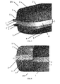
- the cooking vessel 100 illustrated in FIG. figure 1 comprises a first cooking plate 1 and a second cooking plate 2 connected to the first plate 1 by means of a connecting member 3.
- the first and second cooking plates 1,2 each comprise a bottom wall 4, a side wall 5 and an edge 6 defining an annular periphery of the plate 1, 2.
- the side wall 5 extends from the bottom wall 4 to the edge 6.
- a gripping lug 7 extends transversely to the side wall 5 from the edge 6 of each of the plates 1,2.
- each of the first and second cooking plates 1.2 may comprise two gripping lugs 7 on either side of the plate, facilitating the handling of the cooking vessel 100 and the second plate 2, it being specified that only one end is shown on the figure 3 .
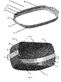
- the joining member 3 is interposed between the first 1 and the second flat 2. As illustrated in FIG. figure 4 it comprises a connecting ring 8 shaped to position overhanging the second plate 2 the first plate 1 and has a generally annular shape (cf. figure 5 ).
- This connecting ring 8 comprises in particular a first low end portion 9 shaped to extend inside the side wall 5 of the first cooking plate 1 and a second high end portion 10 shaped to extend outside the second cooking plate 2.
- a central portion 11 connecting the first and second end portions 9,10 is arranged to be positioned between the edges 6 of the first and second dishes 1,2 cooking.
- the joining member 3 makes it possible to create a socket between the first plate 1 and the second plate 2 and prevents the edge 6 of the second plate 2 from sliding on the edge 6 of the first plate 1 which secures the use of the cooking vessel 100 (cf. figures 4 , 5 and 6 ).
- the junction member 3 also comprises at least one gripping portion 12 extending from the connecting ring 8, transversely from the second high end portion 10 and in the extension of said second high end portion 10 , in the upper part of the ring 8 as shown on the figures 2 , 4 , 5 and 6 .
- This gripping portion 12 has a general shape of shell to cooperate in complementary form with a gripping lug 7 of the second baking dish 2 so that the gripping of the junction member 3 through the gripping portions 12 also carries the second plate 2.
- this shell shape prevents condensation from flowing out of the dishes 1,2.
- Said shell shape is constituted by a rim 13 which defines in its center a housing. In this way, the second plate 2 and the connecting member 3 can be removed together in a single step, which facilitates the use of the cooking vessel 100.
- the gripping portions 12 of the junction member 3 have a suitable size and follow the shape of the gripping ears 7 of the second baking dish 2.
- the gripping portions 12 of the junction member 3 have a larger size than the gripping ears 7 of the second plate 2 without modifying the maintenance of these first and second cooking plates 1,2 and the withdrawal of the second plate 2 together with the joining member 3.
- the removal of the second plate 2 through the junction member 3 is facilitated.
- the connecting member 3 provided with the gripping portions 12 becomes indispensable for lifting the second cooking plate 2 and thus opening the container of cooking 100.
- the gripping portion 12 of the connecting member 3 is shaped to receive a gripping lug 7 of the second flat 2 and further comprises a rim portion 13 which matches the shape of the edge of the gripping lug 7 of the second flat 2.
- the grip of the gripping portion 12 of the junction member 3 takes hold of the gripping lug 7 of the second flat 2.
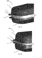
- the gripping portion 12 extends transversely to the second portion of the upper end 10 of the joining member 3 and in the extension thereof (cf. figure 5 ) so that the gripping portion 12 raises the gripping lug 7 of the second flat 2 of the height of the central portion 11.
- This configuration facilitates the handling of the gripping portion 12, in particular as illustrated in FIGS. figures 1 , 3 , 4 , 7A and 7B when the first flat 1 comprises at least one gripping lug 7 arranged opposite that of the second flat 2.
- the junction member 3 may however allow an elevation between the first and second dishes so as to allow the increase of the cooking capacity.
- said raising is obtained by lugs 14 which extend vertically from the central portion 11 (cf. figure 9 and 11 ).
- the present invention proposes a connecting member 3 for holding a second baking dish 2 overhanging a first baking dish 1, and / or for grasping in one operation the second plate 2 and the junction member 3 and / or to increase the cooking capacity of the cooking vessel formed by the first and second dishes 1.2 baking.
Priority Applications (2)
| Application Number | Priority Date | Filing Date | Title |
|---|---|---|---|
| EP13178183.3A EP2829205B1 (de) | 2013-07-26 | 2013-07-26 | Verbindungsorgan zum Verbinden eines ersten Kochtopfs mit einem zweiten Kochtopf |
| ES13178183T ES2745646T3 (es) | 2013-07-26 | 2013-07-26 | Elemento de conexión para conectar un primer plato de cocción y un segundo plato de cocción |
Applications Claiming Priority (1)
| Application Number | Priority Date | Filing Date | Title |
|---|---|---|---|
| EP13178183.3A EP2829205B1 (de) | 2013-07-26 | 2013-07-26 | Verbindungsorgan zum Verbinden eines ersten Kochtopfs mit einem zweiten Kochtopf |
Publications (2)
| Publication Number | Publication Date |
|---|---|
| EP2829205A1 true EP2829205A1 (de) | 2015-01-28 |
| EP2829205B1 EP2829205B1 (de) | 2019-07-03 |
Family
ID=48875580
Family Applications (1)
| Application Number | Title | Priority Date | Filing Date |
|---|---|---|---|
| EP13178183.3A Active EP2829205B1 (de) | 2013-07-26 | 2013-07-26 | Verbindungsorgan zum Verbinden eines ersten Kochtopfs mit einem zweiten Kochtopf |
Country Status (2)
| Country | Link |
|---|---|
| EP (1) | EP2829205B1 (de) |
| ES (1) | ES2745646T3 (de) |
Citations (4)
| Publication number | Priority date | Publication date | Assignee | Title |
|---|---|---|---|---|
| FR1050787A (fr) | 1952-02-13 | 1954-01-11 | Electricite De France | Délimoneur pour canaux d'amenée d'eau |
| FR2719882A1 (fr) * | 1994-05-16 | 1995-11-17 | Kacimi Arezki | Joint d'étanchéité pour ustensile de cuisine pour cuire les aliments à la vapeur. |
| US20030167932A1 (en) * | 2002-03-08 | 2003-09-11 | Chia-Lung Chen | Stackable and configurable colander apparatus |
| FR2955760A1 (fr) * | 2010-02-04 | 2011-08-05 | Herve Meledo | Organe de jonction bord a bord d'un premier et d'un second plat de cuisson |
-
2013
- 2013-07-26 ES ES13178183T patent/ES2745646T3/es active Active
- 2013-07-26 EP EP13178183.3A patent/EP2829205B1/de active Active
Patent Citations (4)
| Publication number | Priority date | Publication date | Assignee | Title |
|---|---|---|---|---|
| FR1050787A (fr) | 1952-02-13 | 1954-01-11 | Electricite De France | Délimoneur pour canaux d'amenée d'eau |
| FR2719882A1 (fr) * | 1994-05-16 | 1995-11-17 | Kacimi Arezki | Joint d'étanchéité pour ustensile de cuisine pour cuire les aliments à la vapeur. |
| US20030167932A1 (en) * | 2002-03-08 | 2003-09-11 | Chia-Lung Chen | Stackable and configurable colander apparatus |
| FR2955760A1 (fr) * | 2010-02-04 | 2011-08-05 | Herve Meledo | Organe de jonction bord a bord d'un premier et d'un second plat de cuisson |
Also Published As
| Publication number | Publication date |
|---|---|
| ES2745646T3 (es) | 2020-03-03 |
| EP2829205B1 (de) | 2019-07-03 |
Similar Documents
| Publication | Publication Date | Title |
|---|---|---|
| EP3398484A1 (de) | Deckel mit regulierbarer dampfauslassöffnung | |
| EP1057437A1 (de) | Multifunktionelles elektrisches Kochgerät | |
| FR2568762A1 (fr) | Recipient pour la cuisson d'aliments et similaires | |
| EP2829205B1 (de) | Verbindungsorgan zum Verbinden eines ersten Kochtopfs mit einem zweiten Kochtopf | |
| EP2536316B1 (de) | Korb für ein elektrisches gerät zum dampfgaren von speisen oder für ein kochutensil | |
| EP2981199B1 (de) | Garvorrichtung und verfahren zum garen eines garguts mit alkohol | |
| EP1941819B1 (de) | Kochgerät | |
| EP3450855A1 (de) | Abdeckelement für eine öffnung eines backhohlraums eines miniofens | |
| EP1154714B1 (de) | Wasserkocher mit heizplatte aus metall | |
| EP3697276B1 (de) | Elektrisches kochgerät mit einem abflussstutzen mit einem deckel | |
| WO2020115245A1 (fr) | Accessoire cuiseur vapeur avec dispositif de support revetu en silicone | |
| EP3890568B1 (de) | Dämpferzubehör mit einer silikonbeschichteten stützvorrichtung | |
| FR3063624B1 (fr) | Dispositif de cuisson en exterieur | |
| EP3886660B1 (de) | Kochanordnung mit einem elektrischen kochgerät und einem ablaufbehälter | |
| EP2353466A1 (de) | Randverbindungselement für eine erste und zweite Kochplatte | |
| WO2005020772A1 (fr) | Recipient de cuisson pour socle chauffant ou socle d'alimentation electrique | |
| EP4265159A1 (de) | Gargerät mit abgasüberwachung | |
| FR3125403A1 (fr) | Dispositif de cuisson sur brûleur à gaz | |
| FR3138862A3 (fr) | Équipement de cuisson de pâtisseries et de desserts sans brûler les mains | |
| WO2021165079A1 (fr) | Moule versatile | |
| WO2021165080A1 (fr) | Moule avec recipients amovibles a prehension facilitee et son support | |
| FR2697425A1 (fr) | Ustensile pour la cuisson de marrons ou analogues. | |
| CH163499A (fr) | Couvercle avec dispositif de refroidissement, pour ustensiles de cuisine. | |
| FR3095934A1 (fr) | récipients à doubles parois | |
| EP3886659A1 (de) | Kochanordnung mit einem elektrischen kochgerät und einem ablaufsockel |
Legal Events
| Date | Code | Title | Description |
|---|---|---|---|
| 17P | Request for examination filed |
Effective date: 20130726 |
|
| AK | Designated contracting states |
Kind code of ref document: A1 Designated state(s): AL AT BE BG CH CY CZ DE DK EE ES FI FR GB GR HR HU IE IS IT LI LT LU LV MC MK MT NL NO PL PT RO RS SE SI SK SM TR |
|
| AX | Request for extension of the european patent |
Extension state: BA ME |
|
| PUAI | Public reference made under article 153(3) epc to a published international application that has entered the european phase |
Free format text: ORIGINAL CODE: 0009012 |
|
| RAP1 | Party data changed (applicant data changed or rights of an application transferred) |
Owner name: MELEDO, HERVE |
|
| RIN1 | Information on inventor provided before grant (corrected) |
Inventor name: MELEDO, HERVE |
|
| R17P | Request for examination filed (corrected) |
Effective date: 20150728 |
|
| RBV | Designated contracting states (corrected) |
Designated state(s): AL AT BE BG CH CY CZ DE DK EE ES FI FR GB GR HR HU IE IS IT LI LT LU LV MC MK MT NL NO PL PT RO RS SE SI SK SM TR |
|
| 17Q | First examination report despatched |
Effective date: 20160929 |
|
| STAA | Information on the status of an ep patent application or granted ep patent |
Free format text: STATUS: EXAMINATION IS IN PROGRESS |
|
| GRAP | Despatch of communication of intention to grant a patent |
Free format text: ORIGINAL CODE: EPIDOSNIGR1 |
|
| STAA | Information on the status of an ep patent application or granted ep patent |
Free format text: STATUS: GRANT OF PATENT IS INTENDED |
|
| INTG | Intention to grant announced |
Effective date: 20190121 |
|
| GRAS | Grant fee paid |
Free format text: ORIGINAL CODE: EPIDOSNIGR3 |
|
| GRAA | (expected) grant |
Free format text: ORIGINAL CODE: 0009210 |
|
| STAA | Information on the status of an ep patent application or granted ep patent |
Free format text: STATUS: THE PATENT HAS BEEN GRANTED |
|
| AK | Designated contracting states |
Kind code of ref document: B1 Designated state(s): AL AT BE BG CH CY CZ DE DK EE ES FI FR GB GR HR HU IE IS IT LI LT LU LV MC MK MT NL NO PL PT RO RS SE SI SK SM TR |
|
| REG | Reference to a national code |
Ref country code: GB Ref legal event code: FG4D Free format text: NOT ENGLISH |
|
| REG | Reference to a national code |
Ref country code: CH Ref legal event code: EP Ref country code: AT Ref legal event code: REF Ref document number: 1149943 Country of ref document: AT Kind code of ref document: T Effective date: 20190715 |
|
| REG | Reference to a national code |
Ref country code: IE Ref legal event code: FG4D Free format text: LANGUAGE OF EP DOCUMENT: FRENCH |
|
| REG | Reference to a national code |
Ref country code: DE Ref legal event code: R096 Ref document number: 602013057318 Country of ref document: DE |
|
| REG | Reference to a national code |
Ref country code: CH Ref legal event code: NV Representative=s name: STOLMAR AND PARTNER INTELLECTUAL PROPERTY S.A., CH |
|
| REG | Reference to a national code |
Ref country code: NL Ref legal event code: MP Effective date: 20190703 |
|
| REG | Reference to a national code |
Ref country code: LT Ref legal event code: MG4D |
|
| REG | Reference to a national code |
Ref country code: AT Ref legal event code: MK05 Ref document number: 1149943 Country of ref document: AT Kind code of ref document: T Effective date: 20190703 |
|
| PG25 | Lapsed in a contracting state [announced via postgrant information from national office to epo] |
Ref country code: CZ Free format text: LAPSE BECAUSE OF FAILURE TO SUBMIT A TRANSLATION OF THE DESCRIPTION OR TO PAY THE FEE WITHIN THE PRESCRIBED TIME-LIMIT Effective date: 20190703 Ref country code: BG Free format text: LAPSE BECAUSE OF FAILURE TO SUBMIT A TRANSLATION OF THE DESCRIPTION OR TO PAY THE FEE WITHIN THE PRESCRIBED TIME-LIMIT Effective date: 20191003 Ref country code: LT Free format text: LAPSE BECAUSE OF FAILURE TO SUBMIT A TRANSLATION OF THE DESCRIPTION OR TO PAY THE FEE WITHIN THE PRESCRIBED TIME-LIMIT Effective date: 20190703 Ref country code: HR Free format text: LAPSE BECAUSE OF FAILURE TO SUBMIT A TRANSLATION OF THE DESCRIPTION OR TO PAY THE FEE WITHIN THE PRESCRIBED TIME-LIMIT Effective date: 20190703 Ref country code: NL Free format text: LAPSE BECAUSE OF FAILURE TO SUBMIT A TRANSLATION OF THE DESCRIPTION OR TO PAY THE FEE WITHIN THE PRESCRIBED TIME-LIMIT Effective date: 20190703 Ref country code: PT Free format text: LAPSE BECAUSE OF FAILURE TO SUBMIT A TRANSLATION OF THE DESCRIPTION OR TO PAY THE FEE WITHIN THE PRESCRIBED TIME-LIMIT Effective date: 20191104 Ref country code: SE Free format text: LAPSE BECAUSE OF FAILURE TO SUBMIT A TRANSLATION OF THE DESCRIPTION OR TO PAY THE FEE WITHIN THE PRESCRIBED TIME-LIMIT Effective date: 20190703 Ref country code: AT Free format text: LAPSE BECAUSE OF FAILURE TO SUBMIT A TRANSLATION OF THE DESCRIPTION OR TO PAY THE FEE WITHIN THE PRESCRIBED TIME-LIMIT Effective date: 20190703 Ref country code: FI Free format text: LAPSE BECAUSE OF FAILURE TO SUBMIT A TRANSLATION OF THE DESCRIPTION OR TO PAY THE FEE WITHIN THE PRESCRIBED TIME-LIMIT Effective date: 20190703 Ref country code: NO Free format text: LAPSE BECAUSE OF FAILURE TO SUBMIT A TRANSLATION OF THE DESCRIPTION OR TO PAY THE FEE WITHIN THE PRESCRIBED TIME-LIMIT Effective date: 20191003 |
|
| PG25 | Lapsed in a contracting state [announced via postgrant information from national office to epo] |
Ref country code: IS Free format text: LAPSE BECAUSE OF FAILURE TO SUBMIT A TRANSLATION OF THE DESCRIPTION OR TO PAY THE FEE WITHIN THE PRESCRIBED TIME-LIMIT Effective date: 20191103 Ref country code: RS Free format text: LAPSE BECAUSE OF FAILURE TO SUBMIT A TRANSLATION OF THE DESCRIPTION OR TO PAY THE FEE WITHIN THE PRESCRIBED TIME-LIMIT Effective date: 20190703 Ref country code: GR Free format text: LAPSE BECAUSE OF FAILURE TO SUBMIT A TRANSLATION OF THE DESCRIPTION OR TO PAY THE FEE WITHIN THE PRESCRIBED TIME-LIMIT Effective date: 20191004 Ref country code: LV Free format text: LAPSE BECAUSE OF FAILURE TO SUBMIT A TRANSLATION OF THE DESCRIPTION OR TO PAY THE FEE WITHIN THE PRESCRIBED TIME-LIMIT Effective date: 20190703 Ref country code: AL Free format text: LAPSE BECAUSE OF FAILURE TO SUBMIT A TRANSLATION OF THE DESCRIPTION OR TO PAY THE FEE WITHIN THE PRESCRIBED TIME-LIMIT Effective date: 20190703 |
|
| REG | Reference to a national code |
Ref country code: ES Ref legal event code: FG2A Ref document number: 2745646 Country of ref document: ES Kind code of ref document: T3 Effective date: 20200303 |
|
| PG25 | Lapsed in a contracting state [announced via postgrant information from national office to epo] |
Ref country code: TR Free format text: LAPSE BECAUSE OF FAILURE TO SUBMIT A TRANSLATION OF THE DESCRIPTION OR TO PAY THE FEE WITHIN THE PRESCRIBED TIME-LIMIT Effective date: 20190703 |
|
| PG25 | Lapsed in a contracting state [announced via postgrant information from national office to epo] |
Ref country code: RO Free format text: LAPSE BECAUSE OF FAILURE TO SUBMIT A TRANSLATION OF THE DESCRIPTION OR TO PAY THE FEE WITHIN THE PRESCRIBED TIME-LIMIT Effective date: 20190703 Ref country code: EE Free format text: LAPSE BECAUSE OF FAILURE TO SUBMIT A TRANSLATION OF THE DESCRIPTION OR TO PAY THE FEE WITHIN THE PRESCRIBED TIME-LIMIT Effective date: 20190703 Ref country code: DK Free format text: LAPSE BECAUSE OF FAILURE TO SUBMIT A TRANSLATION OF THE DESCRIPTION OR TO PAY THE FEE WITHIN THE PRESCRIBED TIME-LIMIT Effective date: 20190703 Ref country code: PL Free format text: LAPSE BECAUSE OF FAILURE TO SUBMIT A TRANSLATION OF THE DESCRIPTION OR TO PAY THE FEE WITHIN THE PRESCRIBED TIME-LIMIT Effective date: 20190703 |
|
| PG25 | Lapsed in a contracting state [announced via postgrant information from national office to epo] |
Ref country code: MC Free format text: LAPSE BECAUSE OF FAILURE TO SUBMIT A TRANSLATION OF THE DESCRIPTION OR TO PAY THE FEE WITHIN THE PRESCRIBED TIME-LIMIT Effective date: 20190703 Ref country code: SK Free format text: LAPSE BECAUSE OF FAILURE TO SUBMIT A TRANSLATION OF THE DESCRIPTION OR TO PAY THE FEE WITHIN THE PRESCRIBED TIME-LIMIT Effective date: 20190703 Ref country code: LU Free format text: LAPSE BECAUSE OF NON-PAYMENT OF DUE FEES Effective date: 20190726 Ref country code: SM Free format text: LAPSE BECAUSE OF FAILURE TO SUBMIT A TRANSLATION OF THE DESCRIPTION OR TO PAY THE FEE WITHIN THE PRESCRIBED TIME-LIMIT Effective date: 20190703 Ref country code: IS Free format text: LAPSE BECAUSE OF FAILURE TO SUBMIT A TRANSLATION OF THE DESCRIPTION OR TO PAY THE FEE WITHIN THE PRESCRIBED TIME-LIMIT Effective date: 20200224 |
|
| REG | Reference to a national code |
Ref country code: DE Ref legal event code: R097 Ref document number: 602013057318 Country of ref document: DE |
|
| PLBE | No opposition filed within time limit |
Free format text: ORIGINAL CODE: 0009261 |
|
| STAA | Information on the status of an ep patent application or granted ep patent |
Free format text: STATUS: NO OPPOSITION FILED WITHIN TIME LIMIT |
|
| PG2D | Information on lapse in contracting state deleted |
Ref country code: IS |
|
| PG25 | Lapsed in a contracting state [announced via postgrant information from national office to epo] |
Ref country code: IE Free format text: LAPSE BECAUSE OF NON-PAYMENT OF DUE FEES Effective date: 20190726 |
|
| 26N | No opposition filed |
Effective date: 20200603 |
|
| PG25 | Lapsed in a contracting state [announced via postgrant information from national office to epo] |
Ref country code: SI Free format text: LAPSE BECAUSE OF FAILURE TO SUBMIT A TRANSLATION OF THE DESCRIPTION OR TO PAY THE FEE WITHIN THE PRESCRIBED TIME-LIMIT Effective date: 20190703 |
|
| PG25 | Lapsed in a contracting state [announced via postgrant information from national office to epo] |
Ref country code: CY Free format text: LAPSE BECAUSE OF FAILURE TO SUBMIT A TRANSLATION OF THE DESCRIPTION OR TO PAY THE FEE WITHIN THE PRESCRIBED TIME-LIMIT Effective date: 20190703 |
|
| PG25 | Lapsed in a contracting state [announced via postgrant information from national office to epo] |
Ref country code: HU Free format text: LAPSE BECAUSE OF FAILURE TO SUBMIT A TRANSLATION OF THE DESCRIPTION OR TO PAY THE FEE WITHIN THE PRESCRIBED TIME-LIMIT; INVALID AB INITIO Effective date: 20130726 Ref country code: MT Free format text: LAPSE BECAUSE OF FAILURE TO SUBMIT A TRANSLATION OF THE DESCRIPTION OR TO PAY THE FEE WITHIN THE PRESCRIBED TIME-LIMIT Effective date: 20190703 |
|
| PG25 | Lapsed in a contracting state [announced via postgrant information from national office to epo] |
Ref country code: MK Free format text: LAPSE BECAUSE OF FAILURE TO SUBMIT A TRANSLATION OF THE DESCRIPTION OR TO PAY THE FEE WITHIN THE PRESCRIBED TIME-LIMIT Effective date: 20190703 |
|
| P01 | Opt-out of the competence of the unified patent court (upc) registered |
Effective date: 20230529 |
|
| PGFP | Annual fee paid to national office [announced via postgrant information from national office to epo] |
Ref country code: IT Payment date: 20230724 Year of fee payment: 11 Ref country code: GB Payment date: 20230720 Year of fee payment: 11 Ref country code: ES Payment date: 20230926 Year of fee payment: 11 Ref country code: CH Payment date: 20230801 Year of fee payment: 11 |
|
| PGFP | Annual fee paid to national office [announced via postgrant information from national office to epo] |
Ref country code: FR Payment date: 20230725 Year of fee payment: 11 Ref country code: DE Payment date: 20230719 Year of fee payment: 11 Ref country code: BE Payment date: 20230719 Year of fee payment: 11 |