EP2828585B1 - Terminal apparatus, e.g. ceiling diffuser of a ventilation system - Google Patents
Terminal apparatus, e.g. ceiling diffuser of a ventilation system Download PDFInfo
- Publication number
- EP2828585B1 EP2828585B1 EP13706565.2A EP13706565A EP2828585B1 EP 2828585 B1 EP2828585 B1 EP 2828585B1 EP 13706565 A EP13706565 A EP 13706565A EP 2828585 B1 EP2828585 B1 EP 2828585B1
- Authority
- EP
- European Patent Office
- Prior art keywords
- terminal apparatus
- actuator
- air
- damper plate
- ceiling diffuser
- Prior art date
- Legal status (The legal status is an assumption and is not a legal conclusion. Google has not performed a legal analysis and makes no representation as to the accuracy of the status listed.)
- Active
Links
Images
Classifications
-
- F—MECHANICAL ENGINEERING; LIGHTING; HEATING; WEAPONS; BLASTING
- F24—HEATING; RANGES; VENTILATING
- F24F—AIR-CONDITIONING; AIR-HUMIDIFICATION; VENTILATION; USE OF AIR CURRENTS FOR SCREENING
- F24F13/00—Details common to, or for air-conditioning, air-humidification, ventilation or use of air currents for screening
- F24F13/02—Ducting arrangements
- F24F13/06—Outlets for directing or distributing air into rooms or spaces, e.g. ceiling air diffuser
-
- F—MECHANICAL ENGINEERING; LIGHTING; HEATING; WEAPONS; BLASTING
- F24—HEATING; RANGES; VENTILATING
- F24F—AIR-CONDITIONING; AIR-HUMIDIFICATION; VENTILATION; USE OF AIR CURRENTS FOR SCREENING
- F24F11/00—Control or safety arrangements
- F24F11/70—Control systems characterised by their outputs; Constructional details thereof
- F24F11/72—Control systems characterised by their outputs; Constructional details thereof for controlling the supply of treated air, e.g. its pressure
- F24F11/74—Control systems characterised by their outputs; Constructional details thereof for controlling the supply of treated air, e.g. its pressure for controlling air flow rate or air velocity
- F24F11/75—Control systems characterised by their outputs; Constructional details thereof for controlling the supply of treated air, e.g. its pressure for controlling air flow rate or air velocity for maintaining constant air flow rate or air velocity
-
- F—MECHANICAL ENGINEERING; LIGHTING; HEATING; WEAPONS; BLASTING
- F24—HEATING; RANGES; VENTILATING
- F24F—AIR-CONDITIONING; AIR-HUMIDIFICATION; VENTILATION; USE OF AIR CURRENTS FOR SCREENING
- F24F11/00—Control or safety arrangements
- F24F11/70—Control systems characterised by their outputs; Constructional details thereof
- F24F11/72—Control systems characterised by their outputs; Constructional details thereof for controlling the supply of treated air, e.g. its pressure
- F24F11/74—Control systems characterised by their outputs; Constructional details thereof for controlling the supply of treated air, e.g. its pressure for controlling air flow rate or air velocity
- F24F11/77—Control systems characterised by their outputs; Constructional details thereof for controlling the supply of treated air, e.g. its pressure for controlling air flow rate or air velocity by controlling the speed of ventilators
-
- F—MECHANICAL ENGINEERING; LIGHTING; HEATING; WEAPONS; BLASTING
- F24—HEATING; RANGES; VENTILATING
- F24F—AIR-CONDITIONING; AIR-HUMIDIFICATION; VENTILATION; USE OF AIR CURRENTS FOR SCREENING
- F24F11/00—Control or safety arrangements
- F24F11/70—Control systems characterised by their outputs; Constructional details thereof
- F24F11/72—Control systems characterised by their outputs; Constructional details thereof for controlling the supply of treated air, e.g. its pressure
- F24F11/79—Control systems characterised by their outputs; Constructional details thereof for controlling the supply of treated air, e.g. its pressure for controlling the direction of the supplied air
-
- F—MECHANICAL ENGINEERING; LIGHTING; HEATING; WEAPONS; BLASTING
- F24—HEATING; RANGES; VENTILATING
- F24F—AIR-CONDITIONING; AIR-HUMIDIFICATION; VENTILATION; USE OF AIR CURRENTS FOR SCREENING
- F24F13/00—Details common to, or for air-conditioning, air-humidification, ventilation or use of air currents for screening
- F24F13/08—Air-flow control members, e.g. louvres, grilles, flaps or guide plates
- F24F13/10—Air-flow control members, e.g. louvres, grilles, flaps or guide plates movable, e.g. dampers
- F24F13/12—Air-flow control members, e.g. louvres, grilles, flaps or guide plates movable, e.g. dampers built up of sliding members
-
- F—MECHANICAL ENGINEERING; LIGHTING; HEATING; WEAPONS; BLASTING
- F24—HEATING; RANGES; VENTILATING
- F24F—AIR-CONDITIONING; AIR-HUMIDIFICATION; VENTILATION; USE OF AIR CURRENTS FOR SCREENING
- F24F13/00—Details common to, or for air-conditioning, air-humidification, ventilation or use of air currents for screening
- F24F13/08—Air-flow control members, e.g. louvres, grilles, flaps or guide plates
- F24F13/10—Air-flow control members, e.g. louvres, grilles, flaps or guide plates movable, e.g. dampers
- F24F13/14—Air-flow control members, e.g. louvres, grilles, flaps or guide plates movable, e.g. dampers built up of tilting members, e.g. louvre
- F24F13/1426—Air-flow control members, e.g. louvres, grilles, flaps or guide plates movable, e.g. dampers built up of tilting members, e.g. louvre characterised by actuating means
- F24F2013/1433—Air-flow control members, e.g. louvres, grilles, flaps or guide plates movable, e.g. dampers built up of tilting members, e.g. louvre characterised by actuating means with electric motors
-
- Y—GENERAL TAGGING OF NEW TECHNOLOGICAL DEVELOPMENTS; GENERAL TAGGING OF CROSS-SECTIONAL TECHNOLOGIES SPANNING OVER SEVERAL SECTIONS OF THE IPC; TECHNICAL SUBJECTS COVERED BY FORMER USPC CROSS-REFERENCE ART COLLECTIONS [XRACs] AND DIGESTS
- Y02—TECHNOLOGIES OR APPLICATIONS FOR MITIGATION OR ADAPTATION AGAINST CLIMATE CHANGE
- Y02B—CLIMATE CHANGE MITIGATION TECHNOLOGIES RELATED TO BUILDINGS, e.g. HOUSING, HOUSE APPLIANCES OR RELATED END-USER APPLICATIONS
- Y02B30/00—Energy efficient heating, ventilation or air conditioning [HVAC]
- Y02B30/70—Efficient control or regulation technologies, e.g. for control of refrigerant flow, motor or heating
Definitions
- the object of this invention is a terminal apparatus of a ventilation duct, via which the incoming air is directed into a room space or corresponding, and in which terminal apparatus the flow aperture leading into the room space is adjustable in height, and for which adjustment the terminal apparatus comprises an actuator, such as an electric motor.
- the invention thus relates to a terminal apparatus of a ventilation system, with which air is supplied into a room space.
- a terminal apparatus in which the invention can be utilized is a so-called ceiling diffuser.
- ceiling diffuser is described, but the invention can also be utilized in other terminal apparatuses for ventilation.
- a ceiling diffuser or other corresponding terminal apparatus by means of it the desired quantity of air is brought into a room space insofar as possible without draughts such that the desired mixing is achieved.
- a ceiling diffuser When supplying air to a room via a ceiling diffuser, one problem that often forms is that the flow length of the airflow depends on the magnitude and temperature of the air current. With small air currents and cold inlet air the throw length is small and correspondingly with large air currents and warm inlet air the throw length is large.
- a solution with the same objective as in this invention i.e. directing air into a room space without draughts is known, e.g. according SE patent 520294 (Lindinvent AB).
- the air current coming from the ceiling diffuser is regulated according to this publication by means of different measured parameters, such as a pressure measurement.
- a drawback in this solution is the dependency on other system components and on the information obtained from them.
- an airflow velocity sensor is used as a sensor, which is installed in the ceiling diffuser in the flow aperture of the air current or in its immediate proximity.
- the velocity sensor, the regulator and the motor controller are integrated into a circuit card, which is connected with a conductor to an electric motor, which opens and closes a moving plate, e.g. a separate deflector plate or diffuser plate, of the ceiling diffuser.
- WO 02/077539 A1 discloses a terminal apparatus, i.e. a ceiling diffuser, of a ventilation duct via which terminal apparatus the incoming air is directed into a room space or corresponding, and in which ceiling diffuser the flow aperture leading into the room space is adjustable in height, and for which adjustment the terminal apparatus comprises an actuator.
- the purpose of this invention is to achieve a more versatile and simpler terminal element of a ventilation system than before, with which air can be brought into a room space evenly and without draughts.
- a terminal apparatus according to the invention is disclosed in claim 1.
- One preferred embodiment of the terminal apparatus according to the invention is characterized in that the terminal apparatus comprises a damper plate, to which the actuator is fixed.
- One preferred embodiment of the terminal apparatus according to the invention is characterized in that the terminal apparatus comprises an air deflector, to which the shaft of the actuator is fixed.
- Yet another preferred embodiment of the terminal apparatus according to the invention is characterized in that the damper plate, the actuator and the air deflector form a functional module, which is installed inside the terminal apparatus.
- the actuator can be adjusted according to the selection in such a way that the diffuser maintains a constant throw length or constant air volume, i.e. there are two ways of using the same product.
- the functional module formed by the damper plate, the actuator and the flow shape part can easily be retrofitted into an existing constant volume diffuser.
- the ceiling diffuser is generally round or rectangular in shape, e.g. of a square shape. Other shapes are also possible within the scope of the invention.
- the body 1 of the ceiling diffuser is installed as an extension of the air duct 2 through an aperture made in the ceiling 2 in a manner that is in itself prior art.
- the trap through which the shaft 4 is taken is marked with the reference number 3.
- a damper plate 5 is connected to the shaft 4, to which damper plate an actuator 6, e.g. an electric motor, is fixed.
- the lowermost is the front plate 7 of the ceiling diffuser, which front plate is suspended on the body 1 of the ceiling diffuser with suspension means 8 ( Fig. 2 ).
- the air deflector is marked with the reference number 9.
- the flow aperture of the ceiling diffuser forms between the air deflector 9 and the damper plate 5.
- the flow aperture adjusts in such a way that the actuator rotates the damper plate, which thus moves upwards or downwards in a threaded spindle 4.
- the actuator 6 is thus fixed to the damper plate 5.
- the shaft 4 of the actuator is in turn fixed to the air deflector 9, in which case these together form a functional module, which is installed inside the ceiling diffuser.
- the module can also easily be retrofitted into an existing constant volume diffuser.
- a pressure difference sensor and control loop are integrated into the actuator 6.
- the actuator can be adjusted according to the selection in such a way that the ceiling diffuser maintains a constant throw length or constant air volume.
- the desired function can be selected from a selector or a switch (not presented) that is in connection with the actuator.
- the apparatus detects by means of the pressure difference sensor an increase in the pressure of the ducting, in which case the damper plate 5 opens, trying to keep the velocity of the air in the gap of the damper plate constant.
- the velocity of the air remains constant, also the throw length remains essentially constant.
- the damper plate is closed.
- the function wherein it is endeavored to maintain a constant air volume is based on the fact that when the pressure of the ducting increases the damper plate is closed and when the pressure decreases the damper plate is opened.
Landscapes
- Engineering & Computer Science (AREA)
- Chemical & Material Sciences (AREA)
- Combustion & Propulsion (AREA)
- Mechanical Engineering (AREA)
- General Engineering & Computer Science (AREA)
- Physics & Mathematics (AREA)
- Fluid Mechanics (AREA)
- Duct Arrangements (AREA)
- Air-Flow Control Members (AREA)
Description
- The object of this invention is a terminal apparatus of a ventilation duct, via which the incoming air is directed into a room space or corresponding, and in which terminal apparatus the flow aperture leading into the room space is adjustable in height, and for which adjustment the terminal apparatus comprises an actuator, such as an electric motor.
- The invention thus relates to a terminal apparatus of a ventilation system, with which air is supplied into a room space. One example of a terminal apparatus in which the invention can be utilized is a so-called ceiling diffuser. Thus in the following a ceiling diffuser is described, but the invention can also be utilized in other terminal apparatuses for ventilation.
- The purpose of a ceiling diffuser or other corresponding terminal apparatus is that by means of it the desired quantity of air is brought into a room space insofar as possible without draughts such that the desired mixing is achieved. When supplying air to a room via a ceiling diffuser, one problem that often forms is that the flow length of the airflow depends on the magnitude and temperature of the air current. With small air currents and cold inlet air the throw length is small and correspondingly with large air currents and warm inlet air the throw length is large.
- It is necessary to permanently place the air deflectors of diffusers in a manner such that in different operating modes sufficiently good mixing of the air is achieved in the room without however causing a feeling that there is a draught. Systems in which the quantity of the air current is controlled according to use, e.g. according to room temperature or CO2 content, might be particularly problematic.
- A solution with the same objective as in this invention, i.e. directing air into a room space without draughts is known, e.g. according
SE patent 520294 - It has been endeavored to solve these problems with a ceiling diffuser according to Finnish patent application 20085187. In it an airflow velocity sensor is used as a sensor, which is installed in the ceiling diffuser in the flow aperture of the air current or in its immediate proximity. In a preferred embodiment the velocity sensor, the regulator and the motor controller are integrated into a circuit card, which is connected with a conductor to an electric motor, which opens and closes a moving plate, e.g. a separate deflector plate or diffuser plate, of the ceiling diffuser.
-
WO 02/077539 A1 - The purpose of this invention is to achieve a more versatile and simpler terminal element of a ventilation system than before, with which air can be brought into a room space evenly and without draughts. A terminal apparatus according to the invention is disclosed in claim 1.
- One preferred embodiment of the terminal apparatus according to the invention is characterized in that the terminal apparatus comprises a damper plate, to which the actuator is fixed.
- One preferred embodiment of the terminal apparatus according to the invention is characterized in that the terminal apparatus comprises an air deflector, to which the shaft of the actuator is fixed.
- Yet another preferred embodiment of the terminal apparatus according to the invention is characterized in that the damper plate, the actuator and the air deflector form a functional module, which is installed inside the terminal apparatus.
- One of the advantages of the invention that can be mentioned is that a separate sensor is no longer needed for giving a signal. The actuator can be adjusted according to the selection in such a way that the diffuser maintains a constant throw length or constant air volume, i.e. there are two ways of using the same product. The functional module formed by the damper plate, the actuator and the flow shape part can easily be retrofitted into an existing constant volume diffuser.
- In the following, the invention will be described in more detail by the aid of some preferred embodiments with reference to the attached drawings, wherein
-
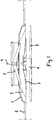
Fig. 1 presents a partially sectioned side view of a ceiling diffuser according to the invention, when installed into position. -
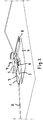
Fig. 2 presents a partially sectioned ceiling diffuser when installed into position, as viewed obliquely from below. - Although the focus here is on a ceiling diffuser, any other terminal apparatus whatsoever of a ventilation system, via which apparatus the airflow is directed into a room space or corresponding, can be relevant. The ceiling diffuser is generally round or rectangular in shape, e.g. of a square shape. Other shapes are also possible within the scope of the invention.
- The body 1 of the ceiling diffuser is installed as an extension of the
air duct 2 through an aperture made in theceiling 2 in a manner that is in itself prior art. The trap through which theshaft 4 is taken is marked with thereference number 3. Adamper plate 5 is connected to theshaft 4, to which damper plate anactuator 6, e.g. an electric motor, is fixed. InFig. 1 the lowermost is thefront plate 7 of the ceiling diffuser, which front plate is suspended on the body 1 of the ceiling diffuser with suspension means 8 (Fig. 2 ). In addition, the air deflector is marked with the reference number 9. - The flow aperture of the ceiling diffuser forms between the air deflector 9 and the
damper plate 5. The flow aperture adjusts in such a way that the actuator rotates the damper plate, which thus moves upwards or downwards in a threadedspindle 4. - The
actuator 6 is thus fixed to thedamper plate 5. Theshaft 4 of the actuator is in turn fixed to the air deflector 9, in which case these together form a functional module, which is installed inside the ceiling diffuser. The module can also easily be retrofitted into an existing constant volume diffuser. - A pressure difference sensor and control loop are integrated into the
actuator 6. The actuator can be adjusted according to the selection in such a way that the ceiling diffuser maintains a constant throw length or constant air volume. The desired function can be selected from a selector or a switch (not presented) that is in connection with the actuator. - When it is desired to maintain a constant throw length, the apparatus detects by means of the pressure difference sensor an increase in the pressure of the ducting, in which case the
damper plate 5 opens, trying to keep the velocity of the air in the gap of the damper plate constant. When the velocity of the air remains constant, also the throw length remains essentially constant. Correspondingly, when the velocity of the air decreases, the damper plate is closed. - The function wherein it is endeavored to maintain a constant air volume is based on the fact that when the pressure of the ducting increases the damper plate is closed and when the pressure decreases the damper plate is opened.
- It is obvious to the person skilled in the art that the invention is not limited to the embodiments presented above, but that it can be varied within the scope of the claims presented below.
- The characteristic features possibly presented in the description in conjunction with other characteristic features can if necessary be used separately to each other.
Claims (5)
- Terminal apparatus of a ventilation duct via which terminal apparatus the incoming air is directed into a room space, and in which terminal apparatus the flow aperture leading into the room space is adjustable in height, and for which adjustment the terminal apparatus comprises an actuator (6), such as an electric motor, characterized in that two alternative functions are integrated into the terminal apparatus, in the first function of which the terminal apparatus maintains a constant throw length, and in the second function a constant air volume, in that these functions can be selected with a switch connected to the actuator, and in that a pressure difference sensor and control loop are integrated into the actuator (6).
- Terminal apparatus according to claim 1, characterized in that the terminal apparatus comprises a damper plate (5) for adjusting the flow aperture, to which damper plate the actuator (6) is fixed.
- Terminal apparatus according to claim 1 or 2, characterized in that the terminal apparatus comprises a shaft (4) and an air deflector (9), to which air deflector the shaft (4) of the actuator (6) is fixed.
- Terminal apparatus according to claim 3, characterized in that the damper plate (5), the actuator (6) and the air deflector (9) form a functional module, which is installed inside the terminal apparatus.
- Terminal apparatus according to any of claims 1-3, characterized in that the terminal apparatus is a ceiling diffuser.
Applications Claiming Priority (2)
| Application Number | Priority Date | Filing Date | Title |
|---|---|---|---|
| FI20125330A FI125065B (en) | 2012-03-23 | 2012-03-23 | Ventilation system terminal, eg ceiling diffuser |
| PCT/EP2013/054133 WO2013139572A1 (en) | 2012-03-23 | 2013-03-01 | Terminal apparatus,e.g. ceiling diffuser, of a ventilation system |
Publications (2)
| Publication Number | Publication Date |
|---|---|
| EP2828585A1 EP2828585A1 (en) | 2015-01-28 |
| EP2828585B1 true EP2828585B1 (en) | 2018-10-10 |
Family
ID=47754553
Family Applications (1)
| Application Number | Title | Priority Date | Filing Date |
|---|---|---|---|
| EP13706565.2A Active EP2828585B1 (en) | 2012-03-23 | 2013-03-01 | Terminal apparatus, e.g. ceiling diffuser of a ventilation system |
Country Status (4)
| Country | Link |
|---|---|
| EP (1) | EP2828585B1 (en) |
| DK (1) | DK2828585T3 (en) |
| FI (1) | FI125065B (en) |
| WO (1) | WO2013139572A1 (en) |
Families Citing this family (5)
| Publication number | Priority date | Publication date | Assignee | Title |
|---|---|---|---|---|
| GB2539625B (en) * | 2015-04-08 | 2020-03-11 | Nuaire Ltd | An air supply and extract vent |
| DE102015107645A1 (en) * | 2015-05-15 | 2016-11-17 | Hella Kgaa Hueck & Co. | Sensor housing for a radar detector and radar sensor |
| AT517276B1 (en) * | 2015-06-05 | 2017-08-15 | Limot Elektromotorenbaugesellschaft M B H & Co Kg | Device for ventilating rooms |
| NO345103B1 (en) * | 2018-10-31 | 2020-09-28 | Trox Auranor Norge As | Cooling baffle |
| CN111292507A (en) * | 2020-03-11 | 2020-06-16 | 徐州柚创谷智能科技有限公司 | Combustible gas early warning device based on Internet of things |
Family Cites Families (6)
| Publication number | Priority date | Publication date | Assignee | Title |
|---|---|---|---|---|
| JP2993412B2 (en) * | 1995-11-20 | 1999-12-20 | 三菱電機株式会社 | Air outlet and air conditioner provided with the air outlet |
| SE520294C2 (en) | 2000-11-14 | 2003-06-24 | Lindinvent Ab | Valve for variable flows, used in ventilation and cooling systems in buildings and houses, has combined fire damper and valve for variable flows |
| EP1370810B1 (en) * | 2001-03-20 | 2006-07-26 | AERMEC S.p.A. | Air-distribution cap for a convector |
| US6736326B2 (en) * | 2002-02-01 | 2004-05-18 | Acutherm L.P. | Thermally powered VAV diffuser and control assembly |
| US6725976B2 (en) * | 2002-03-20 | 2004-04-27 | Invensys Building Systems Inc. | Manual override and locking mechanism and actuator including same |
| US7641125B2 (en) * | 2005-04-29 | 2010-01-05 | E.H. Price Ltd. | Variable air volume ceiling diffuser |
-
2012
- 2012-03-23 FI FI20125330A patent/FI125065B/en active IP Right Grant
-
2013
- 2013-03-01 WO PCT/EP2013/054133 patent/WO2013139572A1/en active Application Filing
- 2013-03-01 EP EP13706565.2A patent/EP2828585B1/en active Active
- 2013-03-01 DK DK13706565.2T patent/DK2828585T3/en active
Non-Patent Citations (1)
| Title |
|---|
| None * |
Also Published As
| Publication number | Publication date |
|---|---|
| WO2013139572A1 (en) | 2013-09-26 |
| DK2828585T3 (en) | 2019-01-28 |
| FI125065B (en) | 2015-05-15 |
| EP2828585A1 (en) | 2015-01-28 |
| FI20125330A (en) | 2013-09-24 |
Similar Documents
| Publication | Publication Date | Title |
|---|---|---|
| EP2828585B1 (en) | Terminal apparatus, e.g. ceiling diffuser of a ventilation system | |
| US7178545B2 (en) | Modulating bypass control system and method | |
| US11680720B2 (en) | Personal comfort variable air volume diffuser | |
| US10337760B2 (en) | Air diffuser and an air circulation system | |
| CN104697058A (en) | Indoor unit of air conditioner and control method of indoor unit | |
| US20120190293A1 (en) | air diffuser and an air circulation system | |
| EP1620681A2 (en) | Method and apparatus for delivering conditioned air using pulse modulation | |
| CN103375882A (en) | Controller circuit for air conditioner and computer-readable storage medium containing program instructions for controlling air conditioner | |
| EP2096366B1 (en) | Terminal apparatus, e.g. ceiling diffuser, of a ventilation system | |
| CN103375849A (en) | Air conditioner | |
| CN113654228A (en) | Air guide structure, air conditioner and control method of air conditioner | |
| EP3018426B1 (en) | Supply and exhaust air terminal device | |
| JP6292987B2 (en) | Air conditioning system | |
| CN110871657A (en) | Non-wind-sensing air supply system of automobile air conditioner and control method of air supply system | |
| JP4401323B2 (en) | Air conditioning control system | |
| EP1918656A2 (en) | Ventilation system | |
| JP6818295B2 (en) | Air conditioning system | |
| CA2797196C (en) | An air diffuser and an air circulation system | |
| CN117212889A (en) | Air duct assembly, air conditioner and air outlet control method | |
| KR101455569B1 (en) | Diffuser | |
| JP2009286270A (en) | Air conditioning system and register for air conditioning | |
| KR100645156B1 (en) | Air vent device having diffuser type | |
| JP2018087671A (en) | Coanda airflow air conditioning system | |
| SE531221C2 (en) | Ventilation system in a multi-dwelling house including pressure switch and adjusting damper in duct duct / ducts | |
| JP2006069364A (en) | Air conditioner for vehicle |
Legal Events
| Date | Code | Title | Description |
|---|---|---|---|
| PUAI | Public reference made under article 153(3) epc to a published international application that has entered the european phase |
Free format text: ORIGINAL CODE: 0009012 |
|
| 17P | Request for examination filed |
Effective date: 20140904 |
|
| AK | Designated contracting states |
Kind code of ref document: A1 Designated state(s): AL AT BE BG CH CY CZ DE DK EE ES FI FR GB GR HR HU IE IS IT LI LT LU LV MC MK MT NL NO PL PT RO RS SE SI SK SM TR |
|
| AX | Request for extension of the european patent |
Extension state: BA ME |
|
| DAX | Request for extension of the european patent (deleted) | ||
| 17Q | First examination report despatched |
Effective date: 20151211 |
|
| STAA | Information on the status of an ep patent application or granted ep patent |
Free format text: STATUS: EXAMINATION IS IN PROGRESS |
|
| GRAJ | Information related to disapproval of communication of intention to grant by the applicant or resumption of examination proceedings by the epo deleted |
Free format text: ORIGINAL CODE: EPIDOSDIGR1 |
|
| GRAP | Despatch of communication of intention to grant a patent |
Free format text: ORIGINAL CODE: EPIDOSNIGR1 |
|
| GRAP | Despatch of communication of intention to grant a patent |
Free format text: ORIGINAL CODE: EPIDOSNIGR1 |
|
| STAA | Information on the status of an ep patent application or granted ep patent |
Free format text: STATUS: GRANT OF PATENT IS INTENDED |
|
| GRAJ | Information related to disapproval of communication of intention to grant by the applicant or resumption of examination proceedings by the epo deleted |
Free format text: ORIGINAL CODE: EPIDOSDIGR1 |
|
| GRAP | Despatch of communication of intention to grant a patent |
Free format text: ORIGINAL CODE: EPIDOSNIGR1 |
|
| GRAS | Grant fee paid |
Free format text: ORIGINAL CODE: EPIDOSNIGR3 |
|
| INTG | Intention to grant announced |
Effective date: 20180126 |
|
| INTC | Intention to grant announced (deleted) | ||
| INTG | Intention to grant announced |
Effective date: 20180214 |
|
| INTG | Intention to grant announced |
Effective date: 20180126 |
|
| RAP1 | Party data changed (applicant data changed or rights of an application transferred) |
Owner name: FLAEKTGROUP SWEDEN AB |
|
| GRAA | (expected) grant |
Free format text: ORIGINAL CODE: 0009210 |
|
| STAA | Information on the status of an ep patent application or granted ep patent |
Free format text: STATUS: THE PATENT HAS BEEN GRANTED |
|
| AK | Designated contracting states |
Kind code of ref document: B1 Designated state(s): AL AT BE BG CH CY CZ DE DK EE ES FI FR GB GR HR HU IE IS IT LI LT LU LV MC MK MT NL NO PL PT RO RS SE SI SK SM TR |
|
| REG | Reference to a national code |
Ref country code: GB Ref legal event code: FG4D |
|
| REG | Reference to a national code |
Ref country code: CH Ref legal event code: EP Ref country code: AT Ref legal event code: REF Ref document number: 1051697 Country of ref document: AT Kind code of ref document: T Effective date: 20181015 |
|
| REG | Reference to a national code |
Ref country code: IE Ref legal event code: FG4D |
|
| REG | Reference to a national code |
Ref country code: DE Ref legal event code: R096 Ref document number: 602013044804 Country of ref document: DE |
|
| REG | Reference to a national code |
Ref country code: SE Ref legal event code: TRGR |
|
| REG | Reference to a national code |
Ref country code: NO Ref legal event code: T2 Effective date: 20181010 |
|
| REG | Reference to a national code |
Ref country code: DK Ref legal event code: T3 Effective date: 20190123 |
|
| REG | Reference to a national code |
Ref country code: NL Ref legal event code: MP Effective date: 20181010 |
|
| REG | Reference to a national code |
Ref country code: LT Ref legal event code: MG4D |
|
| REG | Reference to a national code |
Ref country code: AT Ref legal event code: MK05 Ref document number: 1051697 Country of ref document: AT Kind code of ref document: T Effective date: 20181010 |
|
| PG25 | Lapsed in a contracting state [announced via postgrant information from national office to epo] |
Ref country code: NL Free format text: LAPSE BECAUSE OF FAILURE TO SUBMIT A TRANSLATION OF THE DESCRIPTION OR TO PAY THE FEE WITHIN THE PRESCRIBED TIME-LIMIT Effective date: 20181010 |
|
| PG25 | Lapsed in a contracting state [announced via postgrant information from national office to epo] |
Ref country code: PL Free format text: LAPSE BECAUSE OF FAILURE TO SUBMIT A TRANSLATION OF THE DESCRIPTION OR TO PAY THE FEE WITHIN THE PRESCRIBED TIME-LIMIT Effective date: 20181010 Ref country code: LT Free format text: LAPSE BECAUSE OF FAILURE TO SUBMIT A TRANSLATION OF THE DESCRIPTION OR TO PAY THE FEE WITHIN THE PRESCRIBED TIME-LIMIT Effective date: 20181010 Ref country code: IS Free format text: LAPSE BECAUSE OF FAILURE TO SUBMIT A TRANSLATION OF THE DESCRIPTION OR TO PAY THE FEE WITHIN THE PRESCRIBED TIME-LIMIT Effective date: 20190210 Ref country code: AT Free format text: LAPSE BECAUSE OF FAILURE TO SUBMIT A TRANSLATION OF THE DESCRIPTION OR TO PAY THE FEE WITHIN THE PRESCRIBED TIME-LIMIT Effective date: 20181010 Ref country code: FI Free format text: LAPSE BECAUSE OF FAILURE TO SUBMIT A TRANSLATION OF THE DESCRIPTION OR TO PAY THE FEE WITHIN THE PRESCRIBED TIME-LIMIT Effective date: 20181010 Ref country code: ES Free format text: LAPSE BECAUSE OF FAILURE TO SUBMIT A TRANSLATION OF THE DESCRIPTION OR TO PAY THE FEE WITHIN THE PRESCRIBED TIME-LIMIT Effective date: 20181010 Ref country code: BG Free format text: LAPSE BECAUSE OF FAILURE TO SUBMIT A TRANSLATION OF THE DESCRIPTION OR TO PAY THE FEE WITHIN THE PRESCRIBED TIME-LIMIT Effective date: 20190110 Ref country code: LV Free format text: LAPSE BECAUSE OF FAILURE TO SUBMIT A TRANSLATION OF THE DESCRIPTION OR TO PAY THE FEE WITHIN THE PRESCRIBED TIME-LIMIT Effective date: 20181010 Ref country code: HR Free format text: LAPSE BECAUSE OF FAILURE TO SUBMIT A TRANSLATION OF THE DESCRIPTION OR TO PAY THE FEE WITHIN THE PRESCRIBED TIME-LIMIT Effective date: 20181010 |
|
| PG25 | Lapsed in a contracting state [announced via postgrant information from national office to epo] |
Ref country code: AL Free format text: LAPSE BECAUSE OF FAILURE TO SUBMIT A TRANSLATION OF THE DESCRIPTION OR TO PAY THE FEE WITHIN THE PRESCRIBED TIME-LIMIT Effective date: 20181010 Ref country code: PT Free format text: LAPSE BECAUSE OF FAILURE TO SUBMIT A TRANSLATION OF THE DESCRIPTION OR TO PAY THE FEE WITHIN THE PRESCRIBED TIME-LIMIT Effective date: 20190210 Ref country code: RS Free format text: LAPSE BECAUSE OF FAILURE TO SUBMIT A TRANSLATION OF THE DESCRIPTION OR TO PAY THE FEE WITHIN THE PRESCRIBED TIME-LIMIT Effective date: 20181010 Ref country code: GR Free format text: LAPSE BECAUSE OF FAILURE TO SUBMIT A TRANSLATION OF THE DESCRIPTION OR TO PAY THE FEE WITHIN THE PRESCRIBED TIME-LIMIT Effective date: 20190111 |
|
| REG | Reference to a national code |
Ref country code: DE Ref legal event code: R097 Ref document number: 602013044804 Country of ref document: DE |
|
| PG25 | Lapsed in a contracting state [announced via postgrant information from national office to epo] |
Ref country code: CZ Free format text: LAPSE BECAUSE OF FAILURE TO SUBMIT A TRANSLATION OF THE DESCRIPTION OR TO PAY THE FEE WITHIN THE PRESCRIBED TIME-LIMIT Effective date: 20181010 Ref country code: IT Free format text: LAPSE BECAUSE OF FAILURE TO SUBMIT A TRANSLATION OF THE DESCRIPTION OR TO PAY THE FEE WITHIN THE PRESCRIBED TIME-LIMIT Effective date: 20181010 |
|
| PLBE | No opposition filed within time limit |
Free format text: ORIGINAL CODE: 0009261 |
|
| STAA | Information on the status of an ep patent application or granted ep patent |
Free format text: STATUS: NO OPPOSITION FILED WITHIN TIME LIMIT |
|
| PG25 | Lapsed in a contracting state [announced via postgrant information from national office to epo] |
Ref country code: RO Free format text: LAPSE BECAUSE OF FAILURE TO SUBMIT A TRANSLATION OF THE DESCRIPTION OR TO PAY THE FEE WITHIN THE PRESCRIBED TIME-LIMIT Effective date: 20181010 Ref country code: EE Free format text: LAPSE BECAUSE OF FAILURE TO SUBMIT A TRANSLATION OF THE DESCRIPTION OR TO PAY THE FEE WITHIN THE PRESCRIBED TIME-LIMIT Effective date: 20181010 Ref country code: SM Free format text: LAPSE BECAUSE OF FAILURE TO SUBMIT A TRANSLATION OF THE DESCRIPTION OR TO PAY THE FEE WITHIN THE PRESCRIBED TIME-LIMIT Effective date: 20181010 Ref country code: SK Free format text: LAPSE BECAUSE OF FAILURE TO SUBMIT A TRANSLATION OF THE DESCRIPTION OR TO PAY THE FEE WITHIN THE PRESCRIBED TIME-LIMIT Effective date: 20181010 |
|
| 26N | No opposition filed |
Effective date: 20190711 |
|
| PG25 | Lapsed in a contracting state [announced via postgrant information from national office to epo] |
Ref country code: MC Free format text: LAPSE BECAUSE OF FAILURE TO SUBMIT A TRANSLATION OF THE DESCRIPTION OR TO PAY THE FEE WITHIN THE PRESCRIBED TIME-LIMIT Effective date: 20181010 Ref country code: SI Free format text: LAPSE BECAUSE OF FAILURE TO SUBMIT A TRANSLATION OF THE DESCRIPTION OR TO PAY THE FEE WITHIN THE PRESCRIBED TIME-LIMIT Effective date: 20181010 |
|
| REG | Reference to a national code |
Ref country code: CH Ref legal event code: PL |
|
| PG25 | Lapsed in a contracting state [announced via postgrant information from national office to epo] |
Ref country code: LU Free format text: LAPSE BECAUSE OF NON-PAYMENT OF DUE FEES Effective date: 20190301 |
|
| REG | Reference to a national code |
Ref country code: BE Ref legal event code: MM Effective date: 20190331 |
|
| PG25 | Lapsed in a contracting state [announced via postgrant information from national office to epo] |
Ref country code: CH Free format text: LAPSE BECAUSE OF NON-PAYMENT OF DUE FEES Effective date: 20190331 Ref country code: LI Free format text: LAPSE BECAUSE OF NON-PAYMENT OF DUE FEES Effective date: 20190331 Ref country code: IE Free format text: LAPSE BECAUSE OF NON-PAYMENT OF DUE FEES Effective date: 20190301 |
|
| PG25 | Lapsed in a contracting state [announced via postgrant information from national office to epo] |
Ref country code: BE Free format text: LAPSE BECAUSE OF NON-PAYMENT OF DUE FEES Effective date: 20190331 |
|
| PG25 | Lapsed in a contracting state [announced via postgrant information from national office to epo] |
Ref country code: TR Free format text: LAPSE BECAUSE OF FAILURE TO SUBMIT A TRANSLATION OF THE DESCRIPTION OR TO PAY THE FEE WITHIN THE PRESCRIBED TIME-LIMIT Effective date: 20181010 |
|
| PG25 | Lapsed in a contracting state [announced via postgrant information from national office to epo] |
Ref country code: MT Free format text: LAPSE BECAUSE OF NON-PAYMENT OF DUE FEES Effective date: 20190301 |
|
| PG25 | Lapsed in a contracting state [announced via postgrant information from national office to epo] |
Ref country code: CY Free format text: LAPSE BECAUSE OF FAILURE TO SUBMIT A TRANSLATION OF THE DESCRIPTION OR TO PAY THE FEE WITHIN THE PRESCRIBED TIME-LIMIT Effective date: 20181010 |
|
| PG25 | Lapsed in a contracting state [announced via postgrant information from national office to epo] |
Ref country code: HU Free format text: LAPSE BECAUSE OF FAILURE TO SUBMIT A TRANSLATION OF THE DESCRIPTION OR TO PAY THE FEE WITHIN THE PRESCRIBED TIME-LIMIT; INVALID AB INITIO Effective date: 20130301 |
|
| PG25 | Lapsed in a contracting state [announced via postgrant information from national office to epo] |
Ref country code: MK Free format text: LAPSE BECAUSE OF FAILURE TO SUBMIT A TRANSLATION OF THE DESCRIPTION OR TO PAY THE FEE WITHIN THE PRESCRIBED TIME-LIMIT Effective date: 20181010 |
|
| REG | Reference to a national code |
Ref country code: DE Ref legal event code: R082 Ref document number: 602013044804 Country of ref document: DE Representative=s name: LEONHARD, REIMUND, DIPL.-ING., DE |
|
| PGFP | Annual fee paid to national office [announced via postgrant information from national office to epo] |
Ref country code: NO Payment date: 20230317 Year of fee payment: 11 Ref country code: FR Payment date: 20230314 Year of fee payment: 11 Ref country code: DK Payment date: 20230316 Year of fee payment: 11 |
|
| PGFP | Annual fee paid to national office [announced via postgrant information from national office to epo] |
Ref country code: SE Payment date: 20230314 Year of fee payment: 11 Ref country code: GB Payment date: 20230317 Year of fee payment: 11 Ref country code: DE Payment date: 20230323 Year of fee payment: 11 |