EP2828585B1 - Endgerätevorrichtung, z. b. deckendiffusor eines belüftungssystems - Google Patents
Endgerätevorrichtung, z. b. deckendiffusor eines belüftungssystems Download PDFInfo
- Publication number
- EP2828585B1 EP2828585B1 EP13706565.2A EP13706565A EP2828585B1 EP 2828585 B1 EP2828585 B1 EP 2828585B1 EP 13706565 A EP13706565 A EP 13706565A EP 2828585 B1 EP2828585 B1 EP 2828585B1
- Authority
- EP
- European Patent Office
- Prior art keywords
- terminal apparatus
- actuator
- air
- damper plate
- ceiling diffuser
- Prior art date
- Legal status (The legal status is an assumption and is not a legal conclusion. Google has not performed a legal analysis and makes no representation as to the accuracy of the status listed.)
- Active
Links
- 238000009423 ventilation Methods 0.000 title claims description 8
- 230000007423 decrease Effects 0.000 description 2
- 238000009530 blood pressure measurement Methods 0.000 description 1
- 239000004020 conductor Substances 0.000 description 1
- 230000001105 regulatory effect Effects 0.000 description 1
- 239000000725 suspension Substances 0.000 description 1
Images
Classifications
-
- F—MECHANICAL ENGINEERING; LIGHTING; HEATING; WEAPONS; BLASTING
- F24—HEATING; RANGES; VENTILATING
- F24F—AIR-CONDITIONING; AIR-HUMIDIFICATION; VENTILATION; USE OF AIR CURRENTS FOR SCREENING
- F24F13/00—Details common to, or for air-conditioning, air-humidification, ventilation or use of air currents for screening
- F24F13/02—Ducting arrangements
- F24F13/06—Outlets for directing or distributing air into rooms or spaces, e.g. ceiling air diffuser
-
- F—MECHANICAL ENGINEERING; LIGHTING; HEATING; WEAPONS; BLASTING
- F24—HEATING; RANGES; VENTILATING
- F24F—AIR-CONDITIONING; AIR-HUMIDIFICATION; VENTILATION; USE OF AIR CURRENTS FOR SCREENING
- F24F11/00—Control or safety arrangements
- F24F11/70—Control systems characterised by their outputs; Constructional details thereof
- F24F11/72—Control systems characterised by their outputs; Constructional details thereof for controlling the supply of treated air, e.g. its pressure
- F24F11/74—Control systems characterised by their outputs; Constructional details thereof for controlling the supply of treated air, e.g. its pressure for controlling air flow rate or air velocity
- F24F11/75—Control systems characterised by their outputs; Constructional details thereof for controlling the supply of treated air, e.g. its pressure for controlling air flow rate or air velocity for maintaining constant air flow rate or air velocity
-
- F—MECHANICAL ENGINEERING; LIGHTING; HEATING; WEAPONS; BLASTING
- F24—HEATING; RANGES; VENTILATING
- F24F—AIR-CONDITIONING; AIR-HUMIDIFICATION; VENTILATION; USE OF AIR CURRENTS FOR SCREENING
- F24F11/00—Control or safety arrangements
- F24F11/70—Control systems characterised by their outputs; Constructional details thereof
- F24F11/72—Control systems characterised by their outputs; Constructional details thereof for controlling the supply of treated air, e.g. its pressure
- F24F11/74—Control systems characterised by their outputs; Constructional details thereof for controlling the supply of treated air, e.g. its pressure for controlling air flow rate or air velocity
- F24F11/77—Control systems characterised by their outputs; Constructional details thereof for controlling the supply of treated air, e.g. its pressure for controlling air flow rate or air velocity by controlling the speed of ventilators
-
- F—MECHANICAL ENGINEERING; LIGHTING; HEATING; WEAPONS; BLASTING
- F24—HEATING; RANGES; VENTILATING
- F24F—AIR-CONDITIONING; AIR-HUMIDIFICATION; VENTILATION; USE OF AIR CURRENTS FOR SCREENING
- F24F11/00—Control or safety arrangements
- F24F11/70—Control systems characterised by their outputs; Constructional details thereof
- F24F11/72—Control systems characterised by their outputs; Constructional details thereof for controlling the supply of treated air, e.g. its pressure
- F24F11/79—Control systems characterised by their outputs; Constructional details thereof for controlling the supply of treated air, e.g. its pressure for controlling the direction of the supplied air
-
- F—MECHANICAL ENGINEERING; LIGHTING; HEATING; WEAPONS; BLASTING
- F24—HEATING; RANGES; VENTILATING
- F24F—AIR-CONDITIONING; AIR-HUMIDIFICATION; VENTILATION; USE OF AIR CURRENTS FOR SCREENING
- F24F13/00—Details common to, or for air-conditioning, air-humidification, ventilation or use of air currents for screening
- F24F13/08—Air-flow control members, e.g. louvres, grilles, flaps or guide plates
- F24F13/10—Air-flow control members, e.g. louvres, grilles, flaps or guide plates movable, e.g. dampers
- F24F13/12—Air-flow control members, e.g. louvres, grilles, flaps or guide plates movable, e.g. dampers built up of sliding members
-
- F—MECHANICAL ENGINEERING; LIGHTING; HEATING; WEAPONS; BLASTING
- F24—HEATING; RANGES; VENTILATING
- F24F—AIR-CONDITIONING; AIR-HUMIDIFICATION; VENTILATION; USE OF AIR CURRENTS FOR SCREENING
- F24F13/00—Details common to, or for air-conditioning, air-humidification, ventilation or use of air currents for screening
- F24F13/08—Air-flow control members, e.g. louvres, grilles, flaps or guide plates
- F24F13/10—Air-flow control members, e.g. louvres, grilles, flaps or guide plates movable, e.g. dampers
- F24F13/14—Air-flow control members, e.g. louvres, grilles, flaps or guide plates movable, e.g. dampers built up of tilting members, e.g. louvre
- F24F13/1426—Air-flow control members, e.g. louvres, grilles, flaps or guide plates movable, e.g. dampers built up of tilting members, e.g. louvre characterised by actuating means
- F24F2013/1433—Air-flow control members, e.g. louvres, grilles, flaps or guide plates movable, e.g. dampers built up of tilting members, e.g. louvre characterised by actuating means with electric motors
-
- Y—GENERAL TAGGING OF NEW TECHNOLOGICAL DEVELOPMENTS; GENERAL TAGGING OF CROSS-SECTIONAL TECHNOLOGIES SPANNING OVER SEVERAL SECTIONS OF THE IPC; TECHNICAL SUBJECTS COVERED BY FORMER USPC CROSS-REFERENCE ART COLLECTIONS [XRACs] AND DIGESTS
- Y02—TECHNOLOGIES OR APPLICATIONS FOR MITIGATION OR ADAPTATION AGAINST CLIMATE CHANGE
- Y02B—CLIMATE CHANGE MITIGATION TECHNOLOGIES RELATED TO BUILDINGS, e.g. HOUSING, HOUSE APPLIANCES OR RELATED END-USER APPLICATIONS
- Y02B30/00—Energy efficient heating, ventilation or air conditioning [HVAC]
- Y02B30/70—Efficient control or regulation technologies, e.g. for control of refrigerant flow, motor or heating
Definitions
- the object of this invention is a terminal apparatus of a ventilation duct, via which the incoming air is directed into a room space or corresponding, and in which terminal apparatus the flow aperture leading into the room space is adjustable in height, and for which adjustment the terminal apparatus comprises an actuator, such as an electric motor.
- the invention thus relates to a terminal apparatus of a ventilation system, with which air is supplied into a room space.
- a terminal apparatus in which the invention can be utilized is a so-called ceiling diffuser.
- ceiling diffuser is described, but the invention can also be utilized in other terminal apparatuses for ventilation.
- a ceiling diffuser or other corresponding terminal apparatus by means of it the desired quantity of air is brought into a room space insofar as possible without draughts such that the desired mixing is achieved.
- a ceiling diffuser When supplying air to a room via a ceiling diffuser, one problem that often forms is that the flow length of the airflow depends on the magnitude and temperature of the air current. With small air currents and cold inlet air the throw length is small and correspondingly with large air currents and warm inlet air the throw length is large.
- a solution with the same objective as in this invention i.e. directing air into a room space without draughts is known, e.g. according SE patent 520294 (Lindinvent AB).
- the air current coming from the ceiling diffuser is regulated according to this publication by means of different measured parameters, such as a pressure measurement.
- a drawback in this solution is the dependency on other system components and on the information obtained from them.
- an airflow velocity sensor is used as a sensor, which is installed in the ceiling diffuser in the flow aperture of the air current or in its immediate proximity.
- the velocity sensor, the regulator and the motor controller are integrated into a circuit card, which is connected with a conductor to an electric motor, which opens and closes a moving plate, e.g. a separate deflector plate or diffuser plate, of the ceiling diffuser.
- WO 02/077539 A1 discloses a terminal apparatus, i.e. a ceiling diffuser, of a ventilation duct via which terminal apparatus the incoming air is directed into a room space or corresponding, and in which ceiling diffuser the flow aperture leading into the room space is adjustable in height, and for which adjustment the terminal apparatus comprises an actuator.
- the purpose of this invention is to achieve a more versatile and simpler terminal element of a ventilation system than before, with which air can be brought into a room space evenly and without draughts.
- a terminal apparatus according to the invention is disclosed in claim 1.
- One preferred embodiment of the terminal apparatus according to the invention is characterized in that the terminal apparatus comprises a damper plate, to which the actuator is fixed.
- One preferred embodiment of the terminal apparatus according to the invention is characterized in that the terminal apparatus comprises an air deflector, to which the shaft of the actuator is fixed.
- Yet another preferred embodiment of the terminal apparatus according to the invention is characterized in that the damper plate, the actuator and the air deflector form a functional module, which is installed inside the terminal apparatus.
- the actuator can be adjusted according to the selection in such a way that the diffuser maintains a constant throw length or constant air volume, i.e. there are two ways of using the same product.
- the functional module formed by the damper plate, the actuator and the flow shape part can easily be retrofitted into an existing constant volume diffuser.
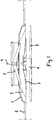
- the ceiling diffuser is generally round or rectangular in shape, e.g. of a square shape. Other shapes are also possible within the scope of the invention.
- the body 1 of the ceiling diffuser is installed as an extension of the air duct 2 through an aperture made in the ceiling 2 in a manner that is in itself prior art.
- the trap through which the shaft 4 is taken is marked with the reference number 3.
- a damper plate 5 is connected to the shaft 4, to which damper plate an actuator 6, e.g. an electric motor, is fixed.
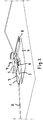
- the lowermost is the front plate 7 of the ceiling diffuser, which front plate is suspended on the body 1 of the ceiling diffuser with suspension means 8 ( Fig. 2 ).
- the air deflector is marked with the reference number 9.
- the flow aperture of the ceiling diffuser forms between the air deflector 9 and the damper plate 5.
- the flow aperture adjusts in such a way that the actuator rotates the damper plate, which thus moves upwards or downwards in a threaded spindle 4.
- the actuator 6 is thus fixed to the damper plate 5.
- the shaft 4 of the actuator is in turn fixed to the air deflector 9, in which case these together form a functional module, which is installed inside the ceiling diffuser.
- the module can also easily be retrofitted into an existing constant volume diffuser.
- a pressure difference sensor and control loop are integrated into the actuator 6.
- the actuator can be adjusted according to the selection in such a way that the ceiling diffuser maintains a constant throw length or constant air volume.
- the desired function can be selected from a selector or a switch (not presented) that is in connection with the actuator.
- the apparatus detects by means of the pressure difference sensor an increase in the pressure of the ducting, in which case the damper plate 5 opens, trying to keep the velocity of the air in the gap of the damper plate constant.
- the velocity of the air remains constant, also the throw length remains essentially constant.
- the damper plate is closed.
- the function wherein it is endeavored to maintain a constant air volume is based on the fact that when the pressure of the ducting increases the damper plate is closed and when the pressure decreases the damper plate is opened.
Landscapes
- Engineering & Computer Science (AREA)
- Chemical & Material Sciences (AREA)
- Combustion & Propulsion (AREA)
- Mechanical Engineering (AREA)
- General Engineering & Computer Science (AREA)
- Physics & Mathematics (AREA)
- Fluid Mechanics (AREA)
- Duct Arrangements (AREA)
- Air-Flow Control Members (AREA)
Claims (5)
- Endvorrichtung eines Lüftungskanals, durch die die ankommende Luft in einen Raum geleitet wird, und wobei die Strömungsöffnung der Endvorrichtung, die in den Raum führt, höhenverstellbar ist, und wobei die Endvorrichtung für das Verstellen einen Stellantrieb (6), z.B. einen Elektromotor, umfasst, dadurch gekennzeichnet, dass zwei alternative Funktionen in der Endvorrichtung integriert sind, wobei die Endvorrichtung innerhalb der ersten Funktion eine konstante Wurflänge beibehält und innerhalb der zweiten Funktion ein konstantes Luftvolumen beibehält, dadurch, dass die Funktionen durch einen Schalter, der mit dem Stellantrieb verbunden ist, auswählbar sind, und dadurch, dass ein Druckdifferenzsensor und ein Regelkreis in dem Stellantrieb (6) integriert sind.
- Endvorrichtung nach Anspruch 1, dadurch gekennzeichnet, dass die Endvorrichtung eine Dämpferplatte (5) zum Verstellen der Strömungsöffnung umfasst, wobei der Stellantrieb (6) an der Dämpferplatte befestigt ist.
- Endvorrichtung nach Anspruch 1 oder 2, dadurch gekennzeichnet, dass die Endvorrichtung eine Welle (4) und eine Luftlenkung (9) umfasst, wobei die Welle (4) des Stellantriebs (6) an der Luftlenkung befestigt ist.
- Endvorrichtung nach Anspruch 3, dadurch gekennzeichnet, dass die Dämpferplatte (5), der Stellantrieb (6) und die Luftlenkung (9) eine funktionelle Baugruppe bilden, die in der Endvorrichtung eingebaut ist.
- Endvorrichtung nach einem der Ansprüche 1 bis 3, dadurch gekennzeichnet, dass die Endvorrichtung ein Deckendiffusor ist.
Applications Claiming Priority (2)
| Application Number | Priority Date | Filing Date | Title |
|---|---|---|---|
| FI20125330A FI125065B (fi) | 2012-03-23 | 2012-03-23 | Ilmanvaihtojärjestelmän päätelaite, esimerkiksi kattohajoitin |
| PCT/EP2013/054133 WO2013139572A1 (en) | 2012-03-23 | 2013-03-01 | Terminal apparatus,e.g. ceiling diffuser, of a ventilation system |
Publications (2)
| Publication Number | Publication Date |
|---|---|
| EP2828585A1 EP2828585A1 (de) | 2015-01-28 |
| EP2828585B1 true EP2828585B1 (de) | 2018-10-10 |
Family
ID=47754553
Family Applications (1)
| Application Number | Title | Priority Date | Filing Date |
|---|---|---|---|
| EP13706565.2A Active EP2828585B1 (de) | 2012-03-23 | 2013-03-01 | Endgerätevorrichtung, z. b. deckendiffusor eines belüftungssystems |
Country Status (4)
| Country | Link |
|---|---|
| EP (1) | EP2828585B1 (de) |
| DK (1) | DK2828585T3 (de) |
| FI (1) | FI125065B (de) |
| WO (1) | WO2013139572A1 (de) |
Families Citing this family (5)
| Publication number | Priority date | Publication date | Assignee | Title |
|---|---|---|---|---|
| GB2539625B (en) * | 2015-04-08 | 2020-03-11 | Nuaire Ltd | An air supply and extract vent |
| DE102015107645A1 (de) * | 2015-05-15 | 2016-11-17 | Hella Kgaa Hueck & Co. | Sensorgehäuse für einen Radardensor und Radarsensor |
| AT517276B1 (de) * | 2015-06-05 | 2017-08-15 | Limot Elektromotorenbaugesellschaft M B H & Co Kg | Vorrichtung zum Lüften von Räumen |
| NO345103B1 (no) * | 2018-10-31 | 2020-09-28 | Trox Auranor Norge As | Kjølebaffel |
| CN111292507A (zh) * | 2020-03-11 | 2020-06-16 | 徐州柚创谷智能科技有限公司 | 基于物联网的可燃气体预警器 |
Family Cites Families (6)
| Publication number | Priority date | Publication date | Assignee | Title |
|---|---|---|---|---|
| JP2993412B2 (ja) * | 1995-11-20 | 1999-12-20 | 三菱電機株式会社 | 吹出口及び該吹出口を備えた空気調和装置 |
| SE520294C2 (sv) | 2000-11-14 | 2003-06-24 | Lindinvent Ab | Ventil för varierbar strypning av flöden |
| YU73103A (sh) * | 2001-03-20 | 2004-09-03 | Aermec S.P.A. | Poklopac za razvod vazduha za konvektor |
| US6736326B2 (en) * | 2002-02-01 | 2004-05-18 | Acutherm L.P. | Thermally powered VAV diffuser and control assembly |
| US6725976B2 (en) * | 2002-03-20 | 2004-04-27 | Invensys Building Systems Inc. | Manual override and locking mechanism and actuator including same |
| US7641125B2 (en) * | 2005-04-29 | 2010-01-05 | E.H. Price Ltd. | Variable air volume ceiling diffuser |
-
2012
- 2012-03-23 FI FI20125330A patent/FI125065B/fi active IP Right Grant
-
2013
- 2013-03-01 DK DK13706565.2T patent/DK2828585T3/en active
- 2013-03-01 EP EP13706565.2A patent/EP2828585B1/de active Active
- 2013-03-01 WO PCT/EP2013/054133 patent/WO2013139572A1/en active Application Filing
Non-Patent Citations (1)
| Title |
|---|
| None * |
Also Published As
| Publication number | Publication date |
|---|---|
| DK2828585T3 (en) | 2019-01-28 |
| FI20125330A (fi) | 2013-09-24 |
| FI125065B (fi) | 2015-05-15 |
| EP2828585A1 (de) | 2015-01-28 |
| WO2013139572A1 (en) | 2013-09-26 |
Similar Documents
| Publication | Publication Date | Title |
|---|---|---|
| EP2828585B1 (de) | Endgerätevorrichtung, z. b. deckendiffusor eines belüftungssystems | |
| US7178545B2 (en) | Modulating bypass control system and method | |
| US11680720B2 (en) | Personal comfort variable air volume diffuser | |
| US10337760B2 (en) | Air diffuser and an air circulation system | |
| CN104697058A (zh) | 空调室内机及其控制方法 | |
| US20120190293A1 (en) | air diffuser and an air circulation system | |
| CN103375882A (zh) | 用于空调器的控制电路以及包含用于控制空调器的程序指令的计算机可读存储介质 | |
| EP2096366B1 (de) | Endgerät, z. B. Deckendiffusor, eines Belüftungssystem | |
| CN113654228B (zh) | 导风结构、空调器及空调器的控制方法 | |
| CN103375849A (zh) | 空调器 | |
| EP3018426B1 (de) | Zuluft- und Abluftendgerätevorrichtung | |
| JP6292987B2 (ja) | 空気調和システム | |
| JP6976779B2 (ja) | 空調システム | |
| CN110871657A (zh) | 汽车空调的无风感送风系统及送风系统的控制方法 | |
| JP4401323B2 (ja) | 空調制御システム | |
| EP1918656A2 (de) | Belüftungssystem | |
| JP6818295B2 (ja) | 空気調和システム | |
| EP1826039A3 (de) | Ventil mit veränderbarem Durchfluss | |
| CA2797196C (en) | An air diffuser and an air circulation system | |
| CN117212889A (zh) | 风道组件、空调器以及出风控制方法 | |
| KR101455569B1 (ko) | 디퓨저 | |
| JP2009286270A (ja) | 空調システム及び空調用レジスタ | |
| KR100645156B1 (ko) | 디퓨저 타입 에어벤트 장치 | |
| JP2018087671A (ja) | コアンダ気流空調システム | |
| SE531221C2 (sv) | Ventilationssystem i ett flerbostadshus innefattande tryckvakt och injusteringsspjäll i imkanal/imkanaler |
Legal Events
| Date | Code | Title | Description |
|---|---|---|---|
| PUAI | Public reference made under article 153(3) epc to a published international application that has entered the european phase |
Free format text: ORIGINAL CODE: 0009012 |
|
| 17P | Request for examination filed |
Effective date: 20140904 |
|
| AK | Designated contracting states |
Kind code of ref document: A1 Designated state(s): AL AT BE BG CH CY CZ DE DK EE ES FI FR GB GR HR HU IE IS IT LI LT LU LV MC MK MT NL NO PL PT RO RS SE SI SK SM TR |
|
| AX | Request for extension of the european patent |
Extension state: BA ME |
|
| DAX | Request for extension of the european patent (deleted) | ||
| 17Q | First examination report despatched |
Effective date: 20151211 |
|
| STAA | Information on the status of an ep patent application or granted ep patent |
Free format text: STATUS: EXAMINATION IS IN PROGRESS |
|
| GRAJ | Information related to disapproval of communication of intention to grant by the applicant or resumption of examination proceedings by the epo deleted |
Free format text: ORIGINAL CODE: EPIDOSDIGR1 |
|
| GRAP | Despatch of communication of intention to grant a patent |
Free format text: ORIGINAL CODE: EPIDOSNIGR1 |
|
| GRAP | Despatch of communication of intention to grant a patent |
Free format text: ORIGINAL CODE: EPIDOSNIGR1 |
|
| STAA | Information on the status of an ep patent application or granted ep patent |
Free format text: STATUS: GRANT OF PATENT IS INTENDED |
|
| GRAJ | Information related to disapproval of communication of intention to grant by the applicant or resumption of examination proceedings by the epo deleted |
Free format text: ORIGINAL CODE: EPIDOSDIGR1 |
|
| GRAP | Despatch of communication of intention to grant a patent |
Free format text: ORIGINAL CODE: EPIDOSNIGR1 |
|
| GRAS | Grant fee paid |
Free format text: ORIGINAL CODE: EPIDOSNIGR3 |
|
| INTG | Intention to grant announced |
Effective date: 20180126 |
|
| INTC | Intention to grant announced (deleted) | ||
| INTG | Intention to grant announced |
Effective date: 20180214 |
|
| INTG | Intention to grant announced |
Effective date: 20180126 |
|
| RAP1 | Party data changed (applicant data changed or rights of an application transferred) |
Owner name: FLAEKTGROUP SWEDEN AB |
|
| GRAA | (expected) grant |
Free format text: ORIGINAL CODE: 0009210 |
|
| STAA | Information on the status of an ep patent application or granted ep patent |
Free format text: STATUS: THE PATENT HAS BEEN GRANTED |
|
| AK | Designated contracting states |
Kind code of ref document: B1 Designated state(s): AL AT BE BG CH CY CZ DE DK EE ES FI FR GB GR HR HU IE IS IT LI LT LU LV MC MK MT NL NO PL PT RO RS SE SI SK SM TR |
|
| REG | Reference to a national code |
Ref country code: GB Ref legal event code: FG4D |
|
| REG | Reference to a national code |
Ref country code: CH Ref legal event code: EP Ref country code: AT Ref legal event code: REF Ref document number: 1051697 Country of ref document: AT Kind code of ref document: T Effective date: 20181015 |
|
| REG | Reference to a national code |
Ref country code: IE Ref legal event code: FG4D |
|
| REG | Reference to a national code |
Ref country code: DE Ref legal event code: R096 Ref document number: 602013044804 Country of ref document: DE |
|
| REG | Reference to a national code |
Ref country code: SE Ref legal event code: TRGR |
|
| REG | Reference to a national code |
Ref country code: NO Ref legal event code: T2 Effective date: 20181010 |
|
| REG | Reference to a national code |
Ref country code: DK Ref legal event code: T3 Effective date: 20190123 |
|
| REG | Reference to a national code |
Ref country code: NL Ref legal event code: MP Effective date: 20181010 |
|
| REG | Reference to a national code |
Ref country code: LT Ref legal event code: MG4D |
|
| REG | Reference to a national code |
Ref country code: AT Ref legal event code: MK05 Ref document number: 1051697 Country of ref document: AT Kind code of ref document: T Effective date: 20181010 |
|
| PG25 | Lapsed in a contracting state [announced via postgrant information from national office to epo] |
Ref country code: NL Free format text: LAPSE BECAUSE OF FAILURE TO SUBMIT A TRANSLATION OF THE DESCRIPTION OR TO PAY THE FEE WITHIN THE PRESCRIBED TIME-LIMIT Effective date: 20181010 |
|
| PG25 | Lapsed in a contracting state [announced via postgrant information from national office to epo] |
Ref country code: PL Free format text: LAPSE BECAUSE OF FAILURE TO SUBMIT A TRANSLATION OF THE DESCRIPTION OR TO PAY THE FEE WITHIN THE PRESCRIBED TIME-LIMIT Effective date: 20181010 Ref country code: LT Free format text: LAPSE BECAUSE OF FAILURE TO SUBMIT A TRANSLATION OF THE DESCRIPTION OR TO PAY THE FEE WITHIN THE PRESCRIBED TIME-LIMIT Effective date: 20181010 Ref country code: IS Free format text: LAPSE BECAUSE OF FAILURE TO SUBMIT A TRANSLATION OF THE DESCRIPTION OR TO PAY THE FEE WITHIN THE PRESCRIBED TIME-LIMIT Effective date: 20190210 Ref country code: AT Free format text: LAPSE BECAUSE OF FAILURE TO SUBMIT A TRANSLATION OF THE DESCRIPTION OR TO PAY THE FEE WITHIN THE PRESCRIBED TIME-LIMIT Effective date: 20181010 Ref country code: FI Free format text: LAPSE BECAUSE OF FAILURE TO SUBMIT A TRANSLATION OF THE DESCRIPTION OR TO PAY THE FEE WITHIN THE PRESCRIBED TIME-LIMIT Effective date: 20181010 Ref country code: ES Free format text: LAPSE BECAUSE OF FAILURE TO SUBMIT A TRANSLATION OF THE DESCRIPTION OR TO PAY THE FEE WITHIN THE PRESCRIBED TIME-LIMIT Effective date: 20181010 Ref country code: BG Free format text: LAPSE BECAUSE OF FAILURE TO SUBMIT A TRANSLATION OF THE DESCRIPTION OR TO PAY THE FEE WITHIN THE PRESCRIBED TIME-LIMIT Effective date: 20190110 Ref country code: LV Free format text: LAPSE BECAUSE OF FAILURE TO SUBMIT A TRANSLATION OF THE DESCRIPTION OR TO PAY THE FEE WITHIN THE PRESCRIBED TIME-LIMIT Effective date: 20181010 Ref country code: HR Free format text: LAPSE BECAUSE OF FAILURE TO SUBMIT A TRANSLATION OF THE DESCRIPTION OR TO PAY THE FEE WITHIN THE PRESCRIBED TIME-LIMIT Effective date: 20181010 |
|
| PG25 | Lapsed in a contracting state [announced via postgrant information from national office to epo] |
Ref country code: AL Free format text: LAPSE BECAUSE OF FAILURE TO SUBMIT A TRANSLATION OF THE DESCRIPTION OR TO PAY THE FEE WITHIN THE PRESCRIBED TIME-LIMIT Effective date: 20181010 Ref country code: PT Free format text: LAPSE BECAUSE OF FAILURE TO SUBMIT A TRANSLATION OF THE DESCRIPTION OR TO PAY THE FEE WITHIN THE PRESCRIBED TIME-LIMIT Effective date: 20190210 Ref country code: RS Free format text: LAPSE BECAUSE OF FAILURE TO SUBMIT A TRANSLATION OF THE DESCRIPTION OR TO PAY THE FEE WITHIN THE PRESCRIBED TIME-LIMIT Effective date: 20181010 Ref country code: GR Free format text: LAPSE BECAUSE OF FAILURE TO SUBMIT A TRANSLATION OF THE DESCRIPTION OR TO PAY THE FEE WITHIN THE PRESCRIBED TIME-LIMIT Effective date: 20190111 |
|
| REG | Reference to a national code |
Ref country code: DE Ref legal event code: R097 Ref document number: 602013044804 Country of ref document: DE |
|
| PG25 | Lapsed in a contracting state [announced via postgrant information from national office to epo] |
Ref country code: CZ Free format text: LAPSE BECAUSE OF FAILURE TO SUBMIT A TRANSLATION OF THE DESCRIPTION OR TO PAY THE FEE WITHIN THE PRESCRIBED TIME-LIMIT Effective date: 20181010 Ref country code: IT Free format text: LAPSE BECAUSE OF FAILURE TO SUBMIT A TRANSLATION OF THE DESCRIPTION OR TO PAY THE FEE WITHIN THE PRESCRIBED TIME-LIMIT Effective date: 20181010 |
|
| PLBE | No opposition filed within time limit |
Free format text: ORIGINAL CODE: 0009261 |
|
| STAA | Information on the status of an ep patent application or granted ep patent |
Free format text: STATUS: NO OPPOSITION FILED WITHIN TIME LIMIT |
|
| PG25 | Lapsed in a contracting state [announced via postgrant information from national office to epo] |
Ref country code: RO Free format text: LAPSE BECAUSE OF FAILURE TO SUBMIT A TRANSLATION OF THE DESCRIPTION OR TO PAY THE FEE WITHIN THE PRESCRIBED TIME-LIMIT Effective date: 20181010 Ref country code: EE Free format text: LAPSE BECAUSE OF FAILURE TO SUBMIT A TRANSLATION OF THE DESCRIPTION OR TO PAY THE FEE WITHIN THE PRESCRIBED TIME-LIMIT Effective date: 20181010 Ref country code: SM Free format text: LAPSE BECAUSE OF FAILURE TO SUBMIT A TRANSLATION OF THE DESCRIPTION OR TO PAY THE FEE WITHIN THE PRESCRIBED TIME-LIMIT Effective date: 20181010 Ref country code: SK Free format text: LAPSE BECAUSE OF FAILURE TO SUBMIT A TRANSLATION OF THE DESCRIPTION OR TO PAY THE FEE WITHIN THE PRESCRIBED TIME-LIMIT Effective date: 20181010 |
|
| 26N | No opposition filed |
Effective date: 20190711 |
|
| PG25 | Lapsed in a contracting state [announced via postgrant information from national office to epo] |
Ref country code: MC Free format text: LAPSE BECAUSE OF FAILURE TO SUBMIT A TRANSLATION OF THE DESCRIPTION OR TO PAY THE FEE WITHIN THE PRESCRIBED TIME-LIMIT Effective date: 20181010 Ref country code: SI Free format text: LAPSE BECAUSE OF FAILURE TO SUBMIT A TRANSLATION OF THE DESCRIPTION OR TO PAY THE FEE WITHIN THE PRESCRIBED TIME-LIMIT Effective date: 20181010 |
|
| REG | Reference to a national code |
Ref country code: CH Ref legal event code: PL |
|
| PG25 | Lapsed in a contracting state [announced via postgrant information from national office to epo] |
Ref country code: LU Free format text: LAPSE BECAUSE OF NON-PAYMENT OF DUE FEES Effective date: 20190301 |
|
| REG | Reference to a national code |
Ref country code: BE Ref legal event code: MM Effective date: 20190331 |
|
| PG25 | Lapsed in a contracting state [announced via postgrant information from national office to epo] |
Ref country code: CH Free format text: LAPSE BECAUSE OF NON-PAYMENT OF DUE FEES Effective date: 20190331 Ref country code: LI Free format text: LAPSE BECAUSE OF NON-PAYMENT OF DUE FEES Effective date: 20190331 Ref country code: IE Free format text: LAPSE BECAUSE OF NON-PAYMENT OF DUE FEES Effective date: 20190301 |
|
| PG25 | Lapsed in a contracting state [announced via postgrant information from national office to epo] |
Ref country code: BE Free format text: LAPSE BECAUSE OF NON-PAYMENT OF DUE FEES Effective date: 20190331 |
|
| PG25 | Lapsed in a contracting state [announced via postgrant information from national office to epo] |
Ref country code: TR Free format text: LAPSE BECAUSE OF FAILURE TO SUBMIT A TRANSLATION OF THE DESCRIPTION OR TO PAY THE FEE WITHIN THE PRESCRIBED TIME-LIMIT Effective date: 20181010 |
|
| PG25 | Lapsed in a contracting state [announced via postgrant information from national office to epo] |
Ref country code: MT Free format text: LAPSE BECAUSE OF NON-PAYMENT OF DUE FEES Effective date: 20190301 |
|
| PG25 | Lapsed in a contracting state [announced via postgrant information from national office to epo] |
Ref country code: CY Free format text: LAPSE BECAUSE OF FAILURE TO SUBMIT A TRANSLATION OF THE DESCRIPTION OR TO PAY THE FEE WITHIN THE PRESCRIBED TIME-LIMIT Effective date: 20181010 |
|
| PG25 | Lapsed in a contracting state [announced via postgrant information from national office to epo] |
Ref country code: HU Free format text: LAPSE BECAUSE OF FAILURE TO SUBMIT A TRANSLATION OF THE DESCRIPTION OR TO PAY THE FEE WITHIN THE PRESCRIBED TIME-LIMIT; INVALID AB INITIO Effective date: 20130301 |
|
| PG25 | Lapsed in a contracting state [announced via postgrant information from national office to epo] |
Ref country code: MK Free format text: LAPSE BECAUSE OF FAILURE TO SUBMIT A TRANSLATION OF THE DESCRIPTION OR TO PAY THE FEE WITHIN THE PRESCRIBED TIME-LIMIT Effective date: 20181010 |
|
| REG | Reference to a national code |
Ref country code: DE Ref legal event code: R082 Ref document number: 602013044804 Country of ref document: DE Representative=s name: LEONHARD, REIMUND, DIPL.-ING., DE |
|
| PGFP | Annual fee paid to national office [announced via postgrant information from national office to epo] |
Ref country code: NO Payment date: 20230317 Year of fee payment: 11 Ref country code: FR Payment date: 20230314 Year of fee payment: 11 Ref country code: DK Payment date: 20230316 Year of fee payment: 11 |
|
| PGFP | Annual fee paid to national office [announced via postgrant information from national office to epo] |
Ref country code: SE Payment date: 20230314 Year of fee payment: 11 |
|
| PGFP | Annual fee paid to national office [announced via postgrant information from national office to epo] |
Ref country code: DE Payment date: 20240319 Year of fee payment: 12 Ref country code: GB Payment date: 20240318 Year of fee payment: 12 |