EP2828186B1 - Device for unwinding web material - Google Patents
Device for unwinding web material Download PDFInfo
- Publication number
- EP2828186B1 EP2828186B1 EP13726421.4A EP13726421A EP2828186B1 EP 2828186 B1 EP2828186 B1 EP 2828186B1 EP 13726421 A EP13726421 A EP 13726421A EP 2828186 B1 EP2828186 B1 EP 2828186B1
- Authority
- EP
- European Patent Office
- Prior art keywords
- unwinding
- pair
- roll
- web
- winding
- Prior art date
- Legal status (The legal status is an assumption and is not a legal conclusion. Google has not performed a legal analysis and makes no representation as to the accuracy of the status listed.)
- Not-in-force
Links
- 239000000463 material Substances 0.000 title claims description 35
- 238000004804 winding Methods 0.000 claims description 66
- 239000011248 coating agent Substances 0.000 claims description 2
- 238000000576 coating method Methods 0.000 claims description 2
- 230000008878 coupling Effects 0.000 claims description 2
- 238000010168 coupling process Methods 0.000 claims description 2
- 238000005859 coupling reaction Methods 0.000 claims description 2
- 238000003780 insertion Methods 0.000 claims description 2
- 230000037431 insertion Effects 0.000 claims description 2
- 230000008859 change Effects 0.000 description 5
- 230000008901 benefit Effects 0.000 description 2
- 239000004744 fabric Substances 0.000 description 2
- 238000000034 method Methods 0.000 description 2
- 229910000831 Steel Inorganic materials 0.000 description 1
- 230000009471 action Effects 0.000 description 1
- 238000004026 adhesive bonding Methods 0.000 description 1
- -1 for example Substances 0.000 description 1
- 238000009434 installation Methods 0.000 description 1
- 239000010985 leather Substances 0.000 description 1
- 230000007246 mechanism Effects 0.000 description 1
- 239000005445 natural material Substances 0.000 description 1
- 229920000098 polyolefin Polymers 0.000 description 1
- 230000008569 process Effects 0.000 description 1
- 239000007787 solid Substances 0.000 description 1
- 239000010959 steel Substances 0.000 description 1
- 238000011144 upstream manufacturing Methods 0.000 description 1
Images


Classifications
-
- B—PERFORMING OPERATIONS; TRANSPORTING
- B65—CONVEYING; PACKING; STORING; HANDLING THIN OR FILAMENTARY MATERIAL
- B65H—HANDLING THIN OR FILAMENTARY MATERIAL, e.g. SHEETS, WEBS, CABLES
- B65H19/00—Changing the web roll
- B65H19/10—Changing the web roll in unwinding mechanisms or in connection with unwinding operations
- B65H19/18—Attaching, e.g. pasting, the replacement web to the expiring web
- B65H19/1842—Attaching, e.g. pasting, the replacement web to the expiring web standing splicing, i.e. the expiring web being stationary during splicing contact
- B65H19/1852—Attaching, e.g. pasting, the replacement web to the expiring web standing splicing, i.e. the expiring web being stationary during splicing contact taking place at a distance from the replacement roll
-
- B—PERFORMING OPERATIONS; TRANSPORTING
- B65—CONVEYING; PACKING; STORING; HANDLING THIN OR FILAMENTARY MATERIAL
- B65H—HANDLING THIN OR FILAMENTARY MATERIAL, e.g. SHEETS, WEBS, CABLES
- B65H16/00—Unwinding, paying-out webs
-
- B—PERFORMING OPERATIONS; TRANSPORTING
- B65—CONVEYING; PACKING; STORING; HANDLING THIN OR FILAMENTARY MATERIAL
- B65H—HANDLING THIN OR FILAMENTARY MATERIAL, e.g. SHEETS, WEBS, CABLES
- B65H19/00—Changing the web roll
- B65H19/10—Changing the web roll in unwinding mechanisms or in connection with unwinding operations
- B65H19/18—Attaching, e.g. pasting, the replacement web to the expiring web
- B65H19/1857—Support arrangement of web rolls
- B65H19/1863—Support arrangement of web rolls with translatory or arcuated movement of the roll supports
-
- B—PERFORMING OPERATIONS; TRANSPORTING
- B65—CONVEYING; PACKING; STORING; HANDLING THIN OR FILAMENTARY MATERIAL
- B65H—HANDLING THIN OR FILAMENTARY MATERIAL, e.g. SHEETS, WEBS, CABLES
- B65H23/00—Registering, tensioning, smoothing or guiding webs
- B65H23/04—Registering, tensioning, smoothing or guiding webs longitudinally
- B65H23/06—Registering, tensioning, smoothing or guiding webs longitudinally by retarding devices, e.g. acting on web-roll spindle
-
- B—PERFORMING OPERATIONS; TRANSPORTING
- B65—CONVEYING; PACKING; STORING; HANDLING THIN OR FILAMENTARY MATERIAL
- B65H—HANDLING THIN OR FILAMENTARY MATERIAL, e.g. SHEETS, WEBS, CABLES
- B65H2301/00—Handling processes for sheets or webs
- B65H2301/40—Type of handling process
- B65H2301/41—Winding, unwinding
- B65H2301/413—Supporting web roll
- B65H2301/4136—Mounting arrangements not otherwise provided for
- B65H2301/41361—Mounting arrangements not otherwise provided for sequentially used roll supports for the same web roll
-
- B—PERFORMING OPERATIONS; TRANSPORTING
- B65—CONVEYING; PACKING; STORING; HANDLING THIN OR FILAMENTARY MATERIAL
- B65H—HANDLING THIN OR FILAMENTARY MATERIAL, e.g. SHEETS, WEBS, CABLES
- B65H2301/00—Handling processes for sheets or webs
- B65H2301/40—Type of handling process
- B65H2301/41—Winding, unwinding
- B65H2301/415—Unwinding
- B65H2301/4152—Finishing unwinding process
- B65H2301/41525—Finishing unwinding process and consuming web roll up to trailing edge
-
- B—PERFORMING OPERATIONS; TRANSPORTING
- B65—CONVEYING; PACKING; STORING; HANDLING THIN OR FILAMENTARY MATERIAL
- B65H—HANDLING THIN OR FILAMENTARY MATERIAL, e.g. SHEETS, WEBS, CABLES
- B65H2301/00—Handling processes for sheets or webs
- B65H2301/40—Type of handling process
- B65H2301/44—Moving, forwarding, guiding material
- B65H2301/449—Features of movement or transforming movement of handled material
- B65H2301/4492—Features of movement or transforming movement of handled material braking
- B65H2301/44921—Features of movement or transforming movement of handled material braking by friction contact with non driven element
-
- B—PERFORMING OPERATIONS; TRANSPORTING
- B65—CONVEYING; PACKING; STORING; HANDLING THIN OR FILAMENTARY MATERIAL
- B65H—HANDLING THIN OR FILAMENTARY MATERIAL, e.g. SHEETS, WEBS, CABLES
- B65H2403/00—Power transmission; Driving means
- B65H2403/40—Toothed gearings
-
- B—PERFORMING OPERATIONS; TRANSPORTING
- B65—CONVEYING; PACKING; STORING; HANDLING THIN OR FILAMENTARY MATERIAL
- B65H—HANDLING THIN OR FILAMENTARY MATERIAL, e.g. SHEETS, WEBS, CABLES
- B65H2403/00—Power transmission; Driving means
- B65H2403/70—Clutches; Couplings
- B65H2403/72—Clutches, brakes, e.g. one-way clutch +F204
- B65H2403/725—Brakes
- B65H2403/7253—Brakes pneumatically controlled
-
- B—PERFORMING OPERATIONS; TRANSPORTING
- B65—CONVEYING; PACKING; STORING; HANDLING THIN OR FILAMENTARY MATERIAL
- B65H—HANDLING THIN OR FILAMENTARY MATERIAL, e.g. SHEETS, WEBS, CABLES
- B65H2403/00—Power transmission; Driving means
- B65H2403/70—Clutches; Couplings
- B65H2403/73—Couplings
- B65H2403/735—Rubber couplings
-
- B—PERFORMING OPERATIONS; TRANSPORTING
- B65—CONVEYING; PACKING; STORING; HANDLING THIN OR FILAMENTARY MATERIAL
- B65H—HANDLING THIN OR FILAMENTARY MATERIAL, e.g. SHEETS, WEBS, CABLES
- B65H2701/00—Handled material; Storage means
- B65H2701/10—Handled articles or webs
- B65H2701/11—Dimensional aspect of article or web
- B65H2701/112—Section geometry
- B65H2701/1121—Section geometry shape
- B65H2701/11214—Section geometry shape tube
-
- B—PERFORMING OPERATIONS; TRANSPORTING
- B65—CONVEYING; PACKING; STORING; HANDLING THIN OR FILAMENTARY MATERIAL
- B65H—HANDLING THIN OR FILAMENTARY MATERIAL, e.g. SHEETS, WEBS, CABLES
- B65H2701/00—Handled material; Storage means
- B65H2701/10—Handled articles or webs
- B65H2701/17—Nature of material
- B65H2701/175—Plastic
- B65H2701/1752—Polymer film
-
- B—PERFORMING OPERATIONS; TRANSPORTING
- B65—CONVEYING; PACKING; STORING; HANDLING THIN OR FILAMENTARY MATERIAL
- B65H—HANDLING THIN OR FILAMENTARY MATERIAL, e.g. SHEETS, WEBS, CABLES
- B65H2701/00—Handled material; Storage means
- B65H2701/10—Handled articles or webs
- B65H2701/19—Specific article or web
- B65H2701/191—Bags, sachets and pouches or the like
-
- B—PERFORMING OPERATIONS; TRANSPORTING
- B65—CONVEYING; PACKING; STORING; HANDLING THIN OR FILAMENTARY MATERIAL
- B65H—HANDLING THIN OR FILAMENTARY MATERIAL, e.g. SHEETS, WEBS, CABLES
- B65H2801/00—Application field
- B65H2801/03—Image reproduction devices
Definitions
- the invention relates to a device for unwinding sheet material according to the preamble of claim 1.
- Devices for unwinding web material are usually upstream of web-processing machines. Such machines are, for example, hose machines that produce hoses of sheet material, valve sheet devices for sack making machines or printing presses of any kind. Under sheet material can be understood in this context inter alia, flat or tubular webs.
- Such devices for unwinding sheet material are already known in various forms.
- a particularly simple ⁇ us enclosuresform which is already widely used, has an unwinding for receiving a winding shaft for web-shaped material, for example, fabric rolls.
- the unwinding point known here consists of two parallel lifting rockers, in which the winding shaft (with the winding applied thereto web-like material) is added.
- the winding shaft is mounted laterally in folding bearings. Coaxial with the winding shaft fixed via the folding bearing becomes a pneumatic brake tethered. The required web tension can be generated via the pneumatic brake and the machine can be stopped to change the reel.
- This known device for unwinding web-like material has the advantage that it is simple and robust. However, it has the disadvantage that the replacement of the winding shafts is relatively time consuming.
- the object of the invention is to develop a simply constructed device for unwinding web-like material in such a way that on the one hand it is still simple and inexpensive, but on the other hand enables a simple, quick and safe change with regard to the roll change.
- the device for unwinding web-like material has a first and at least one second unwinding location, in which first and second reels of the web-shaped material are rotatably storable, one unwinding station being stationary and the other unwinding location being movably arranged in the device.
- the movable unwinding point on a brake which can be coupled via a gear pair with the wound winding of the web-shaped material.
- the movable unwinding may consist of a pivotable winding transport lever pair.
- the full winding is placed, while at the same time stores the almost unwound winding on the stationary unwinding and unwound from this.
- a brake is advantageously arranged laterally on a winding transport lever of the winding transport lever pair, this being connected to a shaft mounted in the winding transport lever on which a toothed wheel can engage a second gear of a gear pair which is received on the winding shaft of the winding transport lever pair Wickels is arranged.
- the tooth shape and / or arrangement of the gears of the gear pairing is chosen so that when inserting or transferring the coil, the gears of the gear pair for coupling or decoupling substantially radially on and decouple.
- the gear pair in the winding transport lever can be covered by a cover.
- the cover of the gear pair may consist of a unilaterally pivotally hinged lid whose pivotable side can be fixed by means of magnets in the closed position. After transfer of the winding shaft in the stationary unwinding position, the cover opens automatically when returning the Wickeltransporthebelpases.
- the stationary unwinding point Since, when transferring the roll to the stationary unwinding station, the brake present on the movable unwinding station is no longer in engagement with the reel, the stationary unwinding point has a coating of a material that decelerates the rotation of the reel shaft in the region of its reel shaft receptacle.
- a sufficient braking force is already impressed on the winding, so that further braking devices are superfluous.
- a friction brake directly interacting with the winding shaft can be arranged at least on one side of the stationary unwinding location.
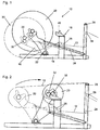
- FIG. 1 a simplified illustration of a device 10 for unwinding sheet material 12 is shown.
- the web-shaped material is withdrawn by at least one pair of delivery rollers not shown here in detail and supplied to a web-processing machine, also not shown.
- Such web-processing machines may be a printing machine, a tube or processing machine, among other things for paper, plastic or plastic fabric, which is usually made of polyolefin, or a sack or bag making machine that makes sacks or bags.
- the unwinding device has a machine frame 14, in which a first unwinding point 16 and a second unwinding point 18 are arranged.
- the first unwinding point consists of a pivotable Wickeltransporthebelpress 16, in which a new roll with web-shaped material 20 can be inserted.
- the winding transport lever pair 16 is pivotable about a pivot shaft 22 by means of a piston-cylinder arrangement 24, which is connected on one side to the machine frame 14 and on the opposite side to the winding transport lever pair.
- About the winding transport lever pair 16 of the winding 20 is pivoted from a receiving position shown in Figure 1 (dash-dotted line) in an unwinding position (solid line).
- FIG. 2 In the illustration according to FIG. 2 moreover, two different unwinding possibilities for the web-shaped material 12 are shown.
- the web-like material In one of the Abwickelities the web-like material is guided over the drain rollers 26 and 28, while in the alternative position, the web-like material 12 is withdrawn only via the take-off rollers 28.
- the winding 20 In both unwinding positions, the winding 20 can be transferred from the winding transport lever pair 16 to the stationary unwinding point 18 without the unwinding process having to be interrupted.
- FIGS. 3 and 4 In each case, a detail of the Wickeltransporthebelpases 16 is shown in two positions.
- a winding transport lever In the schematic sectional view according to FIG. 3 is shown part of a winding transport lever.
- a shaft 32 In a box-shaped receptacle 30, which is part of the winding transport lever not shown here, a shaft 32 is rotatably received on the outside of the winding transport lever in also not shown, a brake, in the present case, a pneumatic brake, arranged and fixedly connected to the shaft.
- a gear 34 is arranged on the shaft. This gear 34 meshes with a arranged on the winding shaft 36 of the recorded coil 20 gear 38th
- FIG. 3 It is shown how the winding shaft 36 is moved in the direction of arrow a when placing the roll 20 on the winding transport lever pair in the direction of the shaft 32.
- the gear pairing of the gears 34 and 36 As in FIG. 3 shown, engaged.
- the brake which is not shown here in detail, arranged on the winding transport lever 16 acts on the winding shaft 36 and thus on the winding 20, so that inadvertent rotation of the roll 20 due to uneven weight loading is prevented. Furthermore, the necessary web tension is maintained even during the removal of the sheet material 12 by the coupled brake.
- the toothing of the gears 34 and 38 is selected such that the gears engage in insertion of the winding shaft 36 in the winding transport lever pair 16 without further problems with each other.
- the tooth flanks are formed somewhat obliquely than in a conventional involute toothing, so that a, as shown in Figure 3 and FIG. 4 results in more acute-angled tooth shape.
- a cover 40 is provided, which is closed in a solid line and opened in dotted line.
- the cover 40 is hinged on one side about corresponding hinges 42. On the other side it is held by a metallic projection 42 with a magnet 44.
- the magnetic force is in this case adjusted so that with a corresponding pivoting of the Wickeltransporthebelpass 16, as in FIG. 4 is shown, the self-contained lid 40 automatically pivots in the direction of arrow b, so that the winding shaft 36 with pivoted cover 40 to the stationary unwinding point 18 (see. FIG. 2 ) can be handed over.
- FIG. 5 schematically a part of the winding shaft 36 is shown, which is stored here in the receptacle 46 of the stationary unwinding point 18.
- the winding shaft with the largely unwound winding 20 are slowed down otherwise.
- a slip-resistant friction lining for forming a friction brake 48 is provided on the receptacle 46.
- This covering may consist of a plastic or a natural material, such as leather, which has a high coefficient of friction in a pair of materials with steel.
- an additional hand-operated brake 50 is disposed laterally at the stationary unwind location.
- This manually adjustable brake 50 consists of two pivotable clamping jaws 52 which extend from the dashed position in FIG. 5 in an engaged position (solid line) are pivotable and there via a manually zudusbaren screw mechanism (not shown here) is adjustable.
Landscapes
- Replacement Of Web Rolls (AREA)
- Unwinding Webs (AREA)
Description
Die Erfindung betrifft eine Vorrichtung zum Abwickeln von bahnförmigem Material nach dem Oberbegriff des Anspruchs 1. Vorrichtungen zum Abwickeln von bahnförmigem Material werden üblicherweise bahnverarbeitenden Maschinen vorgeschaltet. Derartige Maschinen sind beispielsweise Schlauchmaschinen, die aus bahnförmigem Material Schläuche herstellen, Ventilzettelvorrichtungen für Sackherstellungsmaschinen oder Druckmaschinen jeglicher Art. Unter bahnförmigem Material können in diesem Zusammenhang unter anderem Flachbahnen oder Schlauchbahnen verstanden werden.The invention relates to a device for unwinding sheet material according to the preamble of claim 1. Devices for unwinding web material are usually upstream of web-processing machines. Such machines are, for example, hose machines that produce hoses of sheet material, valve sheet devices for sack making machines or printing presses of any kind. Under sheet material can be understood in this context inter alia, flat or tubular webs.
Derartige Vorrichtungen zum Abwickeln von bahnförmigem Material sind bereits in verschiedener Form bekannt. Eine besonders einfache Äusführungsform, die bereits umfassend eingesetzt wird, weist eine Abwickelstelle zur Aufnahme einer Wickelwelle für bahnförmiges Material, beispielsweise Geweberollen auf. Die hier bekannte Abwickelstelle besteht aus zwei parallelen Hubschwingen, in welche die Wickelwelle (mit dem darauf aufgebrachten Wickel bahnförmigen Materials) aufgenommen wird. Dabei wird die Wickelwelle seitlich in Klapplagern gelagert. An die über die Klapplager festgelegte Wickelwelle wird koaxial eine pneumatische Bremse angebunden. Über die pneumatische Bremse kann die erforderliche Bahnspannung erzeugt werden und die Maschine zum Rollenwechsel gestoppt werden.Such devices for unwinding sheet material are already known in various forms. A particularly simple Äusführungsform, which is already widely used, has an unwinding for receiving a winding shaft for web-shaped material, for example, fabric rolls. The unwinding point known here consists of two parallel lifting rockers, in which the winding shaft (with the winding applied thereto web-like material) is added. The winding shaft is mounted laterally in folding bearings. Coaxial with the winding shaft fixed via the folding bearing becomes a pneumatic brake tethered. The required web tension can be generated via the pneumatic brake and the machine can be stopped to change the reel.
Mit dieser bekannten Vorrichtung zum Abwickeln von bahnförmigem Material sind zum Wechsel der Wickel folgende Schritte zu absolvieren:
- Stoppen der Maschine
- Absenken der Hubschwinge
- Durchschneiden des bahnförmigen Materials
- Entnahme der leeren Wickelwelle
- Einbau der neuen vollen Wickelwelle
- Anheben der Hubschwinge
- Ankleben der Bahn
- Starten der Maschine.
- Stopping the machine
- Lowering the lifting rocker
- Cutting through the sheet material
- Removal of the empty winding shaft
- Installation of the new full winding shaft
- Lifting the lifting rocker
- Gluing the web
- Starting the machine.
Diese bekannte Vorrichtung zum Abwickeln von bahnförmigem Material hat den Vorteil, dass sie einfach und robust gebaut ist. Allerdings hat sie den Nachteil, dass das Auswechseln der Wickelwellen relativ zeitaufwendig ist.This known device for unwinding web-like material has the advantage that it is simple and robust. However, it has the disadvantage that the replacement of the winding shafts is relatively time consuming.
Aus der
Aufgabe der Erfindung ist es, eine einfach aufgebaute Vorrichtung zum Abwickeln von bahnförmigem Material derart weiterzubilden, dass sie einerseits immer noch einfach und kostengünstig aufgebaut ist, zum anderen aber hinsichtlich des Rollenwechsels einen einfachen, schnellen und sicheren Wechsel ermöglicht.The object of the invention is to develop a simply constructed device for unwinding web-like material in such a way that on the one hand it is still simple and inexpensive, but on the other hand enables a simple, quick and safe change with regard to the roll change.
Erfindungsgemäß wird diese Aufgabe ausgehend von einer Vorrichtung mit den Merkmalen des Oberbegriffs des Anspruchs 1 durch die Kombination mit den Merkmalen des kennzeichnenden Teils des Anspruchs 1 gelöst.This object is achieved on the basis of a device having the features of the preamble of claim 1 by the combination with the features of the characterizing part of claim 1.
Demnach weist die Vorrichtung zum Abwickeln von bahnförmigem Material eine erste und zumindest eine zweite Abwickelstelle auf, in welcher erste und zweite Wickel des bahnförmigen Materials rotierbar lagerbar sind, wobei eine Abwickelstelle ortsfest und die andere Abwickelstelle bewegbar in der Vorrichtung angeordnet sind. Erfindungsgemäß weist die bewegbare Abwickelstelle eine Bremse auf, die über eine Zahnradpaarung mit dem aufgelegten Wickel des bahnförmigen Materials koppelbar ist. Durch die Anbindung der Bremse mittels der Zahnradpaarung wird zum Einen die sichere Abbremsung des noch weitgehend vollen Wickels während des Abwickelns sichergestellt. Auch bei der Übergabe des Wickels an die zweite, ortsfeste Abwickelstelle bleibt der mit der ersten bewegbaren Abwickelstelle bewegte Wickel zum Anderen an die Bremse gekoppelt. Erst nach der Übergabe auf die ortsfeste Abwickelstelle wird die Zahnradpaarung getrennt, so dass die an der bewegbaren Abwickelstelle angeordnete Bremse nicht mehr im Eingriff mit dem übergebenen Wickel steht.Accordingly, the device for unwinding web-like material has a first and at least one second unwinding location, in which first and second reels of the web-shaped material are rotatably storable, one unwinding station being stationary and the other unwinding location being movably arranged in the device. According to the invention, the movable unwinding point on a brake which can be coupled via a gear pair with the wound winding of the web-shaped material. By the connection of the brake by means of the gear pairing on the one hand the secure braking of the still largely full roll is ensured during unwinding. Even with the transfer of the roll to the second, stationary unwinding the moving with the first movable unwinding winding to the other remains coupled to the brake. Only after the transfer to the stationary unwinding the gear pairing is separated, so that the arranged on the movable unwinding brake is no longer in engagement with the transferred winding.
Bevorzugte Ausgestaltungen der Erfindung ergeben sich aus den sich an den Hauptanspruch anschließenden Unteransprüchen.Preferred embodiments of the invention will become apparent from the subsequent claims to the main claim.
Demnach kann die bewegbare Abwickelstelle aus einem schwenkbaren Wickeltransporthebelpaar bestehen. In dieses Wickeltransporthebelpaar wird der volle Wickel gelegt, während gleichzeitig der nahezu abgewickelte Wickel auf der ortsfesten Abwickelstelle lagert und von dieser abgewickelt wird.Accordingly, the movable unwinding may consist of a pivotable winding transport lever pair. In this Wickeltransporthebelpaar the full winding is placed, while at the same time stores the almost unwound winding on the stationary unwinding and unwound from this.
Vorteilhaft ist seitlich an einem Wickeltransporthebel des Wickeltransporthebelpaares eine Bremse angeordnet, wobei diese mit einer in dem Wickeltransporthebel gelagerten Welle verbunden ist, auf der ein Zahnrad sitzt, das mit einem zweiten Zahnrad einer Zahnradpaarung in Eingriff stehen kann, das an der Wickelwelle des im Wickeltransporthebelpaar aufgenommenen Wickels angeordnet ist.A brake is advantageously arranged laterally on a winding transport lever of the winding transport lever pair, this being connected to a shaft mounted in the winding transport lever on which a toothed wheel can engage a second gear of a gear pair which is received on the winding shaft of the winding transport lever pair Wickels is arranged.
Vorteilhaft ist die Zahnform und/oder Anordnung der Zahnräder der Zahnradpaarung so gewählt, dass beim Einlegen oder der Übergabe des Wickels die Zahnräder der Zahnradpaarung zum Ankoppeln bzw. Abkoppeln im Wesentlichen radial ein- und auskoppeln.Advantageously, the tooth shape and / or arrangement of the gears of the gear pairing is chosen so that when inserting or transferring the coil, the gears of the gear pair for coupling or decoupling substantially radially on and decouple.
Besonders vorteilhaft ist die Zahnradpaarung in dem Wickeltransporthebel über eine Abdeckung abdeckbar. Diese dient einerseits zum Schutz der Zahnradpaarung und andererseits unter dem Gesichtspunkt der Maschinensicherheit. Dabei kann die Abdeckung der Zahnradpaarung aus einem einseitig schwenkbar angelenkten Deckel bestehen, dessen schwenkbare Seite über Magneten in der geschlossenen Stellung fixierbar ist. Nach Übergabe der Wickelwelle in die ortsfeste Abwickelposition öffnet sich die Abdeckung automatisch beim Zurückfahren des Wickeltransporthebelpaares.Particularly advantageously, the gear pair in the winding transport lever can be covered by a cover. This serves on the one hand to protect the gear pair and on the other hand from the point of view of machine safety. In this case, the cover of the gear pair may consist of a unilaterally pivotally hinged lid whose pivotable side can be fixed by means of magnets in the closed position. After transfer of the winding shaft in the stationary unwinding position, the cover opens automatically when returning the Wickeltransporthebelpaares.
Da bei Übergabe des Wickels auf die ortsfeste Abwickelstelle die an der bewegbaren Abwickelstelle vorhandene Bremse nicht mehr in Eingriff mit dem Wickel steht, weist die ortsfeste Abwickelstelle im Bereich ihrer Wickelwellenaufnahme eine Beschichtung aus einem die Rotation der Wickelwelle abbremsenden Material auf. Hierdurch wird während des weiteren Abwickelns der Bahn in der Regel schon eine hinreichende Bremskraft auf den Wickel aufgeprägt, so dass weitere Bremseinrichtungen überflüssig sind. Sollte die Bremskraft allerdings nicht ausreichen, kann gemäß einer weiteren Ausgestaltung der Erfindung zumindest an einer Seite der ortsfesten Abwickelstelle eine mit der Wickelwelle unmittelbar zusammenwirkende Reibbremse angeordnet sein.Since, when transferring the roll to the stationary unwinding station, the brake present on the movable unwinding station is no longer in engagement with the reel, the stationary unwinding point has a coating of a material that decelerates the rotation of the reel shaft in the region of its reel shaft receptacle. As a result, during the further unwinding of the web usually a sufficient braking force is already impressed on the winding, so that further braking devices are superfluous. However, should the braking force not be sufficient, according to a further embodiment of the invention, a friction brake directly interacting with the winding shaft can be arranged at least on one side of the stationary unwinding location.
Schließlich sind mechanische Sicherungen zur Sicherung des Wickels an den Wickeltransporthebeln vorgesehen, die eine separate mechanische Sicherung der Wickelwelle in dem Wickeltransporthebelpaar gegen ein Herausfallen gewährleisten.Finally, mechanical safeguards for securing the roll to the winding transport levers are provided, which ensure a separate mechanical securing of the winding shaft in the winding transport lever pair against falling out.
Weitere Einzelheiten, Vorteile und Merkmale der Erfindung ergeben sich aus einem in der Zeichnung dargestellten Ausführungsbeispiel. Es zeigen:
- Figur 1:
- eine schematische Seitenansicht der ersten Ausführungsvariante der erfindungsgemäßen Abwickelvorrichtung,
- Figur 2:
- eine Darstellung der Vorrichtung gemäß
Figur 1 in einer anderen Arbeitsposition, - Figuren 3 und 4:
- Detaildarstellungen eines Aufnahmekastens mit der Zahnradpaarung und der zugehörigen Abdeckung und
- Figur 5:
- eine Detaildarstellung eines Teils der erfindungsgemäßen Vorrichtung, in welcher die Wickelwelle eines Wickels in der Aufnahme der ortsfesten Abwickelstelle einschließlich der Bremsbeläge und der zusätzlichen zweiten Bremse gezeigt ist.
- FIG. 1:
- a schematic side view of the first embodiment of the unwinding device according to the invention,
- FIG. 2:
- a representation of the device according to
FIG. 1 in another job position, - FIGS. 3 and 4:
- Details of a receiving box with the gear pairing and the associated cover and
- FIG. 5:
- a detailed view of a portion of the device according to the invention, in which the winding shaft of a coil in the receptacle of the stationary unwinding point including the brake pads and the additional second brake is shown.
In der
Die Abwickelvorrichtung weist ein Maschinengestell 14 auf, in welchem eine erste Abwickelstelle 16 und eine zweite Abwickelstelle 18 angeordnet sind. Die erste Abwickelstelle besteht aus einem schwenkbaren Wickeltransporthebelpaar 16, in welchem ein neuer Wickel mit bahnförmigen Material 20 einlegbar ist. Das Wickeltransporthebelpaar 16 ist um eine Schwenkwelle 22 mittels einer Kolbenzylinderanordnung 24, die einseitig mit dem Maschinengestell 14 und auf der gegenüberliegenden Seite mit dem Wickeltransporthebelpaar verbunden ist, verschwenkbar. Über das Wickeltransporthebelpaar 16 wird der Wickel 20 von einer in der Figur 1 dargestellten Aufnahmeposition (strichpunktierte Linie) in eine Abwickelposition (durchgezogene Linie) verschwenkt.The unwinding device has a
Beim Abwickeln wird das bahnförmige Material über im Maschinengestell 14 angeordnete Ablaufwalzen 26 bzw. 28 geführt. Soweit das bahnförmige Material 12 weitgehend vom Wickel 20 abgewickelt ist, was über einen hier nicht näher dargestellten Sensor überprüft wird, wird das Wickeltransporthebelpaar 16 von der strichpunktierten Stellung gemäß
In der Darstellung gemäß
In den
In
Die Verzahnung der Zahnräder 34 und 38 ist derart gewählt, dass die Zahnräder bei Einsetzen der Wickelwelle 36 in das Wickeltransporthebelpaar 16 ohne weitere Probleme ineinander eingreifen. Hierzu sind die Zahnflanken etwas schräger ausgebildet als bei einer üblichen Evolventenverzahnung, so dass sich eine, wie in Figur 3 und
Wie in
In
Zusätzlich ist für den Fall, dass die Reibbremse 48 alleine keine genügende Bremswirkung aufbringt, eine zusätzliche handbetätigte Bremse 50 seitlich an der ortsfesten Abwickelstelle angeordnet. Diese manuell einstellbare Bremse 50 besteht aus zwei schwenkbaren Klemmbacken 52, die von der gestrichelten Stellung in
Mit der zuvor vorgestellten Abwickelvorrichtung 10 zum Abwickeln von bahnförmigem Material 12 ist vorteilhaft ein Auflegen eines neuen Wickels 20 ohne ein Abstoppen der Abwickelvorrichtung möglich. Das Handling der Wickel 20 erfolgt mit der hier vorgestellten Abwickelvorrichtung 10 wie folgt:
- Vor Anfahren der Maschine wird ein neuer
Wickel 20 indas Wickeltransporthebelpaar 16 eingelegt; - Anheben des Winkeltransporthebelpaars 16 in die erste Arbeitsposition und Beginn des Abwickelns des Wickels 20;
- Abwickeln des Wickels 20 bis ca. zu einem Durchmesser von ca. 600 mm;
- Weiterschwenken des Wickeltransporthebelpaars 16 in die zweite Arbeitsposition;
- Ablage des Restwickels auf der ortsfesten Abwickelstelle 18;
- Abwicklung des Restwickels bis die Wickelwelle leergelaufen ist;
- gleichzeitiges Zurückschwenken des Wickeltransporthebelpaares 16;
- Aufnahme eines neuen Wickels (wie zuvor beschrieben) und;
- Anheben der Hubschwinge in die erste Arbeitsposition und Abwarten bis die Restrolle in der ortsfesten Abwickelstelle 18 leergelaufen ist;
- Stoppen der Maschine und der Abwickelvorrichtung;
- Abwickeln einer Lose;
- Durchschneiden der Bahn;
Verlegung der Bahn 12 zum neuenWickel 20, Ankleben der Bahn anden Wickel 20 und- Starten der Maschine und der
Abwickelvorrichtung 10.
- Before starting the machine, a new winding 20 is inserted into the winding
transport lever pair 16; - Lifting the
Winkeltransporthebelpaars 16 in the first working position and start of unwinding of theroll 20; - Unwinding the
roll 20 to about a diameter of about 600 mm; - Further pivoting the
Wickeltransporthebelpaars 16 in the second working position; - Storage of the remaining roll on the
stationary unwinding 18; - Settlement of the remaining roll until the winding shaft has run empty;
- simultaneous pivoting back of the
Wickeltransporthebelpaares 16; - Receiving a new roll (as previously described) and;
- Lifting the lifting rocker to the first working position and waiting until the residual roll in the
stationary unwinding station 18 has run empty; - Stopping the machine and the unwinding device;
- Unwinding a lot;
- Cutting the web;
- Laying the
web 12 to thenew roll 20, adhering the web to the winding 20 and - Starting the machine and unwind 10.
Claims (10)
- Device (10) for unwinding web-shaped material (12), having one first and at least one second unwinding position (16, 18) in which first and second rolls (20) of the web-shaped material (12) are rotatably mountable, wherein in the device (10) one unwinding position (18) is disposed so as to be locationally fixed and the other unwinding position (16) is disposed so as to be movable, characterized in that
the movable unwinding position (16) has a brake which by way of a pair of gears (34, 36) is coupleable to the loaded roll (20) of the web-shaped material (12). - Device according to Claim 1, characterized in that the movable unwinding position (16) is composed of a pair of pivotable roll transport levers.
- Device according to Claim 2, characterized in that the brake is disposed laterally on one roll transport lever of the pair of roll transport levers (16), wherein said brake is connected to a shaft (32) which is mounted in the roll transport lever, a gear wheel (34) which is capable of meshing with a second gear wheel (38) of a pair of gears, which is disposed on the winding shaft (36) of the roll (20) which is received in the pair of roll transport levers, sitting on said shaft (32).
- Device according to Claim 2 or 3, characterized in that the tooth shape and/or the arrangement of the gear wheels is chosen such that the gear wheels (34, 38) of the pair of gears upon insertion or transfer of the roll (20), for coupling and decoupling, respectively, engage in a substantially trouble-free manner.
- Device according to one of Claims 1 to 4, characterized in that the pair of gears (34, 38) in the roll transport lever are coverable by a cover (40).
- Device according to Claim 5, characterized in that the cover of the pair of gears (34, 38) has a pivotable lid (40) which is unilaterally articulated, the pivotable side of which by way of magnets (44) is fixable in the closed position.
- Device according to one of the preceding claims, characterized in that the locationally fixed unwinding position (18) in the region of the winding shaft receptacle (46) thereof has a coating (48) of a material which decelerates the rotation of the winding shaft.
- Device according to one of the preceding claims, characterized in that a friction brake (50) which directly interacts with the winding shaft (36) is disposed at least on one side of the locationally fixed unwinding position (18).
- Device according to Claim 8, characterized in that the friction brake (50) is composed of manually adjustable clamping jaws (52) which are placeable around the shaft (36).
- Device according to one of the preceding claims, characterized in that mechanical safeguards for securing the roll (20) on the roll transport levers (16) are provided.
Applications Claiming Priority (2)
| Application Number | Priority Date | Filing Date | Title |
|---|---|---|---|
| DE201210013459 DE102012013459A1 (en) | 2012-07-04 | 2012-07-04 | Device for unwinding sheet material |
| PCT/EP2013/001476 WO2014005661A1 (en) | 2012-07-04 | 2013-05-17 | Device for unwinding web material |
Publications (2)
| Publication Number | Publication Date |
|---|---|
| EP2828186A1 EP2828186A1 (en) | 2015-01-28 |
| EP2828186B1 true EP2828186B1 (en) | 2016-07-13 |
Family
ID=48570049
Family Applications (1)
| Application Number | Title | Priority Date | Filing Date |
|---|---|---|---|
| EP13726421.4A Not-in-force EP2828186B1 (en) | 2012-07-04 | 2013-05-17 | Device for unwinding web material |
Country Status (3)
| Country | Link |
|---|---|
| EP (1) | EP2828186B1 (en) |
| DE (1) | DE102012013459A1 (en) |
| WO (1) | WO2014005661A1 (en) |
Families Citing this family (5)
| Publication number | Priority date | Publication date | Assignee | Title |
|---|---|---|---|---|
| CN106829581B (en) * | 2016-12-20 | 2018-09-14 | 芜湖市天申新材料科技有限公司 | A kind of paper roll frame of packaging convenient installation paper roll used for paper processing |
| DE102017118312A1 (en) * | 2017-08-11 | 2019-02-14 | Voith Patent Gmbh | unrolling |
| JP7462216B2 (en) * | 2020-04-27 | 2024-04-05 | パナソニックIpマネジメント株式会社 | Reel holding device |
| JP7548049B2 (en) * | 2021-02-18 | 2024-09-10 | セイコーエプソン株式会社 | Media supply device, recording device |
| US12384640B2 (en) | 2022-08-17 | 2025-08-12 | Bw Converting, Inc. | Single web automatic splicing unwind machine and method |
Family Cites Families (6)
| Publication number | Priority date | Publication date | Assignee | Title |
|---|---|---|---|---|
| AT118883B (en) * | 1927-08-05 | 1930-08-25 | Bates Valve Bag Corp | Unwinding device for paper supply rolls. |
| US2094896A (en) * | 1935-06-04 | 1937-10-05 | Hoague Sprague Corp | Coil supporting and splicing mechanism |
| IT1200273B (en) * | 1986-07-22 | 1989-01-12 | Mira Lanza Spa | DEVICE FOR JOINTING AND RAPID CHANGE OF REELS IN REELING MACHINES |
| US5335870A (en) * | 1992-08-26 | 1994-08-09 | Martin Automatic, Inc. | Flying paster |
| DE29915280U1 (en) * | 1999-09-01 | 1999-12-23 | Maschinenfabrik Goebel Gmbh, 64293 Darmstadt | Establishment with supply roll |
| DE102008022697A1 (en) * | 2008-05-07 | 2009-12-10 | Windmöller & Hölscher Kg | Device and method for unwinding web-like material and web-processing machine |
-
2012
- 2012-07-04 DE DE201210013459 patent/DE102012013459A1/en not_active Withdrawn
-
2013
- 2013-05-17 WO PCT/EP2013/001476 patent/WO2014005661A1/en not_active Ceased
- 2013-05-17 EP EP13726421.4A patent/EP2828186B1/en not_active Not-in-force
Also Published As
| Publication number | Publication date |
|---|---|
| EP2828186A1 (en) | 2015-01-28 |
| WO2014005661A1 (en) | 2014-01-09 |
| DE102012013459A1 (en) | 2014-01-09 |
Similar Documents
| Publication | Publication Date | Title |
|---|---|---|
| WO2014005661A1 (en) | Device for unwinding web material | |
| DE102010026228B3 (en) | Rolling machine for automatically stretching winding films utilized for packing objects, has turntable arranged in support and rotated by motive force source for individually gripping paper roll or winding shaft in gripper | |
| AT16593U1 (en) | Winder for winding a fibrous web | |
| EP1602269A1 (en) | Baler with a downstream-arranged balewrapper | |
| EP0030402B1 (en) | Device for winding cut strips | |
| EP2050699A2 (en) | Method for calculating the diameter of a winding of web material on a roll and winding control system | |
| DE2335453C2 (en) | Device for removing the film from a film cartridge | |
| DE102010063466A1 (en) | Apparatus for processing a paper web to be used for the production of rod-shaped smoking articles | |
| EP2313335A1 (en) | Device and method for unwinding and/or winding up webs of material | |
| EP2285719A1 (en) | Device and method for winding strip-shaped material and strip processing machine | |
| DE3914776A1 (en) | METHOD AND DEVICE FOR WINDING AND CROSS-CUTTING A RUNNING GOODS | |
| DE2649289A1 (en) | ROLL CHANGING DEVICE IN A REEL DEVICE FOR TRACKS | |
| AT512098A2 (en) | A method of calculating the initial diameter of a web winding on a roll after a roll change | |
| EP2920096A1 (en) | Winding apparatus | |
| EP0699607A1 (en) | Method and device for spreading a cloth | |
| DE102013015866B4 (en) | Roll-off system for a roll of paper as well as for a filling material production machine | |
| DE102007010094A1 (en) | Rolling up device for textile materials comprises a device for storing a winding body that consists of roller-like storage elements in the form of support rollers, drive rollers and/or pressure rollers acting externally on the winding body | |
| DE2063018B2 (en) | Device for eliminating the curvature of the roll in a paper web unwound from a supply roll | |
| WO2015055703A1 (en) | Winding device for winding a web-shaped material and method for changing a spool in a winding device | |
| DE10243464B4 (en) | Method and device for packaging a material web roll | |
| DE20321534U1 (en) | System and apparatus for preparing a reel for flying reel change, for detecting a web and for applying a double-sided adhesive tape on a surface | |
| DE102017105298A1 (en) | compounding plant | |
| DE2812829A1 (en) | WINDING DEVICE FOR WINDING A RAIL-SHAPED AREA ON A WINDING CORE | |
| DE10235784A1 (en) | Winding reel preparation for flying change of reels in printing machine involves applying double-sided adhesive tape between beginning of paper web and subjacent web layer of winding reel | |
| DE4321278A1 (en) | Marking the yarn end on bobbins - uses a marking strip wound into the last few turns |
Legal Events
| Date | Code | Title | Description |
|---|---|---|---|
| PUAI | Public reference made under article 153(3) epc to a published international application that has entered the european phase |
Free format text: ORIGINAL CODE: 0009012 |
|
| 17P | Request for examination filed |
Effective date: 20140929 |
|
| AK | Designated contracting states |
Kind code of ref document: A1 Designated state(s): AL AT BE BG CH CY CZ DE DK EE ES FI FR GB GR HR HU IE IS IT LI LT LU LV MC MK MT NL NO PL PT RO RS SE SI SK SM TR |
|
| AX | Request for extension of the european patent |
Extension state: BA ME |
|
| RIN1 | Information on inventor provided before grant (corrected) |
Inventor name: TILLMANN, GUIDO |
|
| DAX | Request for extension of the european patent (deleted) | ||
| GRAP | Despatch of communication of intention to grant a patent |
Free format text: ORIGINAL CODE: EPIDOSNIGR1 |
|
| INTG | Intention to grant announced |
Effective date: 20160127 |
|
| GRAS | Grant fee paid |
Free format text: ORIGINAL CODE: EPIDOSNIGR3 |
|
| GRAA | (expected) grant |
Free format text: ORIGINAL CODE: 0009210 |
|
| AK | Designated contracting states |
Kind code of ref document: B1 Designated state(s): AL AT BE BG CH CY CZ DE DK EE ES FI FR GB GR HR HU IE IS IT LI LT LU LV MC MK MT NL NO PL PT RO RS SE SI SK SM TR |
|
| REG | Reference to a national code |
Ref country code: GB Ref legal event code: FG4D Free format text: NOT ENGLISH |
|
| REG | Reference to a national code |
Ref country code: AT Ref legal event code: REF Ref document number: 812123 Country of ref document: AT Kind code of ref document: T Effective date: 20160715 Ref country code: CH Ref legal event code: EP |
|
| REG | Reference to a national code |
Ref country code: IE Ref legal event code: FG4D Free format text: LANGUAGE OF EP DOCUMENT: GERMAN |
|
| REG | Reference to a national code |
Ref country code: DE Ref legal event code: R096 Ref document number: 502013003722 Country of ref document: DE |
|
| REG | Reference to a national code |
Ref country code: LT Ref legal event code: MG4D |
|
| REG | Reference to a national code |
Ref country code: NL Ref legal event code: MP Effective date: 20160713 |
|
| PG25 | Lapsed in a contracting state [announced via postgrant information from national office to epo] |
Ref country code: IS Free format text: LAPSE BECAUSE OF FAILURE TO SUBMIT A TRANSLATION OF THE DESCRIPTION OR TO PAY THE FEE WITHIN THE PRESCRIBED TIME-LIMIT Effective date: 20161113 Ref country code: FI Free format text: LAPSE BECAUSE OF FAILURE TO SUBMIT A TRANSLATION OF THE DESCRIPTION OR TO PAY THE FEE WITHIN THE PRESCRIBED TIME-LIMIT Effective date: 20160713 Ref country code: NL Free format text: LAPSE BECAUSE OF FAILURE TO SUBMIT A TRANSLATION OF THE DESCRIPTION OR TO PAY THE FEE WITHIN THE PRESCRIBED TIME-LIMIT Effective date: 20160713 Ref country code: RS Free format text: LAPSE BECAUSE OF FAILURE TO SUBMIT A TRANSLATION OF THE DESCRIPTION OR TO PAY THE FEE WITHIN THE PRESCRIBED TIME-LIMIT Effective date: 20160713 Ref country code: IT Free format text: LAPSE BECAUSE OF FAILURE TO SUBMIT A TRANSLATION OF THE DESCRIPTION OR TO PAY THE FEE WITHIN THE PRESCRIBED TIME-LIMIT Effective date: 20160713 Ref country code: LT Free format text: LAPSE BECAUSE OF FAILURE TO SUBMIT A TRANSLATION OF THE DESCRIPTION OR TO PAY THE FEE WITHIN THE PRESCRIBED TIME-LIMIT Effective date: 20160713 Ref country code: HR Free format text: LAPSE BECAUSE OF FAILURE TO SUBMIT A TRANSLATION OF THE DESCRIPTION OR TO PAY THE FEE WITHIN THE PRESCRIBED TIME-LIMIT Effective date: 20160713 Ref country code: NO Free format text: LAPSE BECAUSE OF FAILURE TO SUBMIT A TRANSLATION OF THE DESCRIPTION OR TO PAY THE FEE WITHIN THE PRESCRIBED TIME-LIMIT Effective date: 20161013 |
|
| PG25 | Lapsed in a contracting state [announced via postgrant information from national office to epo] |
Ref country code: GR Free format text: LAPSE BECAUSE OF FAILURE TO SUBMIT A TRANSLATION OF THE DESCRIPTION OR TO PAY THE FEE WITHIN THE PRESCRIBED TIME-LIMIT Effective date: 20161014 Ref country code: LV Free format text: LAPSE BECAUSE OF FAILURE TO SUBMIT A TRANSLATION OF THE DESCRIPTION OR TO PAY THE FEE WITHIN THE PRESCRIBED TIME-LIMIT Effective date: 20160713 Ref country code: PL Free format text: LAPSE BECAUSE OF FAILURE TO SUBMIT A TRANSLATION OF THE DESCRIPTION OR TO PAY THE FEE WITHIN THE PRESCRIBED TIME-LIMIT Effective date: 20160713 Ref country code: PT Free format text: LAPSE BECAUSE OF FAILURE TO SUBMIT A TRANSLATION OF THE DESCRIPTION OR TO PAY THE FEE WITHIN THE PRESCRIBED TIME-LIMIT Effective date: 20161114 Ref country code: ES Free format text: LAPSE BECAUSE OF FAILURE TO SUBMIT A TRANSLATION OF THE DESCRIPTION OR TO PAY THE FEE WITHIN THE PRESCRIBED TIME-LIMIT Effective date: 20160713 Ref country code: SE Free format text: LAPSE BECAUSE OF FAILURE TO SUBMIT A TRANSLATION OF THE DESCRIPTION OR TO PAY THE FEE WITHIN THE PRESCRIBED TIME-LIMIT Effective date: 20160713 |
|
| REG | Reference to a national code |
Ref country code: DE Ref legal event code: R097 Ref document number: 502013003722 Country of ref document: DE |
|
| PG25 | Lapsed in a contracting state [announced via postgrant information from national office to epo] |
Ref country code: RO Free format text: LAPSE BECAUSE OF FAILURE TO SUBMIT A TRANSLATION OF THE DESCRIPTION OR TO PAY THE FEE WITHIN THE PRESCRIBED TIME-LIMIT Effective date: 20160713 Ref country code: EE Free format text: LAPSE BECAUSE OF FAILURE TO SUBMIT A TRANSLATION OF THE DESCRIPTION OR TO PAY THE FEE WITHIN THE PRESCRIBED TIME-LIMIT Effective date: 20160713 |
|
| PLBE | No opposition filed within time limit |
Free format text: ORIGINAL CODE: 0009261 |
|
| STAA | Information on the status of an ep patent application or granted ep patent |
Free format text: STATUS: NO OPPOSITION FILED WITHIN TIME LIMIT |
|
| PG25 | Lapsed in a contracting state [announced via postgrant information from national office to epo] |
Ref country code: CZ Free format text: LAPSE BECAUSE OF FAILURE TO SUBMIT A TRANSLATION OF THE DESCRIPTION OR TO PAY THE FEE WITHIN THE PRESCRIBED TIME-LIMIT Effective date: 20160713 Ref country code: DK Free format text: LAPSE BECAUSE OF FAILURE TO SUBMIT A TRANSLATION OF THE DESCRIPTION OR TO PAY THE FEE WITHIN THE PRESCRIBED TIME-LIMIT Effective date: 20160713 Ref country code: SK Free format text: LAPSE BECAUSE OF FAILURE TO SUBMIT A TRANSLATION OF THE DESCRIPTION OR TO PAY THE FEE WITHIN THE PRESCRIBED TIME-LIMIT Effective date: 20160713 Ref country code: BG Free format text: LAPSE BECAUSE OF FAILURE TO SUBMIT A TRANSLATION OF THE DESCRIPTION OR TO PAY THE FEE WITHIN THE PRESCRIBED TIME-LIMIT Effective date: 20161013 Ref country code: SM Free format text: LAPSE BECAUSE OF FAILURE TO SUBMIT A TRANSLATION OF THE DESCRIPTION OR TO PAY THE FEE WITHIN THE PRESCRIBED TIME-LIMIT Effective date: 20160713 |
|
| 26N | No opposition filed |
Effective date: 20170418 |
|
| PG25 | Lapsed in a contracting state [announced via postgrant information from national office to epo] |
Ref country code: SI Free format text: LAPSE BECAUSE OF FAILURE TO SUBMIT A TRANSLATION OF THE DESCRIPTION OR TO PAY THE FEE WITHIN THE PRESCRIBED TIME-LIMIT Effective date: 20160713 Ref country code: LU Free format text: LAPSE BECAUSE OF NON-PAYMENT OF DUE FEES Effective date: 20170531 |
|
| REG | Reference to a national code |
Ref country code: DE Ref legal event code: R119 Ref document number: 502013003722 Country of ref document: DE |
|
| REG | Reference to a national code |
Ref country code: CH Ref legal event code: PL |
|
| GBPC | Gb: european patent ceased through non-payment of renewal fee |
Effective date: 20170517 |
|
| PG25 | Lapsed in a contracting state [announced via postgrant information from national office to epo] |
Ref country code: MC Free format text: LAPSE BECAUSE OF FAILURE TO SUBMIT A TRANSLATION OF THE DESCRIPTION OR TO PAY THE FEE WITHIN THE PRESCRIBED TIME-LIMIT Effective date: 20160713 |
|
| REG | Reference to a national code |
Ref country code: IE Ref legal event code: MM4A |
|
| PG25 | Lapsed in a contracting state [announced via postgrant information from national office to epo] |
Ref country code: CH Free format text: LAPSE BECAUSE OF NON-PAYMENT OF DUE FEES Effective date: 20170531 Ref country code: LI Free format text: LAPSE BECAUSE OF NON-PAYMENT OF DUE FEES Effective date: 20170531 |
|
| REG | Reference to a national code |
Ref country code: FR Ref legal event code: ST Effective date: 20180131 |
|
| PG25 | Lapsed in a contracting state [announced via postgrant information from national office to epo] |
Ref country code: LU Free format text: LAPSE BECAUSE OF NON-PAYMENT OF DUE FEES Effective date: 20170517 |
|
| REG | Reference to a national code |
Ref country code: BE Ref legal event code: MM Effective date: 20170531 |
|
| PG25 | Lapsed in a contracting state [announced via postgrant information from national office to epo] |
Ref country code: IE Free format text: LAPSE BECAUSE OF NON-PAYMENT OF DUE FEES Effective date: 20170517 Ref country code: GB Free format text: LAPSE BECAUSE OF NON-PAYMENT OF DUE FEES Effective date: 20170517 Ref country code: DE Free format text: LAPSE BECAUSE OF NON-PAYMENT OF DUE FEES Effective date: 20171201 |
|
| PG25 | Lapsed in a contracting state [announced via postgrant information from national office to epo] |
Ref country code: FR Free format text: LAPSE BECAUSE OF NON-PAYMENT OF DUE FEES Effective date: 20170531 |
|
| PG25 | Lapsed in a contracting state [announced via postgrant information from national office to epo] |
Ref country code: BE Free format text: LAPSE BECAUSE OF NON-PAYMENT OF DUE FEES Effective date: 20170531 |
|
| PG25 | Lapsed in a contracting state [announced via postgrant information from national office to epo] |
Ref country code: MT Free format text: LAPSE BECAUSE OF FAILURE TO SUBMIT A TRANSLATION OF THE DESCRIPTION OR TO PAY THE FEE WITHIN THE PRESCRIBED TIME-LIMIT Effective date: 20160713 |
|
| PG25 | Lapsed in a contracting state [announced via postgrant information from national office to epo] |
Ref country code: AL Free format text: LAPSE BECAUSE OF FAILURE TO SUBMIT A TRANSLATION OF THE DESCRIPTION OR TO PAY THE FEE WITHIN THE PRESCRIBED TIME-LIMIT Effective date: 20160713 |
|
| PG25 | Lapsed in a contracting state [announced via postgrant information from national office to epo] |
Ref country code: HU Free format text: LAPSE BECAUSE OF FAILURE TO SUBMIT A TRANSLATION OF THE DESCRIPTION OR TO PAY THE FEE WITHIN THE PRESCRIBED TIME-LIMIT; INVALID AB INITIO Effective date: 20130517 |
|
| REG | Reference to a national code |
Ref country code: AT Ref legal event code: MM01 Ref document number: 812123 Country of ref document: AT Kind code of ref document: T Effective date: 20180517 |
|
| PG25 | Lapsed in a contracting state [announced via postgrant information from national office to epo] |
Ref country code: CY Free format text: LAPSE BECAUSE OF FAILURE TO SUBMIT A TRANSLATION OF THE DESCRIPTION OR TO PAY THE FEE WITHIN THE PRESCRIBED TIME-LIMIT Effective date: 20160713 Ref country code: AT Free format text: LAPSE BECAUSE OF NON-PAYMENT OF DUE FEES Effective date: 20180517 |
|
| PG25 | Lapsed in a contracting state [announced via postgrant information from national office to epo] |
Ref country code: MK Free format text: LAPSE BECAUSE OF FAILURE TO SUBMIT A TRANSLATION OF THE DESCRIPTION OR TO PAY THE FEE WITHIN THE PRESCRIBED TIME-LIMIT Effective date: 20160713 |
|
| PG25 | Lapsed in a contracting state [announced via postgrant information from national office to epo] |
Ref country code: TR Free format text: LAPSE BECAUSE OF FAILURE TO SUBMIT A TRANSLATION OF THE DESCRIPTION OR TO PAY THE FEE WITHIN THE PRESCRIBED TIME-LIMIT Effective date: 20160713 |