EP2827964B1 - Rotating separator - Google Patents
Rotating separator Download PDFInfo
- Publication number
- EP2827964B1 EP2827964B1 EP13716187.3A EP13716187A EP2827964B1 EP 2827964 B1 EP2827964 B1 EP 2827964B1 EP 13716187 A EP13716187 A EP 13716187A EP 2827964 B1 EP2827964 B1 EP 2827964B1
- Authority
- EP
- European Patent Office
- Prior art keywords
- rotating container
- filtrate
- retentate
- screw
- container
- Prior art date
- Legal status (The legal status is an assumption and is not a legal conclusion. Google has not performed a legal analysis and makes no representation as to the accuracy of the status listed.)
- Active
Links
- 239000000706 filtrate Substances 0.000 claims description 119
- 239000012465 retentate Substances 0.000 claims description 84
- 239000002002 slurry Substances 0.000 claims description 61
- 239000007787 solid Substances 0.000 claims description 33
- 239000007788 liquid Substances 0.000 claims description 28
- 238000000034 method Methods 0.000 claims description 25
- 239000002253 acid Substances 0.000 claims description 11
- 238000004140 cleaning Methods 0.000 claims description 10
- 230000005484 gravity Effects 0.000 claims description 8
- 230000001360 synchronised effect Effects 0.000 claims description 7
- 238000002156 mixing Methods 0.000 claims description 4
- 238000003825 pressing Methods 0.000 claims description 3
- 238000007599 discharging Methods 0.000 claims 1
- 238000000926 separation method Methods 0.000 description 18
- 230000032258 transport Effects 0.000 description 17
- 239000000463 material Substances 0.000 description 16
- 239000004744 fabric Substances 0.000 description 10
- 230000008569 process Effects 0.000 description 10
- 239000010828 animal waste Substances 0.000 description 6
- 238000005406 washing Methods 0.000 description 6
- 241000237858 Gastropoda Species 0.000 description 4
- 239000012530 fluid Substances 0.000 description 4
- 239000002245 particle Substances 0.000 description 4
- 239000006096 absorbing agent Substances 0.000 description 3
- 239000012065 filter cake Substances 0.000 description 3
- BHEPBYXIRTUNPN-UHFFFAOYSA-N hydridophosphorus(.) (triplet) Chemical compound [PH] BHEPBYXIRTUNPN-UHFFFAOYSA-N 0.000 description 3
- 230000001105 regulatory effect Effects 0.000 description 3
- 206010053567 Coagulopathies Diseases 0.000 description 2
- XLYOFNOQVPJJNP-ZSJDYOACSA-N Heavy water Chemical compound [2H]O[2H] XLYOFNOQVPJJNP-ZSJDYOACSA-N 0.000 description 2
- 241001465754 Metazoa Species 0.000 description 2
- 229910000831 Steel Inorganic materials 0.000 description 2
- 230000035602 clotting Effects 0.000 description 2
- 210000003608 fece Anatomy 0.000 description 2
- 239000010871 livestock manure Substances 0.000 description 2
- 230000007246 mechanism Effects 0.000 description 2
- 239000000203 mixture Substances 0.000 description 2
- 230000010355 oscillation Effects 0.000 description 2
- 238000005086 pumping Methods 0.000 description 2
- 238000004064 recycling Methods 0.000 description 2
- 239000010959 steel Substances 0.000 description 2
- 238000002604 ultrasonography Methods 0.000 description 2
- 239000002351 wastewater Substances 0.000 description 2
- 230000009471 action Effects 0.000 description 1
- CKMXBZGNNVIXHC-UHFFFAOYSA-L ammonium magnesium phosphate hexahydrate Chemical compound [NH4+].O.O.O.O.O.O.[Mg+2].[O-]P([O-])([O-])=O CKMXBZGNNVIXHC-UHFFFAOYSA-L 0.000 description 1
- 230000015572 biosynthetic process Effects 0.000 description 1
- 230000015556 catabolic process Effects 0.000 description 1
- 239000002361 compost Substances 0.000 description 1
- 230000001276 controlling effect Effects 0.000 description 1
- 230000003247 decreasing effect Effects 0.000 description 1
- 230000018044 dehydration Effects 0.000 description 1
- 238000006297 dehydration reaction Methods 0.000 description 1
- 238000009826 distribution Methods 0.000 description 1
- 230000000694 effects Effects 0.000 description 1
- 230000005611 electricity Effects 0.000 description 1
- 239000006194 liquid suspension Substances 0.000 description 1
- 238000012544 monitoring process Methods 0.000 description 1
- 230000003647 oxidation Effects 0.000 description 1
- 238000007254 oxidation reaction Methods 0.000 description 1
- 238000000746 purification Methods 0.000 description 1
- 230000004044 response Effects 0.000 description 1
- 230000000717 retained effect Effects 0.000 description 1
- 238000004062 sedimentation Methods 0.000 description 1
- 238000003860 storage Methods 0.000 description 1
- 229910052567 struvite Inorganic materials 0.000 description 1
Images


Classifications
-
- B—PERFORMING OPERATIONS; TRANSPORTING
- B01—PHYSICAL OR CHEMICAL PROCESSES OR APPARATUS IN GENERAL
- B01D—SEPARATION
- B01D33/00—Filters with filtering elements which move during the filtering operation
- B01D33/70—Filters with filtering elements which move during the filtering operation having feed or discharge devices
- B01D33/76—Filters with filtering elements which move during the filtering operation having feed or discharge devices for discharging the filter cake, e.g. chutes
-
- B—PERFORMING OPERATIONS; TRANSPORTING
- B01—PHYSICAL OR CHEMICAL PROCESSES OR APPARATUS IN GENERAL
- B01D—SEPARATION
- B01D29/00—Filters with filtering elements stationary during filtration, e.g. pressure or suction filters, not covered by groups B01D24/00 - B01D27/00; Filtering elements therefor
- B01D29/11—Filters with filtering elements stationary during filtration, e.g. pressure or suction filters, not covered by groups B01D24/00 - B01D27/00; Filtering elements therefor with bag, cage, hose, tube, sleeve or like filtering elements
- B01D29/31—Self-supporting filtering elements
- B01D29/35—Self-supporting filtering elements arranged for outward flow filtration
-
- B—PERFORMING OPERATIONS; TRANSPORTING
- B01—PHYSICAL OR CHEMICAL PROCESSES OR APPARATUS IN GENERAL
- B01D—SEPARATION
- B01D29/00—Filters with filtering elements stationary during filtration, e.g. pressure or suction filters, not covered by groups B01D24/00 - B01D27/00; Filtering elements therefor
- B01D29/50—Filters with filtering elements stationary during filtration, e.g. pressure or suction filters, not covered by groups B01D24/00 - B01D27/00; Filtering elements therefor with multiple filtering elements, characterised by their mutual disposition
- B01D29/52—Filters with filtering elements stationary during filtration, e.g. pressure or suction filters, not covered by groups B01D24/00 - B01D27/00; Filtering elements therefor with multiple filtering elements, characterised by their mutual disposition in parallel connection
- B01D29/54—Filters with filtering elements stationary during filtration, e.g. pressure or suction filters, not covered by groups B01D24/00 - B01D27/00; Filtering elements therefor with multiple filtering elements, characterised by their mutual disposition in parallel connection arranged concentrically or coaxially
-
- B—PERFORMING OPERATIONS; TRANSPORTING
- B01—PHYSICAL OR CHEMICAL PROCESSES OR APPARATUS IN GENERAL
- B01D—SEPARATION
- B01D29/00—Filters with filtering elements stationary during filtration, e.g. pressure or suction filters, not covered by groups B01D24/00 - B01D27/00; Filtering elements therefor
- B01D29/62—Regenerating the filter material in the filter
- B01D29/64—Regenerating the filter material in the filter by scrapers, brushes, nozzles, or the like, acting on the cake side of the filtering element
- B01D29/6469—Regenerating the filter material in the filter by scrapers, brushes, nozzles, or the like, acting on the cake side of the filtering element scrapers
- B01D29/6476—Regenerating the filter material in the filter by scrapers, brushes, nozzles, or the like, acting on the cake side of the filtering element scrapers with a rotary movement with respect to the filtering element
-
- B—PERFORMING OPERATIONS; TRANSPORTING
- B01—PHYSICAL OR CHEMICAL PROCESSES OR APPARATUS IN GENERAL
- B01D—SEPARATION
- B01D29/00—Filters with filtering elements stationary during filtration, e.g. pressure or suction filters, not covered by groups B01D24/00 - B01D27/00; Filtering elements therefor
- B01D29/76—Handling the filter cake in the filter for purposes other than for regenerating
- B01D29/80—Handling the filter cake in the filter for purposes other than for regenerating for drying
- B01D29/82—Handling the filter cake in the filter for purposes other than for regenerating for drying by compression
- B01D29/828—Handling the filter cake in the filter for purposes other than for regenerating for drying by compression using screws
-
- B—PERFORMING OPERATIONS; TRANSPORTING
- B01—PHYSICAL OR CHEMICAL PROCESSES OR APPARATUS IN GENERAL
- B01D—SEPARATION
- B01D33/00—Filters with filtering elements which move during the filtering operation
- B01D33/06—Filters with filtering elements which move during the filtering operation with rotary cylindrical filtering surfaces, e.g. hollow drums
- B01D33/11—Filters with filtering elements which move during the filtering operation with rotary cylindrical filtering surfaces, e.g. hollow drums arranged for outward flow filtration
-
- B—PERFORMING OPERATIONS; TRANSPORTING
- B01—PHYSICAL OR CHEMICAL PROCESSES OR APPARATUS IN GENERAL
- B01D—SEPARATION
- B01D33/00—Filters with filtering elements which move during the filtering operation
- B01D33/35—Filters with filtering elements which move during the filtering operation with multiple filtering elements characterised by their mutual disposition
- B01D33/37—Filters with filtering elements which move during the filtering operation with multiple filtering elements characterised by their mutual disposition in parallel connection
- B01D33/39—Filters with filtering elements which move during the filtering operation with multiple filtering elements characterised by their mutual disposition in parallel connection concentrically or coaxially
-
- B—PERFORMING OPERATIONS; TRANSPORTING
- B01—PHYSICAL OR CHEMICAL PROCESSES OR APPARATUS IN GENERAL
- B01D—SEPARATION
- B01D33/00—Filters with filtering elements which move during the filtering operation
- B01D33/44—Regenerating the filter material in the filter
- B01D33/46—Regenerating the filter material in the filter by scrapers, brushes nozzles or the like acting on the cake-side of the filtering element
- B01D33/466—Regenerating the filter material in the filter by scrapers, brushes nozzles or the like acting on the cake-side of the filtering element scrapers
-
- B—PERFORMING OPERATIONS; TRANSPORTING
- B01—PHYSICAL OR CHEMICAL PROCESSES OR APPARATUS IN GENERAL
- B01D—SEPARATION
- B01D33/00—Filters with filtering elements which move during the filtering operation
- B01D33/58—Handling the filter cake in the filter for purposes other than for regenerating the filter cake remaining on the filtering element
- B01D33/62—Handling the filter cake in the filter for purposes other than for regenerating the filter cake remaining on the filtering element for drying
- B01D33/64—Handling the filter cake in the filter for purposes other than for regenerating the filter cake remaining on the filtering element for drying by compression
- B01D33/648—Handling the filter cake in the filter for purposes other than for regenerating the filter cake remaining on the filtering element for drying by compression by screws
-
- B—PERFORMING OPERATIONS; TRANSPORTING
- B01—PHYSICAL OR CHEMICAL PROCESSES OR APPARATUS IN GENERAL
- B01D—SEPARATION
- B01D36/00—Filter circuits or combinations of filters with other separating devices
- B01D36/04—Combinations of filters with settling tanks
- B01D36/045—Combination of filters with centrifugal separation devices
-
- B—PERFORMING OPERATIONS; TRANSPORTING
- B01—PHYSICAL OR CHEMICAL PROCESSES OR APPARATUS IN GENERAL
- B01D—SEPARATION
- B01D37/00—Processes of filtration
- B01D37/04—Controlling the filtration
-
- B—PERFORMING OPERATIONS; TRANSPORTING
- B01—PHYSICAL OR CHEMICAL PROCESSES OR APPARATUS IN GENERAL
- B01D—SEPARATION
- B01D37/00—Processes of filtration
- B01D37/04—Controlling the filtration
- B01D37/045—Controlling the filtration by level measuring
-
- B—PERFORMING OPERATIONS; TRANSPORTING
- B30—PRESSES
- B30B—PRESSES IN GENERAL
- B30B9/00—Presses specially adapted for particular purposes
- B30B9/02—Presses specially adapted for particular purposes for squeezing-out liquid from liquid-containing material, e.g. juice from fruits, oil from oil-containing material
- B30B9/04—Presses specially adapted for particular purposes for squeezing-out liquid from liquid-containing material, e.g. juice from fruits, oil from oil-containing material using press rams
- B30B9/08—Presses specially adapted for particular purposes for squeezing-out liquid from liquid-containing material, e.g. juice from fruits, oil from oil-containing material using press rams co-operating with a rotary casing
-
- B—PERFORMING OPERATIONS; TRANSPORTING
- B30—PRESSES
- B30B—PRESSES IN GENERAL
- B30B9/00—Presses specially adapted for particular purposes
- B30B9/02—Presses specially adapted for particular purposes for squeezing-out liquid from liquid-containing material, e.g. juice from fruits, oil from oil-containing material
- B30B9/12—Presses specially adapted for particular purposes for squeezing-out liquid from liquid-containing material, e.g. juice from fruits, oil from oil-containing material using pressing worms or screws co-operating with a permeable casing
- B30B9/16—Presses specially adapted for particular purposes for squeezing-out liquid from liquid-containing material, e.g. juice from fruits, oil from oil-containing material using pressing worms or screws co-operating with a permeable casing operating with two or more screws or worms
- B30B9/163—Presses specially adapted for particular purposes for squeezing-out liquid from liquid-containing material, e.g. juice from fruits, oil from oil-containing material using pressing worms or screws co-operating with a permeable casing operating with two or more screws or worms working in different chambers
-
- B—PERFORMING OPERATIONS; TRANSPORTING
- B30—PRESSES
- B30B—PRESSES IN GENERAL
- B30B9/00—Presses specially adapted for particular purposes
- B30B9/02—Presses specially adapted for particular purposes for squeezing-out liquid from liquid-containing material, e.g. juice from fruits, oil from oil-containing material
- B30B9/12—Presses specially adapted for particular purposes for squeezing-out liquid from liquid-containing material, e.g. juice from fruits, oil from oil-containing material using pressing worms or screws co-operating with a permeable casing
- B30B9/18—Presses specially adapted for particular purposes for squeezing-out liquid from liquid-containing material, e.g. juice from fruits, oil from oil-containing material using pressing worms or screws co-operating with a permeable casing with means for adjusting the outlet for the solid
-
- B—PERFORMING OPERATIONS; TRANSPORTING
- B01—PHYSICAL OR CHEMICAL PROCESSES OR APPARATUS IN GENERAL
- B01D—SEPARATION
- B01D33/00—Filters with filtering elements which move during the filtering operation
- B01D33/44—Regenerating the filter material in the filter
- B01D33/52—Regenerating the filter material in the filter by forces created by movement of the filter element
- B01D33/54—Regenerating the filter material in the filter by forces created by movement of the filter element involving vibrations
Definitions
- the present invention relates to a separator for separating solids from a slurry and a method for separating solids from a slurry.
- Separation of particles from a liquid is desirable in many cases for example for recycling purposes or for more efficient handling or processing of the separated components.
- One example could be the removal of solids from animal slurries.
- Slurry can be used in biogas plants for obtaining energy. However, it is essential that the amount of dry matter in the slurry or the fraction of the slurry used in the biogas plant is as high as possible in order to be energetically feasible.
- WO 96/30102 A1 describes a dewatering device in which a filter screen surrounds a screw press.
- the screw press provides, outside the rotating filter screen, a back pressure to the screw press by a flap lid in the outlet of the screw press because the lid has a weight mounted thereon.
- the filter screen is stationary when the device is filled with the liquid to be filtered and remains stationary while a filter cake builds up in the bottom of the cylindrical filter screen.
- the filter screen is rotated, the filter cake is loosened from the screen and falls into the inlet of the screw press.
- the filter cake is loosened by heavy water jets acting against the exterior surface of the filter screen in the area above the inlet to the screw press.
- US 6,227,379 describes a method and an apparatus for removal of solids from a slurry.
- the slurry is introduced into a rotating container.
- lift paddles lift a portion of the slurry, allowing the liquid portion of the slurry to fall back into the slurry pool to be separated and lifting the solids towards the top of the container, where the solids by gravity slide into a collection tray for being transported out of the container.
- This object is achieved by providing a separator according to claim 1 for separating solids from a slurry.
- slurry is to be understood any kind of liquid comprising solids but preferably animal waste slurries and waste water. More preferably animal waste slurries and waste water having a particle size above 100 ⁇ m.
- Filtrate is to be understood what is drained from the slurry or from any of the retentates during the separation process.
- Filtrate can be a mixture of the first and second filtrate, the first, second and third filtrate, the first, second, third and fourth filtrate, etc.
- At least a first filtrate means that more than the first filtrate can be present, i.e. the first and second filtrate can be present, or the first, second and third filtrate can be present, etc.
- Retentate is to be understood what is left from the slurry when filtrate has been drained off.
- Retentate can be a mix of the first and second retentate, the first, second and third retentate, the first, second, third and fourth retentate, etc.
- the rotating container comprises a side wall and two end walls and is preferably cylindrically shaped.
- the container can have a cross-section substantially parallel to at least one of the end walls being a triangle, a square, a rectangle, a pentagon, a hexagon, etc.
- a cylinder has a basic curvilinear geometric shape, the surface of which is formed by the points at a fixed distance from a given line segment, the axis of the cylinder.
- the solid enclosed by this surface and by two planes perpendicular to the axis is also called a cylinder.
- a cylinder may have any suitable cross-sectional shape perpendicular to its axis, such as circular, oval, triangular, rectangular, square, etc.
- the rotating container is connected to a support in a manner enabling the container to be able to rotate around an axis.
- the axis is defined by two connecting points where the rotating container is connected to the support.
- the rotating container rotates slowly for example 1-5 revolutions per min.
- the rotating container can rotate either with a constant speed or rotate in intervals.
- the constant rotation speed allows the liquid fraction enough time to be separated from the more solid fraction, whereas for other slurries, rotation in intervals will allow the slurry to drain liquid before being agitated (by the rotation) into a new position where more liquid may be drained off etc.
- the support can be arranged on the ground for supporting and carrying the rotating container.
- at least a part of the support is an H-section.
- the rotating container comprises at least a first inlet. Through the first inlet the slurry is transported into the rotating container for separation.
- Each rotating container may comprise one, two, three or more first inlets. By having more first inlets the amount of slurry transported into the rotating container can be increased. Alternatively, slurry from different sources or feeding containers can be transported into the rotating container at one time.
- the separator further comprises a feeding tank; said feeding tank being fluidly connected with said rotating container via said first inlet.
- the feeding tank can be a storage tank for containing animal waste slurry which is normally present at most farms.
- the feeding tank can be a collection tank where to slurry is provided.
- the rotating container comprises at least a first opening. Through the first opening the solids obtained from the slurry is removed from the rotating container.
- Each rotating container may comprise one, two, three or more first openings. By having more first outlets the amount of solid transported from the rotating container can be increased.
- the rotating container comprises at least one second opening.
- one, two, three, four, five, six, etc. second openings are provided in the rotating container.
- a plurality of second openings is provided in the rotating container.
- the at least one second opening can be provided in the side wall or/and one or two of the end walls.
- a plurality of second openings is provided in the side wall.
- the at least one second opening in the rotating container drains liquid in the form of a first filtrate from the slurry leaving solids in the form of a first retentate in the rotating container.
- the size of the at least one second opening is equal to or below 40 ⁇ m.
- said rotating container is provided with a filter cloth.
- the filter cloth can be an edge filter or a cross-woven filter. Providing the rotating container with a filter cloth increases the process of separation. Furthermore, minor particles can be separated from the liquid part of the slurry by using a filter cloth.
- a press screw placed in a tube forming a screw press is provided at least partly into said first opening.
- the screw press presses (squeezes) the first retentate obtained from the slurry, whereby further liquid in the form of a second filtrate is removed from the first retentate.
- the solid portion of the first retentate is increased leaving a second retentate.
- the amount of dry matter in animal waste slurry prior to separation is approximately 5%. Separation by means of the rotating container increases the amount of dry matter in the first retentate to approximately 15% while the following separation by means of the screw press increased the dry matter in the second retentate to approximately 30-40%.
- the tube around the screw press is provided with at least one hole placed inside the rotating drum.
- the screw press can be provided with one, two, three, four, etc. holes in the tube.
- the screw press is provided with a plurality of holes in the tube.
- the holes are provided on the part of the screw press arranged inside the rotating container. This is advantageous, since the second filtrate then automatically is drained from the rotating container due to the openings hereof in the same place where the first filtrate is drained. Thus, the first and second filtrates are mixed and can easily be collected in one batch. Furthermore, this saves energy in the process since no additional pumps are needed for transporting the second filtrate.
- 1/3 to 1/2 of the length of the screw press is arranged inside the rotating container.
- two or more screw presses are provided through two or more first openings.
- the outer diameter of the screw press tube is 150 to 200 mm.
- the turns of the screw press are degressively decreasing from 150 to 90 mm rotating in the pressurizing part of the screw press having a slit of 0.5-2.0 mm.
- the screw press is operated by means of a counter pressure cone with a threaded rod.
- a counter pressure snail which transports second retentate from the screw press may be provided, where said counter pressure snail is regulated by the torque of the screw press, i.e. increasing torque initiates the counter pressure snail until the torque is back to normal.
- the counter pressure snail may advantageously be perpendicularly arranged with respect to the screw press.
- the retaining of material in the screw press is maintained by a spring regulated counter pressure cone, where speed of the screw press is controlled in order to maintain a constant torque.
- a feed screw part is provided inside the rotating container in front of the screw press.
- the feed screw is connected with the screw press and that the feed screw is able to transport solids from the slurry in the form of the first retentate to the screw press for pressing of the first retentate.
- the screw press and feed screw is a combined mechanism (same axial drive screw) for transporting and pressing the first retentate.
- the outer diameter of the feed screw tube is 150 to 200 mm.
- the first retentate is transported to the feed screw by means of at least one lift paddle.
- one, two, three, four, five, six, etc. lift paddles can be arranged inside the rotating container.
- a first part of the at least one lift paddle is arranged along the inner surface of the side wall of the rotating container for being able to come into contact with the first retentate, which due to gravity is present at the lowest point of the inner surface of the side wall of the rotating container, the first retentate is lifted via said at least one lift paddle, when the rotating container rotates, and slides due to gravity onto the feed screw, since a second part of the at least one lift paddle is superposed the feed screw.
- the first and the second part of the lift paddle is opposite of one another.
- the lift paddle can be of any shape which enables the first retentate to be effectively transported onto the feed screw.
- the free side of the paddle closest to the container's centreline is provided with a bend.
- the paddle may furthermore be made with a mesh structure whereby free liquid is allowed to drain off before the material enters the feed screw and screw press. The mesh structure will also provide more friction whereby the material will have less tendency to slide of the paddle, before the paddle is superposed the funnel.
- the feed screw is a tube; said tube being open at the part of the first feed screw being connected with said blade and said tube being at least in some part of the tube perforated allowing additional drainage of second filtrate from the first retentate.
- a funnel is a part of the feed screw and receives the first retentate transported by the lift paddle.
- said rotating container further comprises a spiral vane, said spiral vane is provided along said inner surface of said side wall of said rotating container.
- the first retentate can be moved along the inner surface of the side wall of the rotating container.
- the purpose of the spiral vane is to move the first retentate towards the at least one lift paddle in order for all of the first retentate to be moved onto the feed screw.
- the direction of the feed screw is towards the at least one lift paddle.
- At least one lift paddle is not arranged next to one of the end walls, more spiral vanes are advantageously arranged in the rotating container for the first retentate to be transported towards the lift paddle from both sides.
- the rotating container can be arranged in an inclined angle in order for the first retentate to be transported towards the lift paddle by means of gravity.
- the rotating container further is provided with at least one asynchronous vibrating motor.
- the rotating container is able to oscillate forwards and backwards with regard to the rotation of the rotating container.
- the filter cloth and/or the at least one second opening of the rotating container can be mechanically rinsed.
- the separation process is not interrupted by clotting of the filter cloth and/or the at least one opening.
- the at least one asynchronous vibrating motor is provided at one of the end walls of the rotating container.
- the asynchronous vibrating motors are provided at the two end walls of the rotating container.
- the same number of asynchronous vibrating motors is provided on each of the end walls of the rotating container.
- asynchronous vibrating motors are provided at each of the two end walls.
- the rotating container is provided with a total of eight asynchronous vibrating motors.
- At least one synchronous vibrating motor is provided connected to the rotating container. It is particularly preferred to use two synchronous motors arranged symmetrically around the axis around which the feed screw and other implements are arranged and fastened to the end wall of the rotating container.
- the rotating container is connected to the support by vibration absorbers.
- the vibration absorbers can for example be rubber or steel springs.
- said separator further comprises a cover; said cover surrounds said rotating container.
- said cover surrounds said rotating container.
- the cover is a moisture-proof envelope, whereby oxidation and dehydration of the surfaces of the separator is reduced.
- the rate of formation as well as the amount of struvite is heavily reduced.
- the cover is not rotating with the rotating container, but the rotating container rotates inside the cover.
- the asynchronous or synchronous vibrating motors are provided inside the cover.
- said separator further comprises a filtrate tank for collecting at least a filtrate; said filtrate tank being fluidly connected with said rotating container.
- a filtrate tank for collecting at least a filtrate; said filtrate tank being fluidly connected with said rotating container.
- the filtrate collected in the filtrate tank can be used for cleaning of the rotating container and pipes connecting for example the feeding tank and the rotating container as well as pipes connecting the filtrate tank and the rotating container.
- the fluid connection between the rotating container and the filtrate tank can be a funnel directing the filtrate into the filtrate tank.
- the filtrate may just drip into the filtrate tank from the rotating container.
- the fluid connection between the rotating container and the filtrate tank can be a pipe which is connected to the cover.
- the cover comprising a funnel-shaped part; said funnel-shaped part is fluidly connected to the filtrate tank.
- the funnel-shaped part of the cover is advantageously arranged at the bottom of the cover.
- the filtrate is due to gravity transported to the funnel-shaped part and further into the filtrate tank. All of the filtrate is thus drained optimally from the cover.
- the cover comprises a closable outlet.
- the transport of filtrate from the cover to the filtrate tank can be controlled.
- said filtrate tank is fluidly connected to a hydrocyclone.
- a hydrocyclone is fluidly connected to the cover.
- a hydrocyclone is capable of separating very small solids from liquids and thus is able to separate small solids from the at least first filtrate resulting in a third retentate and a third filtrate.
- the third retentate from the hydrocyclone contains elevated concentrations of phosphorous.
- solids down to 8 ⁇ m can be separated from the filtrate by means of the hydrocyclone.
- a hydrocyclone is a device to classify, separate or sort particles in a liquid suspension based on the ratio of their centripetal force to fluid resistance.
- a hydrocyclone will normally have a cylindrical section at the top, where liquid is being fed tangentially, and a conical base. The angle, and hence length of the conical section, plays a role in determining operating characteristics.
- a hydrocyclone has two exits on the axis: the smaller on the bottom ( underflow or reject ) and a larger at the top ( overflow or accept ).
- the underflow is generally the denser or coarser fraction, while the overflow is the lighter or finer fraction.
- the third retentate from the hydrocyclone can be fed to the feed screw in order to be mixed with the first retentate through a second inlet.
- larger solids in the first retentate will maintain the smaller solids from the third retentate.
- the third retentate can be collected separately.
- the third filtrate can be mixed with at least the first filtrate by transporting the third filtrate into the rotating container through a third inlet.
- the third filtrate can be mixed with at least the first filtrate by transporting the third filtrate into the cover through a third inlet.
- the third filtrate can be collected separately.
- a material (mainly liquid) level transmitting mean is provided in said rotating container.
- the means for detecting/monitoring the level may for example be a radar or ultrasound device, but also mechanical means, such as a float on a detector arm may be used.
- the functioning of the separator can be controlled since the level transmitting means is able to measure the level inside the rotating container and signal the result to other parts of the separator.
- the flow of slurry pumped into the rotating container can be controlled and regulated in order for the flow to match the process of separation, i.e. if the level inside the rotating container is high it is an indication that the material, in particular the liquid fraction, does not leave the container fast enough. This in turn is an indication that the holes in the container wall and/or the filter cloth need to be cleaned or replaced.
- the level transmitting means in this manner helps to regulate the cleaning of the rotating container.
- a cleaning process can then automatically be started for removing the clotting of the rotating container or filter cloth by washing down the rotating container and the filter cloth by hosing using filtrate from either the filtrate tank or the cover. This process can be performed one or more times.
- This invention further describes a method for separating solids from slurry using a separator, said method being defined in claim 9.
- the slurry can be introduced into the rotating container at one of the ends or anywhere in between.
- the slurry is introduced in one of the ends in order to be transported along the entire length of the rotating container before being lifted to the feed screw.
- the first filtrate is drained off the slurry, through at least one second opening in the rotating container and leaves a first retentate to be lifted onto the feed screw by means of lift paddles.
- the first retentate can be transported to the at least one lift paddle by means of gravity by arranging the separator in an inclined position.
- the first retentate is transported along the inside surface of said rotating container by means of a spiral vane.
- the feed screw part transport the first retentate under further drainage to the screw press part where the first retentate is pressed into a second retentate and a second filtrate, which retentate can be removed from the screw press and used as for example compost.
- the combined feed screw and screw press and the transport screw are arranged co-axially in the container, their axles are not necessarily connected.
- the feed screw moves material from the funnel into the screw press. Due to the increased lead of the screw press' blades the material will be compacted. This effect is achieved as the transport screw creates a plug (either because it does not rotate or rotates substantially slower), whereby the material inside the press screw is compacted and the liquid fraction / second filtrate escapes through holes in the tube surrounding the screw press.
- the transport screw is activated removing at least a part of the plug, thereby relieving part of the pressure whereby new material can enter the screw press.
- the transport screw in this manner determines the pressure in the screw press (which is detected and measured as torque on the screw press axle).
- the transport screw may rotate constantly, albeit at different speeds in response to the torque on the screw press axle, or may operate intermittently, i.e. rotate from time to time in order to remove (part of) the plug.
- the first filtrate and the second filtrate are collected, preferably in the same batch.
- the method comprises the steps of separating the first and second filtrate further into a third retentate and a third filtrate by means of a hydrocyclone and optionally mixing said third filtrate with said first and second filtrate and/or optionally mix-ing said third retentate with said first retentate.
- the filtrate in the filtrate tank is recycled several times over the hydrocyclone.
- the filtrate can be recycled three times per batch of slurry separated. For each process of recycling a further retentate and filtrate is obtained, i.e. after a second time over the hydrocyclone a fourth retentate and a fourth filtrate is obtained, after a third time over the hydrocyclone a fifth retentate and a fifth filtrate is obtained, and so forth.
- 50% of solids above 8 ⁇ m can be removed by each passing. If the filtrate is recycled for example 3-4 times this means that 90% of the small solids are removed.
- the method comprises a cleaning procedure, where said rotating container is rinsed by the following steps:
- a CIP-procedure can be performed by using an acid.
- retentate is removed from the separator by stopping the flow of slurry into the rotating container but maintaining the separation process for a while until all retentate has been removed from the rotating container.
- a predetermined dose of acid is added to the filtrate present either in the cover or in a filtrate tank from an acid tank.
- the rotating container is then washed down with the acidified filtrate. The washing down can be performed one or more times.
- an additional CIP-pump can be provided together with a base tank for dosing a base to the filtrate.
- the rotating container can be cleaned with both acid and/or base depending on the slurry to be separated.
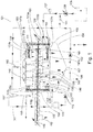
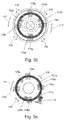
- Figure 1 , 2 and 3a +b illustrates a first embodiment of a separator 101, where figure 1 illustrates the separator, while figure 2 is a close-up of the rotating container 103 and figure 3a +b illustrates the first and second end of the separator 101.
- the separator 101 can separate for example 3.000 litres per hour of raw manure, i.e. animal waste slurry.
- the slurry is pumped from for example a feeding tank 105 in a flow-determined frequency-controlled manner 107 by means of an eccentric screw slurry pump 109 to a rotating container 103.
- the rotating container 103 is surrounded by a cover 155 which protects the rotating container 103.
- the bottom of the cover 154 is funnel-shaped for easier drainage of the filtrate from the cover 155.
- the rotating container 103 rotates and is driven by a toothed belt 111, or in other embodiments by a gear rim, connected to a frequency-controlled belt or gear drive motor 113 optionally with gears which is located next to the rotating container 103.
- asynchronous vibrating motors 115a,b,c,d,e,f,g,h are mounted at each end of the rotating container 103.
- the asynchronous vibrating motors 115a,b,c,d,e,f,g,h cause the rotating container 103 to perform forward and backward movements (for example + / - 6 mm) (see arrow 119 in fig. 3a +b) in the direction of rotation 117 of the rotating container 103.
- an alternative embodiment has an arrangement of two synchronous vibrating motors arranged symmetrically about the rotating containers rotating axis.
- more synchronous motors may be arranged on the container as long as they are arranged symmetrically with respect to the rotation axis.
- the rotating container 103 is mounted on a round H-section 121a,b at each end wall 123a,b. Rubber wheels 125a,b,c,d,e,f are mounted from the support (not shown) and run inside the H-section 121a,b. Where gear rims are used they may advantageously run on the outside. Outside the H-section 121a is the toothed belt mounted 111.
- the H-section 121a,b is at at least one side provided with a track (slipring) for providing the asynchronous vibrating motors 115a,b,c,d,e,f,g,h with electricity.
- the rotating container 103 is connected to the H-section 121a,b by means of vibration absorbers 127a,b,c,d,e,f,g,h (127c,d,g,h is not shown) such as rubber or steel springs to prevent oscillations from being transmitted from the rotating container 103 to the H-section 121a,b.
- the slurry is feeded into the rotating container 103 through a first inlet 129.
- a spiral vane 133 is provided along the inner surface of the side wall 131 of the rotating container 103.
- the rotation of the rotating container 103 directs the slurry from one end of the rotating container 103 to the other end under constant drainage, where a first filtrate exits the rotating container 103 through second openings 135 herein.
- a first retentate is transported by means of two lift paddles 137a,b into a funnel 139 and onto a feed screw 141. In this manner, the lift paddle 137a,b comes in contact with the funnel 139 which is part of the feed screw 141.
- the feed screw 141 is a perforated tube 140 allowing additional drainage of liquid from the first retentate during transportation.
- the first retentate is transported by the feed screw 141 into a screw press 145, where the first retentate is pressed/squeezed draining off a second filtrate 147 through holes 148 in the rotating container 103.
- the material is pressed against the transport screw 143 which provides resistance and a plug builds up, providing the block against which the pressure in the screw presses for squeezing the liquid out of the material.
- the torque in the axle of the feed screw and screw press builds up which may be measured in the motor 151.
- the transport screw 143 is activated, whereby the plug or at least part of the plug is removed and the torque lowered.
- the separation process of the first retentate into a second retentate and a second filtrate is adjusted by the motor driven 149 or retaining plate/cone of the transport screw 143.
- the transporting mechanism of the feed screw 141 and the screw press 145 is powered by a frequency controlled and torque registrating motor 151.
- the screw press 145 is arranged partly inside the rotating container 103 through a first opening 150 in the rotating container 103.
- a first outlet 152 is provided in the end of the transport screw 143 allowing retentate to exit the transport screw 143.
- the first and second filtrate is collected beneath the rotating container 103 in the cover (filtrate tank) 154.
- the filtrate can be recycled by means of the filtrate pump 153 through a hydrocyclone 157.
- small solids can be removed from the filtrate resulting in a third retentate 159 and a third filtrate 161.
- the third retentate can be directed to a separate collection or alternatively mixed with the first retentate at the feed screw 141.
- the level of filtrate in the rotating container 103 is measured using a direct analogue transmitter 163, for example ultrasound or radar to control the speed of pumping slurry into the rotating container 103. If the incoming flow of slurry increases above a defined setpoint, a first valve opens 165 and the rotating container 103 is washed down with filtrate obtained from the cover 154. The washing down process can be performed one or more times. If the level of filtrate is not reduced or if it increases to a higher setpoint, the washing down process changes to a cleaning process using acid or base using a CIP-procedure (Clean In Position).
- a CIP-procedure can be performed by using either an acid or a base.
- retentate is removed from the separator 101 by stopping the introduction of slurry into the rotating container 103 but maintaining the separation of the slurry already present in the rotating container 103 until all retentate has been removed from the rotating container 103.
- the feed screw 141, screw press 145 and transport screw 143 are stopped.
- a predetermined dose of acid is added to the filtrate from an acid tank 175.
- the rotating container 103 is then washed down with the acidified filtrate. The washing down can be performed one or more times.
- a third outlet 169 is opened whereby the filtrate is passed to a filtrate tank.
- the feeding of slurry to the rotating container 103 is stopped by stopping the pump 109, where after the filtrate pump 153 pumps filtrate for washing down the feeding tubes by opening a second valve 171.
- the feeding tubes are washed down from the feeding pump 109 to the rotating container 103. This prevents sedimentation of solids in the feeding tubes due to lack of flow in the tubes.
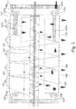
- Figure 4 and 5 illustrate a second embodiment of a separator 201, where the separator 201 includes a support 277 and a filtrate tank 255 as well as a pump 279 for pumping said filtrate.
- the rotating container 203 is connected to the support 277 enabling the rotating container 203 to rotate around an axis substantially parallel with the combined feed 241 and screw press 245.
- a first filtrate is drained through openings 235 of the rotating container 203 and - moved via the spiral vane 233 towards the lifting paddle 237 - where a first retentate is transported into the feed 241 and screw press 245 and further towards the transport screw 243.
- Perforations 240 around the feed screw part 241 allow further drainage of the first retentate during transportation towards the screw press part 245.
- Holes 248 in the screw press part 245 allow the second filtrate to be drained (inside the rotating container 203) from the first retentate leaving the second retentate in the screw press part 245, going further to the transport screw 243.
- the separator 201 is provided with a hydrocyclone 257 for further purification of at least the first and second filtrate.
Description
- The present invention relates to a separator for separating solids from a slurry and a method for separating solids from a slurry.
- Separation of particles from a liquid is desirable in many cases for example for recycling purposes or for more efficient handling or processing of the separated components. One example could be the removal of solids from animal slurries.
- Separation of solids from liquid is important for the use of animal waste slurries. Slurry can be used in biogas plants for obtaining energy. However, it is essential that the amount of dry matter in the slurry or the fraction of the slurry used in the biogas plant is as high as possible in order to be energetically feasible.
-
WO 96/30102 A1 -
US 6,227,379 describes a method and an apparatus for removal of solids from a slurry. The slurry is introduced into a rotating container. As the container rotates, lift paddles lift a portion of the slurry, allowing the liquid portion of the slurry to fall back into the slurry pool to be separated and lifting the solids towards the top of the container, where the solids by gravity slide into a collection tray for being transported out of the container. - The separation process as described in
US 6,227,379 separates solids from liquid matter by means of gravity alone. Therefore, the solid fraction still comprises a large amount of liquid, since a considerable amount of liquid will be retained by the fibres in the solid fraction. - It is the object of the present invention to obtain an improved method for separation of slurry, where the solids and the liquid portion of the slurry are more efficiently separated.
- This object is achieved by providing a separator according to claim 1 for separating solids from a slurry.
- By "slurry" is to be understood any kind of liquid comprising solids but preferably animal waste slurries and waste water. More preferably animal waste slurries and waste water having a particle size above 100 µm.
- By "filtrate" is to be understood what is drained from the slurry or from any of the retentates during the separation process. Filtrate can be a mixture of the first and second filtrate, the first, second and third filtrate, the first, second, third and fourth filtrate, etc.
- "At least a first filtrate" means that more than the first filtrate can be present, i.e. the first and second filtrate can be present, or the first, second and third filtrate can be present, etc.
- By "retentate" is to be understood what is left from the slurry when filtrate has been drained off. Retentate can be a mix of the first and second retentate, the first, second and third retentate, the first, second, third and fourth retentate, etc.
- The rotating container comprises a side wall and two end walls and is preferably cylindrically shaped. As an alternative embodiment, the container can have a cross-section substantially parallel to at least one of the end walls being a triangle, a square, a rectangle, a pentagon, a hexagon, etc.
- A cylinder has a basic curvilinear geometric shape, the surface of which is formed by the points at a fixed distance from a given line segment, the axis of the cylinder. The solid enclosed by this surface and by two planes perpendicular to the axis is also called a cylinder. In this manner, a cylinder may have any suitable cross-sectional shape perpendicular to its axis, such as circular, oval, triangular, rectangular, square, etc.
- The rotating container is connected to a support in a manner enabling the container to be able to rotate around an axis. In a preferred embodiment, the axis is defined by two connecting points where the rotating container is connected to the support.
In one embodiment, the rotating container rotates slowly for example 1-5 revolutions per min. - The rotating container can rotate either with a constant speed or rotate in intervals.
When the slurry is relatively fluid, the constant rotation speed allows the liquid fraction enough time to be separated from the more solid fraction, whereas for other slurries, rotation in intervals will allow the slurry to drain liquid before being agitated (by the rotation) into a new position where more liquid may be drained off etc. - The support can be arranged on the ground for supporting and carrying the rotating container. In one embodiment, at least a part of the support is an H-section.
- The rotating container comprises at least a first inlet. Through the first inlet the slurry is transported into the rotating container for separation. Each rotating container may comprise one, two, three or more first inlets. By having more first inlets the amount of slurry transported into the rotating container can be increased. Alternatively, slurry from different sources or feeding containers can be transported into the rotating container at one time.
- In a further advantageous embodiment, the separator further comprises a feeding tank; said feeding tank being fluidly connected with said rotating container via said first inlet. The feeding tank can be a storage tank for containing animal waste slurry which is normally present at most farms. Alternatively, the feeding tank can be a collection tank where to slurry is provided.
- The rotating container comprises at least a first opening. Through the first opening the solids obtained from the slurry is removed from the rotating container. Each rotating container may comprise one, two, three or more first openings. By having more first outlets the amount of solid transported from the rotating container can be increased.
- The rotating container comprises at least one second opening. Hereby is to be understood that one, two, three, four, five, six, etc. second openings are provided in the rotating container. In a preferred embodiment, a plurality of second openings is provided in the rotating container. The at least one second opening can be provided in the side wall or/and one or two of the end walls. In one embodiment, a plurality of second openings is provided in the side wall.
- The at least one second opening in the rotating container drains liquid in the form of a first filtrate from the slurry leaving solids in the form of a first retentate in the rotating container.
- In one embodiment, the size of the at least one second opening is equal to or below 40 µm.
- In one embodiment, said rotating container is provided with a filter cloth. The filter cloth can be an edge filter or a cross-woven filter. Providing the rotating container with a filter cloth increases the process of separation. Furthermore, minor particles can be separated from the liquid part of the slurry by using a filter cloth.
- A press screw placed in a tube forming a screw press, is provided at least partly into said first opening. The screw press presses (squeezes) the first retentate obtained from the slurry, whereby further liquid in the form of a second filtrate is removed from the first retentate. Hereby, the solid portion of the first retentate is increased leaving a second retentate.
- As an example, the amount of dry matter in animal waste slurry prior to separation is approximately 5%. Separation by means of the rotating container increases the amount of dry matter in the first retentate to approximately 15% while the following separation by means of the screw press increased the dry matter in the second retentate to approximately 30-40%.
- In order for the second filtrate to be removed from the screw press, the tube around the screw press is provided with at least one hole placed inside the rotating drum. Hereby is to be understood that the screw press can be provided with one, two, three, four, etc. holes in the tube. In one embodiment, the screw press is provided with a plurality of holes in the tube.
- The holes are provided on the part of the screw press arranged inside the rotating container. This is advantageous, since the second filtrate then automatically is drained from the rotating container due to the openings hereof in the same place where the first filtrate is drained. Thus, the first and second filtrates are mixed and can easily be collected in one batch. Furthermore, this saves energy in the process since no additional pumps are needed for transporting the second filtrate.
- In one embodiment, 1/3 to 1/2 of the length of the screw press is arranged inside the rotating container.
- In one embodiment, two or more screw presses are provided through two or more first openings.
- In one embodiment, the outer diameter of the screw press tube is 150 to 200 mm.
- In a further embodiment, the turns of the screw press are degressively decreasing from 150 to 90 mm rotating in the pressurizing part of the screw press having a slit of 0.5-2.0 mm.
- In one embodiment the screw press is operated by means of a counter pressure cone with a threaded rod.
- Alternatively to the above means, in order to retain the material and increase or maintain the pressure in the screw press, a counter pressure snail which transports second retentate from the screw press may be provided, where said counter pressure snail is regulated by the torque of the screw press, i.e. increasing torque initiates the counter pressure snail until the torque is back to normal. The counter pressure snail may advantageously be perpendicularly arranged with respect to the screw press.
- Alternatively, the retaining of material in the screw press is maintained by a spring regulated counter pressure cone, where speed of the screw press is controlled in order to maintain a constant torque.
- A feed screw part is provided inside the rotating container in front of the screw press. Hereby, is to be understood that the feed screw is connected with the screw press and that the feed screw is able to transport solids from the slurry in the form of the first retentate to the screw press for pressing of the first retentate. Alternatively, is to be understood that the screw press and feed screw is a combined mechanism (same axial drive screw) for transporting and pressing the first retentate.
- In one embodiment, the outer diameter of the feed screw tube is 150 to 200 mm.
- The first retentate is transported to the feed screw by means of at least one lift paddle. Hereby, is to be understood that one, two, three, four, five, six, etc. lift paddles can be arranged inside the rotating container.
- A first part of the at least one lift paddle is arranged along the inner surface of the side wall of the rotating container for being able to come into contact with the first retentate, which due to gravity is present at the lowest point of the inner surface of the side wall of the rotating container, the first retentate is lifted via said at least one lift paddle, when the rotating container rotates, and slides due to gravity onto the feed screw, since a second part of the at least one lift paddle is superposed the feed screw.
- In one embodiment, the first and the second part of the lift paddle is opposite of one another.
- The lift paddle can be of any shape which enables the first retentate to be effectively transported onto the feed screw. In one embodiment the free side of the paddle closest to the container's centreline is provided with a bend. In order to retain the lifted material long enough to ensure that as the paddle is tilted due to the rotation of the container, the material does not slide of the paddle until the paddle is superposed the funnel. The paddle may furthermore be made with a mesh structure whereby free liquid is allowed to drain off before the material enters the feed screw and screw press. The mesh structure will also provide more friction whereby the material will have less tendency to slide of the paddle, before the paddle is superposed the funnel.
- The feed screw is a tube; said tube being open at the part of the first feed screw being connected with said blade and said tube being at least in some part of the tube perforated allowing additional drainage of second filtrate from the first retentate.
- A funnel is a part of the feed screw and receives the first retentate transported by the lift paddle.
- In a further advantageous embodiment, said rotating container further comprises a spiral vane, said spiral vane is provided along said inner surface of said side wall of said rotating container.
- By use of the spiral vane the first retentate can be moved along the inner surface of the side wall of the rotating container. The purpose of the spiral vane is to move the first retentate towards the at least one lift paddle in order for all of the first retentate to be moved onto the feed screw. Thus, the direction of the feed screw is towards the at least one lift paddle.
- If the at least one lift paddle is not arranged next to one of the end walls, more spiral vanes are advantageously arranged in the rotating container for the first retentate to be transported towards the lift paddle from both sides.
- Alternatively, the rotating container can be arranged in an inclined angle in order for the first retentate to be transported towards the lift paddle by means of gravity.
- In a further advantageous embodiment, the rotating container further is provided with at least one asynchronous vibrating motor. Hereby, the rotating container is able to oscillate forwards and backwards with regard to the rotation of the rotating container. Thus, the filter cloth and/or the at least one second opening of the rotating container can be mechanically rinsed. Hence, the separation process is not interrupted by clotting of the filter cloth and/or the at least one opening.
- In one embodiment, the at least one asynchronous vibrating motor is provided at one of the end walls of the rotating container.
- In a further embodiment, the asynchronous vibrating motors are provided at the two end walls of the rotating container. The same number of asynchronous vibrating motors is provided on each of the end walls of the rotating container.
- In a further embodiment, four asynchronous vibrating motors are provided at each of the two end walls. Thus, the rotating container is provided with a total of eight asynchronous vibrating motors.
- In a further embodiment at least one synchronous vibrating motor is provided connected to the rotating container. It is particularly preferred to use two synchronous motors arranged symmetrically around the axis around which the feed screw and other implements are arranged and fastened to the end wall of the rotating container. By controlling the synchronous vibrations, it is possible to impart vibrations having a relatively large amplitude to the container, and thereby exert substantial impact on the materials inside the rotating container, resulting in an increase in the separation, both with respect to lessen the process time in the container and with respect to handle more material at improved separation.
- In a further embodiment, the rotating container is connected to the support by vibration absorbers. Hereby, the oscillations of the rotating container are not transmitted to the support. The vibration absorbers can for example be rubber or steel springs.
- In a further advantageous embodiment, said separator further comprises a cover; said cover surrounds said rotating container. Hereby, the filtrate separated from the slurry and transported out of the second openings of the rotating container is kept inside the cover and prevented from squirting from the rotating container.
- In a further embodiment, the cover is a moisture-proof envelope, whereby oxidation and dehydration of the surfaces of the separator is reduced. Hereby, the rate of formation as well as the amount of struvite is heavily reduced.
- In one embodiment, the cover is not rotating with the rotating container, but the rotating container rotates inside the cover.
- In a further embodiment, the asynchronous or synchronous vibrating motors are provided inside the cover.
- In a further advantageous embodiment, said separator further comprises a filtrate tank for collecting at least a filtrate; said filtrate tank being fluidly connected with said rotating container. Hereby, at least the filtrate can be collected, and it is prevented that at least the filtrate is just poured into the ground. Furthermore, the filtrate collected in the filtrate tank can be used for cleaning of the rotating container and pipes connecting for example the feeding tank and the rotating container as well as pipes connecting the filtrate tank and the rotating container.
- The fluid connection between the rotating container and the filtrate tank can be a funnel directing the filtrate into the filtrate tank. Alternatively, the filtrate may just drip into the filtrate tank from the rotating container.
- In a further embodiment, the fluid connection between the rotating container and the filtrate tank can be a pipe which is connected to the cover.
- In a further embodiment, the cover comprising a funnel-shaped part; said funnel-shaped part is fluidly connected to the filtrate tank. The funnel-shaped part of the cover is advantageously arranged at the bottom of the cover. Hereby, the filtrate is due to gravity transported to the funnel-shaped part and further into the filtrate tank. All of the filtrate is thus drained optimally from the cover.
- In a further embodiment, the cover comprises a closable outlet. Hereby, the transport of filtrate from the cover to the filtrate tank can be controlled.
- In a further advantageous embodiment, said filtrate tank is fluidly connected to a hydrocyclone. In a still further advantageous embodiment, a hydrocyclone is fluidly connected to the cover.
- A hydrocyclone is capable of separating very small solids from liquids and thus is able to separate small solids from the at least first filtrate resulting in a third retentate and a third filtrate. Hereby, a larger amount of solids can be purified from the slurry. The third retentate from the hydrocyclone contains elevated concentrations of phosphorous.
- In one embodiment, solids down to 8 µm can be separated from the filtrate by means of the hydrocyclone.
A hydrocyclone is a device to classify, separate or sort particles in a liquid suspension based on the ratio of their centripetal force to fluid resistance. A hydrocyclone will normally have a cylindrical section at the top, where liquid is being fed tangentially, and a conical base. The angle, and hence length of the conical section, plays a role in determining operating characteristics. - A hydrocyclone has two exits on the axis: the smaller on the bottom (underflow or reject) and a larger at the top (overflow or accept). The underflow is generally the denser or coarser fraction, while the overflow is the lighter or finer fraction.
- The third retentate from the hydrocyclone can be fed to the feed screw in order to be mixed with the first retentate through a second inlet. Hereby, larger solids in the first retentate will maintain the smaller solids from the third retentate. Alternatively, the third retentate can be collected separately.
- The third filtrate can be mixed with at least the first filtrate by transporting the third filtrate into the rotating container through a third inlet.
- Alternatively, the third filtrate can be mixed with at least the first filtrate by transporting the third filtrate into the cover through a third inlet.
- Alternatively, the third filtrate can be collected separately.
- In an advantageous embodiment, a material (mainly liquid) level transmitting mean is provided in said rotating container. The means for detecting/monitoring the level may for example be a radar or ultrasound device, but also mechanical means, such as a float on a detector arm may be used. Hereby, the functioning of the separator can be controlled since the level transmitting means is able to measure the level inside the rotating container and signal the result to other parts of the separator.
- In this manner, the flow of slurry pumped into the rotating container can be controlled and regulated in order for the flow to match the process of separation, i.e. if the level inside the rotating container is high it is an indication that the material, in particular the liquid fraction, does not leave the container fast enough. This in turn is an indication that the holes in the container wall and/or the filter cloth need to be cleaned or replaced.
- The level transmitting means in this manner helps to regulate the cleaning of the rotating container. A cleaning process can then automatically be started for removing the clotting of the rotating container or filter cloth by washing down the rotating container and the filter cloth by hosing using filtrate from either the filtrate tank or the cover. This process can be performed one or more times.
- This invention further describes a method for separating solids from slurry using a separator, said method being defined in claim 9.
- The slurry can be introduced into the rotating container at one of the ends or anywhere in between. Advantageously, the slurry is introduced in one of the ends in order to be transported along the entire length of the rotating container before being lifted to the feed screw. During the transportation along the rotating container the first filtrate is drained off the slurry, through at least one second opening in the rotating container and leaves a first retentate to be lifted onto the feed screw by means of lift paddles.
- The first retentate can be transported to the at least one lift paddle by means of gravity by arranging the separator in an inclined position. Alternatively, the first retentate is transported along the inside surface of said rotating container by means of a spiral vane.
- The feed screw part transport the first retentate under further drainage to the screw press part where the first retentate is pressed into a second retentate and a second filtrate, which retentate can be removed from the screw press and used as for example compost.
- Although the combined feed screw and screw press and the transport screw are arranged co-axially in the container, their axles are not necessarily connected. The feed screw moves material from the funnel into the screw press. Due to the increased lead of the screw press' blades the material will be compacted. This effect is achieved as the transport screw creates a plug (either because it does not rotate or rotates substantially slower), whereby the material inside the press screw is compacted and the liquid fraction / second filtrate escapes through holes in the tube surrounding the screw press. When the torque on the axle of the screw press achieves a certain level the transport screw is activated removing at least a part of the plug, thereby relieving part of the pressure whereby new material can enter the screw press. The transport screw in this manner determines the pressure in the screw press (which is detected and measured as torque on the screw press axle). The transport screw may rotate constantly, albeit at different speeds in response to the torque on the screw press axle, or may operate intermittently, i.e. rotate from time to time in order to remove (part of) the plug.
- The first filtrate and the second filtrate are collected, preferably in the same batch.
- Furthermore, the method comprises the steps of separating the first and second filtrate further into a third retentate and a third filtrate by means of a hydrocyclone and optionally mixing said third filtrate with said first and second filtrate and/or optionally mix-ing said third retentate with said first retentate.
- In a further embodiment, the filtrate in the filtrate tank is recycled several times over the hydrocyclone. As an example, the filtrate can be recycled three times per batch of slurry separated. For each process of recycling a further retentate and filtrate is obtained, i.e. after a second time over the hydrocyclone a fourth retentate and a fourth filtrate is obtained, after a third time over the hydrocyclone a fifth retentate and a fifth filtrate is obtained, and so forth.
- As an example, 50% of solids above 8µm can be removed by each passing. If the filtrate is recycled for example 3-4 times this means that 90% of the small solids are removed.
- When separating animal slurry, up to 60% of the phosphorous present in the slurry is maintained in the retentate after 3-4 recycles. Thus, the third filtrate is heavily reduced of phosphorous and can be used for distribution of manure in environmentally sensitive areas.
- Furthermore, the method comprises a cleaning procedure, where said rotating container is rinsed by the following steps:
- a) removing said first, second and optionally said third retentate from said rotating container;
- b) adding an acid or a base to said first, second and optionally said third filtrate obtaining a cleaning liquid;
- c) rinsing said rotating container at least one time with said cleaning liquid.
- A CIP-procedure can be performed by using an acid. Before the procedure starts, retentate is removed from the separator by stopping the flow of slurry into the rotating container but maintaining the separation process for a while until all retentate has been removed from the rotating container. Then, a predetermined dose of acid is added to the filtrate present either in the cover or in a filtrate tank from an acid tank. Then, the rotating container is then washed down with the acidified filtrate. The washing down can be performed one or more times.
- In a further embodiment, an additional CIP-pump can be provided together with a base tank for dosing a base to the filtrate. Hereby, the rotating container can be cleaned with both acid and/or base depending on the slurry to be separated.
-
- Fig. 1
- illustrates a first embodiment of a separator;
- Fig. 2
- illustrates a rotating container of a first embodiment of a separator;
- Fig. 3a
- illustrates a first end of a first embodiment of a separator;
- Fig. 3b
- illustrates a second end of a first embodiment of a separator;
- Fig. 4
- illustrates a three-dimensional view of a second embodiment of a separator;
- Fig. 5
- illustrates a cross-sectional view of a second embodiment of a separator.
-
Figure 1 ,2 and3a +b illustrates a first embodiment of aseparator 101, wherefigure 1 illustrates the separator, whilefigure 2 is a close-up of therotating container 103 andfigure 3a +b illustrates the first and second end of theseparator 101. Overall, theseparator 101 can separate for example 3.000 litres per hour of raw manure, i.e. animal waste slurry. The slurry is pumped from for example afeeding tank 105 in a flow-determined frequency-controlledmanner 107 by means of an eccentricscrew slurry pump 109 to arotating container 103. - The
rotating container 103 is surrounded by acover 155 which protects therotating container 103. The bottom of thecover 154 is funnel-shaped for easier drainage of the filtrate from thecover 155. - The
rotating container 103 rotates and is driven by atoothed belt 111, or in other embodiments by a gear rim, connected to a frequency-controlled belt orgear drive motor 113 optionally with gears which is located next to therotating container 103. - Eight asynchronous vibrating
motors 115a,b,c,d,e,f,g,h are mounted at each end of therotating container 103. The asynchronous vibratingmotors 115a,b,c,d,e,f,g,h cause therotating container 103 to perform forward and backward movements (for example + / - 6 mm) (seearrow 119 infig. 3a +b) in the direction ofrotation 117 of therotating container 103. This gives the same advantages as improved mechanical cleaning of the filter cloth, as in a traditional horizontal vibration sieve. - Although not illustrated an alternative embodiment has an arrangement of two synchronous vibrating motors arranged symmetrically about the rotating containers rotating axis. Naturally, more synchronous motors may be arranged on the container as long as they are arranged symmetrically with respect to the rotation axis.
- The
rotating container 103 is mounted on a round H-section 121a,b at eachend wall 123a,b.Rubber wheels 125a,b,c,d,e,f are mounted from the support (not shown) and run inside the H-section 121a,b. Where gear rims are used they may advantageously run on the outside. Outside the H-section 121a is the toothed belt mounted 111. - The H-
section 121a,b is at at least one side provided with a track (slipring) for providing the asynchronous vibratingmotors 115a,b,c,d,e,f,g,h with electricity. - The
rotating container 103 is connected to the H-section 121a,b by means ofvibration absorbers 127a,b,c,d,e,f,g,h (127c,d,g,h is not shown) such as rubber or steel springs to prevent oscillations from being transmitted from therotating container 103 to the H-section 121a,b. - The slurry is feeded into the
rotating container 103 through afirst inlet 129. Along the inner surface of theside wall 131 of therotating container 103, aspiral vane 133 is provided. Hereby, the rotation of therotating container 103 directs the slurry from one end of therotating container 103 to the other end under constant drainage, where a first filtrate exits therotating container 103 throughsecond openings 135 herein. At the other end of therotating container 103, a first retentate is transported by means of twolift paddles 137a,b into afunnel 139 and onto afeed screw 141. In this manner, thelift paddle 137a,b comes in contact with thefunnel 139 which is part of thefeed screw 141. Thefeed screw 141 is aperforated tube 140 allowing additional drainage of liquid from the first retentate during transportation. - The first retentate is transported by the
feed screw 141 into ascrew press 145, where the first retentate is pressed/squeezed draining off asecond filtrate 147 throughholes 148 in therotating container 103. During this press action, the material is pressed against thetransport screw 143 which provides resistance and a plug builds up, providing the block against which the pressure in the screw presses for squeezing the liquid out of the material. As pressure builds up in the screw press, the torque in the axle of the feed screw and screw press builds up which may be measured in themotor 151. At a certain torque level, thetransport screw 143 is activated, whereby the plug or at least part of the plug is removed and the torque lowered. - The separation process of the first retentate into a second retentate and a second filtrate is adjusted by the motor driven 149 or retaining plate/cone of the
transport screw 143. The transporting mechanism of thefeed screw 141 and thescrew press 145 is powered by a frequency controlled andtorque registrating motor 151. - The
screw press 145 is arranged partly inside therotating container 103 through afirst opening 150 in therotating container 103. Afirst outlet 152 is provided in the end of thetransport screw 143 allowing retentate to exit thetransport screw 143. - The first and second filtrate is collected beneath the
rotating container 103 in the cover (filtrate tank) 154. The filtrate can be recycled by means of thefiltrate pump 153 through ahydrocyclone 157. In thehydrocyclone 157 small solids can be removed from the filtrate resulting in athird retentate 159 and a third filtrate 161. The third retentate can be directed to a separate collection or alternatively mixed with the first retentate at thefeed screw 141. - The level of filtrate in the
rotating container 103 is measured using a direct analogue transmitter 163, for example ultrasound or radar to control the speed of pumping slurry into therotating container 103. If the incoming flow of slurry increases above a defined setpoint, a first valve opens 165 and therotating container 103 is washed down with filtrate obtained from thecover 154. The washing down process can be performed one or more times. If the level of filtrate is not reduced or if it increases to a higher setpoint, the washing down process changes to a cleaning process using acid or base using a CIP-procedure (Clean In Position). - A CIP-procedure can be performed by using either an acid or a base. Before the procedure starts, retentate is removed from the
separator 101 by stopping the introduction of slurry into therotating container 103 but maintaining the separation of the slurry already present in therotating container 103 until all retentate has been removed from therotating container 103. Hereafter, thefeed screw 141,screw press 145 andtransport screw 143 are stopped. By means of the CIP-pump 173, a predetermined dose of acid is added to the filtrate from anacid tank 175. Therotating container 103 is then washed down with the acidified filtrate. The washing down can be performed one or more times. - When the level of filtrate in the
cover 154 exceeds a given setpoint as measured by alevel transmitter 167, athird outlet 169 is opened whereby the filtrate is passed to a filtrate tank. - By breakdown of the separation process, the feeding of slurry to the
rotating container 103 is stopped by stopping thepump 109, where after thefiltrate pump 153 pumps filtrate for washing down the feeding tubes by opening asecond valve 171. The feeding tubes are washed down from thefeeding pump 109 to therotating container 103. This prevents sedimentation of solids in the feeding tubes due to lack of flow in the tubes. - In
figure 1 andfigure 2 , the arrows illustrate the flow of the slurry, the retentates, the filtrates and the acid. -
Figure 4 and5 illustrate a second embodiment of aseparator 201, where theseparator 201 includes asupport 277 and afiltrate tank 255 as well as apump 279 for pumping said filtrate. - The
rotating container 203 is connected to thesupport 277 enabling therotating container 203 to rotate around an axis substantially parallel with the combinedfeed 241 andscrew press 245. During rotation, a first filtrate is drained throughopenings 235 of therotating container 203 and - moved via thespiral vane 233 towards the lifting paddle 237 - where a first retentate is transported into thefeed 241 andscrew press 245 and further towards thetransport screw 243.Perforations 240 around thefeed screw part 241 allow further drainage of the first retentate during transportation towards thescrew press part 245.Holes 248 in thescrew press part 245 allow the second filtrate to be drained (inside the rotating container 203) from the first retentate leaving the second retentate in thescrew press part 245, going further to thetransport screw 243. - Furthermore, the
separator 201 is provided with ahydrocyclone 257 for further purification of at least the first and second filtrate.
Claims (11)
- A separator for separating solids from a slurry comprising- a rotating container (103, 203) comprising a side wall (131) and two end walls (123a, 123b) where said rotating container (103, 203) is arranged on a support; where said rotating container (103, 203) is rotatably connected to said support;- said rotating container is provided with at least a first inlet (129) for the slurry and at least a first opening (150);- said rotating container (103, 203) comprises at least one second opening (135) for a first filtrate;- a feed and screw press (141,241,145,245) being provided inside said rotating container (103, 203), wherein said feed and screw press comprises a tube (140) in which in the direction of the flow a feed screw and then a press screw are located and wherein said tube comprises around said press screw at least one hole (148, 248), wherein said feed and screw press comprises a funnel (139) on said tube for receiving a first retentate for feeding said feed screw, wherein the first retentate is transported by the feed screw into the screw press, where said first retentate is pressed to produce a second retentate and draining off a second filtrate through said at least one hole (148, 248) into said rotating container;- at least one lift paddle (137a, 137b, 237) being provided inside said rotating container (103, 203) where a first part of said lift paddle is arranged along an inner surface of said side wall (131) of said rotating container (103, 203) so that during rotation of the rotating container the first retentate is lifted via said at least one lift paddle and slides into said funnel (139) due to gravity,- a transport screw (143, 243) is arranged through said first opening (150) of said rotating container, coaxially with and downstream to said press screw (145, 245), wherein a first outlet (152) is provided at the end of said transport screw for discharging said second retentate, wherein said transport screw (143) is capable of rotating independently of said feed and press screws and can be controlled independently from said feed and screw press.
- The separator according to claim 1, characterised in that said rotating container (103, 203), further comprises a spiral vane (133, 233), said spiral vane is provided along said inner surface of said side wall (131) of said rotating container (103, 203).
- The separator according to any of the preceding claims, characterised in that said rotating container (103, 203) further is provided with at least one asynchronous vibrating motor (115a-115h).
- The separator according to claim 1 or 2, characterised in that said rotating container (103, 203) further is provided with at least one synchronous vibrating motor.
- The separator according to any of the preceding claims, characterised in that said separator further comprises a cover (154, 254); said cover surrounds said rotating container (103, 203).
- The separator according to any of the preceding claims, characterised in that said separator further comprises a filtrate tank (155,255) for collecting said first filtrate and said second filtrate; said filtrate tank (155,255) being fluidly connected with said rotating container (103, 203).
- The separator according to any of the claims 5-6, characterised in that said filtrate tank (155,255) is fluidly connected downstream to a hydrocyclone (157, 257).
- The separator according to any of the preceding claims, characterised in that a pressure/level transmitting means (163) is provided in said rotating container (103, 203).
- A method for separating solids from slurry using a separator as described in any of the claims 1-7 comprising the following steps:a) introducing a slurry through a first inlet (129) into a rotating container (103, 203);b) separating a first filtrate from a first retentate by means of said at least one second opening being (135) provided in said rotating container (103, 203) allowing said filtrate to escape the container (103, 203) and by rotating said rotating container (103, 203) around a rotation axis and transporting said first retentate along the inside surface (131) of the rotating container (103, 203) to at least one lift paddle (137a, 137b, 237);c) collecting said first filtrate;d) transporting said first retentate onto a feed screw (141, 241) by means of said at least one lift paddle (137a, 137b, 237);e) transporting said first retentate by means of said feed screw part (141, 241) to a screw press part (145, 245);f) pressing said first retentate by means of said screw press part (145, 245) allowing a second filtrate to escape resulting in a second retentate and a second filtrate;g) collecting said second filtrate with said first filtrate inside the rotating container (103, 203);h) removing said second retentate from said screw press part (145, 245) with the transport screw (143,243).
- The method according to claim 9, where said first and second filtrates are further separated into a third retentate and a third filtrate by means of a hydrocyclone (157, 257) and optionally mixing said third filtrate with said first and second filtrate and/or optionally mixing said third retentate with said first retentate.
- The method according to any of the claims 9 or 10, where said rotating container (103, 203) is rinsed by the following steps:a) removing said first, second and optionally said third retentate from said rotating container;b) adding an acid or a base to said first, second and optionally said third filtrate obtaining a cleaning liquid;c) rinsing said rotating container at least one time with said cleaning liquid.
Applications Claiming Priority (2)
| Application Number | Priority Date | Filing Date | Title |
|---|---|---|---|
| DKPA201270121 | 2012-03-19 | ||
| PCT/DK2013/050077 WO2013139343A1 (en) | 2012-03-19 | 2013-03-19 | Rotating separator |
Publications (2)
| Publication Number | Publication Date |
|---|---|
| EP2827964A1 EP2827964A1 (en) | 2015-01-28 |
| EP2827964B1 true EP2827964B1 (en) | 2019-10-23 |
Family
ID=48095482
Family Applications (1)
| Application Number | Title | Priority Date | Filing Date |
|---|---|---|---|
| EP13716187.3A Active EP2827964B1 (en) | 2012-03-19 | 2013-03-19 | Rotating separator |
Country Status (7)
| Country | Link |
|---|---|
| US (1) | US9358484B2 (en) |
| EP (1) | EP2827964B1 (en) |
| KR (1) | KR102160835B1 (en) |
| CN (1) | CN104470614B (en) |
| CA (1) | CA2867369A1 (en) |
| MX (1) | MX350577B (en) |
| WO (1) | WO2013139343A1 (en) |
Families Citing this family (26)
| Publication number | Priority date | Publication date | Assignee | Title |
|---|---|---|---|---|
| CA2847986A1 (en) * | 2011-09-06 | 2013-03-14 | Anaeco Limited | Separation method and apparatus |
| US9782703B2 (en) * | 2011-09-30 | 2017-10-10 | Basf Se | Device for separating a heterogeneous mixture of matter and method for cleaning a filter unit |
| CN104470614B (en) * | 2012-03-19 | 2017-04-19 | 丹麦纯滤有限责任公司 | Rotating separator |
| US20150008193A1 (en) * | 2013-07-05 | 2015-01-08 | Daritech, Inc. | Systems and Methods for Extracting Particulate from Raw Slurry Material |
| CA2917488C (en) * | 2013-07-26 | 2018-03-13 | Ishigaki Company Limited | Sludge dehydration system and sludge dehydration method |
| WO2015117007A1 (en) * | 2014-01-31 | 2015-08-06 | Dsm Ip Assets B.V. | Adipose tissue centrifuge and method of use |
| US10286340B2 (en) | 2014-05-27 | 2019-05-14 | Daritech, Inc. | Feed systems and methods for rotary screen separators |
| CA2893311A1 (en) | 2014-05-30 | 2015-11-30 | Daritech, Inc. | Cleaning systems and methods for rotary screen separators |
| US10603675B2 (en) | 2014-11-02 | 2020-03-31 | Dari-Tech, Inc. | Systems and methods for extracting particulate from raw slurry material |
| WO2016202911A1 (en) * | 2015-06-19 | 2016-12-22 | Serptec Gmbh | Screw press device |
| WO2017172980A1 (en) * | 2016-03-29 | 2017-10-05 | Valerio Thomas A | Use of multi-gravity separation to recover metals from iba, asr, and electronic scrap |
| CN105817069A (en) * | 2016-05-31 | 2016-08-03 | 上海迈正环境科技有限公司 | Kitchen waste dehydration and residue removal device |
| CN106039805A (en) * | 2016-07-10 | 2016-10-26 | 娄菊叶 | Novel sewage treatment system |
| US10967300B2 (en) * | 2017-08-29 | 2021-04-06 | Green Flow Industries, LLC | Transportable separation and monitoring apparatus with auger |
| CN107745536A (en) * | 2017-12-16 | 2018-03-02 | 李炫颖 | A kind of vertical helical screen cloth dewaterer |
| US11679348B2 (en) * | 2017-12-29 | 2023-06-20 | Enercorp Engineered Solutions Inc. | Horizontal sand separator assembly |
| GB2586200A (en) * | 2019-04-25 | 2021-02-17 | Sem Energy Ltd | Apparatus and method |
| JP7305762B2 (en) * | 2018-10-31 | 2023-07-10 | プロセス・ウェイストウォーター・テクノロジーズ,エルエルシー | adjustable container |
| CN109647040A (en) * | 2019-01-15 | 2019-04-19 | 浙江杭机股份有限公司 | A kind of filter device |
| EP3772382A1 (en) * | 2019-08-05 | 2021-02-10 | A O Ideas GmbH | Compacting device using ultrasonic vibrations |
| KR102504657B1 (en) * | 2019-11-18 | 2023-02-27 | 주식회사 엘지화학 | Pressurizing centrifugal dehydrator |
| SE544566C2 (en) * | 2020-01-31 | 2022-07-19 | Hydria Water Ab | A separation device and method to separate contaminants from contaminated water |
| CN112275404B (en) * | 2020-10-20 | 2022-01-07 | 重庆禀源环保科技有限公司 | Watershed water pollutant collecting and detecting equipment based on hydraulic engineering |
| CN112426787B (en) * | 2020-11-02 | 2021-12-31 | 深圳市树立水处理设备有限公司 | Microfiltration machine for solid-liquid separation |
| CN112999753B (en) * | 2021-02-25 | 2022-06-03 | 江西省科学院能源研究所 | Solid-liquid separation type energy-saving environment-friendly water treatment equipment |
| CN115708978A (en) * | 2022-12-20 | 2023-02-24 | 山东玲珑轮胎股份有限公司 | Reliable lubricating oil product filtering equipment for tire production |
Family Cites Families (14)
| Publication number | Priority date | Publication date | Assignee | Title |
|---|---|---|---|---|
| GB886015A (en) | 1957-03-19 | 1962-01-03 | Rose Downs & Thompson Ltd | An improved screw press |
| GB874594A (en) | 1959-02-20 | 1961-08-10 | Hartleys Stoke On Trent Ltd | Improvements in and relating to rotary drum screens |
| SU1386242A1 (en) | 1986-05-05 | 1988-04-07 | Всесоюзный Проектно-Технологический Институт По Электробытовым Машинам И Приборам | Drum filter for treatment of sediments of waste water |
| JP2512684B2 (en) | 1993-06-16 | 1996-07-03 | 日立造船株式会社 | Screw type dehydrator |
| CA2107172A1 (en) | 1993-09-28 | 1995-03-29 | Gunther Abel | Compactors |
| US6227379B1 (en) | 1994-12-14 | 2001-05-08 | Nth, Inc. | Rotary separator apparatus and method |
| SE504046C2 (en) | 1995-03-27 | 1996-10-28 | Roto Sieve Ab | dewatering |
| DE19514596A1 (en) | 1995-04-20 | 1996-10-24 | Huber Hans Gmbh Maschinen Und | Separator removing material from fluid feed has rotating, perforated separation drum |
| US6395187B1 (en) | 1998-10-01 | 2002-05-28 | Noe Martinez Alanis | Horizontal solids recycler |
| JP3775232B2 (en) | 2001-03-21 | 2006-05-17 | 株式会社石垣 | Screw press with concentration function |
| DE10316173B4 (en) | 2003-04-04 | 2006-03-16 | Hans Huber Ag Maschinen- Und Anlagenbau | Device for removing fine screenings from a liquid |
| KR100732984B1 (en) * | 2007-02-16 | 2007-06-28 | 김운섭 | A screw press type filter for wastewater treatment |
| MY153497A (en) * | 2009-03-19 | 2015-02-27 | Ishigaki Mech Ind | Concentrator-integrated screw press |
| CN104470614B (en) * | 2012-03-19 | 2017-04-19 | 丹麦纯滤有限责任公司 | Rotating separator |
-
2013
- 2013-03-19 CN CN201380014528.8A patent/CN104470614B/en not_active Expired - Fee Related
- 2013-03-19 CA CA2867369A patent/CA2867369A1/en not_active Abandoned
- 2013-03-19 WO PCT/DK2013/050077 patent/WO2013139343A1/en active Application Filing
- 2013-03-19 EP EP13716187.3A patent/EP2827964B1/en active Active
- 2013-03-19 MX MX2014011124A patent/MX350577B/en active IP Right Grant
- 2013-03-19 US US14/386,417 patent/US9358484B2/en active Active
- 2013-03-19 KR KR1020147029152A patent/KR102160835B1/en active IP Right Grant
Non-Patent Citations (1)
| Title |
|---|
| None * |
Also Published As
| Publication number | Publication date |
|---|---|
| CN104470614B (en) | 2017-04-19 |
| KR102160835B1 (en) | 2020-10-15 |
| US20150076084A1 (en) | 2015-03-19 |
| CN104470614A (en) | 2015-03-25 |
| EP2827964A1 (en) | 2015-01-28 |
| WO2013139343A1 (en) | 2013-09-26 |
| MX350577B (en) | 2017-09-11 |
| CA2867369A1 (en) | 2013-09-26 |
| MX2014011124A (en) | 2015-09-25 |
| US9358484B2 (en) | 2016-06-07 |
| KR20150003742A (en) | 2015-01-09 |
Similar Documents
| Publication | Publication Date | Title |
|---|---|---|
| EP2827964B1 (en) | Rotating separator | |
| JP5277152B2 (en) | High alkali slurry processing method and system | |
| KR101729262B1 (en) | Adulteration disposal equipment with wedge bar screen | |
| JP2011005362A (en) | Slurry treatment apparatus | |
| CN207546768U (en) | A kind of Efficient centrifugal ore separator for handling sludge | |
| CN107983526B (en) | Grading treatment process of silicon carbide micro powder | |
| CA3153193C (en) | Flocculation grading dehydration device | |
| CN109174612A (en) | A kind of concrete sandstone separator | |
| EP2628519A1 (en) | Device for removing liquid | |
| CN111187709B (en) | Desanding and homogenizing device and process suitable for anaerobic fermentation slurry | |
| CN211069150U (en) | Solid-liquid separation settling device | |
| KR101437908B1 (en) | Vertical type screw dehydrator | |
| CN212833084U (en) | A high-efficient separation and purification multiple-layer filtering device for bio-pharmaceuticals | |
| CN212018210U (en) | Food production wastewater treatment centrifuge | |
| US20080272047A1 (en) | Separating Device | |
| KR101192856B1 (en) | solid waste treatment apparatus | |
| CN105665108A (en) | Efficient pulping device | |
| CN217747280U (en) | High-efficient sesame grinding device | |
| EP2813272B1 (en) | Facility for screening an effluent loaded with suspended matter | |
| CN219816654U (en) | Three-phase horizontal decanter centrifuge | |
| CN218808675U (en) | Conveying equipment for reamer with accumulated materials on belt | |
| CN213835007U (en) | Dry oil sludge treatment device | |
| CN214556180U (en) | Kitchen waste treatment equipment | |
| CN208494506U (en) | A kind of eggshell egg liquid separating and reclaiming device | |
| RU2374399C1 (en) | Device for water cleaning from debris |
Legal Events
| Date | Code | Title | Description |
|---|---|---|---|
| PUAI | Public reference made under article 153(3) epc to a published international application that has entered the european phase |
Free format text: ORIGINAL CODE: 0009012 |
|
| 17P | Request for examination filed |
Effective date: 20141016 |
|
| AK | Designated contracting states |
Kind code of ref document: A1 Designated state(s): AL AT BE BG CH CY CZ DE DK EE ES FI FR GB GR HR HU IE IS IT LI LT LU LV MC MK MT NL NO PL PT RO RS SE SI SK SM TR |
|
| AX | Request for extension of the european patent |
Extension state: BA ME |
|
| STAA | Information on the status of an ep patent application or granted ep patent |
Free format text: STATUS: EXAMINATION IS IN PROGRESS |
|
| 17Q | First examination report despatched |
Effective date: 20170215 |
|
| GRAP | Despatch of communication of intention to grant a patent |
Free format text: ORIGINAL CODE: EPIDOSNIGR1 |
|
| STAA | Information on the status of an ep patent application or granted ep patent |
Free format text: STATUS: GRANT OF PATENT IS INTENDED |
|
| INTG | Intention to grant announced |
Effective date: 20190103 |
|
| GRAS | Grant fee paid |
Free format text: ORIGINAL CODE: EPIDOSNIGR3 |
|
| GRAA | (expected) grant |
Free format text: ORIGINAL CODE: 0009210 |
|
| STAA | Information on the status of an ep patent application or granted ep patent |
Free format text: STATUS: THE PATENT HAS BEEN GRANTED |
|
| AK | Designated contracting states |
Kind code of ref document: B1 Designated state(s): AL AT BE BG CH CY CZ DE DK EE ES FI FR GB GR HR HU IE IS IT LI LT LU LV MC MK MT NL NO PL PT RO RS SE SI SK SM TR |
|
| AX | Request for extension of the european patent |
Extension state: BA ME |
|
| REG | Reference to a national code |
Ref country code: GB Ref legal event code: FG4D |
|
| REG | Reference to a national code |
Ref country code: CH Ref legal event code: EP |
|
| REG | Reference to a national code |
Ref country code: IE Ref legal event code: FG4D |
|
| REG | Reference to a national code |
Ref country code: DE Ref legal event code: R096 Ref document number: 602013061963 Country of ref document: DE |
|
| REG | Reference to a national code |
Ref country code: AT Ref legal event code: REF Ref document number: 1193043 Country of ref document: AT Kind code of ref document: T Effective date: 20191115 |
|
| REG | Reference to a national code |
Ref country code: NL Ref legal event code: MP Effective date: 20191023 |
|
| REG | Reference to a national code |
Ref country code: LT Ref legal event code: MG4D |
|
| PG25 | Lapsed in a contracting state [announced via postgrant information from national office to epo] |
Ref country code: ES Free format text: LAPSE BECAUSE OF FAILURE TO SUBMIT A TRANSLATION OF THE DESCRIPTION OR TO PAY THE FEE WITHIN THE PRESCRIBED TIME-LIMIT Effective date: 20191023 Ref country code: PT Free format text: LAPSE BECAUSE OF FAILURE TO SUBMIT A TRANSLATION OF THE DESCRIPTION OR TO PAY THE FEE WITHIN THE PRESCRIBED TIME-LIMIT Effective date: 20200224 Ref country code: LT Free format text: LAPSE BECAUSE OF FAILURE TO SUBMIT A TRANSLATION OF THE DESCRIPTION OR TO PAY THE FEE WITHIN THE PRESCRIBED TIME-LIMIT Effective date: 20191023 Ref country code: GR Free format text: LAPSE BECAUSE OF FAILURE TO SUBMIT A TRANSLATION OF THE DESCRIPTION OR TO PAY THE FEE WITHIN THE PRESCRIBED TIME-LIMIT Effective date: 20200124 Ref country code: BG Free format text: LAPSE BECAUSE OF FAILURE TO SUBMIT A TRANSLATION OF THE DESCRIPTION OR TO PAY THE FEE WITHIN THE PRESCRIBED TIME-LIMIT Effective date: 20200123 Ref country code: NL Free format text: LAPSE BECAUSE OF FAILURE TO SUBMIT A TRANSLATION OF THE DESCRIPTION OR TO PAY THE FEE WITHIN THE PRESCRIBED TIME-LIMIT Effective date: 20191023 Ref country code: FI Free format text: LAPSE BECAUSE OF FAILURE TO SUBMIT A TRANSLATION OF THE DESCRIPTION OR TO PAY THE FEE WITHIN THE PRESCRIBED TIME-LIMIT Effective date: 20191023 Ref country code: SE Free format text: LAPSE BECAUSE OF FAILURE TO SUBMIT A TRANSLATION OF THE DESCRIPTION OR TO PAY THE FEE WITHIN THE PRESCRIBED TIME-LIMIT Effective date: 20191023 Ref country code: LV Free format text: LAPSE BECAUSE OF FAILURE TO SUBMIT A TRANSLATION OF THE DESCRIPTION OR TO PAY THE FEE WITHIN THE PRESCRIBED TIME-LIMIT Effective date: 20191023 Ref country code: NO Free format text: LAPSE BECAUSE OF FAILURE TO SUBMIT A TRANSLATION OF THE DESCRIPTION OR TO PAY THE FEE WITHIN THE PRESCRIBED TIME-LIMIT Effective date: 20200123 Ref country code: PL Free format text: LAPSE BECAUSE OF FAILURE TO SUBMIT A TRANSLATION OF THE DESCRIPTION OR TO PAY THE FEE WITHIN THE PRESCRIBED TIME-LIMIT Effective date: 20191023 |
|
| PG25 | Lapsed in a contracting state [announced via postgrant information from national office to epo] |
Ref country code: RS Free format text: LAPSE BECAUSE OF FAILURE TO SUBMIT A TRANSLATION OF THE DESCRIPTION OR TO PAY THE FEE WITHIN THE PRESCRIBED TIME-LIMIT Effective date: 20191023 Ref country code: IS Free format text: LAPSE BECAUSE OF FAILURE TO SUBMIT A TRANSLATION OF THE DESCRIPTION OR TO PAY THE FEE WITHIN THE PRESCRIBED TIME-LIMIT Effective date: 20200224 Ref country code: HR Free format text: LAPSE BECAUSE OF FAILURE TO SUBMIT A TRANSLATION OF THE DESCRIPTION OR TO PAY THE FEE WITHIN THE PRESCRIBED TIME-LIMIT Effective date: 20191023 |
|
| PG25 | Lapsed in a contracting state [announced via postgrant information from national office to epo] |
Ref country code: AL Free format text: LAPSE BECAUSE OF FAILURE TO SUBMIT A TRANSLATION OF THE DESCRIPTION OR TO PAY THE FEE WITHIN THE PRESCRIBED TIME-LIMIT Effective date: 20191023 |
|
| REG | Reference to a national code |
Ref country code: DE Ref legal event code: R097 Ref document number: 602013061963 Country of ref document: DE |
|
| PG2D | Information on lapse in contracting state deleted |
Ref country code: IS |
|
| PG25 | Lapsed in a contracting state [announced via postgrant information from national office to epo] |
Ref country code: EE Free format text: LAPSE BECAUSE OF FAILURE TO SUBMIT A TRANSLATION OF THE DESCRIPTION OR TO PAY THE FEE WITHIN THE PRESCRIBED TIME-LIMIT Effective date: 20191023 Ref country code: RO Free format text: LAPSE BECAUSE OF FAILURE TO SUBMIT A TRANSLATION OF THE DESCRIPTION OR TO PAY THE FEE WITHIN THE PRESCRIBED TIME-LIMIT Effective date: 20191023 Ref country code: CZ Free format text: LAPSE BECAUSE OF FAILURE TO SUBMIT A TRANSLATION OF THE DESCRIPTION OR TO PAY THE FEE WITHIN THE PRESCRIBED TIME-LIMIT Effective date: 20191023 Ref country code: DK Free format text: LAPSE BECAUSE OF FAILURE TO SUBMIT A TRANSLATION OF THE DESCRIPTION OR TO PAY THE FEE WITHIN THE PRESCRIBED TIME-LIMIT Effective date: 20191023 Ref country code: IS Free format text: LAPSE BECAUSE OF FAILURE TO SUBMIT A TRANSLATION OF THE DESCRIPTION OR TO PAY THE FEE WITHIN THE PRESCRIBED TIME-LIMIT Effective date: 20200223 |
|
| REG | Reference to a national code |
Ref country code: AT Ref legal event code: MK05 Ref document number: 1193043 Country of ref document: AT Kind code of ref document: T Effective date: 20191023 |
|
| PLBE | No opposition filed within time limit |
Free format text: ORIGINAL CODE: 0009261 |
|
| STAA | Information on the status of an ep patent application or granted ep patent |
Free format text: STATUS: NO OPPOSITION FILED WITHIN TIME LIMIT |
|
| PG25 | Lapsed in a contracting state [announced via postgrant information from national office to epo] |
Ref country code: SM Free format text: LAPSE BECAUSE OF FAILURE TO SUBMIT A TRANSLATION OF THE DESCRIPTION OR TO PAY THE FEE WITHIN THE PRESCRIBED TIME-LIMIT Effective date: 20191023 Ref country code: SK Free format text: LAPSE BECAUSE OF FAILURE TO SUBMIT A TRANSLATION OF THE DESCRIPTION OR TO PAY THE FEE WITHIN THE PRESCRIBED TIME-LIMIT Effective date: 20191023 Ref country code: IT Free format text: LAPSE BECAUSE OF FAILURE TO SUBMIT A TRANSLATION OF THE DESCRIPTION OR TO PAY THE FEE WITHIN THE PRESCRIBED TIME-LIMIT Effective date: 20191023 |
|
| 26N | No opposition filed |
Effective date: 20200724 |
|
| REG | Reference to a national code |
Ref country code: DE Ref legal event code: R119 Ref document number: 602013061963 Country of ref document: DE |
|
| PG25 | Lapsed in a contracting state [announced via postgrant information from national office to epo] |
Ref country code: MC Free format text: LAPSE BECAUSE OF FAILURE TO SUBMIT A TRANSLATION OF THE DESCRIPTION OR TO PAY THE FEE WITHIN THE PRESCRIBED TIME-LIMIT Effective date: 20191023 |
|
| REG | Reference to a national code |
Ref country code: CH Ref legal event code: PL |
|
| PG25 | Lapsed in a contracting state [announced via postgrant information from national office to epo] |
Ref country code: SI Free format text: LAPSE BECAUSE OF FAILURE TO SUBMIT A TRANSLATION OF THE DESCRIPTION OR TO PAY THE FEE WITHIN THE PRESCRIBED TIME-LIMIT Effective date: 20191023 Ref country code: AT Free format text: LAPSE BECAUSE OF FAILURE TO SUBMIT A TRANSLATION OF THE DESCRIPTION OR TO PAY THE FEE WITHIN THE PRESCRIBED TIME-LIMIT Effective date: 20191023 |
|
| REG | Reference to a national code |
Ref country code: BE Ref legal event code: MM Effective date: 20200331 |
|
| PG25 | Lapsed in a contracting state [announced via postgrant information from national office to epo] |
Ref country code: LU Free format text: LAPSE BECAUSE OF NON-PAYMENT OF DUE FEES Effective date: 20200319 |
|
| PG25 | Lapsed in a contracting state [announced via postgrant information from national office to epo] |
Ref country code: FR Free format text: LAPSE BECAUSE OF NON-PAYMENT OF DUE FEES Effective date: 20200331 Ref country code: CH Free format text: LAPSE BECAUSE OF NON-PAYMENT OF DUE FEES Effective date: 20200331 Ref country code: DE Free format text: LAPSE BECAUSE OF NON-PAYMENT OF DUE FEES Effective date: 20201001 Ref country code: LI Free format text: LAPSE BECAUSE OF NON-PAYMENT OF DUE FEES Effective date: 20200331 Ref country code: IE Free format text: LAPSE BECAUSE OF NON-PAYMENT OF DUE FEES Effective date: 20200319 |
|
| PG25 | Lapsed in a contracting state [announced via postgrant information from national office to epo] |
Ref country code: BE Free format text: LAPSE BECAUSE OF NON-PAYMENT OF DUE FEES Effective date: 20200331 |
|
| GBPC | Gb: european patent ceased through non-payment of renewal fee |
Effective date: 20200319 |
|
| PG25 | Lapsed in a contracting state [announced via postgrant information from national office to epo] |
Ref country code: GB Free format text: LAPSE BECAUSE OF NON-PAYMENT OF DUE FEES Effective date: 20200319 |
|
| PG25 | Lapsed in a contracting state [announced via postgrant information from national office to epo] |
Ref country code: TR Free format text: LAPSE BECAUSE OF FAILURE TO SUBMIT A TRANSLATION OF THE DESCRIPTION OR TO PAY THE FEE WITHIN THE PRESCRIBED TIME-LIMIT Effective date: 20191023 Ref country code: MT Free format text: LAPSE BECAUSE OF FAILURE TO SUBMIT A TRANSLATION OF THE DESCRIPTION OR TO PAY THE FEE WITHIN THE PRESCRIBED TIME-LIMIT Effective date: 20191023 Ref country code: CY Free format text: LAPSE BECAUSE OF FAILURE TO SUBMIT A TRANSLATION OF THE DESCRIPTION OR TO PAY THE FEE WITHIN THE PRESCRIBED TIME-LIMIT Effective date: 20191023 |
|
| PG25 | Lapsed in a contracting state [announced via postgrant information from national office to epo] |
Ref country code: MK Free format text: LAPSE BECAUSE OF FAILURE TO SUBMIT A TRANSLATION OF THE DESCRIPTION OR TO PAY THE FEE WITHIN THE PRESCRIBED TIME-LIMIT Effective date: 20191023 |