EP2826347B1 - Refroidissement à régulation de température de liquide - Google Patents
Refroidissement à régulation de température de liquide Download PDFInfo
- Publication number
- EP2826347B1 EP2826347B1 EP12871455.7A EP12871455A EP2826347B1 EP 2826347 B1 EP2826347 B1 EP 2826347B1 EP 12871455 A EP12871455 A EP 12871455A EP 2826347 B1 EP2826347 B1 EP 2826347B1
- Authority
- EP
- European Patent Office
- Prior art keywords
- liquid
- heat
- electronics rack
- providing
- heat receiving
- Prior art date
- Legal status (The legal status is an assumption and is not a legal conclusion. Google has not performed a legal analysis and makes no representation as to the accuracy of the status listed.)
- Active
Links
Images


Classifications
-
- G—PHYSICS
- G06—COMPUTING; CALCULATING OR COUNTING
- G06F—ELECTRIC DIGITAL DATA PROCESSING
- G06F1/00—Details not covered by groups G06F3/00 - G06F13/00 and G06F21/00
- G06F1/16—Constructional details or arrangements
- G06F1/20—Cooling means
-
- G—PHYSICS
- G06—COMPUTING; CALCULATING OR COUNTING
- G06F—ELECTRIC DIGITAL DATA PROCESSING
- G06F1/00—Details not covered by groups G06F3/00 - G06F13/00 and G06F21/00
- G06F1/16—Constructional details or arrangements
- G06F1/20—Cooling means
- G06F1/206—Cooling means comprising thermal management
-
- H—ELECTRICITY
- H05—ELECTRIC TECHNIQUES NOT OTHERWISE PROVIDED FOR
- H05K—PRINTED CIRCUITS; CASINGS OR CONSTRUCTIONAL DETAILS OF ELECTRIC APPARATUS; MANUFACTURE OF ASSEMBLAGES OF ELECTRICAL COMPONENTS
- H05K7/00—Constructional details common to different types of electric apparatus
- H05K7/20—Modifications to facilitate cooling, ventilating, or heating
- H05K7/20709—Modifications to facilitate cooling, ventilating, or heating for server racks or cabinets; for data centers, e.g. 19-inch computer racks
- H05K7/20763—Liquid cooling without phase change
- H05K7/20772—Liquid cooling without phase change within server blades for removing heat from heat source
-
- H—ELECTRICITY
- H05—ELECTRIC TECHNIQUES NOT OTHERWISE PROVIDED FOR
- H05K—PRINTED CIRCUITS; CASINGS OR CONSTRUCTIONAL DETAILS OF ELECTRIC APPARATUS; MANUFACTURE OF ASSEMBLAGES OF ELECTRICAL COMPONENTS
- H05K7/00—Constructional details common to different types of electric apparatus
- H05K7/20—Modifications to facilitate cooling, ventilating, or heating
- H05K7/20709—Modifications to facilitate cooling, ventilating, or heating for server racks or cabinets; for data centers, e.g. 19-inch computer racks
- H05K7/20763—Liquid cooling without phase change
- H05K7/20781—Liquid cooling without phase change within cabinets for removing heat from server blades
-
- F—MECHANICAL ENGINEERING; LIGHTING; HEATING; WEAPONS; BLASTING
- F28—HEAT EXCHANGE IN GENERAL
- F28D—HEAT-EXCHANGE APPARATUS, NOT PROVIDED FOR IN ANOTHER SUBCLASS, IN WHICH THE HEAT-EXCHANGE MEDIA DO NOT COME INTO DIRECT CONTACT
- F28D15/00—Heat-exchange apparatus with the intermediate heat-transfer medium in closed tubes passing into or through the conduit walls ; Heat-exchange apparatus employing intermediate heat-transfer medium or bodies
- F28D15/02—Heat-exchange apparatus with the intermediate heat-transfer medium in closed tubes passing into or through the conduit walls ; Heat-exchange apparatus employing intermediate heat-transfer medium or bodies in which the medium condenses and evaporates, e.g. heat pipes
- F28D15/0275—Arrangements for coupling heat-pipes together or with other structures, e.g. with base blocks; Heat pipe cores
Definitions
- Air convection systems are used to force moving air past heat producing electronic components to remove heat. Air convection systems are mainly used in situations where there is a low power dissipation density of electronic components. However, as electronic components have grown more complex, air convection systems, in many instances, are insufficient to cool a high density of electronic components. Alternative cooling systems, such as liquid cooling systems, can require a high degree of maintenance and include a high degree of risk to the electronic components.
- JP 2005228216 A discloses an electronic device comprising a module unit provided with a plurality of modules to be liquid-cooled, and a heat exchange unit circulating and cooling a liquid refrigerant obtained by receiving heat from each of the modules in a heat exchanger and distributing and supplying the cooled liquid refrigerant to each of the modules.
- US 2011/060470 A1 discloses a cooling system provided for facilitating cooling of a liquid-cooled electronics rack.
- Examples of the present disclosure may include methods and systems for liquid temperature control cooling.
- An example of a liquid temperature control cooling system for an electronics rack can include a number of electronic devices in the electronics rack and a panel that extends from a roof to a floor inside the electronics rack, where a face of the panel is parallel to a direction in which the number of electronic devices slide into the electronics rack and perpendicular to a front of the electronics rack.
- the system can also include a heat receiving structure that is integrated into the panel and that is thermally coupled to the number of electronic devices through the panel, where the heat receiving structure can include a liquid flow compartment, an input to receive cool liquid into the liquid flow compartment, and a control valve to release warm liquid from the liquid flow compartment at least partially in response to the liquid reaching a particular temperature.
- a heat-generating component in an electronic apparatus can be a heat-generating computer component such as a processor chip (e.g., CPU and/or GPU), using heat pipes that can be thermally coupled to the side of an electronics rack.
- a processor chip e.g., CPU and/or GPU
- Air Cooled heat sinks have a number of disadvantages. Some disadvantages may include signal propagation delays due to longer distance between electronic components, package volume concerns (e.g., low density of computer components) due to wide spacing of multiple processors, and the restriction of air flow to electronic equipment. Some disadvantages may further include the need for system specific heat sinks and the non-uniform cooling of electronic equipment.
- liquid could be pumped through tubing to heat exchangers at each of the processor chips or other high heat-generating components (e.g., liquid cooling systems).
- liquid cooling may improve cooling performance relative to forced air convective cooling using large heat sinks, it would tend to present problems of its own.
- Some problems may include plumbing design problems, liquid leakage problems (e.g., within an electronics enclosure), processor upgrade problems, and pump reliability problems.
- a dry disconnect liquid cooling system is presented to solve some of the problems mentioned above associated with air cooling systems and liquid cooling systems.
- a dry disconnect liquid cooling system can cool a number of computer components without presenting liquid leakage complications.
- a dry disconnect liquid cooling system can cool a high density of computer components (e.g., High Performance Computing (HPC) applications).
- HPC High Performance Computing
- a dry disconnect liquid cooling system can cool a number of computer components by using heat pipes that are more efficient than some previous approaches.
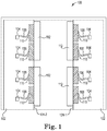
- Figure 1 is a cross-sectional view taken along a cut line X-X in Figure 2 of an example of a frame 100 including a plurality of electronics racks 102 with a number of heat receiving structures/blocks 110 according to the present disclosure.
- the frame 100 including the plurality of electronics racks 102 can include a rack mounting infrastructure to house electronic components or other types of heat producing equipment, although an electronics rack is not limited to housing the stated types of equipment.
- an electronics rack 102 can include a standard 19 inch rack.
- a standard 19 inch rack includes a front panel that is 19 inches wide, which includes the edges to which electronic components are mounted.
- an electronics rack 102 can include a front panel that is 23 inches wide.
- the frame including an electronics rack 102 can be 42 units (U) tall, although an electronics rack is not limited to a height of 42 units.
- a unit (U) is one rack unit, which is an industry standard.
- a unit (U) may have a height equal to approximately 1.75 inches.
- an electronics rack 102 can include a number of processors 104, a number of heat pipes 106, a number of heat blocks 110, and a number heat receiving structures 112.
- an electronics rack can include a front panel, a back panel, a number of side panels, and a number of internal panels.
- An inner panel can include a face which can be parallel to a direction in which computing devices slide into an electronics rack and perpendicular to the front of an electronics rack.
- an electronics rack 102 can include a first internal panel 124-1 and a second internal panel 124-2 (referred to generally as internal panels 124).
- an electronics rack 102 can include a number of electronic components (e.g., electronic devices, computing devices, etc.).
- an electronics rack 102 can include computing devices in a High Performance Computing (HPC) environment 102.
- Computing devices can include server devices, storage devices and other computation centered devices having a number of processors 104.
- Processors can include processor chips or other electronic components that generate heat.
- Processors chips can include a core parallel processing units, graphics processing units (e.g., GPUs), and/or other integrated circuits and processing units.
- Electronic components that generate heat can include hard drives, memory DIMMs (e.g., dual in-line memory modules), and other forms of electronic storage.
- a processor 104 can be thermally coupled to heat pipes 106.
- a heat pipe 106 can transfer heat between two solid interfaces.
- a heat pipe 106 can include a sealed pipe or tube that can be made from a material with high thermal conductivity. Examples of materials with high thermal conductivity include copper and aluminum, although other materials with high thermal conductivity can be used.
- a heat pipe 106 e.g., sealed pipe, can have all the air removed from the pipe. The sealed pipe can then have the air replaced with small amounts of a fluid to create a partial vacuum. Examples of fluid used in heat pipes 106 can include water, ethanol, acetone, sodium, and mercury among other fluids.
- a heat pipe 106 can include an evaporator and a condenser.
- an evaporator of a heat pipe 106 can be thermally coupled to a first solid surface.
- the first solid surface can be thermally coupled to a processor 104.
- a condenser of a heat pipe can be thermally coupled to a second solid surface.
- the second solid surface can be thermally coupled to a heat block 110.
- the fluid in a heat pipe can arrive at the evaporator of a heat pipe 106 in a liquid phase.
- the fluid can transform from a liquid phase to a vapor phase as the fluid is heated at the evaporator of a heat pipe 106.
- the vapors can travel from the evaporator of a heat pipe 106 to the condenser of a heat pipe 106.
- the fluid can re-transform from a vapor phase to a liquid phase as the fluid condenses when it reaches the condenser of a heat pipe 106.
- the walls of a heat pipe can include a wicking structure to exert capillary pressure on the fluid in a liquid phase at the condenser of the heat pipe 106.
- the wicking structure can cause the condensed liquid to flow back to the evaporator of a heat pipe 106. In this manner the fluid in a heat pipe 106 can transfer heat from a processor 104 to a heat block 110.
- Heat pipes can have some limitations. For example, heat pipes can be limited to transferring small heat loads over relatively short distances. A distance can be relatively short as compared to the dimensions and properties of a heat pipe. Heat pipes can lose some of their heat transferring properties when heat pipes transfer large heat loads over long distances. For example, heat pipes can lose some of their heat transferring properties when there is pressure loss in the heat pipes. Pressure loss can occur when fluid has to travel over a relatively long distance due to the liquid flow through the wicking structure and the viscous interaction between the fluid in a liquid phase and the fluid in a vapor phase.
- a number of heat pipes 106 can be directed toward a first internal panel 124-1 and/or a second internal panel 124-2 associated with in an electronics rack 102.
- the number of heat pipes 106 can be directed toward internal panels 124 to control the distance between the number of processors 104 and a number of heat blocks 110.
- the number of heat pipes 106 can be directed toward internal panels 124 to control the complexity of the pipe system that connects the number of heat pipes 106 to the number of heat blocks 110.
- a number of heat pipes 106 can be thermally coupled to a number of heat blocks 110.
- a heat block 110 can include a square or a rectangular piece of material, although heat blocks can include other shapes.
- materials used in heat blocks can include aluminum and copper, although a heat block can be made from other materials and composites and/or alloys as well.
- Aluminum and copper can be used because the heat conductivity of aluminum and copper is greater than the heat conductivity of most materials.
- aluminum and copper can be used because of their conductive properties, ease of manufacturing, and compatability with heat pipes.
- a number of heat blocks 110 can be connected to one side, e.g., a first side, of internal panels 124 of an electronics rack 102 by a very high bond strength (VHB) adhesive.
- VHB very high bond strength
- the number of heat blocks 110 can be connected to a side of internal panels 124 by a mounting system (not shown).
- a mounting system can include a clamping mechanism or other types of mechanisms to connect a number of heat blocks 110 to internal panels 124.
- a number of heat receiving structures 112 can be connected to an opposing side, e.g., second side, of internal panels 124 in an electronics rack 102 in association with the various heat blocks 110.
- the heat receiving structures 112 can be connected to internal panels 124 by a very high bond strength (VHB) adhesive and/or mounting system (not shown) as well.
- VHB very high bond strength
- One or more heat blocks 110 can be connected to one or more heat receiving structures 112 according a particular design rule or implementation specification.
- the heat blocks 110 can be connected to the heat receiving structures 112 through internal panels 124 of an electronics rack 102.
- a number of heat blocks 110 can be connected to a number of heat receiving structures 112 by a mounting system (not shown) as well. Examples of heat receiving structures 112 are described in more detail below.
- Figure 2 illustrates an example of a frame with a with a plurality of electronics racks including a plurality of heat receiving structures mounted on an outer panel of an electronics rack, but internal to the frame, according to the present disclosure.
- electronics rack 200 can include a number of computing devices 202.
- an electronics rack can include a number of internal panels.
- an electronics rack 200 can include a first internal panel 224-1 and a second internal panel 224-2 (referred to generally herein as internal panels 224).
- an internal panel 224 can be attached to a roof 226 of an electronics rack 200 and to a floor 228 of an electronics rack 200.
- an internal panel 224 can be solid and continuous. In some examples of the present disclosure, an internal pane! 224 can be part of the structure of an electronics rack 200. For example, an internal panel 224 can be structurally integrated into an electronics rack 200. An inner panel 224 can include a face which can be parallel to a direction in which computing devices 202 slide into an electronics rack 200 and perpendicular to the front of an electronics rack 200. In some examples of the present disclosure a number of heat receiving structures 212 can be mounted on the internal panels 224.
- the placement of a number of heat receiving structures 212 in Figure 2 can protect the number of heat receiving structures 212 in Figure 2 by placing the heat receiving structures within electronics rack 200. Furthermore, the placement of a number of heat receiving structures 512 in Figure 5 can provide greater access (e.g., maintenance) to the number of heat receiving structures 512 as compared to the placement of a number of heat receiving structures 212 in Figure 2 .
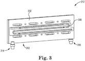
- FIG 3 illustrates a heat receiving structure with an inner serpentine channel compartment according to the present disclosure.
- the heat receiving structure 312 can be analogous to the heat receiving structure 112 illustrated in Figure 1 .
- a heat receiving structure 312 can include a liquid flow compartment.
- An example of a liquid flow compartment can be an inner serpentine channel compartment 330.
- An inner serpentine channel compartment 330 can include a number of horizontal runs and a number of vertical runs through which the heat receiving structure transfers heat to a liquid, wherein the number of horizontal runs are longer than the number of vertical runs and the number of vertical runs are oriented vertically with respect to gravity.
- the inner serpentine channel compartment 330 can be in a square or rectangular shaped piece of material 332.
- the inner serpentine channel compartment can be connected to an input 316 and to a valve 314.
- a liquid can be pumped into the heat receiving structure 312 through the input 316 and into the inner serpentine channel compartment 330.
- the heat receiving structure can transfer heat to the liquid. For example, as a liquid flows through the inner serpentine channel compartment 330 the temperature of the liquid can increase. In some examples of the present disclosure, the liquid can be released from the heat receiving structure 312 through valve 314.
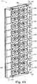
- FIG 4A illustrates a heat receiving structure with a pin fin array inner compartment according to the present disclosure.
- the heat receiving structure 412 can be analogous to the heat receiving structure 112 illustrated in Figure 1 .
- a heat receiving structure 412 can include a number of pin-fin array inner compartments and a liquid channel outer compartment 448.
- the liquid channel outer compartment 448 can include an input channel 450 and an output channel 452.
- the input channel 450 can be connected to a number of pin-fin array inner compartments through a number of openings that allow liquid to flow from an input 416 through the input channel 450 and into the number of pin-fin array inner compartments.
- the output channel 452 can be connected to the number of pin-fin array inner compartments through a number of valves 414.
- the number of valves 414 can allow liquid to exit the number of pin-fin array inner compartments into the output channel 452.
- the output channel 452 can allow liquid to flow from the number of pin-fin array inner compartments to the output 446.
- the number of pin-fin array inner compartments can be connected to the liquid channel outer compartment 448 by a mounting mechanism, although the liquid channel outer compartment 448 can be connected to the pin-fin array inner compartments by a number of means.
- the liquid channel outer compartment 448 can be connected to ten pin-fin array inner compartments, although the liquid channel outer compartment 448 can be connected to more or less pin-fin array inner compartments.
- Each pin-fin array inner compartment from the number of pin-fin array inner compartments can be connected to the output channel 452 by two valves from the number of valves 414, although each of the pin-fin array inner compartments can be connected to the output channel 452 by more or less valves.
- the valves that release liquid from the number of pin-fin array inner compartments to the output channel 452 can be configures to release liquid at a particular temperature.
- a first valve can release liquid at a first temperature and a second valve can release liquid at a second temperature.
- the different temperatures can accommodate greater flexibility in flow control and temperature control of both the liquid and the computing devices.
- the temperature of the liquid that is released through output 446 can be constant. That is, a number of valves 414 can open to release liquid as the temperature of the liquid in the number of pin-fin array inner compartments increases.
- the openings in a number of valves 414 can increase as the temperature of the liquid increases.
- the openings in a number of valves 414 can decrease as the temperature of the liquid decreases. That is, the openings in a number of valves 414 can release liquid at an increase rate or at a decreased rate depending on the temperature of the liquid.
- the temperature of the liquid that is released from the output 446 can remain constant regardless of the rate of release of the liquid from the valves 414.
- Figure 4B illustrates a cross-sectional view of an example of a heat receiving structure with a pin fin array inner compartment according to the present disclosure.
- the heat receiving structure 412 can include a liquid channel outer compartment 448 and a pin-fin array inner compartment 442.
- the heat receiving structure 412 and the liquid channel outer compartment 448 can be analogous to the heat receiving structure 412 and the liquid channel outer compartment 448 illustrated in Figure 4A .
- a pin-fin array inner compartment 442 can include a plate 454 with a number of raised sections 456.
- a number of plates can be aligned along a length of the heat receiving structure 412.
- a number of plates can be in contact with the internal panel and/or the external panel.
- Plate 454 can include a square or rectangular plate, although plate 454 can include a number of shapes and/or sizes.
- the raised sections 456 can include a number of configurations, dimensions, and/or layouts.
- the raised sections 456 can create a larger inner surface area in a pin-fin array inner compartment 442 than the inner surface area for a rectangular liquid flow compartment with no pin-fin array.
- the larger inner surface area can provide for greater heat exchange between the pin-fin array inner compartment 442 and a liquid that is flowing through the pin-fin array inner compartment because the larger surface area provides for greater contact between the liquid and the pin-fin array inner compartment 442 than a rectangular liquid flow compartment without a pin-fin array.
- the heat receiving structure 412 can receive liquid through an input that can be connected to an input channel 450.
- a pin-fin array inner compartment 442 can be connected to an input channel 450 by a number of openings.
- the liquid can flow through the input channel 450 and into the pin-fin array inner compartment 442 through an opening 458.
- a pin-fin array inner compartment 442 can be connected to an input channel by two openings, although the number of openings is illustrative and not limiting.
- the liquid can flow through the pin-fin array inner compartment 442.
- the liquid can be warmed as it passes through the pin-fin array inner compartment 442.
- the liquid can be released from the pin-fin array inner compartment 442 through a number of valves 414 into the output channel 452. The liquid can then travel through the output channel 452 and out of the heat receiving structure 412 through an output.
- the input channel 450 and the output channel 452 can be an enclosed hollow structures that allow liquid to pass through them.
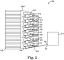
- FIG. 5 illustrates an example of an electronics rack with a number of heat receiving structures mounted on an outer side of the electronics rack according to the present disclosure.
- an electronics rack 500 can include a number of computing devices 502.
- the computing devices 502 can be thermally coupled to a number of heat receiving structures 512.
- the heat receiving structures 512 can be analogous to the heat receiving structure 112 illustrated in Figure 1 .
- a number of heat receiving structures 512 can be mounted on a side panel 508-1 on an outer side of the electronics rack 500.
- a side panel 508-1 on an outer side of the electronics rack 500 can be solid.
- side panel 508-1 can be a continuous and solid panel on the outer side of electronics rack 500.
- an outer panel can be part of the structure of an electronics rack 500.
- outer panel 508-1 can be structurally integrated into an electronics rack 500.
- a face of an outer panel (e.g., side panel 508-1) can be parallel to a direction in which a number of computing devices 502 slide into the electronics rack 500 and perpendicular to a front of the electronics rack 500.
- a number of heat receiving structures 512 can include a number of inputs 516 to allow cool liquid into a number of liquid flow compartments (not shown) in the number of heat receiving structures 512.
- a number of heat receiving structures 512 can include a number of control valves 514 to release warm liquid from the liquid flow compartment at least partially in response to the liquid reaching a particular temperature.
- a control valve can be a thermostatic flow control valve.
- a thermostatic flow control valve can include temperature sensitive materials and a valve opening. The valve opening can change as a function of the temperature of a liquid flowing through it. Temperature sensitive materials can include wax, liquid, or gas, although temperature sensitive materials are not limited to the same. Temperature sensitive materials can expand and contract depending on the temperature of a liquid flowing through the thermostatic flow control valve. For example, a thermostatic flow control valve can allow a large flow of liquid through the valve opening when the liquid has a high temperature. Alternatively, a thermostatic flow control valve can allow a small flow of liquid through the valve opening when the liquid has a low temperature.
- a thermostatic flow control valve can control the temperature of the liquid flowing from a heat receiving structure.
- a number of heat receiving structures 512 can receive cool liquid from the inputs 516.
- the liquid can extract heat from a number of heat receiving structures 512.
- the liquid flow compartments in a number of heat receiving structures 512 can give a small flow of heat to a liquid because the heat a number of receiving structures 512 can receive a small flow of heat from the computing devices.
- the thermostatic flow control valve 514 can reduce the flow of liquid because the liquid will need more time in the liquid flow compartment to reach a particular temperature.
- the liquid flow compartments in a number of heat receiving structures 512 can receive a large flow of heat from the computing devices.
- the thermostatic flow control valve 514 can increase the flow of liquid because the liquid will require less time in the liquid flow compartment to reach a particular temperature.
- a cooling system 518 can be external to the electronics rack 500. Furthermore, the cooling system 518 can include an input 522 and an output 520. Warm liquid can flow into the cooling system 518 through the input 522 and cool liquid can flow from the cooling system 518 through the output 520.
- the warm liquid that can flow into the cooling system 518 through the input 522 can be the warm liquid that flows from a number of heat receiving structures 512.
- the cool liquid that can flow from the cooling system 518 through the output 520 can be the cool liquid that can flow into a number of heat receiving structures 512.
- the cooling system 518 can be a district heating system.
- a district heating system can include distributing heat from a central location to a number of locations such as residential and commercial locations that use heat, although locations can include other locations that can use the heat.
- the heat generated by the electronics rack 500 can be used to heat residential and/or commercial buildings.
- the electronics rack 500 can be used to heat residential and/or commercial buildings that house the electronics rack 500.
- the electronics rack 500 can be used to heat residential and/or commercial buildings that do not house the electronics rack 500.
- the warm liquid that flows from the thermostatic flow control valves 514 can flow into an input 522 of a heating system of a commercial building.
- the commercial building can cool the liquid which can then be pumped into the inputs 516 of a number of heat receiving structures 512 from the output 520 of a heating system of a commercial building.
- the cooling system 518 can be an environmental cooling system.
- An environmental cooling system can include releasing heat into the open air.
- Open air can be any area that is not enclosed by a structure (e.g., a building).
- An environmental cooling system can release heat into the open air by circulating warm liquid from an electronics rack through the open air (e.g., area not enclosed by a structure). Circulating liquid through the open air can be useful in locations where outside temperature is low compared to the temperature of the warm liquid.
Claims (11)
- Système de refroidissement à régulation de température de liquide pour un rack électronique (500), à l'intérieur d'un châssis, le système comprenant :un certain nombre de dispositifs informatiques (502) dans le rack électronique (500) ;un bloc thermique (110) ayant un bloc conducteur de chaleur monté à l'intérieur du rack électronique (500) sur un côté solide continu définissant un panneau intérieur du rack électronique (500) ;un certain nombre de caloducs (106) conçus pour transférer la chaleur d'une interface solide des dispositifs informatiques (502) à une interface solide du bloc thermique (110) ; etune structure de réception de chaleur (512), à l'extérieur du rack électronique (500) et interne au châssis, qui est thermiquement couplée au bloc thermique (110) par l'intermédiaire du panneau intérieur (124) du rack électronique (500), et qui est configurée pour recevoir de la chaleur à partir de celui-ci, dans lequel la structure de réception de chaleur (512) comporte :un compartiment d'écoulement de liquide (330) ;une entrée (516) configurée pour recevoir du liquide froid dans le compartiment d'écoulement de liquide (330) ; etun certain nombre de vannes de commande de l'écoulement (514) configurées pour libérer un liquide chaud à partir du compartiment d'écoulement de liquide (330) au moins partiellement en réponse à une température spécifique atteinte par le liquide.
- Système selon la revendication 1, comprenant en outre une structure de refroidissement (518) qui est connectée à l'entrée (516) et le nombre de vannes de commande de l'écoulement (514), dans lequel la structure de refroidissement (518) est conçue pour refroidir le liquide et dans lequel le nombre de vannes de commande de l'écoulement (514) comporte un certain nombre de vannes de commande de l'écoulement thermostatiques.
- Système selon la revendication 1, dans lequel :un premier groupe du nombre de vannes de commande de l'écoulement (514) est configuré pour libérer un liquide chaud lorsque le liquide atteint une première température spécifique ;un deuxième groupe du nombre de vannes de commande de l'écoulement (514) est configuré pour libérer un liquide chaud en réponse à une deuxième température spécifique atteinte par le liquide, dans lequel la première température spécifique est supérieure à la deuxième température spécifique ; etle premier groupe du nombre de vannes de commande de l'écoulement (514) et le deuxième groupe du nombre de vannes de commande de l'écoulement (514) sont conçus pour commander un écoulement du liquide, une température d'un liquide et une température du nombre de dispositifs informatiques (502).
- Système selon la revendication 1, dans lequel le nombre de caloducs (106) est thermiquement couplé aux dispositifs informatiques (502).
- Système selon la revendication 1, dans lequel le bloc thermique est monté à l'opposé de la structure de réception de chaleur, et dans lequel le couplage thermique entre le bloc thermique et la structure de réception de chaleur s'effectue par l'intermédiaire du côté du rack électronique.
- Système selon la revendication 1, dans lequel le côté du rack (500) comporte un emplacement de montage où le bloc thermique (110) est monté à l'opposé de la structure de réception de chaleur (512) et dans lequel l'emplacement de montage comporte un matériau qui améliore la conductivité thermique.
- Système selon l'une quelconque des revendications précédentes, dans lequel le compartiment d'écoulement de liquide comporte un compartiment à matrice d'ailettes en forme de broches, un canal d'entrée et un canal de sortie ; et
le compartiment à matrice d'ailettes en forme de broches comporte une plaque avec un certain nombre de sections surélevées par lesquelles la chaleur est transférée au liquide et le nombre de vannes de commande est configuré pour libérer un liquide chaud à partir du compartiment à matrice d'ailettes en forme de broches au moins partiellement en réponse à une température spécifique atteinte par le liquide. - Procédé de réalisation d'un système de refroidissement à régulation de température de liquide pour un rack électronique (500), à l'intérieur d'un châssis, comprenant :la réalisation d'un panneau (508-1) dans le rack électronique (500) parallèle à un certain nombre de dispositifs électroniques (502) dans le rack électronique (500) et perpendiculaire à un avant du rack électronique (500), le panneau (508-1), qui est un côté solide continu du rack électronique (500) ayant un certain nombre de blocs thermiques (110) fixés sur le panneau à l'intérieur du rack électronique et au moins une structure de réception de chaleur (512) fixée au panneau à l'extérieur du rack électronique pour recevoir de la chaleur à partir du nombre de blocs thermiques (110) ;la réalisation d'un certain nombre de caloducs (106) pour transférer de la chaleur du nombre de dispositifs électroniques (502) au nombre de blocs thermiques conducteurs de chaleur (110) ;la réalisation d'une entrée de liquide froid dans la structure de réception de chaleur (512) pour refroidir la structure de réception de chaleur (512) ;la réalisation d'une vanne de commande de l'écoulement thermostatique (514) sur la structure de réception de chaleur (512) pour libérer un liquide chaud au moins partiellement en réponse à une température spécifique atteinte par le liquide ; etla réalisation d'un système de refroidissement (518) qui est externe au rack électronique (500) et au châssis, pour refroidir le liquide libéré à partir de la vanne de commande de l'écoulement thermostatique (514).
- Procédé selon la revendication 8, dans lequel la réalisation du système de refroidissement externe (518) comporte la réalisation d'une connexion entre un système de chauffage centralisé, externe au rack (500), et la vanne de commande de l'écoulement thermostatique (514) pour refroidir le liquide qui est libéré à partir de la structure de réception de chaleur (512) via un bâti comportant le système de chauffage centralisé.
- Procédé selon la revendication 8, dans lequel la réalisation du système de refroidissement externe (518) comporte la réalisation d'une connexion entre un système de refroidissement environnemental, externe au rack (500), et la vanne de commande de l'écoulement thermostatique (514) pour refroidir le liquide qui est libéré à partir de la structure de réception de chaleur (512) via des températures atmosphériques dans le système de refroidissement environnemental.
- Procédé selon la revendication 8, dans lequel la réalisation du panneau (508-1) comporte :la réalisation d'un panneau (508-1) dans lequel la structure de réception de chaleur (512) est intégrée dans le panneau (508-1) ;la réalisation d'un panneau (508-1) qui fait partie d'une structure du rack électronique (500) ; etla réalisation d'un panneau (508-1) qui s'étend à partir d'un toit (226) du rack électronique (500) jusqu'à un plancher (228) du rack électronique (500).
Applications Claiming Priority (1)
| Application Number | Priority Date | Filing Date | Title |
|---|---|---|---|
| PCT/US2012/028718 WO2013137847A1 (fr) | 2012-03-12 | 2012-03-12 | Refroidissement à régulation de température de liquide |
Publications (3)
| Publication Number | Publication Date |
|---|---|
| EP2826347A1 EP2826347A1 (fr) | 2015-01-21 |
| EP2826347A4 EP2826347A4 (fr) | 2015-11-11 |
| EP2826347B1 true EP2826347B1 (fr) | 2017-10-25 |
Family
ID=49161594
Family Applications (1)
| Application Number | Title | Priority Date | Filing Date |
|---|---|---|---|
| EP12871455.7A Active EP2826347B1 (fr) | 2012-03-12 | 2012-03-12 | Refroidissement à régulation de température de liquide |
Country Status (5)
| Country | Link |
|---|---|
| US (1) | US9529395B2 (fr) |
| EP (1) | EP2826347B1 (fr) |
| KR (1) | KR20140132333A (fr) |
| CN (1) | CN104094682B (fr) |
| WO (1) | WO2013137847A1 (fr) |
Families Citing this family (16)
| Publication number | Priority date | Publication date | Assignee | Title |
|---|---|---|---|---|
| CN104919914B (zh) | 2013-01-31 | 2017-10-27 | 慧与发展有限责任合伙企业 | 用于提供液体冷却的组件、系统以及移除热量的方法 |
| US20160366792A1 (en) * | 2014-05-28 | 2016-12-15 | Hewlett Packard Enterprise Development Lp | Multiple tank cooling system |
| EP3040766B1 (fr) * | 2015-01-05 | 2018-01-31 | Samsung Electronics Co., Ltd. | Dispositif d'affichage |
| US10185375B2 (en) | 2015-02-13 | 2019-01-22 | Hewlett Packard Enterprise Development Lp | Thermal bus bar |
| CN105241288A (zh) * | 2015-10-26 | 2016-01-13 | 楹联新能源科技南通有限公司 | 一种新型、高效的恒温模组 |
| US9968010B2 (en) * | 2015-12-21 | 2018-05-08 | Dell Products, L.P. | Information handling system having flexible chassis block radiators |
| US10492341B2 (en) * | 2016-07-07 | 2019-11-26 | Commscope Technologies Llc | Modular data center |
| JP6791364B2 (ja) * | 2017-03-29 | 2020-11-25 | 日本電気株式会社 | 管理装置、管理方法およびプログラム |
| CN107104086B (zh) * | 2017-05-18 | 2019-01-29 | 苏州汇川联合动力系统有限公司 | 液冷散热装置及电机控制器 |
| KR101817333B1 (ko) * | 2017-06-16 | 2018-01-10 | 윤도현 | 서버냉각시스템 |
| US10368467B2 (en) | 2017-10-10 | 2019-07-30 | Facebook, Inc. | System and method for data center heat containment |
| KR102602408B1 (ko) | 2018-06-15 | 2023-11-14 | 현대자동차주식회사 | 운송 수단의 연료 전지용 전해질막의 조성물 및 운송 수단의 연료 전지용 전해질막의 제조 방법 |
| CN110678045A (zh) * | 2019-09-30 | 2020-01-10 | 联想(北京)有限公司 | 一种散热系统 |
| EP4268023A1 (fr) * | 2021-03-11 | 2023-11-01 | Hewlett-Packard Development Company, L.P. | Échange de chaleur et arrêt des flammes |
| CA3153037A1 (fr) | 2021-04-01 | 2022-10-01 | Ovh | Systeme hybride de refroidissement par immersion pour les ensembles electroniques montes sur bati |
| US11729950B2 (en) | 2021-04-01 | 2023-08-15 | Ovh | Immersion cooling system with dual dielectric cooling liquid circulation |
Citations (1)
| Publication number | Priority date | Publication date | Assignee | Title |
|---|---|---|---|---|
| US20080259566A1 (en) * | 2007-04-16 | 2008-10-23 | Stephen Samuel Fried | Efficiently cool data centers and electronic enclosures using loop heat pipes |
Family Cites Families (153)
| Publication number | Priority date | Publication date | Assignee | Title |
|---|---|---|---|---|
| US5228385A (en) | 1992-03-03 | 1993-07-20 | Friedrich Metal Products Co., Inc. | Convection oven for bakery goods |
| US5370178A (en) | 1993-08-25 | 1994-12-06 | International Business Machines Corporation | Convertible cooling module for air or water cooling of electronic circuit components |
| US5514906A (en) | 1993-11-10 | 1996-05-07 | Fujitsu Limited | Apparatus for cooling semiconductor chips in multichip modules |
| US5505533A (en) | 1994-01-10 | 1996-04-09 | Artecon | Rackmount for computer and mass storage enclosure |
| US6333849B1 (en) * | 1996-07-01 | 2001-12-25 | Compaq Computer Corporation | Apparatus for liquid cooling of specific computer components |
| US6111749A (en) | 1996-09-25 | 2000-08-29 | International Business Machines Corporation | Flexible cold plate having a one-piece coolant conduit and method employing same |
| US5867369A (en) | 1997-07-15 | 1999-02-02 | Sun Microsystems, Inc. | Rugged computer housing |
| US6084769A (en) | 1997-08-20 | 2000-07-04 | Compaq Computer Corporation | Docking station with auxiliary heat dissipation system for a docked portable computer |
| US5982616A (en) | 1997-08-20 | 1999-11-09 | Compaq Computer Corporation | Electronic apparatus with plug-in heat pipe module cooling system |
| US5986882A (en) | 1997-10-16 | 1999-11-16 | Compaq Computer Corporation | Electronic apparatus having removable processor/heat pipe cooling device modules therein |
| JPH11220281A (ja) | 1998-01-30 | 1999-08-10 | Nec Eng Ltd | パネル類収容用シェルフ等の間のシール構造 |
| JP3315649B2 (ja) | 1998-08-11 | 2002-08-19 | 富士通株式会社 | 電子機器 |
| US6234842B1 (en) | 1998-11-20 | 2001-05-22 | Vlt Corporation | Power converter connector assembly |
| US6377453B1 (en) | 1999-01-29 | 2002-04-23 | Hewlett-Packard Company | Field replaceable module with enhanced thermal interface |
| GB2354062A (en) | 1999-09-13 | 2001-03-14 | British Broadcasting Corp | Cooling system for use in cooling electronic equipment |
| AU2001249286A1 (en) | 2000-03-21 | 2001-10-03 | Liebert Corporation | Method and apparatus for cooling electronic enclosures |
| US6498725B2 (en) * | 2001-05-01 | 2002-12-24 | Mainstream Engineering Corporation | Method and two-phase spray cooling apparatus |
| CN2519983Y (zh) | 2001-11-30 | 2002-11-06 | 施水源 | 并列四个硬碟机的伺服器 |
| US6594148B1 (en) | 2002-01-16 | 2003-07-15 | Cisco Technology, Inc. | Airflow system |
| US6879486B1 (en) | 2002-02-14 | 2005-04-12 | Mercury Computer Systems, Inc. | Central inlet circuit board assembly |
| AU2003223231A1 (en) | 2002-03-05 | 2003-12-31 | Sri International | Electroactive polymer devices for controlling fluid flow |
| DE10210480B4 (de) * | 2002-03-11 | 2005-07-21 | Rittal Gmbh & Co. Kg | Kühlanordnung |
| DK174881B1 (da) | 2002-05-08 | 2004-01-19 | Danfoss Silicon Power Gmbh | Anordning med flere køleceller til køling af halvledere |
| US6600649B1 (en) | 2002-05-24 | 2003-07-29 | Mei-Nan Tsai | Heat dissipating device |
| US6704198B2 (en) | 2002-06-12 | 2004-03-09 | Avava Technology Corp. | Equipment enclosure with heat exchanger |
| JP3757200B2 (ja) | 2002-09-25 | 2006-03-22 | 株式会社日立製作所 | 冷却機構を備えた電子機器 |
| JP4199018B2 (ja) * | 2003-02-14 | 2008-12-17 | 株式会社日立製作所 | ラックマウントサーバシステム |
| US20040201335A1 (en) | 2003-03-28 | 2004-10-14 | Brooks Davis | Universal computer enclosure |
| US7112131B2 (en) | 2003-05-13 | 2006-09-26 | American Power Conversion Corporation | Rack enclosure |
| US6987673B1 (en) | 2003-09-09 | 2006-01-17 | Emc Corporation | Techniques for cooling a set of circuit boards within a rack mount cabinet |
| EP1682995A2 (fr) | 2003-11-07 | 2006-07-26 | Asetek A/S | Systeme de refroidissement pour ordinateur |
| US7106590B2 (en) | 2003-12-03 | 2006-09-12 | International Business Machines Corporation | Cooling system and method employing multiple dedicated coolant conditioning units for cooling multiple electronics subsystems |
| US7508663B2 (en) | 2003-12-29 | 2009-03-24 | Rackable Systems, Inc. | Computer rack cooling system with variable airflow impedance |
| JP2005228216A (ja) | 2004-02-16 | 2005-08-25 | Hitachi Ltd | 電子機器 |
| TWM254049U (en) | 2004-03-03 | 2004-12-21 | Mitac Int Corp | Free of screw structure for top cover of server case |
| US7647787B2 (en) | 2004-04-22 | 2010-01-19 | Hewlett-Packard Development Company, L.P. | Upgradeable, modular data center cooling apparatus |
| US7236370B2 (en) | 2004-05-07 | 2007-06-26 | Rackable Systems, Inc. | Computer rack with cluster modules |
| US7372695B2 (en) | 2004-05-07 | 2008-05-13 | Rackable Systems, Inc. | Directional fan assembly |
| US7529097B2 (en) | 2004-05-07 | 2009-05-05 | Rackable Systems, Inc. | Rack mounted computer system |
| US7019974B2 (en) * | 2004-07-16 | 2006-03-28 | Hon Hai Precision Industry Co., Ltd. | Heat dissipation device |
| US7380409B2 (en) * | 2004-09-30 | 2008-06-03 | International Business Machines Corporation | Isolation valve and coolant connect/disconnect assemblies and methods of fabrication for interfacing a liquid cooled electronics subsystem and an electronics housing |
| CN100539817C (zh) | 2004-11-16 | 2009-09-09 | 富士通株式会社 | 通信装置以及架结构 |
| US7218129B2 (en) | 2005-01-12 | 2007-05-15 | International Business Machines Corporation | System, apparatus and method for controlling temperature of an integrated circuit under test |
| WO2006083443A2 (fr) | 2005-02-02 | 2006-08-10 | Carrier Corporation | Echangeurs thermiques a flux parallele renfermant des elements d'insertion poreux |
| JP2006215882A (ja) * | 2005-02-04 | 2006-08-17 | Hitachi Ltd | ディスクアレイ装置及びその液冷装置 |
| US7286345B2 (en) | 2005-02-08 | 2007-10-23 | Rackable Systems, Inc. | Rack-mounted air deflector |
| US20090065178A1 (en) | 2005-04-21 | 2009-03-12 | Nippon Light Metal Company, Ltd. | Liquid cooling jacket |
| CN100499089C (zh) | 2005-06-08 | 2009-06-10 | 富准精密工业(深圳)有限公司 | 散热装置 |
| CN1913760A (zh) | 2005-08-12 | 2007-02-14 | 鸿富锦精密工业(深圳)有限公司 | 液冷式散热系统 |
| US7393236B2 (en) | 2005-09-02 | 2008-07-01 | Gm Global Technology Operations, Inc. | Integrated thermal and electrical connection system for power devices |
| US7900692B2 (en) | 2005-10-28 | 2011-03-08 | Nakamura Seisakusho Kabushikigaisha | Component package having heat exchanger |
| US8051897B2 (en) | 2005-11-30 | 2011-11-08 | International Business Machines Corporation | Redundant assembly for a liquid and air cooled module |
| CN101438638B (zh) | 2006-02-16 | 2015-01-14 | 库利吉公司 | 服务器应用的液体冷却回路 |
| US7718891B2 (en) | 2006-03-13 | 2010-05-18 | Panduit Corp. | Network cabinet |
| US7715194B2 (en) | 2006-04-11 | 2010-05-11 | Cooligy Inc. | Methodology of cooling multiple heat sources in a personal computer through the use of multiple fluid-based heat exchanging loops coupled via modular bus-type heat exchangers |
| US7298619B1 (en) | 2006-05-02 | 2007-11-20 | Hewlett-Packard Development Company, L.P. | Cable management arm with integrated heat exchanger |
| ITPD20060176A1 (it) | 2006-05-05 | 2007-11-06 | Liebert Hiross Spa | Apparecchiatura perfezionata per il condizionamento di racks per strumenti elettrici, elettronici, di telecomunicazioni e simili |
| US7403392B2 (en) * | 2006-05-16 | 2008-07-22 | Hardcore Computer, Inc. | Liquid submersion cooling system |
| EP1860695A3 (fr) | 2006-05-24 | 2010-06-16 | Raytheon Company | Système et procédé de refroidissement par projection de jet sur des surfaces étendues |
| US7701714B2 (en) | 2006-05-26 | 2010-04-20 | Flextronics Ap, Llc | Liquid-air hybrid cooling in electronics equipment |
| WO2007139560A1 (fr) | 2006-06-01 | 2007-12-06 | Google, Inc. | Environnements informatiques modulaires |
| US8757246B2 (en) | 2006-06-06 | 2014-06-24 | Raytheon Company | Heat sink and method of making same |
| US20070291452A1 (en) | 2006-06-14 | 2007-12-20 | Gilliland Don A | Heat Transfer Systems for Dissipating Thermal Loads From a Computer Rack |
| US7768780B2 (en) | 2006-06-19 | 2010-08-03 | Silicon Graphics International Corp. | Flow-through cooling for computer systems |
| US20070297136A1 (en) | 2006-06-23 | 2007-12-27 | Sun Micosystems, Inc. | Modular liquid cooling of electronic components while preserving data center integrity |
| JP5283836B2 (ja) | 2006-07-25 | 2013-09-04 | 富士通株式会社 | 液冷ユニット用受熱器および液冷ユニット並びに電子機器 |
| US7403384B2 (en) * | 2006-07-26 | 2008-07-22 | Dell Products L.P. | Thermal docking station for electronics |
| US8327656B2 (en) * | 2006-08-15 | 2012-12-11 | American Power Conversion Corporation | Method and apparatus for cooling |
| US8322155B2 (en) * | 2006-08-15 | 2012-12-04 | American Power Conversion Corporation | Method and apparatus for cooling |
| US7397661B2 (en) | 2006-08-25 | 2008-07-08 | International Business Machines Corporation | Cooled electronics system and method employing air-to-liquid heat exchange and bifurcated air flow |
| US7856838B2 (en) * | 2006-09-13 | 2010-12-28 | Oracle America, Inc. | Cooling air flow loop for a data center in a shipping container |
| US7450378B2 (en) | 2006-10-25 | 2008-11-11 | Gm Global Technology Operations, Inc. | Power module having self-contained cooling system |
| TWM312877U (en) | 2006-11-03 | 2007-05-21 | Hon Hai Prec Ind Co Ltd | Mounting assembly for disk drive bracket |
| US7564685B2 (en) | 2006-12-29 | 2009-07-21 | Google Inc. | Motherboards with integrated cooling |
| CN101680718A (zh) | 2007-03-14 | 2010-03-24 | 佐尼特结构解决方案有限责任公司 | 用于数据中心机架的基于空气的冷却 |
| JP5030631B2 (ja) * | 2007-03-22 | 2012-09-19 | 富士通株式会社 | 情報機器の冷却システム |
| US8118084B2 (en) | 2007-05-01 | 2012-02-21 | Liebert Corporation | Heat exchanger and method for use in precision cooling systems |
| US7688578B2 (en) | 2007-07-19 | 2010-03-30 | Hewlett-Packard Development Company, L.P. | Modular high-density computer system |
| TW200910068A (en) | 2007-08-20 | 2009-03-01 | Asustek Comp Inc | Heat dissipation apparatus |
| US7539013B2 (en) | 2007-09-27 | 2009-05-26 | International Business Machines Corporation | Automatic air blockage assembly and method for computing environments |
| US7907402B2 (en) | 2007-11-09 | 2011-03-15 | Panduit Corp. | Cooling system |
| US7764494B2 (en) | 2007-11-20 | 2010-07-27 | Basic Electronics, Inc. | Liquid cooled module |
| US7916480B2 (en) | 2007-12-19 | 2011-03-29 | GM Global Technology Operations LLC | Busbar assembly with integrated cooling |
| KR100944890B1 (ko) | 2008-01-14 | 2010-03-03 | 에버테크노 주식회사 | 에스에스디(ssd) 테스트 핸들러의 테스트 트레이 |
| US7808780B2 (en) | 2008-02-28 | 2010-10-05 | International Business Machines Corporation | Variable flow computer cooling system for a data center and method of operation |
| US7907409B2 (en) | 2008-03-25 | 2011-03-15 | Raytheon Company | Systems and methods for cooling a computing component in a computing rack |
| US8164901B2 (en) * | 2008-04-16 | 2012-04-24 | Julius Neudorfer | High efficiency heat removal system for rack mounted computer equipment |
| CN102037426B (zh) | 2008-04-21 | 2014-08-06 | 固核电脑公司 | 一种液体浸没式冷却式服务器电脑阵列、服务器电脑 |
| JP5002522B2 (ja) | 2008-04-24 | 2012-08-15 | 株式会社日立製作所 | 電子機器用冷却装置及びこれを備えた電子機器 |
| US10058011B2 (en) | 2008-06-19 | 2018-08-21 | Panduit Corp. | Passive cooling systems for network cabinet |
| KR20110027766A (ko) | 2008-07-09 | 2011-03-16 | 휴렛-팩커드 디벨롭먼트 컴퍼니, 엘.피. | 컴퓨터 섀시 챔버를 위한 전용의 공기 흡입구 및 공기 배출구 |
| JP2010041007A (ja) * | 2008-08-08 | 2010-02-18 | Hitachi Information & Communication Engineering Ltd | 冷却ユニット、電子装置ラック、冷却システム及びその構築方法 |
| US20100032142A1 (en) | 2008-08-11 | 2010-02-11 | Sun Microsystems, Inc. | Liquid cooled rack with optimized air flow rate and liquid coolant flow |
| JP5023020B2 (ja) | 2008-08-26 | 2012-09-12 | 株式会社豊田自動織機 | 液冷式冷却装置 |
| US7961475B2 (en) * | 2008-10-23 | 2011-06-14 | International Business Machines Corporation | Apparatus and method for facilitating immersion-cooling of an electronic subsystem |
| US7983040B2 (en) * | 2008-10-23 | 2011-07-19 | International Business Machines Corporation | Apparatus and method for facilitating pumped immersion-cooling of an electronic subsystem |
| US7885070B2 (en) * | 2008-10-23 | 2011-02-08 | International Business Machines Corporation | Apparatus and method for immersion-cooling of an electronic system utilizing coolant jet impingement and coolant wash flow |
| US7916483B2 (en) | 2008-10-23 | 2011-03-29 | International Business Machines Corporation | Open flow cold plate for liquid cooled electronic packages |
| US20120004172A1 (en) | 2008-10-27 | 2012-01-05 | Oncotherapy Science, Inc. | Screening method of anti-lung or esophageal cancer compounds |
| WO2010062469A1 (fr) | 2008-10-31 | 2010-06-03 | Liebert Corporation | Bâti à montage vertical ménageant de l'espace pour une unité de distribution de puissance en bâti |
| US7724524B1 (en) * | 2008-11-12 | 2010-05-25 | International Business Machines Corporation | Hybrid immersion cooled server with integral spot and bath cooling |
| GB2477651A (en) | 2008-12-05 | 2011-08-10 | Commscope Inc | Modular rack controllers for patching systems |
| DE102008061489A1 (de) | 2008-12-10 | 2010-06-17 | Siemens Aktiengesellschaft | Stromrichtermodul mit gekühlter Verschienung |
| US7990710B2 (en) | 2008-12-31 | 2011-08-02 | Vs Acquisition Co. Llc | Data center |
| US8305759B2 (en) * | 2009-03-09 | 2012-11-06 | Hardcore Computer, Inc. | Gravity assisted directed liquid cooling |
| US8297069B2 (en) | 2009-03-19 | 2012-10-30 | Vette Corporation | Modular scalable coolant distribution unit |
| US20100248609A1 (en) | 2009-03-24 | 2010-09-30 | Wright Line, Llc | Assembly For Providing A Downflow Return Air Supply |
| US10212858B2 (en) | 2009-04-21 | 2019-02-19 | Excalibur Ip, Llc | Cold row encapsulation for server farm cooling system |
| US7800900B1 (en) | 2009-04-21 | 2010-09-21 | Yahoo! Inc. | Cold row encapsulation for server farm cooling system |
| US8369090B2 (en) * | 2009-05-12 | 2013-02-05 | Iceotope Limited | Cooled electronic system |
| US8582298B2 (en) * | 2009-06-22 | 2013-11-12 | Xyber Technologies | Passive cooling enclosure system and method for electronics devices |
| US8490679B2 (en) | 2009-06-25 | 2013-07-23 | International Business Machines Corporation | Condenser fin structures facilitating vapor condensation cooling of coolant |
| US8014150B2 (en) | 2009-06-25 | 2011-09-06 | International Business Machines Corporation | Cooled electronic module with pump-enhanced, dielectric fluid immersion-cooling |
| US8583290B2 (en) * | 2009-09-09 | 2013-11-12 | International Business Machines Corporation | Cooling system and method minimizing power consumption in cooling liquid-cooled electronics racks |
| US8208258B2 (en) | 2009-09-09 | 2012-06-26 | International Business Machines Corporation | System and method for facilitating parallel cooling of liquid-cooled electronics racks |
| US8194406B2 (en) | 2009-09-23 | 2012-06-05 | International Business Machines Corporation | Apparatus and method with forced coolant vapor movement for facilitating two-phase cooling of an electronic device |
| US8027162B2 (en) | 2009-09-24 | 2011-09-27 | International Business Machines Corporation | Liquid-cooled electronics apparatus and methods of fabrication |
| US8262041B2 (en) | 2009-09-29 | 2012-09-11 | American Power Conversion Corporation | Tool-less installation system and method of U-mounted devices |
| GB0922095D0 (en) | 2009-12-17 | 2010-02-03 | Bripco Bvba | Data centre building and rack therefor |
| EP2354378A1 (fr) | 2010-02-01 | 2011-08-10 | Dataxenter IP B.V. | Élément modulaire de centre informatique et élément modulaire de refroidissement de centre informatique |
| TWI394524B (zh) | 2010-02-10 | 2013-04-21 | Delta Electronics Inc | 模組化散熱裝置 |
| CN201654658U (zh) | 2010-03-10 | 2010-11-24 | 广东威创视讯科技股份有限公司 | 一种可防尘防水的密闭型机箱散热装置 |
| CN102189311B (zh) | 2010-03-10 | 2015-02-04 | 株式会社大亨 | 电源装置 |
| US8755192B1 (en) | 2010-03-31 | 2014-06-17 | Amazon Technologies, Inc. | Rack-mounted computer system with shock-absorbing chassis |
| US20110240281A1 (en) | 2010-03-31 | 2011-10-06 | Industrial Idea Partners, Inc. | Liquid-Based Cooling System For Data Centers Having Proportional Flow Control Device |
| CN101893921A (zh) | 2010-04-08 | 2010-11-24 | 山东高效能服务器和存储研究院 | 无噪音节能服务器 |
| WO2011133166A1 (fr) | 2010-04-23 | 2011-10-27 | Rostra Vernatherm LLC | Protection antigel intégrée et soupape de décharge |
| US9038406B2 (en) * | 2010-05-26 | 2015-05-26 | International Business Machines Corporation | Dehumidifying cooling apparatus and method for an electronics rack |
| US8351206B2 (en) * | 2010-06-29 | 2013-01-08 | International Business Machines Corporation | Liquid-cooled electronics rack with immersion-cooled electronic subsystems and vertically-mounted, vapor-condensing unit |
| US8259450B2 (en) | 2010-07-21 | 2012-09-04 | Birchbridge Incorporated | Mobile universal hardware platform |
| TW201210454A (en) * | 2010-08-24 | 2012-03-01 | Hon Hai Prec Ind Co Ltd | Server cabinet and liquid cooling system thereof |
| WO2012027319A1 (fr) * | 2010-08-26 | 2012-03-01 | Asetek A/S | Système de refroidissement de liquide pour serveur |
| US8089766B2 (en) * | 2010-08-30 | 2012-01-03 | Hardcore Computer, Inc. | Server case with optical input/output and/or wireless power supply |
| WO2012036754A1 (fr) | 2010-09-14 | 2012-03-22 | King Saud University | Procédés de codage et de décodage de jonctions afin d'améliorer les performances en termes de taux d'erreurs |
| US8400765B2 (en) | 2010-09-20 | 2013-03-19 | Amazon Technologies, Inc. | System with air flow under data storage devices |
| US8838286B2 (en) | 2010-11-04 | 2014-09-16 | Dell Products L.P. | Rack-level modular server and storage framework |
| TW201221034A (en) | 2010-11-05 | 2012-05-16 | Inventec Corp | Cooling system of server and cooling method thereof |
| TWI392432B (zh) * | 2010-11-23 | 2013-04-01 | Inventec Corp | 一種伺服器機櫃 |
| TW201228570A (en) | 2010-12-17 | 2012-07-01 | Hon Hai Prec Ind Co Ltd | Liquid heat dissipation device |
| CN102159058B (zh) | 2011-03-18 | 2013-10-09 | 致茂电子(苏州)有限公司 | 液冷式散热结构 |
| US9845981B2 (en) * | 2011-04-19 | 2017-12-19 | Liebert Corporation | Load estimator for control of vapor compression cooling system with pumped refrigerant economization |
| US20120293951A1 (en) | 2011-05-16 | 2012-11-22 | Delta Electronics, Inc. | Rack mounted computer system and cooling structure thereof |
| CN202120175U (zh) | 2011-06-28 | 2012-01-18 | 纬创资通股份有限公司 | 机箱及背板固定组件 |
| KR101103394B1 (ko) | 2011-07-18 | 2012-01-05 | 유종이 | 전산실 통신장비 랙의 냉방시스템 |
| US9049803B2 (en) * | 2011-09-22 | 2015-06-02 | Panduit Corp. | Thermal management infrastructure for IT equipment in a cabinet |
| US20140049146A1 (en) | 2011-09-23 | 2014-02-20 | Cloud Dynamics Inc. | Data center equipment cabinet system |
| US9095070B2 (en) * | 2011-12-05 | 2015-07-28 | Amazon Technologies, Inc. | Partial-width rack-mounted computing devices |
| US20130163185A1 (en) * | 2011-12-21 | 2013-06-27 | Microsoft Corporation | Data center docking station and cartridge |
| EP2826348B1 (fr) | 2012-03-12 | 2019-12-04 | Hewlett-Packard Enterprise Development LP | Système de refroidissement de baie avec une section de refroidissement |
| CN103425211A (zh) | 2012-05-15 | 2013-12-04 | 鸿富锦精密工业(深圳)有限公司 | 服务器及其机架 |
| US9439328B2 (en) | 2012-07-31 | 2016-09-06 | Dell Products L.P. | System and method for directing exhaust from a modular data center |
| EP2901829B1 (fr) * | 2012-09-25 | 2019-12-18 | Liquidcool Solutions, Inc. | Procédé et appareil pour gérer une pression et un flux de liquide de refroidissement pour un réseau de dispositifs électroniques immergés de liquide |
| NL2010624C2 (en) | 2013-04-08 | 2014-10-09 | Mapper Lithography Ip Bv | Cabinet for electronic equipment. |
-
2012
- 2012-03-12 CN CN201280068640.5A patent/CN104094682B/zh active Active
- 2012-03-12 WO PCT/US2012/028718 patent/WO2013137847A1/fr active Application Filing
- 2012-03-12 KR KR1020147021265A patent/KR20140132333A/ko active Search and Examination
- 2012-03-12 EP EP12871455.7A patent/EP2826347B1/fr active Active
- 2012-03-12 US US14/376,138 patent/US9529395B2/en active Active
Patent Citations (1)
| Publication number | Priority date | Publication date | Assignee | Title |
|---|---|---|---|---|
| US20080259566A1 (en) * | 2007-04-16 | 2008-10-23 | Stephen Samuel Fried | Efficiently cool data centers and electronic enclosures using loop heat pipes |
Also Published As
| Publication number | Publication date |
|---|---|
| CN104094682B (zh) | 2017-01-18 |
| CN104094682A (zh) | 2014-10-08 |
| WO2013137847A1 (fr) | 2013-09-19 |
| KR20140132333A (ko) | 2014-11-17 |
| EP2826347A4 (fr) | 2015-11-11 |
| US20140376176A1 (en) | 2014-12-25 |
| EP2826347A1 (fr) | 2015-01-21 |
| US9529395B2 (en) | 2016-12-27 |
Similar Documents
| Publication | Publication Date | Title |
|---|---|---|
| EP2826347B1 (fr) | Refroidissement à régulation de température de liquide | |
| EP3558820B1 (fr) | Systèmes, procédés et appareil de refroidissement passif d'uav | |
| US9936607B2 (en) | Fabricating cooled electronic system with liquid-cooled cold plate and thermal spreader | |
| US7958935B2 (en) | Low-profile thermosyphon-based cooling system for computers and other electronic devices | |
| US11129305B2 (en) | Liquid cooling system for an electronic card with a cold plate and heat sinks connected to the cold plate by flexible connections | |
| US7231961B2 (en) | Low-profile thermosyphon-based cooling system for computers and other electronic devices | |
| US8953317B2 (en) | Wicking vapor-condenser facilitating immersion-cooling of electronic component(s) | |
| US8369091B2 (en) | Interleaved, immersion-cooling apparatus and method for an electronic subsystem of an electronics rack | |
| US9261308B2 (en) | Pump-enhanced, sub-cooling of immersion-cooling fluid | |
| EP2812769B1 (fr) | Système de dissipation thermique | |
| CN112118705A (zh) | 增强型冷却装置 | |
| EP4030264B1 (fr) | Systèmes de refroidissement de composants électroniques dans un châssis d'ordinateur scellé | |
| EP3107363B1 (fr) | Refroidissement de centre de données à base d'énergie renouvelable | |
| US20180067524A1 (en) | Supplemental air cooling | |
| WO2015075690A1 (fr) | Systèmes de refroidissement de centres de données et procédés associés | |
| CN117241540A (zh) | 冷却系统及伺服器 |
Legal Events
| Date | Code | Title | Description |
|---|---|---|---|
| PUAI | Public reference made under article 153(3) epc to a published international application that has entered the european phase |
Free format text: ORIGINAL CODE: 0009012 |
|
| 17P | Request for examination filed |
Effective date: 20140717 |
|
| AK | Designated contracting states |
Kind code of ref document: A1 Designated state(s): AL AT BE BG CH CY CZ DE DK EE ES FI FR GB GR HR HU IE IS IT LI LT LU LV MC MK MT NL NO PL PT RO RS SE SI SK SM TR |
|
| AX | Request for extension of the european patent |
Extension state: BA ME |
|
| DAX | Request for extension of the european patent (deleted) | ||
| RA4 | Supplementary search report drawn up and despatched (corrected) |
Effective date: 20151012 |
|
| RIC1 | Information provided on ipc code assigned before grant |
Ipc: F28D 15/02 20060101ALI20151006BHEP Ipc: H05K 7/20 20060101AFI20151006BHEP |
|
| RAP1 | Party data changed (applicant data changed or rights of an application transferred) |
Owner name: HEWLETT PACKARD ENTERPRISE DEVELOPMENT L.P. |
|
| 17Q | First examination report despatched |
Effective date: 20161124 |
|
| GRAP | Despatch of communication of intention to grant a patent |
Free format text: ORIGINAL CODE: EPIDOSNIGR1 |
|
| INTG | Intention to grant announced |
Effective date: 20170704 |
|
| GRAS | Grant fee paid |
Free format text: ORIGINAL CODE: EPIDOSNIGR3 |
|
| GRAA | (expected) grant |
Free format text: ORIGINAL CODE: 0009210 |
|
| AK | Designated contracting states |
Kind code of ref document: B1 Designated state(s): AL AT BE BG CH CY CZ DE DK EE ES FI FR GB GR HR HU IE IS IT LI LT LU LV MC MK MT NL NO PL PT RO RS SE SI SK SM TR |
|
| REG | Reference to a national code |
Ref country code: GB Ref legal event code: FG4D |
|
| REG | Reference to a national code |
Ref country code: CH Ref legal event code: EP |
|
| REG | Reference to a national code |
Ref country code: AT Ref legal event code: REF Ref document number: 941055 Country of ref document: AT Kind code of ref document: T Effective date: 20171115 |
|
| REG | Reference to a national code |
Ref country code: IE Ref legal event code: FG4D |
|
| REG | Reference to a national code |
Ref country code: DE Ref legal event code: R096 Ref document number: 602012039068 Country of ref document: DE |
|
| REG | Reference to a national code |
Ref country code: NL Ref legal event code: MP Effective date: 20171025 |
|
| REG | Reference to a national code |
Ref country code: LT Ref legal event code: MG4D |
|
| REG | Reference to a national code |
Ref country code: AT Ref legal event code: MK05 Ref document number: 941055 Country of ref document: AT Kind code of ref document: T Effective date: 20171025 |
|
| PG25 | Lapsed in a contracting state [announced via postgrant information from national office to epo] |
Ref country code: NL Free format text: LAPSE BECAUSE OF FAILURE TO SUBMIT A TRANSLATION OF THE DESCRIPTION OR TO PAY THE FEE WITHIN THE PRESCRIBED TIME-LIMIT Effective date: 20171025 |
|
| PG25 | Lapsed in a contracting state [announced via postgrant information from national office to epo] |
Ref country code: NO Free format text: LAPSE BECAUSE OF FAILURE TO SUBMIT A TRANSLATION OF THE DESCRIPTION OR TO PAY THE FEE WITHIN THE PRESCRIBED TIME-LIMIT Effective date: 20180125 Ref country code: ES Free format text: LAPSE BECAUSE OF FAILURE TO SUBMIT A TRANSLATION OF THE DESCRIPTION OR TO PAY THE FEE WITHIN THE PRESCRIBED TIME-LIMIT Effective date: 20171025 Ref country code: SE Free format text: LAPSE BECAUSE OF FAILURE TO SUBMIT A TRANSLATION OF THE DESCRIPTION OR TO PAY THE FEE WITHIN THE PRESCRIBED TIME-LIMIT Effective date: 20171025 Ref country code: FI Free format text: LAPSE BECAUSE OF FAILURE TO SUBMIT A TRANSLATION OF THE DESCRIPTION OR TO PAY THE FEE WITHIN THE PRESCRIBED TIME-LIMIT Effective date: 20171025 Ref country code: LT Free format text: LAPSE BECAUSE OF FAILURE TO SUBMIT A TRANSLATION OF THE DESCRIPTION OR TO PAY THE FEE WITHIN THE PRESCRIBED TIME-LIMIT Effective date: 20171025 |
|
| PG25 | Lapsed in a contracting state [announced via postgrant information from national office to epo] |
Ref country code: IS Free format text: LAPSE BECAUSE OF FAILURE TO SUBMIT A TRANSLATION OF THE DESCRIPTION OR TO PAY THE FEE WITHIN THE PRESCRIBED TIME-LIMIT Effective date: 20180225 Ref country code: RS Free format text: LAPSE BECAUSE OF FAILURE TO SUBMIT A TRANSLATION OF THE DESCRIPTION OR TO PAY THE FEE WITHIN THE PRESCRIBED TIME-LIMIT Effective date: 20171025 Ref country code: AT Free format text: LAPSE BECAUSE OF FAILURE TO SUBMIT A TRANSLATION OF THE DESCRIPTION OR TO PAY THE FEE WITHIN THE PRESCRIBED TIME-LIMIT Effective date: 20171025 Ref country code: LV Free format text: LAPSE BECAUSE OF FAILURE TO SUBMIT A TRANSLATION OF THE DESCRIPTION OR TO PAY THE FEE WITHIN THE PRESCRIBED TIME-LIMIT Effective date: 20171025 Ref country code: HR Free format text: LAPSE BECAUSE OF FAILURE TO SUBMIT A TRANSLATION OF THE DESCRIPTION OR TO PAY THE FEE WITHIN THE PRESCRIBED TIME-LIMIT Effective date: 20171025 Ref country code: BG Free format text: LAPSE BECAUSE OF FAILURE TO SUBMIT A TRANSLATION OF THE DESCRIPTION OR TO PAY THE FEE WITHIN THE PRESCRIBED TIME-LIMIT Effective date: 20180125 Ref country code: GR Free format text: LAPSE BECAUSE OF FAILURE TO SUBMIT A TRANSLATION OF THE DESCRIPTION OR TO PAY THE FEE WITHIN THE PRESCRIBED TIME-LIMIT Effective date: 20180126 |
|
| REG | Reference to a national code |
Ref country code: DE Ref legal event code: R097 Ref document number: 602012039068 Country of ref document: DE |
|
| PG25 | Lapsed in a contracting state [announced via postgrant information from national office to epo] |
Ref country code: CZ Free format text: LAPSE BECAUSE OF FAILURE TO SUBMIT A TRANSLATION OF THE DESCRIPTION OR TO PAY THE FEE WITHIN THE PRESCRIBED TIME-LIMIT Effective date: 20171025 Ref country code: SK Free format text: LAPSE BECAUSE OF FAILURE TO SUBMIT A TRANSLATION OF THE DESCRIPTION OR TO PAY THE FEE WITHIN THE PRESCRIBED TIME-LIMIT Effective date: 20171025 Ref country code: DK Free format text: LAPSE BECAUSE OF FAILURE TO SUBMIT A TRANSLATION OF THE DESCRIPTION OR TO PAY THE FEE WITHIN THE PRESCRIBED TIME-LIMIT Effective date: 20171025 Ref country code: CY Free format text: LAPSE BECAUSE OF FAILURE TO SUBMIT A TRANSLATION OF THE DESCRIPTION OR TO PAY THE FEE WITHIN THE PRESCRIBED TIME-LIMIT Effective date: 20171025 Ref country code: EE Free format text: LAPSE BECAUSE OF FAILURE TO SUBMIT A TRANSLATION OF THE DESCRIPTION OR TO PAY THE FEE WITHIN THE PRESCRIBED TIME-LIMIT Effective date: 20171025 |
|
| PG25 | Lapsed in a contracting state [announced via postgrant information from national office to epo] |
Ref country code: IT Free format text: LAPSE BECAUSE OF FAILURE TO SUBMIT A TRANSLATION OF THE DESCRIPTION OR TO PAY THE FEE WITHIN THE PRESCRIBED TIME-LIMIT Effective date: 20171025 Ref country code: RO Free format text: LAPSE BECAUSE OF FAILURE TO SUBMIT A TRANSLATION OF THE DESCRIPTION OR TO PAY THE FEE WITHIN THE PRESCRIBED TIME-LIMIT Effective date: 20171025 Ref country code: PL Free format text: LAPSE BECAUSE OF FAILURE TO SUBMIT A TRANSLATION OF THE DESCRIPTION OR TO PAY THE FEE WITHIN THE PRESCRIBED TIME-LIMIT Effective date: 20171025 Ref country code: SM Free format text: LAPSE BECAUSE OF FAILURE TO SUBMIT A TRANSLATION OF THE DESCRIPTION OR TO PAY THE FEE WITHIN THE PRESCRIBED TIME-LIMIT Effective date: 20171025 |
|
| PLBE | No opposition filed within time limit |
Free format text: ORIGINAL CODE: 0009261 |
|
| STAA | Information on the status of an ep patent application or granted ep patent |
Free format text: STATUS: NO OPPOSITION FILED WITHIN TIME LIMIT |
|
| 26N | No opposition filed |
Effective date: 20180726 |
|
| REG | Reference to a national code |
Ref country code: CH Ref legal event code: PL |
|
| PG25 | Lapsed in a contracting state [announced via postgrant information from national office to epo] |
Ref country code: SI Free format text: LAPSE BECAUSE OF FAILURE TO SUBMIT A TRANSLATION OF THE DESCRIPTION OR TO PAY THE FEE WITHIN THE PRESCRIBED TIME-LIMIT Effective date: 20171025 Ref country code: MC Free format text: LAPSE BECAUSE OF FAILURE TO SUBMIT A TRANSLATION OF THE DESCRIPTION OR TO PAY THE FEE WITHIN THE PRESCRIBED TIME-LIMIT Effective date: 20171025 |
|
| REG | Reference to a national code |
Ref country code: BE Ref legal event code: MM Effective date: 20180331 |
|
| REG | Reference to a national code |
Ref country code: IE Ref legal event code: MM4A |
|
| PG25 | Lapsed in a contracting state [announced via postgrant information from national office to epo] |
Ref country code: LU Free format text: LAPSE BECAUSE OF NON-PAYMENT OF DUE FEES Effective date: 20180312 |
|
| PG25 | Lapsed in a contracting state [announced via postgrant information from national office to epo] |
Ref country code: IE Free format text: LAPSE BECAUSE OF NON-PAYMENT OF DUE FEES Effective date: 20180312 |
|
| PG25 | Lapsed in a contracting state [announced via postgrant information from national office to epo] |
Ref country code: LI Free format text: LAPSE BECAUSE OF NON-PAYMENT OF DUE FEES Effective date: 20180331 Ref country code: CH Free format text: LAPSE BECAUSE OF NON-PAYMENT OF DUE FEES Effective date: 20180331 Ref country code: BE Free format text: LAPSE BECAUSE OF NON-PAYMENT OF DUE FEES Effective date: 20180331 |
|
| PG25 | Lapsed in a contracting state [announced via postgrant information from national office to epo] |
Ref country code: FR Free format text: LAPSE BECAUSE OF NON-PAYMENT OF DUE FEES Effective date: 20180331 |
|
| PG25 | Lapsed in a contracting state [announced via postgrant information from national office to epo] |
Ref country code: MT Free format text: LAPSE BECAUSE OF NON-PAYMENT OF DUE FEES Effective date: 20180312 |
|
| PG25 | Lapsed in a contracting state [announced via postgrant information from national office to epo] |
Ref country code: TR Free format text: LAPSE BECAUSE OF FAILURE TO SUBMIT A TRANSLATION OF THE DESCRIPTION OR TO PAY THE FEE WITHIN THE PRESCRIBED TIME-LIMIT Effective date: 20171025 |
|
| PG25 | Lapsed in a contracting state [announced via postgrant information from national office to epo] |
Ref country code: PT Free format text: LAPSE BECAUSE OF FAILURE TO SUBMIT A TRANSLATION OF THE DESCRIPTION OR TO PAY THE FEE WITHIN THE PRESCRIBED TIME-LIMIT Effective date: 20171025 Ref country code: HU Free format text: LAPSE BECAUSE OF FAILURE TO SUBMIT A TRANSLATION OF THE DESCRIPTION OR TO PAY THE FEE WITHIN THE PRESCRIBED TIME-LIMIT; INVALID AB INITIO Effective date: 20120312 |
|
| PG25 | Lapsed in a contracting state [announced via postgrant information from national office to epo] |
Ref country code: MK Free format text: LAPSE BECAUSE OF NON-PAYMENT OF DUE FEES Effective date: 20171025 |
|
| PG25 | Lapsed in a contracting state [announced via postgrant information from national office to epo] |
Ref country code: AL Free format text: LAPSE BECAUSE OF FAILURE TO SUBMIT A TRANSLATION OF THE DESCRIPTION OR TO PAY THE FEE WITHIN THE PRESCRIBED TIME-LIMIT Effective date: 20171025 |
|
| REG | Reference to a national code |
Ref country code: DE Ref legal event code: R081 Ref document number: 602012039068 Country of ref document: DE Owner name: HEWLETT PACKARD ENTERPRISE DEVELOPMENT LP, SPR, US Free format text: FORMER OWNER: HEWLETT PACKARD ENTERPRISE DEVELOPMENT LP, HOUSTON, TEX., US Ref country code: DE Ref legal event code: R082 Ref document number: 602012039068 Country of ref document: DE Representative=s name: MARKS & CLERK (LUXEMBOURG) LLP, LU |
|
| PGFP | Annual fee paid to national office [announced via postgrant information from national office to epo] |
Ref country code: GB Payment date: 20230321 Year of fee payment: 12 Ref country code: DE Payment date: 20230328 Year of fee payment: 12 |