EP2825881B1 - Liquid sample imaging device and method - Google Patents
Liquid sample imaging device and method Download PDFInfo
- Publication number
- EP2825881B1 EP2825881B1 EP13708496.8A EP13708496A EP2825881B1 EP 2825881 B1 EP2825881 B1 EP 2825881B1 EP 13708496 A EP13708496 A EP 13708496A EP 2825881 B1 EP2825881 B1 EP 2825881B1
- Authority
- EP
- European Patent Office
- Prior art keywords
- chamber
- sample
- connection conduit
- blood
- downstream
- Prior art date
- Legal status (The legal status is an assumption and is not a legal conclusion. Google has not performed a legal analysis and makes no representation as to the accuracy of the status listed.)
- Active
Links
- 238000000034 method Methods 0.000 title claims description 37
- 239000007788 liquid Substances 0.000 title claims description 18
- 238000003384 imaging method Methods 0.000 title claims description 13
- 210000004369 blood Anatomy 0.000 claims description 112
- 239000008280 blood Substances 0.000 claims description 112
- 238000001514 detection method Methods 0.000 claims description 74
- 239000003153 chemical reaction reagent Substances 0.000 claims description 40
- 210000000265 leukocyte Anatomy 0.000 claims description 30
- 230000004888 barrier function Effects 0.000 claims description 23
- 210000003743 erythrocyte Anatomy 0.000 claims description 21
- 210000002381 plasma Anatomy 0.000 claims description 20
- 239000003795 chemical substances by application Substances 0.000 claims description 19
- 238000005534 hematocrit Methods 0.000 claims description 19
- 238000006243 chemical reaction Methods 0.000 claims description 18
- 239000002699 waste material Substances 0.000 claims description 13
- 210000004027 cell Anatomy 0.000 claims description 12
- 238000010186 staining Methods 0.000 claims description 12
- 230000003287 optical effect Effects 0.000 claims description 7
- 239000004094 surface-active agent Substances 0.000 claims description 7
- 230000009471 action Effects 0.000 claims description 6
- 230000009089 cytolysis Effects 0.000 claims description 6
- 239000003381 stabilizer Substances 0.000 claims description 6
- 230000008569 process Effects 0.000 claims description 5
- 239000000463 material Substances 0.000 claims description 4
- 239000003146 anticoagulant agent Substances 0.000 claims description 3
- 229940127219 anticoagulant drug Drugs 0.000 claims description 3
- 230000001413 cellular effect Effects 0.000 claims description 3
- 230000011218 segmentation Effects 0.000 claims description 2
- 239000000523 sample Substances 0.000 description 101
- 238000004062 sedimentation Methods 0.000 description 11
- 238000005259 measurement Methods 0.000 description 9
- 230000005499 meniscus Effects 0.000 description 8
- 230000017531 blood circulation Effects 0.000 description 6
- 230000007246 mechanism Effects 0.000 description 6
- 239000000203 mixture Substances 0.000 description 6
- 238000012360 testing method Methods 0.000 description 6
- 238000012545 processing Methods 0.000 description 5
- 210000003651 basophil Anatomy 0.000 description 4
- 210000003979 eosinophil Anatomy 0.000 description 4
- 238000000605 extraction Methods 0.000 description 4
- 239000000834 fixative Substances 0.000 description 4
- 210000004698 lymphocyte Anatomy 0.000 description 4
- 210000001616 monocyte Anatomy 0.000 description 4
- 238000012634 optical imaging Methods 0.000 description 4
- 239000000126 substance Substances 0.000 description 4
- 230000007704 transition Effects 0.000 description 4
- 238000013461 design Methods 0.000 description 3
- 239000012530 fluid Substances 0.000 description 3
- 238000000386 microscopy Methods 0.000 description 3
- 239000000725 suspension Substances 0.000 description 3
- 206010053567 Coagulopathies Diseases 0.000 description 2
- WZUVPPKBWHMQCE-UHFFFAOYSA-N Haematoxylin Chemical compound C12=CC(O)=C(O)C=C2CC2(O)C1C1=CC=C(O)C(O)=C1OC2 WZUVPPKBWHMQCE-UHFFFAOYSA-N 0.000 description 2
- 239000012790 adhesive layer Substances 0.000 description 2
- 238000011166 aliquoting Methods 0.000 description 2
- 238000004458 analytical method Methods 0.000 description 2
- 238000013459 approach Methods 0.000 description 2
- 229920001400 block copolymer Polymers 0.000 description 2
- 238000004820 blood count Methods 0.000 description 2
- 238000009534 blood test Methods 0.000 description 2
- 230000035602 clotting Effects 0.000 description 2
- 210000000805 cytoplasm Anatomy 0.000 description 2
- 238000002405 diagnostic procedure Methods 0.000 description 2
- 230000000694 effects Effects 0.000 description 2
- 230000002949 hemolytic effect Effects 0.000 description 2
- 230000002101 lytic effect Effects 0.000 description 2
- 210000000440 neutrophil Anatomy 0.000 description 2
- 210000004940 nucleus Anatomy 0.000 description 2
- 238000005191 phase separation Methods 0.000 description 2
- OXNIZHLAWKMVMX-UHFFFAOYSA-N picric acid Chemical compound OC1=C([N+]([O-])=O)C=C([N+]([O-])=O)C=C1[N+]([O-])=O OXNIZHLAWKMVMX-UHFFFAOYSA-N 0.000 description 2
- 229920001451 polypropylene glycol Polymers 0.000 description 2
- 230000037452 priming Effects 0.000 description 2
- 238000003908 quality control method Methods 0.000 description 2
- 239000013049 sediment Substances 0.000 description 2
- 238000000926 separation method Methods 0.000 description 2
- 239000002356 single layer Substances 0.000 description 2
- 230000007723 transport mechanism Effects 0.000 description 2
- ZOMLUNRKXJYKPD-UHFFFAOYSA-N 1,3,3-trimethyl-2-[2-(2-methylindol-3-ylidene)ethylidene]indole;hydrochloride Chemical compound [Cl-].C1=CC=C2C(C)(C)C(/C=C/C=3C4=CC=CC=C4NC=3C)=[N+](C)C2=C1 ZOMLUNRKXJYKPD-UHFFFAOYSA-N 0.000 description 1
- NECRQCBKTGZNMH-UHFFFAOYSA-N 3,5-dimethylhex-1-yn-3-ol Chemical compound CC(C)CC(C)(O)C#C NECRQCBKTGZNMH-UHFFFAOYSA-N 0.000 description 1
- RBTBFTRPCNLSDE-UHFFFAOYSA-N 3,7-bis(dimethylamino)phenothiazin-5-ium Chemical compound C1=CC(N(C)C)=CC2=[S+]C3=CC(N(C)C)=CC=C3N=C21 RBTBFTRPCNLSDE-UHFFFAOYSA-N 0.000 description 1
- 238000003556 assay Methods 0.000 description 1
- 230000000712 assembly Effects 0.000 description 1
- 238000000429 assembly Methods 0.000 description 1
- 239000012298 atmosphere Substances 0.000 description 1
- 230000008901 benefit Effects 0.000 description 1
- 239000012472 biological sample Substances 0.000 description 1
- 238000004159 blood analysis Methods 0.000 description 1
- 210000000601 blood cell Anatomy 0.000 description 1
- 210000001772 blood platelet Anatomy 0.000 description 1
- 238000004364 calculation method Methods 0.000 description 1
- 210000003855 cell nucleus Anatomy 0.000 description 1
- 238000005119 centrifugation Methods 0.000 description 1
- 239000003086 colorant Substances 0.000 description 1
- 230000008021 deposition Effects 0.000 description 1
- 239000003599 detergent Substances 0.000 description 1
- 239000002270 dispersing agent Substances 0.000 description 1
- 238000006073 displacement reaction Methods 0.000 description 1
- 238000011143 downstream manufacturing Methods 0.000 description 1
- 238000000835 electrochemical detection Methods 0.000 description 1
- 239000003995 emulsifying agent Substances 0.000 description 1
- 238000005516 engineering process Methods 0.000 description 1
- YQGOJNYOYNNSMM-UHFFFAOYSA-N eosin Chemical compound [Na+].OC(=O)C1=CC=CC=C1C1=C2C=C(Br)C(=O)C(Br)=C2OC2=C(Br)C(O)=C(Br)C=C21 YQGOJNYOYNNSMM-UHFFFAOYSA-N 0.000 description 1
- 238000001704 evaporation Methods 0.000 description 1
- 230000008020 evaporation Effects 0.000 description 1
- 230000037406 food intake Effects 0.000 description 1
- 238000005194 fractionation Methods 0.000 description 1
- 239000008187 granular material Substances 0.000 description 1
- 230000002706 hydrostatic effect Effects 0.000 description 1
- 238000003018 immunoassay Methods 0.000 description 1
- 238000002032 lab-on-a-chip Methods 0.000 description 1
- 239000010410 layer Substances 0.000 description 1
- 239000012528 membrane Substances 0.000 description 1
- 229960000907 methylthioninium chloride Drugs 0.000 description 1
- 238000012986 modification Methods 0.000 description 1
- 230000004048 modification Effects 0.000 description 1
- 230000000877 morphologic effect Effects 0.000 description 1
- SYXUBXTYGFJFEH-UHFFFAOYSA-N oat triterpenoid saponin Chemical compound CNC1=CC=CC=C1C(=O)OC1C(C=O)(C)CC2C3(C(O3)CC3C4(CCC5C(C)(CO)C(OC6C(C(O)C(OC7C(C(O)C(O)C(CO)O7)O)CO6)OC6C(C(O)C(O)C(CO)O6)O)CCC53C)C)C4(C)CC(O)C2(C)C1 SYXUBXTYGFJFEH-UHFFFAOYSA-N 0.000 description 1
- 239000002245 particle Substances 0.000 description 1
- 239000002244 precipitate Substances 0.000 description 1
- 239000001397 quillaja saponaria molina bark Substances 0.000 description 1
- 230000000717 retained effect Effects 0.000 description 1
- 229930182490 saponin Natural products 0.000 description 1
- 150000007949 saponins Chemical class 0.000 description 1
- 239000006228 supernatant Substances 0.000 description 1
- 238000004381 surface treatment Methods 0.000 description 1
- 230000001360 synchronised effect Effects 0.000 description 1
- 238000012549 training Methods 0.000 description 1
- 238000012546 transfer Methods 0.000 description 1
- 238000012800 visualization Methods 0.000 description 1
- 238000000207 volumetry Methods 0.000 description 1
Images


Classifications
-
- B—PERFORMING OPERATIONS; TRANSPORTING
- B01—PHYSICAL OR CHEMICAL PROCESSES OR APPARATUS IN GENERAL
- B01L—CHEMICAL OR PHYSICAL LABORATORY APPARATUS FOR GENERAL USE
- B01L3/00—Containers or dishes for laboratory use, e.g. laboratory glassware; Droppers
- B01L3/50—Containers for the purpose of retaining a material to be analysed, e.g. test tubes
- B01L3/502—Containers for the purpose of retaining a material to be analysed, e.g. test tubes with fluid transport, e.g. in multi-compartment structures
- B01L3/5027—Containers for the purpose of retaining a material to be analysed, e.g. test tubes with fluid transport, e.g. in multi-compartment structures by integrated microfluidic structures, i.e. dimensions of channels and chambers are such that surface tension forces are important, e.g. lab-on-a-chip
- B01L3/502753—Containers for the purpose of retaining a material to be analysed, e.g. test tubes with fluid transport, e.g. in multi-compartment structures by integrated microfluidic structures, i.e. dimensions of channels and chambers are such that surface tension forces are important, e.g. lab-on-a-chip characterised by bulk separation arrangements on lab-on-a-chip devices, e.g. for filtration or centrifugation
-
- G—PHYSICS
- G01—MEASURING; TESTING
- G01N—INVESTIGATING OR ANALYSING MATERIALS BY DETERMINING THEIR CHEMICAL OR PHYSICAL PROPERTIES
- G01N15/00—Investigating characteristics of particles; Investigating permeability, pore-volume or surface-area of porous materials
- G01N15/04—Investigating sedimentation of particle suspensions
- G01N15/042—Investigating sedimentation of particle suspensions by centrifuging and investigating centrifugates
-
- G—PHYSICS
- G01—MEASURING; TESTING
- G01N—INVESTIGATING OR ANALYSING MATERIALS BY DETERMINING THEIR CHEMICAL OR PHYSICAL PROPERTIES
- G01N15/00—Investigating characteristics of particles; Investigating permeability, pore-volume or surface-area of porous materials
- G01N15/04—Investigating sedimentation of particle suspensions
- G01N15/05—Investigating sedimentation of particle suspensions in blood
-
- G—PHYSICS
- G01—MEASURING; TESTING
- G01N—INVESTIGATING OR ANALYSING MATERIALS BY DETERMINING THEIR CHEMICAL OR PHYSICAL PROPERTIES
- G01N15/00—Investigating characteristics of particles; Investigating permeability, pore-volume or surface-area of porous materials
- G01N15/10—Investigating individual particles
- G01N15/14—Optical investigation techniques, e.g. flow cytometry
- G01N15/1429—Signal processing
- G01N15/1433—Signal processing using image recognition
-
- G—PHYSICS
- G01—MEASURING; TESTING
- G01N—INVESTIGATING OR ANALYSING MATERIALS BY DETERMINING THEIR CHEMICAL OR PHYSICAL PROPERTIES
- G01N15/00—Investigating characteristics of particles; Investigating permeability, pore-volume or surface-area of porous materials
- G01N15/10—Investigating individual particles
- G01N15/14—Optical investigation techniques, e.g. flow cytometry
- G01N15/1484—Optical investigation techniques, e.g. flow cytometry microstructural devices
-
- G—PHYSICS
- G01—MEASURING; TESTING
- G01N—INVESTIGATING OR ANALYSING MATERIALS BY DETERMINING THEIR CHEMICAL OR PHYSICAL PROPERTIES
- G01N21/00—Investigating or analysing materials by the use of optical means, i.e. using sub-millimetre waves, infrared, visible or ultraviolet light
- G01N21/01—Arrangements or apparatus for facilitating the optical investigation
- G01N21/03—Cuvette constructions
- G01N21/07—Centrifugal type cuvettes
-
- G—PHYSICS
- G01—MEASURING; TESTING
- G01N—INVESTIGATING OR ANALYSING MATERIALS BY DETERMINING THEIR CHEMICAL OR PHYSICAL PROPERTIES
- G01N33/00—Investigating or analysing materials by specific methods not covered by groups G01N1/00 - G01N31/00
- G01N33/48—Biological material, e.g. blood, urine; Haemocytometers
- G01N33/483—Physical analysis of biological material
- G01N33/487—Physical analysis of biological material of liquid biological material
- G01N33/49—Blood
- G01N33/491—Blood by separating the blood components
-
- B—PERFORMING OPERATIONS; TRANSPORTING
- B01—PHYSICAL OR CHEMICAL PROCESSES OR APPARATUS IN GENERAL
- B01L—CHEMICAL OR PHYSICAL LABORATORY APPARATUS FOR GENERAL USE
- B01L2200/00—Solutions for specific problems relating to chemical or physical laboratory apparatus
- B01L2200/06—Fluid handling related problems
- B01L2200/0605—Metering of fluids
-
- B—PERFORMING OPERATIONS; TRANSPORTING
- B01—PHYSICAL OR CHEMICAL PROCESSES OR APPARATUS IN GENERAL
- B01L—CHEMICAL OR PHYSICAL LABORATORY APPARATUS FOR GENERAL USE
- B01L2200/00—Solutions for specific problems relating to chemical or physical laboratory apparatus
- B01L2200/10—Integrating sample preparation and analysis in single entity, e.g. lab-on-a-chip concept
-
- B—PERFORMING OPERATIONS; TRANSPORTING
- B01—PHYSICAL OR CHEMICAL PROCESSES OR APPARATUS IN GENERAL
- B01L—CHEMICAL OR PHYSICAL LABORATORY APPARATUS FOR GENERAL USE
- B01L2200/00—Solutions for specific problems relating to chemical or physical laboratory apparatus
- B01L2200/16—Reagents, handling or storing thereof
-
- B—PERFORMING OPERATIONS; TRANSPORTING
- B01—PHYSICAL OR CHEMICAL PROCESSES OR APPARATUS IN GENERAL
- B01L—CHEMICAL OR PHYSICAL LABORATORY APPARATUS FOR GENERAL USE
- B01L2300/00—Additional constructional details
- B01L2300/06—Auxiliary integrated devices, integrated components
- B01L2300/0627—Sensor or part of a sensor is integrated
- B01L2300/0654—Lenses; Optical fibres
-
- B—PERFORMING OPERATIONS; TRANSPORTING
- B01—PHYSICAL OR CHEMICAL PROCESSES OR APPARATUS IN GENERAL
- B01L—CHEMICAL OR PHYSICAL LABORATORY APPARATUS FOR GENERAL USE
- B01L2300/00—Additional constructional details
- B01L2300/08—Geometry, shape and general structure
- B01L2300/0803—Disc shape
-
- B—PERFORMING OPERATIONS; TRANSPORTING
- B01—PHYSICAL OR CHEMICAL PROCESSES OR APPARATUS IN GENERAL
- B01L—CHEMICAL OR PHYSICAL LABORATORY APPARATUS FOR GENERAL USE
- B01L2300/00—Additional constructional details
- B01L2300/08—Geometry, shape and general structure
- B01L2300/0861—Configuration of multiple channels and/or chambers in a single devices
- B01L2300/0864—Configuration of multiple channels and/or chambers in a single devices comprising only one inlet and multiple receiving wells, e.g. for separation, splitting
-
- B—PERFORMING OPERATIONS; TRANSPORTING
- B01—PHYSICAL OR CHEMICAL PROCESSES OR APPARATUS IN GENERAL
- B01L—CHEMICAL OR PHYSICAL LABORATORY APPARATUS FOR GENERAL USE
- B01L2300/00—Additional constructional details
- B01L2300/08—Geometry, shape and general structure
- B01L2300/0861—Configuration of multiple channels and/or chambers in a single devices
- B01L2300/0867—Multiple inlets and one sample wells, e.g. mixing, dilution
-
- B—PERFORMING OPERATIONS; TRANSPORTING
- B01—PHYSICAL OR CHEMICAL PROCESSES OR APPARATUS IN GENERAL
- B01L—CHEMICAL OR PHYSICAL LABORATORY APPARATUS FOR GENERAL USE
- B01L2300/00—Additional constructional details
- B01L2300/08—Geometry, shape and general structure
- B01L2300/0861—Configuration of multiple channels and/or chambers in a single devices
- B01L2300/0883—Serpentine channels
-
- B—PERFORMING OPERATIONS; TRANSPORTING
- B01—PHYSICAL OR CHEMICAL PROCESSES OR APPARATUS IN GENERAL
- B01L—CHEMICAL OR PHYSICAL LABORATORY APPARATUS FOR GENERAL USE
- B01L2400/00—Moving or stopping fluids
- B01L2400/04—Moving fluids with specific forces or mechanical means
- B01L2400/0403—Moving fluids with specific forces or mechanical means specific forces
- B01L2400/0406—Moving fluids with specific forces or mechanical means specific forces capillary forces
-
- B—PERFORMING OPERATIONS; TRANSPORTING
- B01—PHYSICAL OR CHEMICAL PROCESSES OR APPARATUS IN GENERAL
- B01L—CHEMICAL OR PHYSICAL LABORATORY APPARATUS FOR GENERAL USE
- B01L2400/00—Moving or stopping fluids
- B01L2400/04—Moving fluids with specific forces or mechanical means
- B01L2400/0403—Moving fluids with specific forces or mechanical means specific forces
- B01L2400/0409—Moving fluids with specific forces or mechanical means specific forces centrifugal forces
-
- B—PERFORMING OPERATIONS; TRANSPORTING
- B01—PHYSICAL OR CHEMICAL PROCESSES OR APPARATUS IN GENERAL
- B01L—CHEMICAL OR PHYSICAL LABORATORY APPARATUS FOR GENERAL USE
- B01L2400/00—Moving or stopping fluids
- B01L2400/06—Valves, specific forms thereof
- B01L2400/0688—Valves, specific forms thereof surface tension valves, capillary stop, capillary break
-
- G—PHYSICS
- G01—MEASURING; TESTING
- G01N—INVESTIGATING OR ANALYSING MATERIALS BY DETERMINING THEIR CHEMICAL OR PHYSICAL PROPERTIES
- G01N15/00—Investigating characteristics of particles; Investigating permeability, pore-volume or surface-area of porous materials
- G01N15/04—Investigating sedimentation of particle suspensions
- G01N15/042—Investigating sedimentation of particle suspensions by centrifuging and investigating centrifugates
- G01N2015/045—Investigating sedimentation of particle suspensions by centrifuging and investigating centrifugates by optical analysis
-
- G—PHYSICS
- G01—MEASURING; TESTING
- G01N—INVESTIGATING OR ANALYSING MATERIALS BY DETERMINING THEIR CHEMICAL OR PHYSICAL PROPERTIES
- G01N15/00—Investigating characteristics of particles; Investigating permeability, pore-volume or surface-area of porous materials
- G01N15/04—Investigating sedimentation of particle suspensions
- G01N15/05—Investigating sedimentation of particle suspensions in blood
- G01N2015/055—Investigating sedimentation of particle suspensions in blood for hematocrite determination
Definitions
- the present disclosure relates to a device and method for use in testing a liquid sample, in particular although not exclusively performing blood cell counts on leukocytes and determining haematocrit fractions in a blood sample. More particularly, the device and method work with re-suspension of reagents, for example for lysis and staining, while blood flows into one or more detection chambers of the device.
- US2010/0291588 discloses methods, systems, and apparatus for detecting the presence of analytes.
- US2009/0185714 discloses methods for analysis of particles in a liquid sample, the sample being retained in a sample retaining device.
- US2002/0076354 discloses an optical bio-disc used in separating components of particulate suspension with separation, fluid metering, and fluid assay chambers.
- US2009/0311796 discloses an analytical device for analysis of chemical or biological samples, a method of using such a device, based on rotation of the device, integrated sample dosing and optical detection, and a system comprising such a device.
- the device comprises an inlet for accepting a sample into the device, a connection conduit and a detection chamber for optical detection of the sample.
- the connection conduit connects the inlet to the detection chamber and contains one or more dry reagents for reaction with the sample as the sample passes through the connection conduit.
- the conduit is coated with the one or more reagents.
- the sample may be a blood sample, and preferably the one or more dry reagents include a haemolysing agent for selective lysis of erythrocytes in the blood sample and a staining agent for selectively staining leukocytes in the blood sample. This allows for a tailored approach to counting populations of eutrophils, lymphocytes, monocytes, eosinophils and basophils.
- connection conduit may comprise a main conduit portion and one or more protrusions extending outwardly from and along the main conduit portion.
- the dry reagents in this embodiment are stored in the one or more protrusions and respective junction regions between the one or more protrusions and the main conduit portion provide a reaction region in which gradual resuspension of the dry reagents can occur.
- the protrusions may further comprise a main portion and a neck portion in the region of the junction, the neck portion having a smaller cross-sectional area along the main conduit portion than the main portion.
- connection conduit is of a meandering configuration.
- the cartridge can therefore be adapted into any desired shape to account for space requirements and constraints within the system.
- the device further comprises a stabilizer agent specific for leukocytes of the family of aldheyde-based fixatives, picric acid-based fixatives and polyoxythylene-polyoxypropylene block copolymers stored in dry form in the connection conduit.
- the connection conduit further comprises a surfactant in dry form.
- the haemolysing agent may be a saponin reagent.
- the staining agent may belong to the family of H&E stains, Romanowsky stains, methacromatic stains or any combination thereof.
- the detection chamber may be confined between two parallel planar surfaces with the distance of no greater than 0.03 mm between the planar surfaces.
- the connection conduit has a width of less than 2 mm, a length of above 10 mm and a depth between 0.02 mm and 1 mm.
- the inlet, the connection conduit and detection chamber are dimensioned such that the blood sample flows from the inlet through the connection conduit and detection chamber by capillary driven flow.
- At least one dimension of the connection conduit may be less than the smallest dimension of the inlet and at least one dimension of the detection chamber may be less than the smallest dimension of the connection conduit.
- the device may further comprise a metering chamber arranged to hold a predefined volume of the sample, wherein the metering chamber is in fluidic connection with the inlet and the connection conduit.
- the device also comprises a split feature arranged between the metering chamber and the connection conduit to split the sample between the metering chamber and the connection conduit, and a downstream chamber in fluidic connection with the metering chamber and arranged to receive the predefined volume of the sample.
- Flow into the downstream chamber may be driven by centrifugal force due to rotation of the device about an axis of rotation, in some embodiments.
- a vent is provided on either side of a liquid inlet into the downstream chamber.
- the device further comprises an overflow chamber in fluidic connection with the downstream chamber and further comprising a siphon in fluidic connection with the downstream chamber.
- the inlet of the siphon is arranged radially inwards from a portion of the downstream chamber such that when the device is subjected to a centrifugal force once the siphon is primed, a predetermined volume of the sample is siphoned from the sample in the downstream chamber.
- the device may further comprises an air channel network, wherein the air channel network comprises an air vent opening and an air channel network to connect one or more of the chambers of the device to the exterior of the device.
- This air channel network may be connected to a waste chamber which receives the overflow from the detection chamber for example due to a centrifugal force.
- the air channel network may be open to atmosphere outside the device to facilitate sample introduction and may be sealable to prevent sample spillage during rotation of the device. Once sealed, the air channel network may provide a closed vent circuit allowing pressure equalisation between chambers and other liquid handling structuresof the device.
- dry anticoagulant may be stored in the metering chamber to prevent the blood from clotting.
- the metering chamber may further comprise a surface tension barrier arranged to stop capillary driven flow between the metering chamber and the downstream chamber.
- the surface tension barrier is preferably arranged to enable liquid flow past the barrier when the device is rotating at more than a predetermined angular velocity relative to the axis of revolution and to prevent flow otherwise.
- the volume of the downstream chamber is smaller than the volume of the said metering chamber so that some of the same overflow into an overflow chamber. This enables accurate metering.
- the device further comprises a waste chamber.
- the waste chamber is in fluidic connection with the detection chamber and is arranged radially inward from the detection chamber to receive centrifugally driven overflow from the detection chamber.
- the waste chamber therefore prevents clogging of the vent circuit, as it allows excess liquid from the sample in the detection chamber to escape in a controlled manner, therefore acting as an extension or expansion vessel.
- the vent chamber may be provided in series with the vent network, or connected parallel to it.
- a surface tension barrier further reduces the risk of uncontrolled liquid spillage into the vent circuit in the former case.
- the device may be provided as a cartridge, for example a disc-shaped cartridge, preferably having a feature for engaging a drive mechanism.
- the system further comprises imaging means for acquiring at least one image of the sample in the detection chamber.
- the system may further comprise a drive for rotating the device about an axis of rotation.
- the features in the device are preferably arranged about the axis of rotation such that when the drive for rotation is in use, the liquid is driven through the device by centrifugal force.
- the system may further comprise an external pump to provide pressure driven flow of the sample from the inlet through the connection conduit and the detection chamber.
- the system may further comprise a processor configured to capture at least one image of the sample in the detection chamber.
- the sample is a blood sample
- the at least one image taken by the processor will show the lysed and stained blood.
- the processor may further be configured to determine the haematocrit fraction in the downstream chamber and/or in the overflow chamber. By determining the fraction in both the downstream and overflow chamber, the system may ensure that the results are independent of flow into the overflow chamber.
- the drive for rotating the device about an axis provides a centrifugal force which causes a two-phase separation of the blood sample in the downstream and overflow chambers into sedimented erythrocytes and blood plasma supernatant.
- the distance relative to the axis of revolution of the separation of the sedimenting erythrocytes and blood plasma within both the downstream and overflow chambers may be measured by the means of optical image acquisition as a function of time.
- the length of each of the blood plasma and erythrocyte enriched phases may also be measured in the radial direction relative to the axis of revolution as a function of time.
- the method comprises the steps of inserting a sample into a first chamber or inlet of a cartridge and causing the sample to flow by capillary action from the first chamber through a connection conduit into a detection chamber. While the sample flows through the connection conduit one or more dry reagents are re-suspended.
- the method also comprises capturing at least one image of the sample in the detection chamber. By providing for gradual resuspension, the method allows for one or a series of independent chemical reactions to process the sample as it flows through the cartridge.
- the one or more dry reagents may include a haemolysing agent for selective lysis of erythrocytes in the blood sample and a staining agent for selective stain of leukocytes in the blood sample. This allows for a tailored approach to counting subpoluations of eutrophils, lymphocytes, monocytes, eosinophils and basophils.
- Some embodiments include performing image cell segmentation and classification of leukocytes by comparison of obtained images of the lysed and stained blood in the detection chamber with pre-defined image properties thresholds.
- the method may further comprise the step of determining the haematocrit fraction by optical imaging measurement of the interface between packed red cells and blood plasma in a downstream chamber and, preferably, any overflow chamber connected to the downstream chamber. This improves the reliability of the blood count obtained by the method.
- the step of filling a blood metering chamber with blood is done by capillary action.
- the first chamber and the blood metering chamber may be filled from a common inlet.
- the method may also further comprise the step of rotating the sensing cartridge such that the blood comprised in the metering chamber is moved by centrifugal force from the said blood metering chamber into a downstream chamber.
- the method may further comprise extracting from the downstream chamber a predefined volume of blood plasma for further analytical purposes.
- This method therefore allows the blood sample to be further analysed in an integrated manner.
- miniaturized assemblies for blood sample handling and processing which provide integrated haematology tests within the framework of lab-on-a-chip and point-of-care technology.
- a microfluidic embodiment wherein metering of a blood sample volume, measurements of haematocrit and erythrocyte sedimentation velocity, absolute and differential count of leukocyte sub-populations and blood plasma extraction and aliquoting are combined in the same device.
- the assembly is such that extracted cell free plasma can be used downstream for immunoassay testing.
- Also described herein is a device which allows for a series of independent chemical reactions to process a blood sample; preferably including erythrocyte lysis and leukocyte differential staining.
- a five-part differential classification of leukocytes may then be tailored for counting subpopulations of neutrophils, lymphocytes, monocytes, eosinophils and basophils. It will be appreciated that further counting of blood platelets may also be performed.
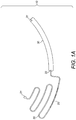
- Figure 1A illustrates a microfluidic device (10) which comprises the following main fluidic structure: a sample inlet (21), a connection conduit (20) and a detection chamber (30).
- the loaded blood sample flows from the sample inlet (21) through the connection conduit (20) by means of capillary or pressure driven flow.
- the shape and length of the connection conduit (20) may be arranged in such a manner that enables space saving within the device, using a meandering configuration.
- connection conduit (20) is provided within a single plane of the device (10) (one example is a serpentine shape as depicted in Fig. 1A ). It will be appreciated that although a planar serpentine shape is depicted in Figure 1A , any shape suitable for providing a substantially planar trajectory of the blood flow within the device could be provided. It should be noted that sharp angles within the projected trajectory should be avoided to reduce impediments to sample flow and to prevent trapping of air bubbles inside the connection conduit (20) whilst the chamber is filing with the blood sample. This is particular preferably where the blood flow is capillary driven.
- the blood sample exits the connection conduit (20) through a defined outlet (22) as illustrated in Figure 1A .
- the blood sample then proceeds by filling the detection chamber (30); wherein preferably, the detection chamber (30) comprises a vent (31) for air escape.
- the detection chamber (30) comprises two planar and transparent surfaces suitable for optical imaging. It will be appreciated that although the depicted detection chamber (31) in both Figures 1 and 2 comprises two planar, transparent surfaces, alternative arrangements which allow for optical imaging may be provided.
- the height of the detection chamber (30) may be set to be no greater than 30 ⁇ m so that a single layer of blood cells is accommodated within it to facilitate cell counting. However, the height of the detection chamber (30) is not restricted to this height.
- the device (10) may result from two halves containing microfluidic structures. These may be assembled together by any suitable means, for example using a bonding technique.
- the connection conduit (20) Prior to assembly, the connection conduit (20) may be adapted to store dry reagents at particular positions therein.
- the dry reagents will preferably be prepared outside of the device (10) in a volatile solution at a given concentration. The precise amounts and concentration of reagent will depend on the solubility of the reagent.
- a predefined volume of the solution will then be dispensed at a given position of the connection conduit (20).
- the reagent will then be deposited within the wetted area (23) of the connection conduit (20) as illustrated in Figure 1A . This procedure may be repeated as many times as necessary depending on the desired amount of reagent for dry storage.
- the volume and surface tension of the loaded solutions is preferably chosen to allow for a proper filling and confinement within the connection conduit (20) so that a well-defined patch of dry reagents with a predefined length can be placed in a well defined position within the connection conduit (20).
- the connection conduit (20) accommodates at least two types of dry reagents; for example a haemolytic agent and a staining agent.
- the role of the haemolytic agent is to selectively lyse erythrocytes from the blood sample before the detection chamber (30) is completely filled. By avoiding having erythrocytes present in the detection chamber (30) when it is filled with the processed blood sample, misinterpretation caused by leukocytes counts and posterior classification is reduced.
- a staining agent from the family of hematoxylin and cosin (H&E) stains, Romanowsky stains, methacromatic stains or any combination thereof can be used for differential staining of leukocytes. From combinations of colour information with morphological features like granularity, size, shape of the cell cytoplasm and nucleus, it is possible to obtain a portfolio of distinct signatures for each of the sub-populations under study.
- H&E hematoxylin and cosin
- the stabilizing agent may be of the family of aldheyde-based fixatives, picric acid-based fixatives and polyoxythylene-polyoxypropylene block copolymers and may be included as a dry reagent in the connection conduit (20). Such stabilizers are used to preserve and impart robustness to the leukocyte membrane and overall cell structure.
- a surfactant also be included as a dry reagent in the connection conduit (20) in some embodiments.
- the surfactant may be used to decrease the surface tension between the blood sample and the inner walls of the connection conduit (20).
- Other properties of surfactants such as its use as a dispersant, detergent and emulsifier may also be useful to improve the reaction between the blood sample and the dry reagents.
- connection conduit (20) As illustrated in Figure 1B , while filling the connection conduit (20) from the inlet, the blood volume (25) encounters a series of patches of dry reagents (26, 27, 28). Although in Figure 1B three patches of dry reagents are provided, it will be appreciated that any number (one or more) patches may be provided within the connection conduit (20). As the blood sample flows over the one or more patches, it will wash and dissolve the reagent(s) which will gradually diffuse through the blood volume and prompt a chemical reaction. The dynamics of such reactions depends mainly on the blood flow rate and the length of the patch of dry reagent. The content of dry reagent stored in the connection conduit (20) and how easily it dissolves on blood will also have an effect on the dynamics.
- the front of the flowing blood which reaches the dry chemical patch first is more likely to wash a greater extent of the dry reagent depending on its solubility and the presence of surfactants in the system. Consequently, the concentration of a dissolved dry reagent along the blood volume in the direction opposite to the flow is expected to decrease.
- the concentration of the dissolved dry reagent is expected to homogenize faster.
- the volume of the detection chamber (30) may preferably be designed to match a predefined fraction of the volume comprised by the connection conduit (20) to ensure that within said fraction the processed blood exhibits characteristics which are as homogeneous as possible.
- connection conduit (20) Furthermore, depending on how many reactions are meant to occur throughout the connection conduit (20), it will be appreciated that the number of patches, the chemical composition of their respective dry content, the blood flow rate and/or the connection conduit (20) volumetry can be adjusted to suit the particular application.
- An advantage of separating the at least one reaction site (26, 27, 28) from the detection chamber (30) where optical based detection of the processed sample occurs is that the area and height of the detection chamber (30) can be independently adjusted for proper detection of the stained leukocytes and further traces of the dry reagents involved in the serial reactions can be excluded from the field of view; for example avoided precipitates of the stain under use in the field of view.
- the height of the detection chamber (30) may be set so as to contain one layer of stained leukocytes and an area to accommodate sufficient processed blood volume to provide a significant statistical count of each leukocyte sub-population.
- a device for simultaneous measurement of partial or total leukocyte counts and haematocrit estimation and blood plasma extraction for further analytical purposes is disclosed.
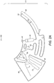
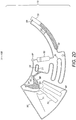
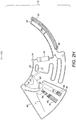
- the following microfluidic device comprises the main fluidic structures as represented in Figure 2A : sample inlet chamber (21); connection conduit (20); detection chamber (30); waste chamber (50); metering chamber (60); downstream chamber (70); overflow chamber (80); network of air channels (90); flow barriers valves (61, 62, 63) and siphon (71).
- the network of air channels (90) assists with air exchange between all fluidic structures being filled with or emptied of the loaded blood sample, to provide a substantially even air pressure distribution in the device (10).
- the design of the microfluidic structures and their operation prevent sample ingress into the air channel network (90); otherwise under and overpressure regions may arise in the device (10) thereby compromising its fluidic functions.
- the device (10) can be operated in two fluidic regimes: capillary driven flow and centrifugal pressure driven flow. Accordingly, the device may be designed to be rotatable about an axis of revolution (100) as illustrated in Figure 2A to drive fluid flow by centrifugation.
- All the fluidic structures described herein may be designed in polar coordinates relative to said axis of revolution (100). Consequently, all structures may be characterized by their radial and angular dimensions and positioning in respect of the axis of revolution (100). Upon rotation of the device (10) around the axis of revolution (100), a liquid sample in the device (10) experiences a centrifugal field.
- Different volumes of a loaded blood sample may be metered and fractionated in independent aliquots for further independent processing.
- said blood aliquots have the same constitution and are representative of the loaded blood sample. Due to its complex biological composition, when a blood sample is exposed to a centrifugal field its components will redistribute themselves within the blood volume based on their densities, thereby jeopardizing the original homogeneity of the sample.
- the device (10) described herein and illustrated in Figure 2 seeks to overcome or mitigate this issue.
- the device (10) before loading the blood sample, the device (10) is exposed to atmospheric pressure through the open air vent (91) which is included in the integrated air channels network (90) which connects the fluidic modules listed above.
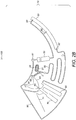
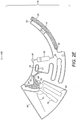
- the inlet chamber or sample inlet (21) comprises an opening (24) connecting the inlet chamber (21) to the exterior of the device (10). Once the sample is loaded into said opening (24), it moves into the inlet chamber (21) solely by capillary action and starts filling the chamber (21) towards the metering chamber (60) and connection conduit (20) simultaneously as is illustrated in the hatched section (2) in Figure 2B .
- the metering chamber (60) substantially fills completely up to a predefined volume of the loaded blood sample.
- the metering chamber (60) is preferably shaped so to avoid entrapment of air bubbles while filling by capillary action as is illustrated in the hatched section (4) in Figure 2C .
- One or more flow barriers valves are placed in the metering chamber (60) to connect the metering chamber (60) to the surrounding fluidic modules to ensure that the blood sample does not flow through the barrier valves by capillarity.
- the flow barrier valves (61, 62) are connected to the air channel network (90) to prevent clogging and ensure air release from the metering chamber (60) to the outside of the device (10).
- Providing an air release during capillary filling from one or more points of the metering chamber (60) enables complete filling of the chamber (60).
- dried anticoagulant are additionally added to the metering chamber (60) to avoid undesirable clotting of the metered blood sample, in some embodiments.
- connection conduit 20 Once the blood sample reaches the connection conduit 20 it fills it by capillarity as illustrated in the hatched section (6) of Figure 2C .
- the chemical reactions operating on the blood whilst the blood sample is flowing over the dry chemical patches (26, 27, 28) comprised in the connection conduit (20) are as described above with respect to Figure 1 .
- the blood sample Once the blood sample enters the detection chamber (30) by capillary, it has preferably already reacted with the erythrocyte lytic agent and differential stains for leukocytes.
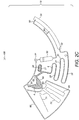
- the detection chamber (30) may include at least one connection to the integrated air channel network (90). Although two connections (92, 93) are illustrated in Figure 2C , it will be appreciated that any number of connections may be provided.
- each connecting air channel may include a flow barrier valve to prevent the processed blood volume from entering the air channels by capillarity.
- the air channels connect the detection chamber (30) to a waste chamber (50) located radially inwards on the device (10) relative to the axis of revolution (100). The role of the waste chamber (50) will be described in more detail below.
- the device (10) may be placed in an instrument comprising a microscopy assembly and a transport mechanism.
- the microscopy assembly (10) may include a lens, a focusing mechanism and a digital camera.
- the transport mechanism allows angular positioning of the device (10) to be controlled.
- a positioning sensor may be used to assist the precise alignment of one of the extremities of the detection chamber (30) with the microscopy assembly which may then be followed by incremental angular displacements defining a series of positions within the detection chamber (30). At each position a focused picture of the processed blood sample may be taken with a given magnification.
- a precise radial positioning mechanism can be coupled to the device (10) for radial scanning of the detection chamber (30).
- the device (10) may also be immobilized or slowly rotating for discrete positioning purposes and all fluidic functions may be accomplished by capillary based handling of the blood sample without further interference/assistance.
- the device (10) is preferably operated in centrifugal based flow. At this point the opening of the inlet chamber (21) and air vent escape (91) may be sealed and future blood sample and air exchanges occur exclusively inside the device (10). Once the device (10) starts rotating at a given angular velocity about the axis of rotation (100), the blood volume comprised in it experiences a centrifugal force pointing towards the outward radius forcing the blood sample to flow. The same instrument is used, in some embodiments, during the capillary flow, image acquisition and centrifugal flow phases.
- the metering chamber (60) in some embodiments, includes a split feature (64) between the metering chamber (60) and the inlet chamber (21).
- the split feature (64) may be characterized by a narrower passage between metering (60) and inlet chambers (21) and preferably has a cuspidal like shape with a rounded edge.
- a flow barrier valve (62) is preferably provided which is connected to the air channel network (90) and may be aligned with the split feature (64) to prevent blockage and enable air ingestion which is needed for the blood sample split event as represented in Figure 2F .
- the continuum of blood previously filling the device (10) will consequently divide into two independent fractions: the volume contained in the metering chamber (60) and the volume comprised in the inlet (21), connection conduit (20) and detection chamber (30) as illustrated by hatched sections (14) and (16) of Figure 2F , respectively.
- the previous microfluidic architecture can be replicated in a series of n metering chambers (60) and n - 1 split points between them to obtain n aliquots with predefined volumes from an initial blood sample.
- the metering chamber (60) comprises at least one flow barrier valve (63) as illustrated in Figure 2F , which connects the metering chamber (60) to a downstream chamber (70) and is located radially outwards with respect to the revolution axis (100).
- the flow barrier valve (63) brakes given that the centrifugal force exerted on the metered blood volume is enough to overcome the surface tension barrier the valve (63) poses towards blood flowing through it.
- the braking events occurring at the split feature (64) embodied in the metering chamber (60) and the flow barrier valve (63) connecting the metering chamber (60) to the downstream chamber (70) is preferably synchronized for a correct fractionation of the blood volume enclosed in the metering chamber (60).
- the metering chamber (60) is adapted to supply a substantially continuous stream of blood flowing from the flow barrier valve (63) into the downstream chamber (70) until it is substantially empty of blood, as is illustrated by grey out section (18) of Figure 2F .
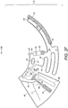
- a stream of blood starts filling the outwardly radial positions of the downstream chamber (70) whilst the blood meniscus in said chamber (70) rises radially inwards until it reaches the connection (81) between the downstream (70) and overflow (80) chambers.
- a blood stream occupies the full height of the downstream chamber (70) as the downstream chamber is filled and consequently defines two fluidically separate areas extending from each side of the stream: 1) part of the downstream chamber (70) on the side of the siphon (71) and 2) its remaining volume plus the overflow chamber (80). Each of those areas is preferably connected to the air channel network (90) by one or more connections.
- two connections (92, 93) may be provided for air release while filling of the downstream chamber (70). This advantageously prevents overpressure which can arise within said areas. Overpressure can exert a deflecting force on the blood stream thereby risking incorrect filling of the downstream chamber (70).
- connection (81) between the downstream chamber (70) and the overflow chamber (80) is designed to transfer liquid in excess of a pre-defined volume enclosed in the downstream chamber (70) to the overflow chamber (80), which is preferably smaller than the metered blood volume, so that the overflow chamber (80) is partially filled with blood.
- the metered blood sample is actuated by the centrifugal force as described above and consequently the erythrocytes contained in the sample will start to sediment.
- the device (10) is in some embodiments kept rotating for further sedimentation towards the outwardly radial positions of those chambers (70, 80).
- two respective erythrocyte depleted and enriched phases gradually appear on the blood volumes contained in the downstream (70) and overflow chambers (80) as is illustrated by hatched sections (32, 33) with respect to the downstream chamber (70) and hatched sections (34, 35) with respect to the overflow chamber (80), respectively.
- Haematocrit calculation is, in some embodiments, done by combining the measurements of both downstream (70) and overflow (80) chambers.
- the design of these chambers (70, 80), the rotation velocity of the device (10) and the rotation time are likely to influence both sedimentation and haematocrit measurements. It is important to note that until filling of the downstream (70) and overflow chambers (80) is substantially completed, the two phase separation of the flowing blood sample due to sedimentation already occurs. This implies that when the blood sample reaches the overflow level of the downstream chamber (70), the blood volume that flows towards the overflow chamber (80) is likely to be partially depleted from erythrocytes.
- haematocrit measurements on the downstream (70) and overflow (80) chambers reveal higher and lower haematocrit results, respectively. This is why haematocrit measurements on both chambers (70, 80) is preferable as it is likely to lead to a more accurate result.
- the haematocrit influences the erythrocyte sedimentation velocity measurements; the lower the haematocrit, the faster the sedimentation mechanism occurs.
- the measured sedimentation velocity is preferably corrected to account for such bias.
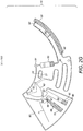
- the downstream chamber (70) may also include a siphon for cell free plasma (71) extraction once the erythrocyte sedimentation and haematocrit measurement are completed, as illustrated in Figure 2I .
- a siphon for cell free plasma (71) extraction once the erythrocyte sedimentation and haematocrit measurement are completed, as illustrated in Figure 2I .
- the siphon level is reached when the meniscus reaches the inlet level which is indicated by feature (81). This transition between the downstream chamber (70) and the overflow the chamber (80) is defined by a precise radial distance relative to the axis of revolution (100).
- the siphon crest (79) is located radially inwards relative to the equilibrium radius; and 2) the centrifugal force acting on the blood volume contained in the siphon (71) overcomes the capillary force exerted on said blood volume which has the opposite direction of the centrifugal force in the siphon branch (77) comprised between its inlet (78) and crest (79).
- the device (10) stops rotating or rotates at a lower angular velocity such that the capillary force overcomes the centrifugal force, the blood volume progresses through the siphon (71) until priming is completed. It is preferable that the radial position of the blood volume inside the siphon (71) reaches a position in outer radius (79a) compared to the radius of the siphon inlet (78). At this point, the device (10) starts rotating and the cell free plasma comprised between the top of the downstream chamber (70) and the inlet (78) of the siphon (71) starts draining through the siphon (71).
- the described preferable procedure ensures aliquoting of a precise volume of blood plasma given that said volume can be easily tuned by proper dimensioning of the downstream chamber (70) and location of the siphon inlet (78) in respect of the downstream chamber (70).
- the siphon inlet (78) is preferably located above, or radially inwards, from the plasma-erythrocytes phase transition. Since such transition depends on the blood sample haematocrit, the siphon inlet (78) may be positioned for a sample with a haematocrit of up to 65% which is a value far above the maximum values found in practice.
- the aliquoted plasma volume can be further processed and used for additional testing.
- the meniscus defining the ends of blood volume preferably levels itself at the same radius to maintain the hydrostatic pressure independently of the shape and volume of the reservoirs filled in between, as illustrated by features (41) and (42) of Figure 2F .
- the fluidic structures are designed to ensure that the blood meniscus rises in the waste chamber (50) until it equilibrates with the meniscus on the other extreme of the blood fraction, which occurs below the split feature (64); i.e. on the outer radius relative to the axis of revolution (100).
- the radial position of the equilibrium of both meniscuses depends on the volume of the channels and reservoirs comprising the said blood.
- This equilibrium radius preferably occurs below the surface tension barrier (52) disposed in the waste chamber (50).
- This barrier (52) ensures that once the microfluidic disc stops rotating, the blood in the waste reservoir (50) does not reach the air channels network (90) by capillary flow through channel (94), as illustrated in Figure 2F .
- the device (10) as illustrated in Figure 2A is provided as a cartridge.
- the cartridge in some embodiment resembles a CD/DVD configuration constituted by two transparent and planar circular halves brought together by an intermediate adhesive layer.
- the halves are preferably engraved with the microfluidic structures and openings to the exterior described above, with the exception of the detection chamber (30) which is cut out from the adhesive layer.
- the three parts may be assembled and bonded to form a self-contained cartridge.
- connection conduit (20) is 30 mm long, 0.6 mm wide and 0.2 mm deep.
- This connection conduit (20) was tested for a series of 3 sequential reactions, comprising a first reaction site which was 10 mm long which comprised glutaraldheyde as a stabilizer agent, a 10 mm long reaction site with a mixture of surfactant and lytic agent (Surfynol and saponine, respectively) and a 10 mm long reaction site with a mixture of stains.
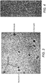
- the mixture of stains included a mixture of eosin, methylene blue and basic orange 21 leading to differential colours for a 5-part classification of leukocytes: lymphocytes stain blue, monocytes stain blue/purple, neutrophils exhibit blue nucleus and pale yellow cytoplasm, eosinophils exhibit blue nucleus and dark yellow granules, basophils stain bright pink.
- lymphocytes stain blue lymphocytes stain blue
- monocytes stain blue/purple neutrophils exhibit blue nucleus and pale yellow cytoplasm
- eosinophils exhibit blue nucleus and dark yellow granules
- basophils stain bright pink It will be appreciated that other known reagents and combinations thereof may be used in the device. It will also be appreciated that the reagents may be arranged having different dimensions in the connection conduit (20).
- connection conduit (20) 3.6 ⁇ L
- detection chamber (30) was designed to retain 1 ⁇ L of that volume.
- the detection chamber (30) in this example has a height of 20 ⁇ m to accommodate one single layer of cells.
- Figure 3 represents an image obtained with several stained leukocytes from this example. It will be appreciated that the dimensions of the connection conduit and detection chamber may be adjusted.
- the metering (6) and downstream (70) chambers were designed in this example to accommodate 5 uL and 4 uL, respectively.
- a 1 uL cell free plasma was drained from the downstream chamber (70) through the siphon (71).
- Embodiments of the device described herein are capable of determining both partial leukocyte counts and a haematocrit fraction of blood.
- the embodiments described above are adapted for the processing of a blood sample, at least some of the above embodiments are suitable for processing any liquid sample, for example any liquid to be reacted with one or more reagents prior to imaging. Indeed, the described re-suspension and other liquid handling mechanisms and structures are equally applicable to applications that do not involve imaging, for example, where the use of reagents is required on its own or in connection with other detection mechanisms.
- a flow barrier valve refers to a connection conduit incorporating a surface tension barrier to provide an impediment to capillary driven flow.
- the surface tension barrier can be provided by any suitable arrangement, for example a suddent expansion or other geometrical design, or a surface treatment of all or a portion of the conduit.
Landscapes
- Health & Medical Sciences (AREA)
- Chemical & Material Sciences (AREA)
- Life Sciences & Earth Sciences (AREA)
- Physics & Mathematics (AREA)
- General Health & Medical Sciences (AREA)
- Analytical Chemistry (AREA)
- Pathology (AREA)
- Immunology (AREA)
- General Physics & Mathematics (AREA)
- Biochemistry (AREA)
- Engineering & Computer Science (AREA)
- Dispersion Chemistry (AREA)
- Hematology (AREA)
- Biomedical Technology (AREA)
- Molecular Biology (AREA)
- Medicinal Chemistry (AREA)
- Biophysics (AREA)
- Food Science & Technology (AREA)
- Ecology (AREA)
- Urology & Nephrology (AREA)
- Clinical Laboratory Science (AREA)
- Chemical Kinetics & Catalysis (AREA)
- Signal Processing (AREA)
- Investigating Or Analysing Biological Materials (AREA)
- Computer Vision & Pattern Recognition (AREA)
- Automatic Analysis And Handling Materials Therefor (AREA)
- Investigating Or Analysing Materials By Optical Means (AREA)
Applications Claiming Priority (2)
| Application Number | Priority Date | Filing Date | Title |
|---|---|---|---|
| PT10620312 | 2012-03-12 | ||
| PCT/EP2013/055020 WO2013135713A1 (en) | 2012-03-12 | 2013-03-12 | Liquid sample imaging device and method |
Publications (2)
| Publication Number | Publication Date |
|---|---|
| EP2825881A1 EP2825881A1 (en) | 2015-01-21 |
| EP2825881B1 true EP2825881B1 (en) | 2018-05-30 |
Family
ID=47844389
Family Applications (1)
| Application Number | Title | Priority Date | Filing Date |
|---|---|---|---|
| EP13708496.8A Active EP2825881B1 (en) | 2012-03-12 | 2013-03-12 | Liquid sample imaging device and method |
Country Status (4)
| Country | Link |
|---|---|
| US (1) | US9914120B2 (enExample) |
| EP (1) | EP2825881B1 (enExample) |
| JP (1) | JP6335802B2 (enExample) |
| WO (1) | WO2013135713A1 (enExample) |
Families Citing this family (22)
| Publication number | Priority date | Publication date | Assignee | Title |
|---|---|---|---|---|
| GB201014805D0 (en) | 2010-09-07 | 2010-10-20 | Multi Sense Technologies Ltd | Microfluidics based assay device |
| DE102012202775B4 (de) * | 2012-02-23 | 2016-08-25 | Hahn-Schickard-Gesellschaft für angewandte Forschung e.V. | Fluidikmodul, vorrichtung und verfahren zum pumpen einer flüssigkeit |
| WO2016050755A2 (en) | 2014-09-29 | 2016-04-07 | Biosurfit S.A. | Cell counting |
| WO2016050753A1 (en) * | 2014-09-29 | 2016-04-07 | Biosurfit S.A. | Microfluidic vent structure |
| EP3201625A1 (en) | 2014-09-29 | 2017-08-09 | Biosurfit, S.A. | Positioning mechanism |
| US10519493B2 (en) | 2015-06-22 | 2019-12-31 | Fluxergy, Llc | Apparatus and method for image analysis of a fluid sample undergoing a polymerase chain reaction (PCR) |
| US10214772B2 (en) | 2015-06-22 | 2019-02-26 | Fluxergy, Llc | Test card for assay and method of manufacturing same |
| US11371091B2 (en) | 2015-06-22 | 2022-06-28 | Fluxergy, Inc. | Device for analyzing a fluid sample and use of test card with same |
| CN106056612B (zh) * | 2016-06-03 | 2019-01-11 | 盈开生物科技(上海)有限公司 | 血液分层识别方法 |
| GB201611442D0 (en) | 2016-06-30 | 2016-08-17 | Lumiradx Tech Ltd | Fluid control |
| JP6799308B2 (ja) * | 2016-09-30 | 2020-12-16 | 株式会社アイビー | 液体試料搬送方法および試薬チップ |
| US20200238279A1 (en) * | 2017-03-08 | 2020-07-30 | Northwestern University | Devices, systems, and methods for specimen preparation and analysis using capillary and centrifugal forces |
| US11287404B2 (en) * | 2017-12-21 | 2022-03-29 | International Business Machines Corporation | Analysis apparatus with spectrometer |
| US11291997B2 (en) * | 2018-08-02 | 2022-04-05 | Colorado State University Research Foundation | Rotary manifold for paper-based immunoassays |
| EP3840635A4 (en) * | 2018-08-23 | 2022-05-18 | Sanwa Biotech Ltd. | PORTABLE DIAGNOSTIC APPARATUS AND RELATED METHOD |
| JP7066043B2 (ja) | 2018-09-11 | 2022-05-12 | エフ.ホフマン-ラ ロシュ アーゲー | 液体パックを備えたカートリッジ |
| EP3742174A4 (en) * | 2019-04-04 | 2022-01-12 | Biobank Inc. | MULTIPLE SYSTEM FOR SIMULTANEOUSLY PERFORMING A BIOCHEMICAL TEST AND BLOOD ANALYSIS, AND MULTIPLE DISC USED FOR THIS PURPOSE |
| KR102259432B1 (ko) * | 2019-04-04 | 2021-06-02 | 바이오뱅크 주식회사 | 생화학검사와 혈액검사를 동시에 수행하는 멀티시스템 및 이에 사용되는 멀티디스크 |
| TWI777177B (zh) * | 2020-06-16 | 2022-09-11 | 逢甲大學 | 離心式純化平台及其使用方法 |
| CN113959819B (zh) * | 2020-11-13 | 2025-01-07 | 深圳安侣医学科技有限公司 | 一体化试剂盒 |
| CN116026746A (zh) * | 2021-10-27 | 2023-04-28 | 深圳市理邦精密仪器股份有限公司 | 白细胞的数量检测方法和血细胞分析仪 |
| GB2616668A (en) * | 2022-03-18 | 2023-09-20 | Entia Ltd | A method of obtaining an image of a biological sample in a cuvette |
Family Cites Families (24)
| Publication number | Priority date | Publication date | Assignee | Title |
|---|---|---|---|---|
| US7138254B2 (en) * | 1999-08-02 | 2006-11-21 | Ge Healthcare (Sv) Corp. | Methods and apparatus for performing submicroliter reactions with nucleic acids or proteins |
| US20020076354A1 (en) * | 2000-12-01 | 2002-06-20 | Cohen David Samuel | Apparatus and methods for separating components of particulate suspension |
| US7041068B2 (en) * | 2001-06-12 | 2006-05-09 | Pelikan Technologies, Inc. | Sampling module device and method |
| AU2003232169B8 (en) | 2002-06-11 | 2008-05-08 | Koninklijke Philips Electronics N.V. | A disposable cartridge for characterizing particles suspended in a liquid |
| WO2005088300A1 (en) * | 2004-03-16 | 2005-09-22 | Fuji Photo Film Co., Ltd. | Assay chip |
| JP5122967B2 (ja) | 2004-10-20 | 2013-01-16 | コーニンクレッカ フィリップス エレクトロニクス エヌ ヴィ | 血液サンプル中の異なる種類の血液細胞の同時計数のための溶解試薬 |
| WO2006070772A1 (en) | 2004-12-28 | 2006-07-06 | Matsushita Electric Industrial Co., Ltd. | Testing device and blood mixing and diluting method |
| CA2597496A1 (en) | 2005-02-10 | 2006-08-17 | Chempaq A/S | Dual sample cartridge and method for characterizing particles in liquid |
| US20100291588A1 (en) * | 2005-06-24 | 2010-11-18 | The Board Of Regents Of The University Of Texas System | Systems and methods including self-contained cartridges with detection systems and fluid delivery systems |
| KR101284072B1 (ko) * | 2005-10-18 | 2013-07-10 | 후지모리 고교 가부시키가이샤 | 혈전 관측 장치 및 혈전 관측 방법 |
| JP4901333B2 (ja) * | 2006-06-30 | 2012-03-21 | ローム株式会社 | マイクロチップ検査装置 |
| US8169600B2 (en) * | 2006-09-15 | 2012-05-01 | Arryx, Inc. | Surface mapping by optical manipulation of particles in relation to a functionalized surface |
| US7738094B2 (en) * | 2007-01-26 | 2010-06-15 | Becton, Dickinson And Company | Method, system, and compositions for cell counting and analysis |
| EP2040073A1 (en) * | 2007-09-20 | 2009-03-25 | Iline Microsystems, S.L. | Microfluidic device and method for fluid clotting time determination |
| CA2706646A1 (en) * | 2007-11-26 | 2009-06-04 | Fujimori Kogyo Co., Ltd. | Microchip and blood monitoring device |
| SE532499C2 (sv) * | 2008-01-18 | 2010-02-09 | Hemocue Ab | Metod och apparat för analys av partiklar i ett vätskeformigt prov |
| EP2133149A1 (en) * | 2008-06-13 | 2009-12-16 | F.Hoffmann-La Roche Ag | Lab-on-disc device |
| EP2419217B1 (en) | 2009-04-13 | 2014-11-12 | Micronics, Inc. | Microfluidic clinical analyzer |
| CN102740976B (zh) * | 2010-01-29 | 2016-04-20 | 精密公司 | 取样-应答微流体盒 |
| GB2479139A (en) | 2010-03-29 | 2011-10-05 | Biosurfit Sa | A liquid distribution and metering device |
| US8741235B2 (en) * | 2011-12-27 | 2014-06-03 | Honeywell International Inc. | Two step sample loading of a fluid analysis cartridge |
| US9063121B2 (en) * | 2012-05-09 | 2015-06-23 | Stat-Diagnostica & Innovation, S.L. | Plurality of reaction chambers in a test cartridge |
| GB201217390D0 (en) * | 2012-09-28 | 2012-11-14 | Agplus Diagnostics Ltd | Test device and sample carrier |
| GB2516672B (en) * | 2013-07-29 | 2015-05-20 | Atlas Genetics Ltd | A system and method for expelling liquid from a fluidic cartridge |
-
2013
- 2013-03-12 WO PCT/EP2013/055020 patent/WO2013135713A1/en not_active Ceased
- 2013-03-12 EP EP13708496.8A patent/EP2825881B1/en active Active
- 2013-03-12 JP JP2014561423A patent/JP6335802B2/ja not_active Expired - Fee Related
- 2013-03-12 US US14/384,200 patent/US9914120B2/en not_active Expired - Fee Related
Also Published As
| Publication number | Publication date |
|---|---|
| JP2015510134A (ja) | 2015-04-02 |
| WO2013135713A1 (en) | 2013-09-19 |
| US20150024426A1 (en) | 2015-01-22 |
| JP6335802B2 (ja) | 2018-05-30 |
| EP2825881A1 (en) | 2015-01-21 |
| US9914120B2 (en) | 2018-03-13 |
Similar Documents
| Publication | Publication Date | Title |
|---|---|---|
| EP2825881B1 (en) | Liquid sample imaging device and method | |
| US11478789B2 (en) | Automated microscopic cell analysis | |
| EP1069951B1 (en) | Disposable apparatus for performing blood cell counts | |
| US9199233B2 (en) | Biologic fluid analysis cartridge with deflecting top panel | |
| US8980635B2 (en) | Disposable cartridge for fluid analysis | |
| US20040019300A1 (en) | Microfluidic blood sample separations | |
| US11933701B2 (en) | Devices and methods for sample analysis with serial dilution | |
| US20080257754A1 (en) | Method and apparatus for entry of specimens into a microfluidic device | |
| US20040265172A1 (en) | Method and apparatus for entry and storage of specimens into a microfluidic device | |
| WO2009131677A1 (en) | Flow control in microfluidic systems | |
| US10641698B2 (en) | Methods for complete blood count measurement | |
| US11433395B2 (en) | Separating apparatus, separating method, separating device, inspection apparatus, and inspection method | |
| Ashiba et al. | Microfluidic chips for forward blood typing performed with a multichannel waveguide-mode sensor | |
| CA2713532C (en) | Separation chip and separation method | |
| US11305236B2 (en) | Surface tension driven filtration | |
| US20210170410A1 (en) | Devices, systems, and methods for specimen preparation using capillary and centrifugal forces | |
| Oksuz et al. | Dynamic fluidic manipulation in microfluidic chips with dead-end channels through spinning: the Spinochip technology for hematocrit measurement, white blood cell counting and plasma separation | |
| US20060204403A1 (en) | Micro-fluidic fluid separation device and method | |
| Ducrée | Centrifugal microfluidics | |
| Pishbin et al. | A centrifugal microfluidic platform for determination of blood hematocrit level | |
| Brenner | Polymer fabrication and microfluidic unit operations for medical diagnostics on a rotating disk | |
| Hosseinkhannazer et al. | Two-species microparticle detection in optofluidic biochips with polymeric waveguides | |
| US10307756B2 (en) | Capillary junction | |
| KR20250171297A (ko) | 미세유체 샘플 핸들링 | |
| Ashiba et al. | ÔØ Å ÒÙ× Ö ÔØ |
Legal Events
| Date | Code | Title | Description |
|---|---|---|---|
| PUAI | Public reference made under article 153(3) epc to a published international application that has entered the european phase |
Free format text: ORIGINAL CODE: 0009012 |
|
| 17P | Request for examination filed |
Effective date: 20140929 |
|
| AK | Designated contracting states |
Kind code of ref document: A1 Designated state(s): AL AT BE BG CH CY CZ DE DK EE ES FI FR GB GR HR HU IE IS IT LI LT LU LV MC MK MT NL NO PL PT RO RS SE SI SK SM TR |
|
| AX | Request for extension of the european patent |
Extension state: BA ME |
|
| DAX | Request for extension of the european patent (deleted) | ||
| 111Z | Information provided on other rights and legal means of execution |
Free format text: AL AT BE BG CH CY CZ DE DK EE ES FI FR GB GR HR HU IE IS IT LT LU LV MC MK MT NL NO PL PT RO RS SE SI SK SM TR Effective date: 20160224 |
|
| STAA | Information on the status of an ep patent application or granted ep patent |
Free format text: STATUS: EXAMINATION IS IN PROGRESS |
|
| 17Q | First examination report despatched |
Effective date: 20170814 |
|
| RAP1 | Party data changed (applicant data changed or rights of an application transferred) |
Owner name: BIOSURFIT, S.A. |
|
| GRAP | Despatch of communication of intention to grant a patent |
Free format text: ORIGINAL CODE: EPIDOSNIGR1 |
|
| STAA | Information on the status of an ep patent application or granted ep patent |
Free format text: STATUS: GRANT OF PATENT IS INTENDED |
|
| INTG | Intention to grant announced |
Effective date: 20180301 |
|
| GRAJ | Information related to disapproval of communication of intention to grant by the applicant or resumption of examination proceedings by the epo deleted |
Free format text: ORIGINAL CODE: EPIDOSDIGR1 |
|
| STAA | Information on the status of an ep patent application or granted ep patent |
Free format text: STATUS: EXAMINATION IS IN PROGRESS |
|
| GRAR | Information related to intention to grant a patent recorded |
Free format text: ORIGINAL CODE: EPIDOSNIGR71 |
|
| GRAS | Grant fee paid |
Free format text: ORIGINAL CODE: EPIDOSNIGR3 |
|
| STAA | Information on the status of an ep patent application or granted ep patent |
Free format text: STATUS: GRANT OF PATENT IS INTENDED |
|
| GRAA | (expected) grant |
Free format text: ORIGINAL CODE: 0009210 |
|
| STAA | Information on the status of an ep patent application or granted ep patent |
Free format text: STATUS: THE PATENT HAS BEEN GRANTED |
|
| INTC | Intention to grant announced (deleted) | ||
| AK | Designated contracting states |
Kind code of ref document: B1 Designated state(s): AL AT BE BG CH CY CZ DE DK EE ES FI FR GB GR HR HU IE IS IT LI LT LU LV MC MK MT NL NO PL PT RO RS SE SI SK SM TR |
|
| INTG | Intention to grant announced |
Effective date: 20180424 |
|
| REG | Reference to a national code |
Ref country code: GB Ref legal event code: FG4D |
|
| REG | Reference to a national code |
Ref country code: CH Ref legal event code: EP |
|
| REG | Reference to a national code |
Ref country code: AT Ref legal event code: REF Ref document number: 1004143 Country of ref document: AT Kind code of ref document: T Effective date: 20180615 |
|
| REG | Reference to a national code |
Ref country code: IE Ref legal event code: FG4D |
|
| REG | Reference to a national code |
Ref country code: DE Ref legal event code: R096 Ref document number: 602013038110 Country of ref document: DE |
|
| REG | Reference to a national code |
Ref country code: NL Ref legal event code: FP |
|
| REG | Reference to a national code |
Ref country code: LT Ref legal event code: MG4D |
|
| PG25 | Lapsed in a contracting state [announced via postgrant information from national office to epo] |
Ref country code: ES Free format text: LAPSE BECAUSE OF FAILURE TO SUBMIT A TRANSLATION OF THE DESCRIPTION OR TO PAY THE FEE WITHIN THE PRESCRIBED TIME-LIMIT Effective date: 20180530 Ref country code: SE Free format text: LAPSE BECAUSE OF FAILURE TO SUBMIT A TRANSLATION OF THE DESCRIPTION OR TO PAY THE FEE WITHIN THE PRESCRIBED TIME-LIMIT Effective date: 20180530 Ref country code: CY Free format text: LAPSE BECAUSE OF FAILURE TO SUBMIT A TRANSLATION OF THE DESCRIPTION OR TO PAY THE FEE WITHIN THE PRESCRIBED TIME-LIMIT Effective date: 20180530 Ref country code: BG Free format text: LAPSE BECAUSE OF FAILURE TO SUBMIT A TRANSLATION OF THE DESCRIPTION OR TO PAY THE FEE WITHIN THE PRESCRIBED TIME-LIMIT Effective date: 20180830 Ref country code: FI Free format text: LAPSE BECAUSE OF FAILURE TO SUBMIT A TRANSLATION OF THE DESCRIPTION OR TO PAY THE FEE WITHIN THE PRESCRIBED TIME-LIMIT Effective date: 20180530 Ref country code: NO Free format text: LAPSE BECAUSE OF FAILURE TO SUBMIT A TRANSLATION OF THE DESCRIPTION OR TO PAY THE FEE WITHIN THE PRESCRIBED TIME-LIMIT Effective date: 20180830 Ref country code: LT Free format text: LAPSE BECAUSE OF FAILURE TO SUBMIT A TRANSLATION OF THE DESCRIPTION OR TO PAY THE FEE WITHIN THE PRESCRIBED TIME-LIMIT Effective date: 20180530 |
|
| PG25 | Lapsed in a contracting state [announced via postgrant information from national office to epo] |
Ref country code: GR Free format text: LAPSE BECAUSE OF FAILURE TO SUBMIT A TRANSLATION OF THE DESCRIPTION OR TO PAY THE FEE WITHIN THE PRESCRIBED TIME-LIMIT Effective date: 20180831 Ref country code: HR Free format text: LAPSE BECAUSE OF FAILURE TO SUBMIT A TRANSLATION OF THE DESCRIPTION OR TO PAY THE FEE WITHIN THE PRESCRIBED TIME-LIMIT Effective date: 20180530 Ref country code: LV Free format text: LAPSE BECAUSE OF FAILURE TO SUBMIT A TRANSLATION OF THE DESCRIPTION OR TO PAY THE FEE WITHIN THE PRESCRIBED TIME-LIMIT Effective date: 20180530 Ref country code: RS Free format text: LAPSE BECAUSE OF FAILURE TO SUBMIT A TRANSLATION OF THE DESCRIPTION OR TO PAY THE FEE WITHIN THE PRESCRIBED TIME-LIMIT Effective date: 20180530 |
|
| REG | Reference to a national code |
Ref country code: AT Ref legal event code: MK05 Ref document number: 1004143 Country of ref document: AT Kind code of ref document: T Effective date: 20180530 |
|
| PG25 | Lapsed in a contracting state [announced via postgrant information from national office to epo] |
Ref country code: RO Free format text: LAPSE BECAUSE OF FAILURE TO SUBMIT A TRANSLATION OF THE DESCRIPTION OR TO PAY THE FEE WITHIN THE PRESCRIBED TIME-LIMIT Effective date: 20180530 Ref country code: CZ Free format text: LAPSE BECAUSE OF FAILURE TO SUBMIT A TRANSLATION OF THE DESCRIPTION OR TO PAY THE FEE WITHIN THE PRESCRIBED TIME-LIMIT Effective date: 20180530 Ref country code: PL Free format text: LAPSE BECAUSE OF FAILURE TO SUBMIT A TRANSLATION OF THE DESCRIPTION OR TO PAY THE FEE WITHIN THE PRESCRIBED TIME-LIMIT Effective date: 20180530 Ref country code: DK Free format text: LAPSE BECAUSE OF FAILURE TO SUBMIT A TRANSLATION OF THE DESCRIPTION OR TO PAY THE FEE WITHIN THE PRESCRIBED TIME-LIMIT Effective date: 20180530 Ref country code: AT Free format text: LAPSE BECAUSE OF FAILURE TO SUBMIT A TRANSLATION OF THE DESCRIPTION OR TO PAY THE FEE WITHIN THE PRESCRIBED TIME-LIMIT Effective date: 20180530 Ref country code: EE Free format text: LAPSE BECAUSE OF FAILURE TO SUBMIT A TRANSLATION OF THE DESCRIPTION OR TO PAY THE FEE WITHIN THE PRESCRIBED TIME-LIMIT Effective date: 20180530 Ref country code: SK Free format text: LAPSE BECAUSE OF FAILURE TO SUBMIT A TRANSLATION OF THE DESCRIPTION OR TO PAY THE FEE WITHIN THE PRESCRIBED TIME-LIMIT Effective date: 20180530 |
|
| REG | Reference to a national code |
Ref country code: GB Ref legal event code: 732E Free format text: REGISTERED BETWEEN 20190131 AND 20190206 |
|
| PG25 | Lapsed in a contracting state [announced via postgrant information from national office to epo] |
Ref country code: IT Free format text: LAPSE BECAUSE OF FAILURE TO SUBMIT A TRANSLATION OF THE DESCRIPTION OR TO PAY THE FEE WITHIN THE PRESCRIBED TIME-LIMIT Effective date: 20180530 Ref country code: SM Free format text: LAPSE BECAUSE OF FAILURE TO SUBMIT A TRANSLATION OF THE DESCRIPTION OR TO PAY THE FEE WITHIN THE PRESCRIBED TIME-LIMIT Effective date: 20180530 |
|
| REG | Reference to a national code |
Ref country code: DE Ref legal event code: R097 Ref document number: 602013038110 Country of ref document: DE |
|
| PLBE | No opposition filed within time limit |
Free format text: ORIGINAL CODE: 0009261 |
|
| STAA | Information on the status of an ep patent application or granted ep patent |
Free format text: STATUS: NO OPPOSITION FILED WITHIN TIME LIMIT |
|
| 26N | No opposition filed |
Effective date: 20190301 |
|
| PG25 | Lapsed in a contracting state [announced via postgrant information from national office to epo] |
Ref country code: SI Free format text: LAPSE BECAUSE OF FAILURE TO SUBMIT A TRANSLATION OF THE DESCRIPTION OR TO PAY THE FEE WITHIN THE PRESCRIBED TIME-LIMIT Effective date: 20180530 |
|
| PG25 | Lapsed in a contracting state [announced via postgrant information from national office to epo] |
Ref country code: MC Free format text: LAPSE BECAUSE OF FAILURE TO SUBMIT A TRANSLATION OF THE DESCRIPTION OR TO PAY THE FEE WITHIN THE PRESCRIBED TIME-LIMIT Effective date: 20180530 |
|
| PG25 | Lapsed in a contracting state [announced via postgrant information from national office to epo] |
Ref country code: AL Free format text: LAPSE BECAUSE OF FAILURE TO SUBMIT A TRANSLATION OF THE DESCRIPTION OR TO PAY THE FEE WITHIN THE PRESCRIBED TIME-LIMIT Effective date: 20180530 Ref country code: LU Free format text: LAPSE BECAUSE OF NON-PAYMENT OF DUE FEES Effective date: 20190312 |
|
| REG | Reference to a national code |
Ref country code: BE Ref legal event code: MM Effective date: 20190331 |
|
| PG25 | Lapsed in a contracting state [announced via postgrant information from national office to epo] |
Ref country code: IE Free format text: LAPSE BECAUSE OF NON-PAYMENT OF DUE FEES Effective date: 20190312 |
|
| PG25 | Lapsed in a contracting state [announced via postgrant information from national office to epo] |
Ref country code: BE Free format text: LAPSE BECAUSE OF NON-PAYMENT OF DUE FEES Effective date: 20190331 |
|
| PG25 | Lapsed in a contracting state [announced via postgrant information from national office to epo] |
Ref country code: TR Free format text: LAPSE BECAUSE OF FAILURE TO SUBMIT A TRANSLATION OF THE DESCRIPTION OR TO PAY THE FEE WITHIN THE PRESCRIBED TIME-LIMIT Effective date: 20180530 |
|
| PGFP | Annual fee paid to national office [announced via postgrant information from national office to epo] |
Ref country code: DE Payment date: 20200327 Year of fee payment: 8 Ref country code: NL Payment date: 20200326 Year of fee payment: 8 |
|
| PG25 | Lapsed in a contracting state [announced via postgrant information from national office to epo] |
Ref country code: MT Free format text: LAPSE BECAUSE OF NON-PAYMENT OF DUE FEES Effective date: 20190312 Ref country code: PT Free format text: LAPSE BECAUSE OF FAILURE TO SUBMIT A TRANSLATION OF THE DESCRIPTION OR TO PAY THE FEE WITHIN THE PRESCRIBED TIME-LIMIT Effective date: 20181001 |
|
| PGFP | Annual fee paid to national office [announced via postgrant information from national office to epo] |
Ref country code: CH Payment date: 20200401 Year of fee payment: 8 |
|
| PG25 | Lapsed in a contracting state [announced via postgrant information from national office to epo] |
Ref country code: IS Free format text: LAPSE BECAUSE OF FAILURE TO SUBMIT A TRANSLATION OF THE DESCRIPTION OR TO PAY THE FEE WITHIN THE PRESCRIBED TIME-LIMIT Effective date: 20180930 |
|
| PG25 | Lapsed in a contracting state [announced via postgrant information from national office to epo] |
Ref country code: HU Free format text: LAPSE BECAUSE OF FAILURE TO SUBMIT A TRANSLATION OF THE DESCRIPTION OR TO PAY THE FEE WITHIN THE PRESCRIBED TIME-LIMIT; INVALID AB INITIO Effective date: 20130312 |
|
| REG | Reference to a national code |
Ref country code: DE Ref legal event code: R119 Ref document number: 602013038110 Country of ref document: DE |
|
| REG | Reference to a national code |
Ref country code: CH Ref legal event code: PL |
|
| REG | Reference to a national code |
Ref country code: NL Ref legal event code: MM Effective date: 20210401 |
|
| PG25 | Lapsed in a contracting state [announced via postgrant information from national office to epo] |
Ref country code: DE Free format text: LAPSE BECAUSE OF NON-PAYMENT OF DUE FEES Effective date: 20211001 Ref country code: NL Free format text: LAPSE BECAUSE OF NON-PAYMENT OF DUE FEES Effective date: 20210401 Ref country code: LI Free format text: LAPSE BECAUSE OF NON-PAYMENT OF DUE FEES Effective date: 20210331 Ref country code: CH Free format text: LAPSE BECAUSE OF NON-PAYMENT OF DUE FEES Effective date: 20210331 |
|
| PG25 | Lapsed in a contracting state [announced via postgrant information from national office to epo] |
Ref country code: MK Free format text: LAPSE BECAUSE OF FAILURE TO SUBMIT A TRANSLATION OF THE DESCRIPTION OR TO PAY THE FEE WITHIN THE PRESCRIBED TIME-LIMIT Effective date: 20180530 |
|
| PGFP | Annual fee paid to national office [announced via postgrant information from national office to epo] |
Ref country code: FR Payment date: 20250325 Year of fee payment: 13 |
|
| PGFP | Annual fee paid to national office [announced via postgrant information from national office to epo] |
Ref country code: GB Payment date: 20250327 Year of fee payment: 13 |