EP2825812B1 - Procédé et dispositif destinés sécuriser une zone de travail dangereuse d'une machine à fonctionnement automatique. - Google Patents
Procédé et dispositif destinés sécuriser une zone de travail dangereuse d'une machine à fonctionnement automatique. Download PDFInfo
- Publication number
- EP2825812B1 EP2825812B1 EP13709083.3A EP13709083A EP2825812B1 EP 2825812 B1 EP2825812 B1 EP 2825812B1 EP 13709083 A EP13709083 A EP 13709083A EP 2825812 B1 EP2825812 B1 EP 2825812B1
- Authority
- EP
- European Patent Office
- Prior art keywords
- foreign object
- person
- machine
- classifier
- position information
- Prior art date
- Legal status (The legal status is an assumption and is not a legal conclusion. Google has not performed a legal analysis and makes no representation as to the accuracy of the status listed.)
- Active
Links
- 238000000034 method Methods 0.000 title claims description 69
- 231100001261 hazardous Toxicity 0.000 title claims description 18
- 238000011156 evaluation Methods 0.000 claims description 25
- 238000012544 monitoring process Methods 0.000 claims description 8
- 238000013461 design Methods 0.000 claims description 7
- 238000004590 computer program Methods 0.000 claims description 4
- 238000013500 data storage Methods 0.000 claims 1
- 230000001681 protective effect Effects 0.000 description 11
- 238000001514 detection method Methods 0.000 description 10
- 230000003993 interaction Effects 0.000 description 8
- 230000008901 benefit Effects 0.000 description 7
- 238000013459 approach Methods 0.000 description 6
- 238000012545 processing Methods 0.000 description 6
- 238000004458 analytical method Methods 0.000 description 5
- 230000004888 barrier function Effects 0.000 description 4
- 230000004044 response Effects 0.000 description 4
- 230000006978 adaptation Effects 0.000 description 3
- 101000880160 Streptomyces rochei Subtilisin inhibitor-like protein 2 Proteins 0.000 description 2
- 125000004122 cyclic group Chemical group 0.000 description 2
- 230000001419 dependent effect Effects 0.000 description 2
- 238000003754 machining Methods 0.000 description 2
- 238000012423 maintenance Methods 0.000 description 2
- 230000035484 reaction time Effects 0.000 description 2
- 230000003044 adaptive effect Effects 0.000 description 1
- 230000000712 assembly Effects 0.000 description 1
- 238000000429 assembly Methods 0.000 description 1
- 230000008859 change Effects 0.000 description 1
- 238000004891 communication Methods 0.000 description 1
- 230000000694 effects Effects 0.000 description 1
- 238000005516 engineering process Methods 0.000 description 1
- 238000007689 inspection Methods 0.000 description 1
- 238000009434 installation Methods 0.000 description 1
- 238000002955 isolation Methods 0.000 description 1
- 238000004519 manufacturing process Methods 0.000 description 1
- 238000005259 measurement Methods 0.000 description 1
- 238000000691 measurement method Methods 0.000 description 1
- 238000010845 search algorithm Methods 0.000 description 1
- 239000013589 supplement Substances 0.000 description 1
- 230000000007 visual effect Effects 0.000 description 1
Images

Classifications
-
- F—MECHANICAL ENGINEERING; LIGHTING; HEATING; WEAPONS; BLASTING
- F16—ENGINEERING ELEMENTS AND UNITS; GENERAL MEASURES FOR PRODUCING AND MAINTAINING EFFECTIVE FUNCTIONING OF MACHINES OR INSTALLATIONS; THERMAL INSULATION IN GENERAL
- F16P—SAFETY DEVICES IN GENERAL; SAFETY DEVICES FOR PRESSES
- F16P3/00—Safety devices acting in conjunction with the control or operation of a machine; Control arrangements requiring the simultaneous use of two or more parts of the body
- F16P3/12—Safety devices acting in conjunction with the control or operation of a machine; Control arrangements requiring the simultaneous use of two or more parts of the body with means, e.g. feelers, which in case of the presence of a body part of a person in or near the danger zone influence the control or operation of the machine
- F16P3/14—Safety devices acting in conjunction with the control or operation of a machine; Control arrangements requiring the simultaneous use of two or more parts of the body with means, e.g. feelers, which in case of the presence of a body part of a person in or near the danger zone influence the control or operation of the machine the means being photocells or other devices sensitive without mechanical contact
- F16P3/142—Safety devices acting in conjunction with the control or operation of a machine; Control arrangements requiring the simultaneous use of two or more parts of the body with means, e.g. feelers, which in case of the presence of a body part of a person in or near the danger zone influence the control or operation of the machine the means being photocells or other devices sensitive without mechanical contact using image capturing devices
-
- G—PHYSICS
- G06—COMPUTING; CALCULATING OR COUNTING
- G06F—ELECTRIC DIGITAL DATA PROCESSING
- G06F18/00—Pattern recognition
- G06F18/20—Analysing
- G06F18/24—Classification techniques
-
- G—PHYSICS
- G06—COMPUTING; CALCULATING OR COUNTING
- G06T—IMAGE DATA PROCESSING OR GENERATION, IN GENERAL
- G06T7/00—Image analysis
- G06T7/0002—Inspection of images, e.g. flaw detection
- G06T7/0004—Industrial image inspection
-
- G—PHYSICS
- G06—COMPUTING; CALCULATING OR COUNTING
- G06T—IMAGE DATA PROCESSING OR GENERATION, IN GENERAL
- G06T7/00—Image analysis
- G06T7/20—Analysis of motion
- G06T7/285—Analysis of motion using a sequence of stereo image pairs
-
- G—PHYSICS
- G06—COMPUTING; CALCULATING OR COUNTING
- G06V—IMAGE OR VIDEO RECOGNITION OR UNDERSTANDING
- G06V40/00—Recognition of biometric, human-related or animal-related patterns in image or video data
- G06V40/10—Human or animal bodies, e.g. vehicle occupants or pedestrians; Body parts, e.g. hands
- G06V40/103—Static body considered as a whole, e.g. static pedestrian or occupant recognition
-
- G—PHYSICS
- G08—SIGNALLING
- G08B—SIGNALLING OR CALLING SYSTEMS; ORDER TELEGRAPHS; ALARM SYSTEMS
- G08B21/00—Alarms responsive to a single specified undesired or abnormal condition and not otherwise provided for
- G08B21/02—Alarms for ensuring the safety of persons
-
- G—PHYSICS
- G08—SIGNALLING
- G08B—SIGNALLING OR CALLING SYSTEMS; ORDER TELEGRAPHS; ALARM SYSTEMS
- G08B21/00—Alarms responsive to a single specified undesired or abnormal condition and not otherwise provided for
- G08B21/18—Status alarms
- G08B21/22—Status alarms responsive to presence or absence of persons
-
- G—PHYSICS
- G06—COMPUTING; CALCULATING OR COUNTING
- G06T—IMAGE DATA PROCESSING OR GENERATION, IN GENERAL
- G06T2207/00—Indexing scheme for image analysis or image enhancement
- G06T2207/10—Image acquisition modality
- G06T2207/10004—Still image; Photographic image
- G06T2207/10012—Stereo images
-
- G—PHYSICS
- G06—COMPUTING; CALCULATING OR COUNTING
- G06T—IMAGE DATA PROCESSING OR GENERATION, IN GENERAL
- G06T2207/00—Indexing scheme for image analysis or image enhancement
- G06T2207/30—Subject of image; Context of image processing
- G06T2207/30108—Industrial image inspection
- G06T2207/30164—Workpiece; Machine component
-
- G—PHYSICS
- G06—COMPUTING; CALCULATING OR COUNTING
- G06V—IMAGE OR VIDEO RECOGNITION OR UNDERSTANDING
- G06V2201/00—Indexing scheme relating to image or video recognition or understanding
- G06V2201/06—Recognition of objects for industrial automation
Definitions
- the present invention relates to a method and an apparatus for securing a hazardous working area of an automated machine according to the preambles of claims 1 and 13. More particularly, the invention relates to a method and apparatus in which a respective current 3D image is taken from the work area and evaluated to avoid danger to persons entering the work area.
- EP 1 543 270 B1 discloses the method and apparatus according to the preamble of claims 1 and 13 and describes such a system having at least two cameras which cyclically provide images of the hazardous working area.
- the images of the cameras are analyzed with at least two algorithmically different methods, whereby the dangerous working movement of the machine is stopped when at least one of the two methods provides a foreign object detection in a previously defined protection area.
- Each of the two analysis methods generates 3D information from the images of the cameras so that the methods can be used to determine the position of objects in the defined protection zone.
- DE 10 2007 007 576 A1 proposes a method and apparatus for securing the hazardous working area of a robot, creating a 3D image of the work area and associating a kinematized human model with a person residing within the work area.
- the 3D image is analyzed as to whether the actual state of the work area deviates from a desired state of the work area, taking into account the desired position of the person on the kinematized human model.
- This method and the corresponding device are to enable a human-robot collaboration.
- a person must move in the work area of the robot exactly as it corresponds to the desired state in the kinematized human model.
- DE 10 2009 031 804 A1 describes a method for object recognition and object tracking.
- DE 10 2006 048 166 A1 describes a method for observing a person in an industrial environment. In both cases, human-machine interaction is suggested as a potential area of application. However, none of the methods offers the error safety required for this purpose.
- DE 20 2004 020 863 U1 describes a device for securing a hazardous working area of a machine, wherein the device on the one hand includes light grids that detect the entry of a person into the work area with a high level of error safety.
- the device includes a laser scanner which scans the working area behind the light grids in a horizontal plane.
- the laser scanner is designed to determine the position of a detected object.
- the light grids and the laser scanner are coupled in such a way that a machine stop takes place when a light grid has been interrupted and the laser scanner subsequently does not detect a foreign object in a section of the working area classified as less dangerous.
- EP 1 586 805 A1 describes a method of monitoring an area on a machine, such as a press brake, using images from two video cameras whose fields of view at least partially overlap. Based on the first video images, a first recognition and / or tracking of objects is performed. Based on the second video images, a second recognition and / or tracking of objects is performed. For classifying and / or determining the position and / or movement of at least one object, objects corresponding to the object of the first and second object recognition are determined. Depending on the evaluation, at least one monitoring signal is generated.
- EP 1 418 380 A1 describes a method and apparatus for monitoring a workspace using a camera.
- An object-free protection zone is recorded using the camera as a reference background.
- the reference background is checked for its inhomogeneity.
- current images of the protection zone are compared with the reference background.
- a safety-critical object is considered recognized if the current image deviates significantly from the reference background.
- this object is achieved by a device for safeguarding a hazardous working area of an automated machine, comprising at least one sensor unit which supplies a current 3D image of the work area at defined time intervals, with a configuration unit for defining at least one Protected area in the work area, and with an evaluation unit having a fail-safe foreign object detector, a classifier, a personal successor, a comparator and an output stage, wherein the foreign object detector is designed to cyclically depending on the respective current 3D image and the defined protection area a first Generating signal when a foreign object is in the protected area, wherein the first signal includes first position information representative of a position of the foreign object in the protected area, the classifier being different e formet cyclically to generate a second signal when the foreign object is identified as a person, wherein the person follower is adapted to track the identified person over a series of the respective current 3D images and after each new 3D image, a second position information determine the current position of the identified person in the protection area
- the new method and the new device are implemented by means of a computer program product with program code which is designed to execute said method when the program code is executed on the evaluation unit. Accordingly, the foreign object detector, the classifier, the personal successor and the comparator are implemented in preferred embodiments in the form of software modules that are automatically executed in the evaluation unit.
- the new method and apparatus utilize a fail-safe foreign object detector that generates a defined first signal whenever a foreign object is within a previously defined protected area within the protected work area.
- a foreign object in this sense is any person or object that is within the defined scope.
- a defined protection area must therefore be "empty" so that foreign object detection does not occur.
- the foreign object detector can recognize the foreign objects, for example, because they were not present in a reference image used for comparison.
- the foreign object detector is only capable of detecting and determining the existence and position of a foreign object in the protected area. On the other hand, he is not able to classify the detected foreign object more accurately with respect to his individual characteristics, in particular to decide whether it is a person, a workpiece for the machine or any other object.
- the foreign object detector is realized fail-safe in the sense of the above definition.
- the foreign object detector is realized by means of two diverse redundant 3D analysis methods, as described in the introduction EP 1 543 270 B1 is described. In the preferred embodiment, two different scene analysis methods are used, with which image pairs of a stereo camera system are evaluated in each case.
- a 3D image evaluation method for the image pair of a stereo camera system can be combined with a transit time measurement method of a scanner and / or a 3D time-of-flight camera.
- the error detector can also be implemented with other sensor units and / or combinations of sensor units that provide fail-safe position information for a foreign object detected in the protected area.
- the new method and apparatus use a classifier and a person follower.
- the classifier is capable of deciding whether a detected foreign object in the protected area is a person or not.
- the person follower tracks the position of an identified person over a series of 3D images taken in the defined time intervals, and thus is able to determine the position of the identified person for each current 3D image. Since the person following for "his" position determination requires the identification of the person, the second position information may be different from the first position information.
- the comparator compares the obtained position information, i. it compares the fail-safe determined position information for the unidentified foreign object and the further position information of the identified person. Due to the invention, the latter does not necessarily have to be present as fail-safe position information since the machine is already stopped when the fail-safe determined position of the foreign object and the second position information represent different positions. In other words, in the new method and apparatus, the fail-safe foreign object detector serves, inter alia, to verify the second position information based on a fail-safe reference.
- the second personal position information is then fail-safe even if the classifier and the person-in-person are not fail-safe per se, since an error in the determination of the second position information due to the comparison results in bringing the dangerous machine into a safe state becomes.
- the detection of a foreign object within a defined protection area and the fail-safe determination of its position is indeed a demanding task.
- a fail-safe classification and position determination for a previously identified person still places higher demands on computing performance, and a fail-safe implementation is at least not yet known.
- the new apparatus and method are able to achieve the above object.
- the person tracking makes it possible to allow the working movement of the dangerous machine even when a person is in the working area, provided that the actual distance between the person and the machine still excludes an immediate danger to the person.
- the new method and the new device have the advantage that the computationally intensive classifier and person follower can be implemented without additional fail-safe measures, which has an advantageous effect on the reaction times of the new method and the new device.
- the machine is also stopped if the classifier does not identify the foreign object as a person, the machine being able to continue operating if the classifier identifies the foreign object as a person.
- the classifier has a direct influence on a possible shutdown of the machine for security reasons, namely if the foreign object is not identified as a person. In other embodiments, however, it may be that the machine is stopped for other reasons, even if the classifier has identified the foreign object as a person. This does not preclude the preferred embodiment here, but supplements them if necessary.
- the stopping of the machine according to the present embodiment makes it easier to ensure fail-safe operation even when people enter the protected area, since the personal successor used requires the identification of a person. If the classifier does not identify the foreign object as a person, it may be a misdetection that should not be tolerated for security reasons.
- the detected foreign object is not a person but, for example, an object that is in the protected area has fallen into it. Even such an event should not be tolerated by the new method and the corresponding device, since it can endanger the safety of operators in the work area.
- an unidentified foreign object falsifies the determination of the first or second position information, or that a robot movement only leads to a dangerous situation due to the unidentified foreign object.
- the present embodiment therefore helps to improve the protection of operators in the work area of a machine in a simple manner.
- the classifier has a personal database of personal data characterizing a number of selected persons, the machine continuing to operate only if the classifier identifies the foreign object as one of the selected persons based on the personal data.
- the classifier not only recognizes whether the foreign object in the protected area is a person at all, but the classifier can also recognize whether it is a defined and known person.
- This configuration makes it possible to control the movement of the machine depending on whether an authorized maintenance or operator enters the protected area or an unauthorized person.
- the setting up of a workflow by an experienced machine operator can be facilitated while the entry of an unknown and / or unauthorized person is indicated by visual and / or audible warning signals and the machine is stopped to avoid endangering the unknown person.
- This embodiment can advantageously be combined with a further embodiment, according to which a plurality of spatially staggered protection areas are defined in the working area.
- An external protection area can then serve to trigger a warning or alarm signal while the machine can still be operated and is stopped only when entering the unknown person in an inner protection area. It goes without saying that such staggered protection areas can also be used in other advantageous embodiments, in particular if the entry of a person into an outer protection area should not lead to the stopping of the machine, but only to a slowed working movement and only the entry into an inner protection area leads to a stop.
- the classifier has a parts database having part data characterizing a number of selected parts, the machine continuing to operate when the classifier identifies the foreign object from the part data as a part that is allowed to enter the protected area.
- This configuration allows for advantageous muting and / or blanking, i. the feeding of workpieces or other parts that are required in the normal operation of the machine without having to stop the machine.
- the design taken in itself, already has an advantage, but it may also be combined with the above-mentioned embodiment, whereafter the machine is stopped when the classifier does not identify the foreign object as a person. It is understood that the identification of the foreign object as a selected part in a combination of these embodiments does not result in the machine stopping if the foreign object not identified as a person is one of the selected parts.
- the identification of the parts is done using a so-called template matching. In this case, images and / or characteristic features of images of the selected parts are compared with corresponding images and / or features of the detected foreign object. If there is a sufficient identity, the part is considered identified.
- the classifier includes a body part detector, by means of which a position of body parts of the identified person is determined.
- the classifier is not only able to identify a person as a whole. It also allows the identification of individual body parts, especially the limbs (arms, legs and / or the Hands).
- the identified body parts make it possible to increase the position resolution with respect to the identified person, for example, to detect whether or not the person is extending their arm in the direction of the machine.
- the increased position resolution is advantageously used in preferred embodiments to determine and monitor a minimum allowable distance between the person and the machine. Accordingly, this design helps minimize a "containment" around the machine. This facilitates a direct human-machine collaboration.
- the body part detector benefits in the same way as the classifier and the person follower from the error security of the foreign object detection, since the position of the body part must continue to correspond to the position of the detected foreign object.
- the classifier and / or the personal successor are formed non-failsafe.
- the classifier and / or person-in-person per se do not meet the requirements for fault-tolerance that the method and the device as a whole must meet for the application described above.
- the classifier and / or person followers taken alone, do not meet the requirements of SIL2 and / or PL (d), although the method and apparatus as a whole meet these requirements.
- the design allows a relatively inexpensive and fast processing in terms of processing speed with short reaction times. It benefits in particular from the above-explained advantages of the new method and the new device.
- the classifier is inactive until the foreign object detector detects a foreign object in the protected area.
- the foreign object detector gives a sort of trigger for the start and the execution of the classifier and the personal successor. As long as there is no foreign object in the protection area, the classifier and the personal successor are not executed.
- the embodiment has the advantage that the high computing power for the classifier and personal follower need only be retrieved if it is needed for backup. As long as there is no foreign object in the protected area, the computing power can be used advantageously for other purposes, such as to operate the foreign object detector with a higher resolution and accordingly with a higher position accuracy.
- this embodiment has the advantage that the classifier can already start with the known position of the foreign object, which saves a complex search algorithm in the classifier. This helps to minimize the total computational power required and to increase the recognition rate of the classifier / personal successor.
- a minimum distance to the machine is defined, wherein the machine is stopped when the identified person in the protected area comes closer to the machine than the minimum distance.
- This embodiment improves the protection by defining an absolute criterion for stopping the machine. Even if a person is in the protection area due to the new method and the corresponding device, this design ensures that a minimum safety distance to the machine is always maintained.
- the actual distance between the identified person and the machine is determined as a function of a current machine position.
- the evaluation unit therefore preferably receives fail-safe data representing the current position of the machine.
- the fail-safe machine position may, in some embodiments, be provided by a fail-safe machine controller.
- the current machine position can be determined using a - preferably fail-safe - camera-based machine position detector whose operation corresponds, for example, that of the foreign object detector.
- An example of one camera-based machine position detector is in WO 2008/014909 A1 described. The design helps to facilitate close human-machine interaction.
- the minimum distance is varied as a function of the machine movement.
- the machine is operated at reduced speed and / or with a changed trajectory when the second signal is present.
- the second signal is generated by the classifier when the foreign object in the protected area is identified as a person.
- the identification of a person results in the machine being operated in a manner adapted to the presence of the person in the work area.
- the protected machine reacts to the presence of the person in the protected area, without however completely stopping the automated movement.
- the design contributes to increased productivity because unnecessary stops in the working movement of the machine are avoided.
- this embodiment favors the desired protection of the dangerous work area for the protection of persons.
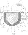
- FIGS. 1 and 2 a preferred embodiment of the new device is designated in its entirety by the reference numeral 10.
- the device 10 includes at least one sensor unit 12, which is designed to deliver a respective current 3D image of the hazardous working area of an automated machine at defined time intervals.
- the sensor unit 12 is a stereo camera system comprising at least a first camera 14 and a second camera 16.
- the cameras 14, 16 provide two slightly offset images of the work area to be protected. Due to the (known) offset of the cameras 14, 16 to each other and with the aid of trigonometric relationships, the distance from the sensor unit 12 to objects in the working area can be determined on the basis of the camera images.
- a preferred sensor unit is mentioned in the opening paragraph EP 1 543 270 B1 described, the disclosure of which is incorporated herein by reference in its entirety.
- the sensor unit 12 may include a runtime camera. This is to be understood as a camera which, on the one hand, supplies 2D images of a region to be monitored. In addition, the camera provides distance information obtained from a runtime measurement. In addition, the sensor unit 12 may be designed as a 3D scanner and / or another technology to create 3D images of a workspace to be secured.
- the device 10 may include a plurality of sensor units 12, as shown in FIG Fig. 2 is illustrated by the sensor units 12a, 12b, 12c, 12d.
- multiple 1D and / or 2D sensors in pairs and / or as a whole may form a 3D sensor unit that provides the required 3D images from the workspace. It is therefore not absolutely necessary, although preferred, to use a stereo camera system as a sensor unit for the new device.
- the apparatus 10 further includes an evaluation unit 18 coupled to a machine controller 20 in the preferred embodiments.
- the machine controller 20 controls an automated machine that operates in Fig. 2 is shown schematically as a robot 22.
- the new device 10 and the new method are particularly suitable for securing the hazardous working area 24 of a robot 22.
- the method and the device are not limited to the protection of robots and can in principle also be used to protect hazardous working areas of other machines, such as for securing automatic transport and conveyor lines, cranes, lifting tools, presses, machining centers and the like.
- the device 10 may also include further sensor units 12 ', such as an RFID reader, with the aid of which a so-called RFID tag 25 can be detected and evaluated.
- RFID tag may, in advantageous embodiments, be used to identify an operator 34 allowed to remain in the hazardous work area 24 of an automated machine, for example, to set up a new operation, perform maintenance or inspection work, and / or in the context another human-machine interaction.
- the device 10 may include a plurality of evaluation units 18, 18 'connected via a bus 26 or other communication medium connected to each other. Moreover, it is possible that part of the signal and data processing power of the sensor unit 12 is accommodated in the evaluation unit 18. For example, the determination of the position of an object on the basis of the stereo images of the cameras 14, 16 done in a computer that also implements the evaluation unit 18 so that the sensor unit 12 according to the present invention does not necessarily have to be housed in a housing that physically from the evaluation unit is disconnected. Rather, the sensor unit in the context of the invention may also be distributed over a plurality of assemblies and / or housing, although it is preferred to realize the sensor unit as compact as possible.
- the reference numeral 28 designates a configuration unit with the aid of which a protective area 30 can be defined in the working area 24 of the robot 22.
- a preferred example of such a configuration unit 28 is in International Patent Application WO 2007/079883 described, the disclosure of which is fully incorporated by reference herein.
- the configuration unit may be a PC on which a user can draw virtual protection areas into a 3D image of the workspace 24 using a configuration tool.
- the configuration tool generates protection space data that is made available to the evaluation unit 18 as a function of the depicted protection areas 3D.
- the evaluation unit 18 "knows" due to the provided protection space data which parts of the work area 24 are defined as a protection area in the sense of the present invention.
- multiple protection areas may be staggered from outside to inside to define, for example, an exterior warning zone and an interior shutdown area about the robot 22.
- virtual protection areas it is possible to define virtual protection areas at different heights and / or at different locations in order, for example, to secure open accesses to the robot 22.
- the virtual protection areas can be combined with mechanical barriers, such as a protective fence or a wall 32.
- the reference numeral 34 denotes a (first) person who approaches the robot 22 and enters the protection area.
- the person 34 is identified using the new device and method as follows Fig. 3 is explained in more detail.
- the new method and apparatus are able to detect the entry of several persons into the protection area 30, as in FIG Fig. 2 is indicated by way of example at the reference numeral 34 '.
- the reference numeral 34 ' when a second person 34 'enters the guard area 30, the same procedure as for the first person 34 enters.
- the speed of the robot 22 is reduced as soon as a first person 34 enters the guard area 30 and the robot 22 continues to work at reduced speed.
- the position of the robot 22 and the person 34 are repeatedly determined at defined time intervals, and it is checked whether the person 34 and the robot 22 come too close.
- the (in Fig. 2 2) around the robot 22 symbolizes here a minimum distance 38, which the person 34 always has to comply with by the robot 22. If the person 34 approaches the robot 22 so far that the minimum distance 38 is undershot, this is detected by means of the evaluation unit 18. In this case, the evaluation unit 18 generates a control signal with the aid of which the machine control 20 immediately stops the working movement of the robot 22.
- the region 36 thus defines a kind of minimal protective cover in which the robot 22 moves and in which a person 34 can not penetrate in the preferred embodiments, without this leading to an immediate emergency stop of the robot 22.
- the robot 22 can operate at a reduced speed, even if the person 34 is in the work area 24 and in particular in the protection area 30.
- the size of the protective sheath 36 is determined depending on the speed and / or direction of movement of the robot 22 (more generally, a machine).
- the evaluation unit receives fail-safe data from the machine control 20, which represent the current movement speed and / or direction.
- the second person 34 If the second person 34 'enters the protection area 30 after the first person 34 has already entered the protection area 30, nothing will change on the working movement of the robot 22 as long as the minimum distance 38 to both persons 34, 34' has been maintained. If both persons have left the protection area 30, this is detected by the evaluation unit 18 with the aid of the sensor unit (s) 12. The evaluation unit 18 generates a corresponding control signal for the machine control 20. In the preferred embodiments, the robot 22 then continues its working movement at high speed, without the need for manual acknowledgment beforehand.
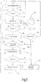
- the new method uses a foreign object detector, which generates a signal 51 in response to a current 3D image, which contains position information on all objects detected in the protection area 30.
- the foreign object detector 50 includes two diverse, redundant 3D scene analysis methods according to FIG EP 1 543 270 B1 , with whose help a fail-safe object detection and position determination is possible. If the foreign object detector 50 does not detect a foreign object 34 in the protection area 30, the method returns to the starting point according to step 52, that is, a new monitoring cycle is started based on a new 3D image.
- a classifier according to step 54 starts in the preferred embodiment.
- the classifier 54 checks whether the detected foreign object 34 is a person.
- the classifier 54 may use databases 56, 58.
- databases 56, 58 personal data are stored in the present exemplary embodiment which characterize selected, defined persons.
- the working movement of the robot 22 is allowed only when one of the selected persons enters the protection area 30. These Although it is a person who is not known or does not belong to the selected persons, the working movement of the robot 22 is stopped. Alternatively or additionally, a warning or alarm signal can be generated.
- the database 58 in this embodiment includes part data characterizing a number of selected parts 59.
- the parts 59 are, for example, workpieces that have to be guided into the protective area 30 for processing.
- step 60 it is checked whether the foreign object 34 is a (known) person. If this is not the case, it is checked according to step 62 whether the detected foreign object is a selected part 59. If this is the case, the detected foreign object is identified as a selected part whose presence in the protection area 30 is permissible. The method accordingly returns to the starting point to begin a new monitoring cycle. However, if the detected foreign object is not a selected part, an emergency stop of the robot 22 is activated according to step 64.
- step 66 a person follower is started who follows the identified person via a series of respectively current 3D images.
- the person follower 66 generates position information 67 representing the current position of the identified person in the protection area 30.
- the classifier 54 and the person follower 66 can be realized, for example, by means of the methods as described in the introduction DE 10 2006 048 166 A1 and or DE 10 2009 031 804 A1 (each with numerous other evidence) are described. Accordingly, the disclosure of these two documents is incorporated herein by reference.
- the classifier 54 and the person follower 66 are therefore implemented as non-failsafe within the meaning of the applicable machine safety standards.
- the classifier 54 and the person follower 66 do not satisfy the requirements of SIL2 and / or PL (d). This means that after a detailed error analysis, it can not be ruled out with sufficient probability that the personal identification and in particular the position determination for the identified person are correct.
- step 68 it is checked whether the first position information of the foreign object detector 50 and the second position information of the personal successor 66 respectively represent the same positions. If so, the non-failsafe determined position of the identified person is verified by the fail-safe determined position of the foreign object detector 50. The position of the person who has determined the person follower 66 can consequently be further processed as fail-safe position information. On the other hand, if the comparison in step 68 indicates that the positions are not identical, the emergency stop of the robot 22 is activated according to step 64.
- the comparison of the position information can be carried out in preferred embodiments based on comparison features that are representative of the particular position. For example, the position of the identified person at the bottom of the protection area 30 can be compared with the corresponding position of the detected foreign object at the bottom of the protection area 30. Alternatively or additionally, the positions of the vertical and horizontal principal axes of the foreign object and the identified person 34 can be compared with each other.
- step 70 body detection is then carried out and the determination of further position information representing the position of individual body parts of the identified person.
- the position of extended arms / hands and / or extended legs is determined by means of the body part detector 70.
- a suitable method is mentioned in the already mentioned DE 10 2009 031 804 A1 and other sources cited therein.
- step 72 it is then checked whether the identified person - if appropriate taking into account the position of their body parts - the minimum distance 38 to the robot 22 complies. If this is not the case, the immediate emergency stop 64 is also activated. Otherwise, the robot 22 remains operational at step 74 and the method returns to the starting point to go through a new monitoring cycle. Operation 74 may be at a reduced rate in the preferred embodiment. Furthermore, depending on the position of the identified person, the trajectory of the robot 22 can be changed. The evaluation unit 18 generates corresponding control signals for the machine control 20.
- the classifier 54, the person follower 66, and the body part detector 70 are shown in the flowchart of FIG Fig. 3 shown as separate steps or blocks. In preferred practical implementations, these steps are software modules which together form a computer program executed in the evaluation unit (s) 18, 18 'of the device 10. Accordingly, the signals, such as the first signal 51, the second signal 65, and the position information 67 of the personal successor 66, in at least some embodiments, are digital data generated in the execution of a computer program.
- the present invention thus describes a novel approach for implementing complex methods, such as, in particular, person identification and tracking, in a safety-related system which serves to safeguard the hazardous working movement of a machine and which accordingly has to meet high requirements, which take the complex procedures themselves can not meet. Failure or failure of complex procedures does not lead to a dangerous situation due to the new approach.
- the failure safety of the new method and the new device is based on already proven principles, in particular on the fail-safe foreign object detection and the fail-safe position determination for detected foreign objects. Due to the new approach, however, the rigid boundaries between man and machine, which previously had to be complied with for safety reasons, can be broken to enable a flexible interaction between man and machine. Movements and speeds of machines, especially robots, can be based on the identification and location of persons changed dynamically and adapted to the respective operating situation. This makes "open" production facilities feasible.
- the classifier and the person follower work in the preferred embodiments according to an active principle, that is, a person must be cyclically recognized and verified by the fail-safe position of the foreign object detector. Otherwise, the machine is brought to a safe state, which is referred to in the context of the present invention as an emergency stop.
- the two objects are treated as a single object. This is permissible under safety aspects, precisely because the two objects can not be distinguished with regard to their position. If the objects separate, either because the two persons separate or because one person turns off the object, the separated objects are recognized as individual objects. Since the foreign object detector 50 monitors the entire protection area 30 in the preferred exemplary embodiments, an emergency stop, if necessary, takes place immediately, as described above Fig. 3 was explained.
- an additional plausibility check advantageously takes place on the basis of the position information of the body part detector. If the plausibility check reveals discrepancies, the emergency stop is likewise activated in the preferred exemplary embodiments. Alternatively, a stepped reaction can take place, for example, first the generation of a warning signal. In addition, the response can also be made dependent on whether the plausibility check in the next cycle leads to matching position information in order to reduce the false alarm rate with sufficiently short cycle times
Claims (14)
- Procédé de sécurisation d'une zone de travail dangereuse (24) d'une machine automatisée (22), comprenant les étapes suivantes :- prévoir au moins une unité de détection (12) qui fournit une image 3D actuelle de la zone de travail (24) à des intervalles de temps définis,- définir au moins une zone de protection (30) dans la zone de travail (24),- surveiller cycliquement la zone de protection (30) à l'aide d'un détecteur d'objets étrangers (50) infaillible, qui génère un premier signal (51) en fonction de l'image 3D actuelle respective et de la zone de protection (30) définie lorsqu'un objet étranger (34) est détecté dans la zone de protection (30), dans lequel le premier signal (51) comprend une première information de position représentative d'une position de l'objet étranger (34) dans la zone de protection (30),- classer cycliquement l'objet étranger (34) dans la zone de protection (30) à l'aide d'un classificateur (54),caractérisé en ce que le classificateur (54) génère un deuxième signal (65) lorsque l'objet étranger (34) est identifié comme étant une personne,
dans lequel la machine (22) est mise en oeuvre en fonction du premier et au moins du deuxième signal (51, 65), et comprenant en outre les étapes suivantes :- suivre la personne identifiée (34) dans une série d'images 3D actuelles à l'aide d'un dispositif de suivi de personne (66),
dans lequel le dispositif de suivi de personne (66) détermine après chaque nouvelle image une deuxième information de position (67) représentant une position actuelle de la personne identifiée (34) dans la zone de protection (30), et- comparer (68) les première et deuxième informations de position pour vérifier si la première information de position du détecteur d'objets étrangers (50) et la deuxième information de position (67) du dispositif de suivi de personne (66) représentent chacune des positions identiques, dans lequel la machine (22) est arrêtée si la position de l'objet étranger (34) selon la première information de position et la position de la personne identifiée selon la deuxième information de position sont différentes l'une de l'autre. - Procédé selon la revendication 1, dans lequel la machine (22) est en outre arrêtée si le classificateur (54) n'identifie pas l'objet étranger (34) comme étant une personne, et dans lequel la machine peut continuer à fonctionner lorsque le classificateur (54) identifie l'objet étranger (34) comme étant une personne.
- Procédé selon la revendication 2, dans lequel le classificateur (54) possède une base de données de personnes (56) contenant des données de personnes caractérisant un nombre de personnes sélectionnées, et dans lequel la machine (22) ne peut en outre continuer à fonctionner que si le classificateur (54) identifie l'objet étranger comme étant l'une des personnes sélectionnées sur la base des données de personnes.
- Procédé selon la revendication 2 ou 3, dans lequel le classificateur (54) comprend un lecteur RFID qui est utilisé pour lire une étiquette RFID.
- Procédé selon l'une des revendications 1 à 4, dans lequel le classificateur (54) possède en outre une base de données de pièces (58) contenant des données de pièces caractérisant un nombre de pièces sélectionnées (59), et dans lequel la machine (22) peut en outre continuer à fonctionner lorsque le classificateur (54) identifie l'objet étranger sur la base des données de pièce comme étant une pièce qui peut pénétrer dans la zone de protection (30).
- Procédé selon l'une des revendications 1 à 5, dans lequel le classificateur (54) comprend un détecteur de parties du corps (70) destiné à déterminer une position de parties du corps de la personne identifiée (34).
- Procédé selon l'une des revendications 1 à 6, dans lequel le classificateur (54) et/ou le dispositif de suivi de personne (66) est/sont de type infaillible.
- Procédé selon l'une des revendications 1 à 7, dans lequel le classificateur (54) est inactif jusqu'à ce que le détecteur d'objets étrangers (50) détecte un objet étranger dans la zone de protection (30).
- Procédé selon l'une des revendications 1 à 7, dans lequel le classificateur (54) est déjà actif avant que le détecteur d'objets étrangers (50) détecte un objet étranger dans la zone de protection (30).
- Procédé selon l'une des revendications 1 à 9, dans lequel une distance minimale (38) par rapport à la machine (22) est définie, et la machine (22) est arrêtée lorsque la personne identifiée (34) s'approche de la machine (22) dans la zone de protection (30) à moins de la distance minimale (38).
- Procédé selon la revendication 10, dans lequel la distance minimale (38) varie en fonction du mouvement actuel de la machine.
- Procédé selon l'une des revendications 1 à 11, dans lequel la machine (22) est mise en oeuvre à vitesse réduite et/ou suivant une trajectoire modifiée lorsque le deuxième signal (65) est présent.
- Dispositif de protection d'une zone de travail dangereuse (24) d'une machine à fonctionnement automatique (22), comprenant au moins une unité de détection (12) qui fournit une image 3D actuelle de la zone de travail (24) à des intervalles de temps définis, une unité de configuration (28) destinée à définir au moins une zone de protection (30) dans la zone de travail (24), et une unité d'évaluation (18) qui comporte un détecteur (50) infaillible, un classificateur (54) et un étage de sortie (19), dans lequel le détecteur d'objets étrangers (50) est conçu pour générer cycliquement un premier signal (51) lorsqu'un objet étranger se trouve dans la zone de protection (30) en fonction de l'image 3D actuelle respective et de la zone de protection (30) définie, dans lequel le premier signal (51) comprend une première information de position représentative d'une position de l'objet étranger dans la zone de protection (30), caractérisé par un dispositif de suivi de personne (66) et par un comparateur (68), dans lequel le classificateur (54) est conçu pour générer cycliquement un deuxième signal (65) lorsque l'objet étranger est identifié comme étant une personne (34), dans lequel le dispositif de suivi de personne (66) est conçu pour suivre la personne (34) identifiée dans une série d'images actuelles respectives et pour déterminer après chaque nouvelle image 3D une deuxième information de position (67) représentant une position actuelle de la personne (34) identifiée dans la zone de protection (30), dans lequel le comparateur (68) est conçu pour comparer les première et deuxième informations de position afin de vérifier si la première information de position du détecteur d'objets étrangers (50) et la deuxième information de position (67) du dispositif de suivi de personne (66) représentent chacune des positions identiques, et pour générer un troisième signal (69) en fonction de celles-ci, et dans lequel l'étage de sortie (19) est conçu pour générer un signal de commande afin d'arrêter la machine (22) en réponse au deuxième signal et en réponse au troisième signal, dans lequel le signal de commande est conçu pour arrêter la machine (22) lorsque la position de l'objet étranger selon la première information de position et la position de la personne identifiée selon la deuxième information de position sont différentes l'une de l'autre.
- Produit de programme d'ordinateur comportant un support de données sur lequel est stocké un code de programme qui est conçu pour mettre en oeuvre un procédé comprenant toutes les étapes du procédé selon l'une des revendications 1 à 12 lorsque le code de programme est exécuté sur une unité d'évaluation d'un dispositif selon la revendication 13.
Applications Claiming Priority (2)
| Application Number | Priority Date | Filing Date | Title |
|---|---|---|---|
| DE102012102236A DE102012102236A1 (de) | 2012-03-16 | 2012-03-16 | Verfahren und Vorrichtung zum Absichern eines gefährlichen Arbeitsbereichs einer automatisiert arbeitenden Maschine |
| PCT/EP2013/054833 WO2013135608A1 (fr) | 2012-03-16 | 2013-03-11 | Procédé et dispositif destinés sécuriser une zone de travail dangereuse d'une machine à fonctionnement automatique. |
Publications (2)
| Publication Number | Publication Date |
|---|---|
| EP2825812A1 EP2825812A1 (fr) | 2015-01-21 |
| EP2825812B1 true EP2825812B1 (fr) | 2018-09-05 |
Family
ID=47878021
Family Applications (1)
| Application Number | Title | Priority Date | Filing Date |
|---|---|---|---|
| EP13709083.3A Active EP2825812B1 (fr) | 2012-03-16 | 2013-03-11 | Procédé et dispositif destinés sécuriser une zone de travail dangereuse d'une machine à fonctionnement automatique. |
Country Status (8)
| Country | Link |
|---|---|
| US (1) | US9489730B2 (fr) |
| EP (1) | EP2825812B1 (fr) |
| JP (1) | JP6333741B2 (fr) |
| CN (1) | CN104169630B (fr) |
| DE (1) | DE102012102236A1 (fr) |
| HK (1) | HK1202916A1 (fr) |
| IN (1) | IN2014MN01837A (fr) |
| WO (1) | WO2013135608A1 (fr) |
Cited By (1)
| Publication number | Priority date | Publication date | Assignee | Title |
|---|---|---|---|---|
| EP4307249A1 (fr) * | 2022-07-13 | 2024-01-17 | Siemens Aktiengesellschaft | Système de surveillance doté d'un détecteur de personnes |
Families Citing this family (74)
| Publication number | Priority date | Publication date | Assignee | Title |
|---|---|---|---|---|
| US9804576B2 (en) * | 2013-02-27 | 2017-10-31 | Rockwell Automation Technologies, Inc. | Recognition-based industrial automation control with position and derivative decision reference |
| US9393695B2 (en) | 2013-02-27 | 2016-07-19 | Rockwell Automation Technologies, Inc. | Recognition-based industrial automation control with person and object discrimination |
| US9798302B2 (en) | 2013-02-27 | 2017-10-24 | Rockwell Automation Technologies, Inc. | Recognition-based industrial automation control with redundant system input support |
| US9498885B2 (en) | 2013-02-27 | 2016-11-22 | Rockwell Automation Technologies, Inc. | Recognition-based industrial automation control with confidence-based decision support |
| US9251598B2 (en) * | 2014-04-10 | 2016-02-02 | GM Global Technology Operations LLC | Vision-based multi-camera factory monitoring with dynamic integrity scoring |
| US9921300B2 (en) | 2014-05-19 | 2018-03-20 | Rockwell Automation Technologies, Inc. | Waveform reconstruction in a time-of-flight sensor |
| US9696424B2 (en) | 2014-05-19 | 2017-07-04 | Rockwell Automation Technologies, Inc. | Optical area monitoring with spot matrix illumination |
| US11243294B2 (en) | 2014-05-19 | 2022-02-08 | Rockwell Automation Technologies, Inc. | Waveform reconstruction in a time-of-flight sensor |
| US9256944B2 (en) * | 2014-05-19 | 2016-02-09 | Rockwell Automation Technologies, Inc. | Integration of optical area monitoring with industrial machine control |
| DE102014210612A1 (de) * | 2014-06-04 | 2015-12-17 | Holzma Plattenaufteiltechnik Gmbh | Verfahren zum Betreiben einerPlattenbearbeitungsanlage, sowiePlattenbearbeitungsanlage |
| US9902061B1 (en) * | 2014-08-25 | 2018-02-27 | X Development Llc | Robot to human feedback |
| DE202014104531U1 (de) * | 2014-09-23 | 2014-10-02 | Leuze Electronic Gmbh + Co. Kg | Sensor zur Erfassung von Objekten in einem Überwachungsbereich |
| US9625108B2 (en) | 2014-10-08 | 2017-04-18 | Rockwell Automation Technologies, Inc. | Auxiliary light source associated with an industrial application |
| US9623560B1 (en) * | 2014-11-26 | 2017-04-18 | Daniel Theobald | Methods of operating a mechanism and systems related therewith |
| US20160182833A1 (en) * | 2014-12-23 | 2016-06-23 | Signazon.Com | Camera System for Cutting Table |
| DE112016000264T5 (de) * | 2015-03-04 | 2017-09-28 | Abb Ag | Sicherheitssteuersystem und Verfahren zum Betrieb eines Sicherheitssteuersystems |
| US9805460B2 (en) * | 2015-03-27 | 2017-10-31 | Rockwell Automation Technologies, Inc. | Systems and methods for assessing a facility based on audio/visual delta analysis |
| JP6177837B2 (ja) * | 2015-06-30 | 2017-08-09 | ファナック株式会社 | 視覚センサを用いたロボットシステム |
| CN106406301B (zh) * | 2015-07-29 | 2020-09-18 | 苏州宝时得电动工具有限公司 | 自动割草设备及其安全自启系统和方法 |
| US10198706B2 (en) * | 2015-07-31 | 2019-02-05 | Locus Robotics Corp. | Operator identification and performance tracking |
| JP6088605B1 (ja) * | 2015-08-31 | 2017-03-01 | ファナック株式会社 | 視覚センサを用いたロボットシステム |
| CN105425308A (zh) * | 2015-12-18 | 2016-03-23 | 同方威视技术股份有限公司 | 物品跟踪系统和方法 |
| US11000078B2 (en) * | 2015-12-28 | 2021-05-11 | Xin Jin | Personal airbag device for preventing bodily injury |
| EP3189947A1 (fr) * | 2016-01-07 | 2017-07-12 | Sick Ag | Procede de configuration et de fonctionnement d'une cellule de travail automatisee surveillee et dispositif de configuration |
| DE102016100445A1 (de) * | 2016-01-12 | 2017-07-13 | Pilz Gmbh & Co. Kg | Sicherheitseinrichtung und Verfahren zum Überwachen einer Maschine |
| JP6733239B2 (ja) * | 2016-03-18 | 2020-07-29 | セイコーエプソン株式会社 | 制御装置及びロボットシステム |
| CN107717982B (zh) * | 2016-08-12 | 2020-09-25 | 财团法人工业技术研究院 | 机械手臂的控制装置及操作方法 |
| US11000953B2 (en) * | 2016-08-17 | 2021-05-11 | Locus Robotics Corp. | Robot gamification for improvement of operator performance |
| JP6822069B2 (ja) * | 2016-11-01 | 2021-01-27 | オムロン株式会社 | 監視システム、監視装置、および監視方法 |
| WO2018091064A1 (fr) * | 2016-11-15 | 2018-05-24 | Abb Schweiz Ag | Système du type robot industriel comprenant une pluralité de robots et une pluralité de capteurs de sécurité |
| ES2673167B2 (es) * | 2016-12-20 | 2018-10-10 | Universidad De Extremadura | Vídeo cortina de seguridad para detección redundante y direccional de acceso a zona de peligro asociada a maquinaria industrial |
| US11518051B2 (en) | 2017-02-07 | 2022-12-06 | Veo Robotics, Inc. | Dynamic, interactive signaling of safety-related conditions in a monitored environment |
| US11541543B2 (en) | 2017-02-07 | 2023-01-03 | Veo Robotics, Inc. | Dynamic, interactive signaling of safety-related conditions in a monitored environment |
| US11820025B2 (en) | 2017-02-07 | 2023-11-21 | Veo Robotics, Inc. | Safe motion planning for machinery operation |
| JP2018126818A (ja) * | 2017-02-07 | 2018-08-16 | トヨタ自動車株式会社 | ロボット制御装置 |
| EP4088891A1 (fr) | 2017-02-07 | 2022-11-16 | Veo Robotics, Inc. | Surveillance de sécurité d'espace de travail et commande d'équipement |
| DE102017202004A1 (de) * | 2017-02-08 | 2018-08-09 | Thyssenkrupp Ag | Vorrichtung zur Absicherung eines maschinell gesteuerten Handhabungsgeräts und Verfahren |
| EP3582642A4 (fr) | 2017-02-20 | 2021-01-13 | 3M Innovative Properties Company | Articles optiques et systèmes interagissant avec ceux-ci |
| DE102017104466B4 (de) * | 2017-03-03 | 2020-09-03 | YUMARR Automation Pty. Ltd. | Vorrichtung, Anordnung und Verfahren zur Sicherung eines Gefahrenbereichs einer Untertage-Maschine |
| JP6866773B2 (ja) * | 2017-06-01 | 2021-04-28 | オムロン株式会社 | 安全制御装置、安全制御装置の制御方法、情報処理プログラム、および記録媒体 |
| KR101785998B1 (ko) * | 2017-06-26 | 2017-10-18 | 주식회사 썬에이치에스티 | 안전사고예방을 위한 출입감지시스템 |
| EP3422053B1 (fr) * | 2017-06-28 | 2021-05-19 | Datalogic IP Tech S.r.l. | Système de sécurité |
| EP3427904B1 (fr) * | 2017-07-13 | 2020-06-10 | Siemens Aktiengesellschaft | Système comprenant un manipulateur et un dispositif de limitation d'un espace de travail |
| JP6687573B2 (ja) | 2017-09-07 | 2020-04-22 | ファナック株式会社 | ロボットシステム |
| WO2019064108A1 (fr) | 2017-09-27 | 2019-04-04 | 3M Innovative Properties Company | Système de gestion d'équipement de protection personnel utilisant des motifs optiques pour un équipement et une surveillance de sécurité |
| DE102017123295A1 (de) * | 2017-10-06 | 2019-04-11 | Pilz Gmbh & Co. Kg | Sicherheitssystem zur Absicherung eines kooperativen Betriebs von Menschen, Robotern und Maschinen |
| DE102017218917A1 (de) * | 2017-10-24 | 2019-04-25 | Robert Bosch Gmbh | Überwachungsvorrichtung, Industrieanlage, Verfahren zur Überwachung sowie Computerprogramm |
| KR102499576B1 (ko) * | 2018-01-08 | 2023-02-15 | 삼성전자주식회사 | 전자 장치 및 그 제어 방법 |
| EP3528077B2 (fr) | 2018-02-16 | 2023-11-01 | Pilz GmbH & Co. KG | Système pour protéger une personne d'une machine fonctionnant de manière autonome |
| DE102018204508A1 (de) * | 2018-03-23 | 2019-09-26 | Kuka Deutschland Gmbh | Verfahren und System zum Betreiben eines Roboters |
| US11763111B2 (en) * | 2018-05-04 | 2023-09-19 | Rowan Companies, Inc. | System and method for locating personnel at muster station on offshore unit |
| EP3572971B1 (fr) * | 2018-05-22 | 2021-02-24 | Sick Ag | Protection d'une zone de surveillance à au moins une machine |
| CN112514548B (zh) * | 2018-08-01 | 2021-10-15 | 株式会社富士 | 元件安装系统 |
| WO2020039544A1 (fr) * | 2018-08-23 | 2020-02-27 | 株式会社Fuji | Dispositif de gestion de travail mobile, dispositif de travail mobile, système de montage, et procédé de gestion de travail mobile |
| US10325485B1 (en) * | 2018-09-11 | 2019-06-18 | Rockwell Automation Technologies, Inc. | System or process to detect, discriminate, aggregate, track, and rank safety related information in a collaborative workspace |
| JP7224843B2 (ja) * | 2018-10-15 | 2023-02-20 | 株式会社今仙電機製作所 | ロボット、このロボットを備えた搬送車、このロボットの制御方法及び制御プログラム |
| EP3709106B1 (fr) | 2019-03-11 | 2021-01-06 | Sick Ag | Mise en sécurité d'une machine |
| DE102019114854B4 (de) * | 2019-06-03 | 2021-06-24 | Pilz Gmbh & Co. Kg | Vorrichtung und Verfahren zur energieeffizienten Ausführung einer Sicherheitsfunktion |
| US11320830B2 (en) | 2019-10-28 | 2022-05-03 | Deere & Company | Probabilistic decision support for obstacle detection and classification in a working area |
| IT201900021108A1 (it) * | 2019-11-13 | 2021-05-13 | Gamma System S R L | Sistema di sicurezza per un macchinario industriale |
| DE102020101482B3 (de) * | 2020-01-22 | 2021-04-15 | Sick Ag | Sicherheitssystem und Verfahren |
| EP3859382B1 (fr) * | 2020-01-28 | 2022-08-03 | Sick Ag | Système de sécurité et procédé de localisation d'une personne ou d'un objet dans une zone de surveillance à l'aide d'un système de sécurité |
| EP3869240A1 (fr) * | 2020-02-18 | 2021-08-25 | Leuze electronic GmbH + Co. KG | Agencement de capteurs et procédé de fonctionnement d'un agencement de capteurs |
| CN111597903B (zh) * | 2020-04-17 | 2023-04-28 | 江门明浩电力工程监理有限公司 | 一种配网智能监控箱及其监控方法 |
| DE102020112699A1 (de) * | 2020-05-11 | 2021-11-11 | Sick Ag | Sicherheitssystem |
| WO2022054345A1 (fr) | 2020-09-14 | 2022-03-17 | コニカミノルタ株式会社 | Dispositif de surveillance de sécurité, procédé de surveillance de sécurité et programme |
| AT17459U1 (de) * | 2021-01-21 | 2022-05-15 | Altendorf Gmbh | Sicherheitseinrichtung für Werkzeugmaschinen |
| EP4068038B1 (fr) * | 2021-03-31 | 2024-05-01 | Mobile Industrial Robots A/S | Renvoi de zones de sécurité à un autre équipement |
| EP4070920A1 (fr) * | 2021-04-08 | 2022-10-12 | Siemens Aktiengesellschaft | Système de robot mobile autonome et procédé de fonctionnement |
| CN113364359A (zh) * | 2021-05-13 | 2021-09-07 | 联合汽车电子有限公司 | 无位置传感器控制方法、装置及存储介质 |
| DE202022103201U1 (de) | 2022-06-07 | 2023-10-17 | Leuze Electronic Gmbh + Co. Kg | Überwachungseinrichtung |
| EP4170438A1 (fr) * | 2022-06-07 | 2023-04-26 | Pimu Llc | Système de commande de sécurité |
| DE202022103234U1 (de) * | 2022-06-08 | 2023-09-20 | Leuze Electronic Gmbh + Co. Kg | Überwachungseinrichtung |
| DE102022116305A1 (de) | 2022-06-30 | 2024-01-04 | Sick Ag | Sicherheitssystem und Verfahren mit einem Sicherheitssystem |
Citations (9)
| Publication number | Priority date | Publication date | Assignee | Title |
|---|---|---|---|---|
| WO2004029502A1 (fr) | 2002-09-24 | 2004-04-08 | Pilz Gmbh & Co. Kg | Procede et dispositif pour securiser une zone de risque |
| EP1418380A1 (fr) | 2002-11-06 | 2004-05-12 | Leuze lumiflex GmbH + Co. KG | Procédé et dispositif pour surveiller une zone |
| EP1586805A1 (fr) | 2004-04-14 | 2005-10-19 | Sick Ag | Procédé pour surveiller une zone de surveillance |
| DE102004043514A1 (de) | 2004-09-08 | 2006-03-09 | Sick Ag | Verfahren und Vorrichtung zum Steuern einer sicherheitsrelevanten Funktion einer Maschine |
| DE102006008805A1 (de) | 2006-02-25 | 2007-09-06 | Leuze Lumiflex Gmbh + Co. Kg | Optischer Sensor und Verfahren zur Überwachung einer Schutzzone mittels eines optischen Sensors |
| DE102006048166A1 (de) | 2006-08-02 | 2008-02-07 | Daimler Ag | Verfahren zur Beobachtung einer Person in einem industriellen Umfeld |
| DE102009031804A1 (de) | 2009-07-06 | 2010-03-11 | Daimler Ag | Verfahren zur Objekterkennung und Objektverfolgung |
| EP2282106A1 (fr) | 2009-08-07 | 2011-02-09 | Sick Ag | Sécurité d'une zone accessible uniquement par une seule porte d'accès |
| US20110050878A1 (en) | 2009-08-28 | 2011-03-03 | Gm Global Technology Operations, Inc. | Vision System for Monitoring Humans in Dynamic Environments |
Family Cites Families (17)
| Publication number | Priority date | Publication date | Assignee | Title |
|---|---|---|---|---|
| DE10152543A1 (de) | 2001-10-24 | 2003-05-08 | Sick Ag | Verfahren und Vorrichtung zum Steuern einer sicherheitsrelevanten Funktion einer Maschine |
| JP4006577B2 (ja) * | 2002-03-13 | 2007-11-14 | オムロン株式会社 | 監視装置 |
| JP2004069497A (ja) * | 2002-08-06 | 2004-03-04 | Sumitomo Osaka Cement Co Ltd | 監視装置および監視方法 |
| US7729511B2 (en) * | 2002-09-24 | 2010-06-01 | Pilz Gmbh & Co. Kg | Method and device for safeguarding a hazardous area |
| DE102004043515A1 (de) | 2004-09-08 | 2006-03-09 | Sick Ag | Verfahren und Vorrichtung zum Erfassen eines Objekts |
| DE202004020863U1 (de) | 2004-09-17 | 2006-04-06 | Sick Ag | Vorrichtung zur Sicherung eines gefährdeten Arbeitsbereichs |
| DE102005003827B4 (de) | 2005-01-26 | 2007-01-04 | Fraunhofer-Gesellschaft zur Förderung der angewandten Forschung e.V. | Vorrichtung und Verfahren zur Interaktion zwischen einem Menschen und einer Robotereinheit an einem Roboterarbeitsplatz |
| US7888825B2 (en) * | 2005-07-19 | 2011-02-15 | Omron Corporation | Worker safety management system |
| DE102005056265A1 (de) * | 2005-11-14 | 2007-05-16 | Pilz Gmbh & Co Kg | Vorrichtung und Verfahren zum Überwachen eines Raumbereichs, insbesondere zum Absichern eines Gefahrenbereichs einer automatisiert arbeitenden Anlage |
| DE102005063217C5 (de) | 2005-12-22 | 2022-08-18 | Pilz Gmbh & Co. Kg | Verfahren zum Konfigurieren einer Überwachungseinrichtung zum Überwachen eines Raumbereichsund entsprechende Überwachungseinrichtung |
| JP4830696B2 (ja) * | 2006-07-31 | 2011-12-07 | オムロン株式会社 | 物体認識装置、監視システム、物体認識方法、物体認識プログラム、および該プログラムを記録した記録媒体 |
| DE102006048163B4 (de) | 2006-07-31 | 2013-06-06 | Pilz Gmbh & Co. Kg | Kamerabasierte Überwachung bewegter Maschinen und/oder beweglicher Maschinenelemente zur Kollisionsverhinderung |
| DE102007007576B4 (de) | 2007-02-15 | 2009-01-15 | Kuka Roboter Gmbh | Verfahren und Vorrichtung zum Sichern eines Arbeitsraums |
| JP5343641B2 (ja) * | 2009-03-12 | 2013-11-13 | 株式会社Ihi | ロボット装置の制御装置及びロボット装置の制御方法 |
| ES2384750T3 (es) * | 2009-10-01 | 2012-07-11 | Kapsch Trafficcom Ag | Dispositivos y procedimientos para la clasificación de vehículos |
| US9143843B2 (en) * | 2010-12-09 | 2015-09-22 | Sealed Air Corporation | Automated monitoring and control of safety in a production area |
| DE102010017857B4 (de) * | 2010-04-22 | 2019-08-08 | Sick Ag | 3D-Sicherheitsvorrichtung und Verfahren zur Absicherung und Bedienung mindestens einer Maschine |
-
2012
- 2012-03-16 DE DE102012102236A patent/DE102012102236A1/de not_active Withdrawn
-
2013
- 2013-03-11 WO PCT/EP2013/054833 patent/WO2013135608A1/fr active Application Filing
- 2013-03-11 IN IN1837MUN2014 patent/IN2014MN01837A/en unknown
- 2013-03-11 CN CN201380014093.7A patent/CN104169630B/zh active Active
- 2013-03-11 EP EP13709083.3A patent/EP2825812B1/fr active Active
- 2013-03-11 JP JP2014561389A patent/JP6333741B2/ja active Active
-
2014
- 2014-08-26 US US14/468,445 patent/US9489730B2/en active Active
-
2015
- 2015-04-01 HK HK15103319.1A patent/HK1202916A1/xx not_active IP Right Cessation
Patent Citations (9)
| Publication number | Priority date | Publication date | Assignee | Title |
|---|---|---|---|---|
| WO2004029502A1 (fr) | 2002-09-24 | 2004-04-08 | Pilz Gmbh & Co. Kg | Procede et dispositif pour securiser une zone de risque |
| EP1418380A1 (fr) | 2002-11-06 | 2004-05-12 | Leuze lumiflex GmbH + Co. KG | Procédé et dispositif pour surveiller une zone |
| EP1586805A1 (fr) | 2004-04-14 | 2005-10-19 | Sick Ag | Procédé pour surveiller une zone de surveillance |
| DE102004043514A1 (de) | 2004-09-08 | 2006-03-09 | Sick Ag | Verfahren und Vorrichtung zum Steuern einer sicherheitsrelevanten Funktion einer Maschine |
| DE102006008805A1 (de) | 2006-02-25 | 2007-09-06 | Leuze Lumiflex Gmbh + Co. Kg | Optischer Sensor und Verfahren zur Überwachung einer Schutzzone mittels eines optischen Sensors |
| DE102006048166A1 (de) | 2006-08-02 | 2008-02-07 | Daimler Ag | Verfahren zur Beobachtung einer Person in einem industriellen Umfeld |
| DE102009031804A1 (de) | 2009-07-06 | 2010-03-11 | Daimler Ag | Verfahren zur Objekterkennung und Objektverfolgung |
| EP2282106A1 (fr) | 2009-08-07 | 2011-02-09 | Sick Ag | Sécurité d'une zone accessible uniquement par une seule porte d'accès |
| US20110050878A1 (en) | 2009-08-28 | 2011-03-03 | Gm Global Technology Operations, Inc. | Vision System for Monitoring Humans in Dynamic Environments |
Non-Patent Citations (3)
| Title |
|---|
| D. SCHULZ ET AL.: "People Tracking with Anonymous and ID-Sensors Using Rao-Blackwellised Particle Filters", IJCAI, 2003, pages 1 - 6, XP055590426 |
| JÜRGEN GRAF: "Sichere Mensch-Roboter-Kooperation durch Auswertung von Bilfolgen", DISSERTATION, pages 1 - 204 |
| R. CUCCHIARA ET AL.: "Mutual Calibration of Camera Motes and RFIDs for People Localization and Identification", UNIVERSITY OF MODENA AND REGGIO EMILIA, pages 1 - 8, XP055590424 |
Cited By (2)
| Publication number | Priority date | Publication date | Assignee | Title |
|---|---|---|---|---|
| EP4307249A1 (fr) * | 2022-07-13 | 2024-01-17 | Siemens Aktiengesellschaft | Système de surveillance doté d'un détecteur de personnes |
| WO2024012746A1 (fr) | 2022-07-13 | 2024-01-18 | Siemens Aktiengesellschaft | Système de surveillance comprenant un détecteur de personne |
Also Published As
| Publication number | Publication date |
|---|---|
| CN104169630A (zh) | 2014-11-26 |
| JP6333741B2 (ja) | 2018-05-30 |
| WO2013135608A1 (fr) | 2013-09-19 |
| JP2015515613A (ja) | 2015-05-28 |
| CN104169630B (zh) | 2017-04-19 |
| US20150049911A1 (en) | 2015-02-19 |
| HK1202916A1 (en) | 2015-10-09 |
| EP2825812A1 (fr) | 2015-01-21 |
| IN2014MN01837A (fr) | 2015-07-03 |
| US9489730B2 (en) | 2016-11-08 |
| DE102012102236A1 (de) | 2013-09-19 |
Similar Documents
| Publication | Publication Date | Title |
|---|---|---|
| EP2825812B1 (fr) | Procédé et dispositif destinés sécuriser une zone de travail dangereuse d'une machine à fonctionnement automatique. | |
| DE102018121388B4 (de) | Robotersystem | |
| EP2989369B1 (fr) | Dispositif et procédé de sécurisation d'une machine travaillant de manière automatisée | |
| EP3701340B1 (fr) | Dispositif de surveillance, équipement industriel, procédé de surveillance et programme informatique | |
| EP3011225B1 (fr) | Dispositif et procédé pour protéger une machine fonctionnant de manière automatisée | |
| EP2838698B2 (fr) | Agencement d'un robot et procédé de commande d'un robot | |
| EP3611422B1 (fr) | Dispositif capteur et procédé de sécurisation d'une zone de surveillance | |
| EP3200122B1 (fr) | Capteur optoelectronique et procede de reconnaissance fiable d'objets de taille minimum | |
| WO2008014909A1 (fr) | Surveillance à base de caméra de machines comportant des éléments de machine mobiles en vue d'éviter les collisions | |
| DE102007007576A1 (de) | Verfahren und Vorrichtung zum Sichern eines Arbeitsraums | |
| DE102018118265B4 (de) | Verfahren und Überwachungssystem zum Absichern einer Maschine | |
| DE112017002639T5 (de) | Robotersteuerungsvorrichtung | |
| EP1366867A2 (fr) | Méthode et dispositif pour éviter les collisions entre des robots industriels et d'autres objects | |
| EP1367314A2 (fr) | Dispositif de surveillance du champ d'action d'un organe de travail | |
| EP3744482B1 (fr) | Fixation d'une pièce de machine mobile | |
| DE102012007242A1 (de) | Vorrichtung und Verfahren zur sicheren Mensch-Roboter-Kooperation | |
| WO2018041743A1 (fr) | Procédé et dispositif de coopération homme-machine | |
| EP2946256B1 (fr) | Installation, en particulier usine | |
| EP3754244B1 (fr) | Dispositif et procédé de surveillance d'une zone dangereuse | |
| DE102016222245A1 (de) | Einrichtung und Verfahren zur Einwirkung auf Gegenstände | |
| EP3150898B1 (fr) | Procede de commande automatisee d'un composant de machine | |
| DE102019127826B4 (de) | Sicherer optoelektronischer Sensor und Verfahren zum Absichern eines Überwachungsbereichs | |
| EP3470879B1 (fr) | Capteur optoélectronique et procédé de détection sécurisée d'objets | |
| DE102017119275A1 (de) | Lichtvorhang | |
| EP3867560B1 (fr) | Procédé servant à adapter une fonction de protection pendant un fonctionnement d'une machine en générant une zone de fenêtre non surveillée avec des systèmes de protection sans séparation, et dispositif de protection |
Legal Events
| Date | Code | Title | Description |
|---|---|---|---|
| PUAI | Public reference made under article 153(3) epc to a published international application that has entered the european phase |
Free format text: ORIGINAL CODE: 0009012 |
|
| 17P | Request for examination filed |
Effective date: 20140820 |
|
| AK | Designated contracting states |
Kind code of ref document: A1 Designated state(s): AL AT BE BG CH CY CZ DE DK EE ES FI FR GB GR HR HU IE IS IT LI LT LU LV MC MK MT NL NO PL PT RO RS SE SI SK SM TR |
|
| AX | Request for extension of the european patent |
Extension state: BA ME |
|
| DAX | Request for extension of the european patent (deleted) | ||
| REG | Reference to a national code |
Ref country code: HK Ref legal event code: DE Ref document number: 1202916 Country of ref document: HK |
|
| GRAP | Despatch of communication of intention to grant a patent |
Free format text: ORIGINAL CODE: EPIDOSNIGR1 |
|
| STAA | Information on the status of an ep patent application or granted ep patent |
Free format text: STATUS: GRANT OF PATENT IS INTENDED |
|
| INTG | Intention to grant announced |
Effective date: 20180416 |
|
| GRAS | Grant fee paid |
Free format text: ORIGINAL CODE: EPIDOSNIGR3 |
|
| GRAA | (expected) grant |
Free format text: ORIGINAL CODE: 0009210 |
|
| STAA | Information on the status of an ep patent application or granted ep patent |
Free format text: STATUS: THE PATENT HAS BEEN GRANTED |
|
| AK | Designated contracting states |
Kind code of ref document: B1 Designated state(s): AL AT BE BG CH CY CZ DE DK EE ES FI FR GB GR HR HU IE IS IT LI LT LU LV MC MK MT NL NO PL PT RO RS SE SI SK SM TR |
|
| REG | Reference to a national code |
Ref country code: GB Ref legal event code: FG4D Free format text: NOT ENGLISH |
|
| REG | Reference to a national code |
Ref country code: CH Ref legal event code: EP |
|
| REG | Reference to a national code |
Ref country code: AT Ref legal event code: REF Ref document number: 1038227 Country of ref document: AT Kind code of ref document: T Effective date: 20180915 |
|
| REG | Reference to a national code |
Ref country code: CH Ref legal event code: NV Representative=s name: RENTSCH PARTNER AG, CH |
|
| REG | Reference to a national code |
Ref country code: IE Ref legal event code: FG4D Free format text: LANGUAGE OF EP DOCUMENT: GERMAN |
|
| REG | Reference to a national code |
Ref country code: DE Ref legal event code: R096 Ref document number: 502013011013 Country of ref document: DE |
|
| REG | Reference to a national code |
Ref country code: NL Ref legal event code: MP Effective date: 20180905 |
|
| REG | Reference to a national code |
Ref country code: LT Ref legal event code: MG4D |
|
| PG25 | Lapsed in a contracting state [announced via postgrant information from national office to epo] |
Ref country code: LT Free format text: LAPSE BECAUSE OF FAILURE TO SUBMIT A TRANSLATION OF THE DESCRIPTION OR TO PAY THE FEE WITHIN THE PRESCRIBED TIME-LIMIT Effective date: 20180905 Ref country code: RS Free format text: LAPSE BECAUSE OF FAILURE TO SUBMIT A TRANSLATION OF THE DESCRIPTION OR TO PAY THE FEE WITHIN THE PRESCRIBED TIME-LIMIT Effective date: 20180905 Ref country code: GR Free format text: LAPSE BECAUSE OF FAILURE TO SUBMIT A TRANSLATION OF THE DESCRIPTION OR TO PAY THE FEE WITHIN THE PRESCRIBED TIME-LIMIT Effective date: 20181206 Ref country code: FI Free format text: LAPSE BECAUSE OF FAILURE TO SUBMIT A TRANSLATION OF THE DESCRIPTION OR TO PAY THE FEE WITHIN THE PRESCRIBED TIME-LIMIT Effective date: 20180905 Ref country code: SE Free format text: LAPSE BECAUSE OF FAILURE TO SUBMIT A TRANSLATION OF THE DESCRIPTION OR TO PAY THE FEE WITHIN THE PRESCRIBED TIME-LIMIT Effective date: 20180905 Ref country code: NO Free format text: LAPSE BECAUSE OF FAILURE TO SUBMIT A TRANSLATION OF THE DESCRIPTION OR TO PAY THE FEE WITHIN THE PRESCRIBED TIME-LIMIT Effective date: 20181205 Ref country code: BG Free format text: LAPSE BECAUSE OF FAILURE TO SUBMIT A TRANSLATION OF THE DESCRIPTION OR TO PAY THE FEE WITHIN THE PRESCRIBED TIME-LIMIT Effective date: 20181205 |
|
| PG25 | Lapsed in a contracting state [announced via postgrant information from national office to epo] |
Ref country code: HR Free format text: LAPSE BECAUSE OF FAILURE TO SUBMIT A TRANSLATION OF THE DESCRIPTION OR TO PAY THE FEE WITHIN THE PRESCRIBED TIME-LIMIT Effective date: 20180905 Ref country code: LV Free format text: LAPSE BECAUSE OF FAILURE TO SUBMIT A TRANSLATION OF THE DESCRIPTION OR TO PAY THE FEE WITHIN THE PRESCRIBED TIME-LIMIT Effective date: 20180905 Ref country code: AL Free format text: LAPSE BECAUSE OF FAILURE TO SUBMIT A TRANSLATION OF THE DESCRIPTION OR TO PAY THE FEE WITHIN THE PRESCRIBED TIME-LIMIT Effective date: 20180905 |
|
| PG25 | Lapsed in a contracting state [announced via postgrant information from national office to epo] |
Ref country code: CZ Free format text: LAPSE BECAUSE OF FAILURE TO SUBMIT A TRANSLATION OF THE DESCRIPTION OR TO PAY THE FEE WITHIN THE PRESCRIBED TIME-LIMIT Effective date: 20180905 Ref country code: ES Free format text: LAPSE BECAUSE OF FAILURE TO SUBMIT A TRANSLATION OF THE DESCRIPTION OR TO PAY THE FEE WITHIN THE PRESCRIBED TIME-LIMIT Effective date: 20180905 Ref country code: RO Free format text: LAPSE BECAUSE OF FAILURE TO SUBMIT A TRANSLATION OF THE DESCRIPTION OR TO PAY THE FEE WITHIN THE PRESCRIBED TIME-LIMIT Effective date: 20180905 Ref country code: NL Free format text: LAPSE BECAUSE OF FAILURE TO SUBMIT A TRANSLATION OF THE DESCRIPTION OR TO PAY THE FEE WITHIN THE PRESCRIBED TIME-LIMIT Effective date: 20180905 Ref country code: IS Free format text: LAPSE BECAUSE OF FAILURE TO SUBMIT A TRANSLATION OF THE DESCRIPTION OR TO PAY THE FEE WITHIN THE PRESCRIBED TIME-LIMIT Effective date: 20190105 Ref country code: EE Free format text: LAPSE BECAUSE OF FAILURE TO SUBMIT A TRANSLATION OF THE DESCRIPTION OR TO PAY THE FEE WITHIN THE PRESCRIBED TIME-LIMIT Effective date: 20180905 Ref country code: PL Free format text: LAPSE BECAUSE OF FAILURE TO SUBMIT A TRANSLATION OF THE DESCRIPTION OR TO PAY THE FEE WITHIN THE PRESCRIBED TIME-LIMIT Effective date: 20180905 |
|
| REG | Reference to a national code |
Ref country code: DE Ref legal event code: R026 Ref document number: 502013011013 Country of ref document: DE |
|
| PLBI | Opposition filed |
Free format text: ORIGINAL CODE: 0009260 |
|
| PG25 | Lapsed in a contracting state [announced via postgrant information from national office to epo] |
Ref country code: SK Free format text: LAPSE BECAUSE OF FAILURE TO SUBMIT A TRANSLATION OF THE DESCRIPTION OR TO PAY THE FEE WITHIN THE PRESCRIBED TIME-LIMIT Effective date: 20180905 Ref country code: PT Free format text: LAPSE BECAUSE OF FAILURE TO SUBMIT A TRANSLATION OF THE DESCRIPTION OR TO PAY THE FEE WITHIN THE PRESCRIBED TIME-LIMIT Effective date: 20190105 Ref country code: SM Free format text: LAPSE BECAUSE OF FAILURE TO SUBMIT A TRANSLATION OF THE DESCRIPTION OR TO PAY THE FEE WITHIN THE PRESCRIBED TIME-LIMIT Effective date: 20180905 |
|
| 26 | Opposition filed |
Opponent name: SICK AG Effective date: 20190507 |
|
| PLAX | Notice of opposition and request to file observation + time limit sent |
Free format text: ORIGINAL CODE: EPIDOSNOBS2 |
|
| PG25 | Lapsed in a contracting state [announced via postgrant information from national office to epo] |
Ref country code: DK Free format text: LAPSE BECAUSE OF FAILURE TO SUBMIT A TRANSLATION OF THE DESCRIPTION OR TO PAY THE FEE WITHIN THE PRESCRIBED TIME-LIMIT Effective date: 20180905 |
|
| PG25 | Lapsed in a contracting state [announced via postgrant information from national office to epo] |
Ref country code: SI Free format text: LAPSE BECAUSE OF FAILURE TO SUBMIT A TRANSLATION OF THE DESCRIPTION OR TO PAY THE FEE WITHIN THE PRESCRIBED TIME-LIMIT Effective date: 20180905 |
|
| PG25 | Lapsed in a contracting state [announced via postgrant information from national office to epo] |
Ref country code: MC Free format text: LAPSE BECAUSE OF FAILURE TO SUBMIT A TRANSLATION OF THE DESCRIPTION OR TO PAY THE FEE WITHIN THE PRESCRIBED TIME-LIMIT Effective date: 20180905 |
|
| PLBB | Reply of patent proprietor to notice(s) of opposition received |
Free format text: ORIGINAL CODE: EPIDOSNOBS3 |
|
| GBPC | Gb: european patent ceased through non-payment of renewal fee |
Effective date: 20190311 |
|
| PG25 | Lapsed in a contracting state [announced via postgrant information from national office to epo] |
Ref country code: LU Free format text: LAPSE BECAUSE OF NON-PAYMENT OF DUE FEES Effective date: 20190311 |
|
| REG | Reference to a national code |
Ref country code: BE Ref legal event code: MM Effective date: 20190331 |
|
| PG25 | Lapsed in a contracting state [announced via postgrant information from national office to epo] |
Ref country code: IE Free format text: LAPSE BECAUSE OF NON-PAYMENT OF DUE FEES Effective date: 20190311 Ref country code: GB Free format text: LAPSE BECAUSE OF NON-PAYMENT OF DUE FEES Effective date: 20190311 |
|
| PG25 | Lapsed in a contracting state [announced via postgrant information from national office to epo] |
Ref country code: BE Free format text: LAPSE BECAUSE OF NON-PAYMENT OF DUE FEES Effective date: 20190331 |
|
| PG25 | Lapsed in a contracting state [announced via postgrant information from national office to epo] |
Ref country code: TR Free format text: LAPSE BECAUSE OF FAILURE TO SUBMIT A TRANSLATION OF THE DESCRIPTION OR TO PAY THE FEE WITHIN THE PRESCRIBED TIME-LIMIT Effective date: 20180905 |
|
| PG25 | Lapsed in a contracting state [announced via postgrant information from national office to epo] |
Ref country code: MT Free format text: LAPSE BECAUSE OF FAILURE TO SUBMIT A TRANSLATION OF THE DESCRIPTION OR TO PAY THE FEE WITHIN THE PRESCRIBED TIME-LIMIT Effective date: 20180905 |
|
| REG | Reference to a national code |
Ref country code: DE Ref legal event code: R100 Ref document number: 502013011013 Country of ref document: DE |
|
| PLCK | Communication despatched that opposition was rejected |
Free format text: ORIGINAL CODE: EPIDOSNREJ1 |
|
| PLBN | Opposition rejected |
Free format text: ORIGINAL CODE: 0009273 |
|
| STAA | Information on the status of an ep patent application or granted ep patent |
Free format text: STATUS: OPPOSITION REJECTED |
|
| PG25 | Lapsed in a contracting state [announced via postgrant information from national office to epo] |
Ref country code: CY Free format text: LAPSE BECAUSE OF FAILURE TO SUBMIT A TRANSLATION OF THE DESCRIPTION OR TO PAY THE FEE WITHIN THE PRESCRIBED TIME-LIMIT Effective date: 20180905 |
|
| 27O | Opposition rejected |
Effective date: 20201110 |
|
| PG25 | Lapsed in a contracting state [announced via postgrant information from national office to epo] |
Ref country code: HU Free format text: LAPSE BECAUSE OF FAILURE TO SUBMIT A TRANSLATION OF THE DESCRIPTION OR TO PAY THE FEE WITHIN THE PRESCRIBED TIME-LIMIT; INVALID AB INITIO Effective date: 20130311 |
|
| PG25 | Lapsed in a contracting state [announced via postgrant information from national office to epo] |
Ref country code: MK Free format text: LAPSE BECAUSE OF FAILURE TO SUBMIT A TRANSLATION OF THE DESCRIPTION OR TO PAY THE FEE WITHIN THE PRESCRIBED TIME-LIMIT Effective date: 20180905 |
|
| PGFP | Annual fee paid to national office [announced via postgrant information from national office to epo] |
Ref country code: FR Payment date: 20230324 Year of fee payment: 11 Ref country code: AT Payment date: 20230322 Year of fee payment: 11 |
|
| PGFP | Annual fee paid to national office [announced via postgrant information from national office to epo] |
Ref country code: IT Payment date: 20230328 Year of fee payment: 11 Ref country code: DE Payment date: 20230425 Year of fee payment: 11 Ref country code: CH Payment date: 20230401 Year of fee payment: 11 |
|
| PGFP | Annual fee paid to national office [announced via postgrant information from national office to epo] |
Ref country code: AT Payment date: 20240321 Year of fee payment: 12 |