EP2824521A2 - Uhrmechanismus, Uhrwerk und Uhr - Google Patents
Uhrmechanismus, Uhrwerk und Uhr Download PDFInfo
- Publication number
- EP2824521A2 EP2824521A2 EP14176314.4A EP14176314A EP2824521A2 EP 2824521 A2 EP2824521 A2 EP 2824521A2 EP 14176314 A EP14176314 A EP 14176314A EP 2824521 A2 EP2824521 A2 EP 2824521A2
- Authority
- EP
- European Patent Office
- Prior art keywords
- lever
- isolation device
- cam
- probe
- blocker
- Prior art date
- Legal status (The legal status is an assumption and is not a legal conclusion. Google has not performed a legal analysis and makes no representation as to the accuracy of the status listed.)
- Pending
Links
Images


Classifications
-
- G—PHYSICS
- G04—HOROLOGY
- G04B—MECHANICALLY-DRIVEN CLOCKS OR WATCHES; MECHANICAL PARTS OF CLOCKS OR WATCHES IN GENERAL; TIME PIECES USING THE POSITION OF THE SUN, MOON OR STARS
- G04B19/00—Indicating the time by visual means
- G04B19/02—Back-gearing arrangements between gear train and hands
-
- G—PHYSICS
- G04—HOROLOGY
- G04B—MECHANICALLY-DRIVEN CLOCKS OR WATCHES; MECHANICAL PARTS OF CLOCKS OR WATCHES IN GENERAL; TIME PIECES USING THE POSITION OF THE SUN, MOON OR STARS
- G04B19/00—Indicating the time by visual means
- G04B19/02—Back-gearing arrangements between gear train and hands
- G04B19/025—Back-gearing arrangements between gear train and hands for simultaneous indicating on several dials
-
- G—PHYSICS
- G04—HOROLOGY
- G04B—MECHANICALLY-DRIVEN CLOCKS OR WATCHES; MECHANICAL PARTS OF CLOCKS OR WATCHES IN GENERAL; TIME PIECES USING THE POSITION OF THE SUN, MOON OR STARS
- G04B19/00—Indicating the time by visual means
- G04B19/06—Dials
- G04B19/08—Geometrical arrangement of the graduations
- G04B19/082—Geometrical arrangement of the graduations varying from the normal closed scale
-
- G—PHYSICS
- G04—HOROLOGY
- G04B—MECHANICALLY-DRIVEN CLOCKS OR WATCHES; MECHANICAL PARTS OF CLOCKS OR WATCHES IN GENERAL; TIME PIECES USING THE POSITION OF THE SUN, MOON OR STARS
- G04B19/00—Indicating the time by visual means
- G04B19/06—Dials
- G04B19/08—Geometrical arrangement of the graduations
- G04B19/087—Geometrical arrangement of the graduations with several separate scales
-
- G—PHYSICS
- G04—HOROLOGY
- G04F—TIME-INTERVAL MEASURING
- G04F7/00—Apparatus for measuring unknown time intervals by non-electric means
- G04F7/04—Apparatus for measuring unknown time intervals by non-electric means using a mechanical oscillator
- G04F7/08—Watches or clocks with stop devices, e.g. chronograph
- G04F7/0866—Special arrangements
- G04F7/0871—Special arrangements with multiple chronograph functions, i.e. to count multiple running times
-
- G—PHYSICS
- G04—HOROLOGY
- G04F—TIME-INTERVAL MEASURING
- G04F7/00—Apparatus for measuring unknown time intervals by non-electric means
- G04F7/04—Apparatus for measuring unknown time intervals by non-electric means using a mechanical oscillator
- G04F7/08—Watches or clocks with stop devices, e.g. chronograph
- G04F7/0866—Special arrangements
- G04F7/0876—Split-time function, e.g. rattrappante
Definitions
- the invention relates to a clock mechanism for indicating and storing a temporal information and a mechanism for correcting a display device for temporal information.
- the invention also relates to a watch movement comprising such a mechanism.
- the invention also relates to a timepiece, in particular a watch, comprising such a movement or such a mechanism.
- the document EP1475681 discloses a device that allows the display of the fractions of a second of a chronograph only when the chronograph is stopped.
- This system uses a cam integral with a pinion rotating at the rate of one revolution per second.
- the time information is displayed by means of a rake which is engaged with the display member, and which is likely to be in contact with the cam.
- the probe of the rake is in contact with the side of the cam and is thus positioned to display the time information.
- the probe of the rake is raised in a predetermined position by an arm or a column wheel so that it is disengaged from the stroke of the cam.
- the document CH700902 relates to a switching mechanism capable of indicating time information on demand.
- This system has the particularity of displaying a day / night information only in setting mode of the timepiece.
- This implements the characteristic elements of the conventional retrograde display device.
- the end of the rod slaves the angular position of the probe so that its tip is not in contact with the sidewall a cam performing a complete revolution in 24h.
- the rod releases the probe which is pressed against the cam under the effect of a return spring.
- the document EP2159652 is a mechanism for displaying the time to display or not the current time. Under the operation of a control lever, the set of hands indicates the time conventionally or it is arranged in a predetermined position.
- This device uses snap cams which are respectively engaged with the kinematic chain of hours and minutes. The hourly information is displayed through rakes respectively engaged with the hour hand and the minute hand. In the non-time display position, the rakes, under the operation of the control lever, are positioned so that their feelers are out of the running cams. As a result, the needle set is disposed in a predetermined position.
- Requirement EP1918792A1 relates to a disengagement device adjoining the conventional retrograde display device which, in the adjustment phase of the timepiece, allows to move, via a return lever, the probe of the retrograde display lever of the path of the cam spiral.
- This return lever carries a toothed portion intended to act directly on the pinion which carries the retrograde hourly information, under the actuation of a control cam itself controlled by the rod.
- This solution thus requires a substantial number of components that are added to the retrograde mechanism.
- immobilization of the retrograde display lever during a possible phase of retrograde information storage, induces immobilization of the return lever.
- Requirement EP0851321 A2 relates to a multifunctional watch which is equipped in particular with a mechanism for rapid correction of the time.
- the latter is kinematically linked to a retrograde display device for the indication of the days of the week.
- the probe of the retrograde lever is lifted under the effect of the translation of a return lever which is movable in translation by the rotation of the pull tab.
- the feeler of the retrograde lever is disengaged from the path of the spiral cam and the retrograde day indication needle is disposed in a predetermined position.
- immobilization of the retrograde display lever during a possible phase of storing the retrograde information, blocks the translation of the return lever.
- the rod can not be pulled and the correction position reached.
- a device connected to the display device is used to slave a lever of the display device mounted on the frame of a timepiece in a predetermined position.
- the object of the invention is to provide a clock mechanism for indicating and storing a temporal information and a correction mechanism for a display device for temporal information.
- the invention proposes a clock mechanism for indicating and memorizing a temporal information that makes it possible to selectively indicate current information and information stored by the same display member and a mechanism for correcting a device. display of a temporal information that allows a correction at any time of a timepiece, including a timepiece indicating a stored time information.
- a mechanism according to a first aspect of the invention is defined by claim 1.
- a movement according to the first aspect of the invention is defined by claim 14.
- a timepiece according to the first aspect of the invention is defined by claim 15.
- a mechanism for correcting a display device of a temporal information comprises a first display member for a first time information and a second display member for the first information stored in memory. , in particular a second display member of the retrograde type.
- the mechanism includes an isolation device of the first and second display members.
- the isolation device may have a first configuration in which the positions of the first and second display members are linked and a second configuration in which the positions of the first and second display members are independent.
- the isolation device may be actuated by a correction element, in particular a pull tab, for selectively positioning the isolation device in the first configuration of the isolation device and in the second configuration of the isolation device.
- a correction element in particular a pull tab
- the isolation device and the correction element can be arranged so that the actuation of the isolation device by the correction element induces the positioning of the second display member in a predefined position, especially in an extreme position. or stop.
- a control member and the isolation device may be arranged so that the control member actuates the isolation device, in particular via a storage control element, for example a column wheel.
- the isolation device may be in the first configuration, unless the controller or correction element is in a condition conditioning the second configuration of the isolation device.
- the probe In the first configuration of the isolation device, the probe can be arranged so as to bear against a cam linked to the display member under the effect of a second elastic member and wherein, in the second configuration of the isolation device, the probe can be arranged to be disconnected from the cam, is kept away from the cam.
- the isolation device may be actuated by a correction element, in particular a pull tab, for selectively positioning the probe in a first position defined by the first configuration of the isolation device and in a second position defined by the second configuration of the device. 'isolation.
- a correction element in particular a pull tab
- Actuation of the isolation device by the correction element can induce rotation of the lever.
- the mechanism may comprise a lever blocker cooperating with a storage control element, in particular a column wheel, for selectively positioning the blocker in a first position leaving the lever free or in a second position immobilizing the lever.
- a storage control element in particular a column wheel
- the isolation device, the correction element and the probe can be arranged so that the probe is positioned in the second position by the correction element when a blocker is in a first position leaving the lever free and / or the isolation device, the correction element and the probe can be arranged so that the probe is positioned in the second position by the isolation device when a blocker is in a second position immobilizing the lever.
- the isolation device can be arranged to act on one end of the probe and / or to act by obstacle on the probe.
- the watch movement comprises a previously defined mechanism.
- the timepiece in particular the watch, in particular the wristwatch, comprises a previously defined movement or a previously defined mechanism.
- any feature or combination of features of the first aspect of the invention may be combined with any feature or combination of features of the first aspect of the invention.
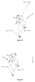
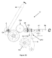
- a first embodiment of a timepiece 1 according to the first aspect of the invention is described below with reference to the Figures 1 to 13 .
- the timepiece is for example a watch, in particular a wristwatch. It comprises a movement 2.
- This movement itself comprises a mechanism 3 for indicating and storing a temporal information, an embodiment of which is described below.
- the timepiece in particular the movement and more particularly the mechanism, has the specificity of selectively indicating a current time information and a stored time information, in particular a stored information of the temporal information. current, by the same display member.
- the control is carried out by the actuation of a single control member 4.
- Such a mechanism 3 of indication and storage can for example be useful for marking a time, a time information, or any information derived from time to the request by a conventional display member normally provided for displaying the current information in question.
- the stored information is represented or indicated by a retrograde system.
- the figure 1 illustrates an embodiment in which a retrograde second-hand storing needle S 'is attached to the conventional second hand S of the timepiece. The movement of the display member S 'here constituted by a storage needle can therefore be retrograde.
- the needle S ' In normal operation, as shown in figure 1 , the needle S ', just like the second hand S, indicates the current second.
- a first action in particular a pressure on the control member 4 as shown in FIG. figure 2 , induces the stopping of the needle S 'without acting on the second hand S which continues its course. In this state, on the timepiece, an indication or a simultaneous display of the current temporal information and the stored time information is then obtained.
- a second action in particular a pressure on the same control member, repositions the needle S 'so that it displays the current second again, as illustrated in FIG. figure 3 .
- the two needles S and S 'are thus synchronized again. Each needle thus displays the current second.
- the lever L1 is kinematically connected to the display member S 'of the time information and the sensor L2 is biased by a second elastic member RL against the cam C.
- the time information relates to the seconds. It can equally well concern the hours, the minutes, or even another unit of magnitude of time.
- the display member may comprise or consist of a needle cooperating with a marking bearing indications and / or graduations.
- counting chain or “counting system” means any device for driving at least the display member.
- the display member is preferably not part of the counting chain.
- a counting chain comprises an accumulator such as a cylinder, a gear wheel, in particular regulated by a balance spring and escapement system.
- the display member By “selectively displaying the current time information and the stored time information”, it is meant that at any time, out of transient phases, the display member indicates either the current time information or the stored time information .
- the transient phases are instantaneous or almost instantaneous. They only last a few fractions of a second, for example less than 0.3 seconds. The display member therefore never comes into a predefined position and independent of time. It follows that the display member permanently performs a function of displaying a temporal information.
- the lever device L is preferably pivoted on a frame 6 of the mechanism, in particular a frame of the movement or the timepiece.
- the cam C is for example a spiral cam. It can be directly carried by a mobile seconds MS in kinematic connection with a second member S for displaying the time information.
- the second display member S can be chased on the mobile of seconds.
- the shape of the cam C is for example such that the first display member S 'performs a retrograde stroke instantaneous return.
- the second display member S may be retrograde or not.
- the lever device L is pivoted along an axis P.
- the lever device comprises two parts: the lever L1 and the sensor L2. Each of these parts is pivoted about the axis P.
- the two parts are connected to each other by a first elastic element such as a return spring R. This first return element allows to recall the lever and the probe in a determined relative position as illustrated in FIG. figure 4 .
- the lever L1 carries a toothing L10 or rake, for example at one of its ends. This toothing is engaged with a pinion PS 'kinematically linked to the display member S'.
- a second storage needle S ' can be driven on the pinion PS'.
- the second part of the lever device comprises a feeler L2 including a probe head L20 which bears against the profile of the cam C under the effect of a second elastic return element RL.
- the lever device behaves like a rigid member. It can therefore be likened to a rigid component pivoted around the axis P.
- the first elastic element R contributes to maintaining the lever and the probe in a predetermined position relative to one another.
- This predetermined position is defined by stops provided on the lever and the probe and cooperating with each other by obstacle in the predetermined position.
- a pin GL2 is driven into the probe L2 and is arranged to abut against a flank FL1 of the lever L1 as shown in FIGS. Figures 4 and 5 .
- the pin could be driven into the lever L1 and cooperate with a side of the lever L2 or another element of the probe.
- a rotation of the cam C in the anti-trigonometric direction induces a rotation of the lever device L in the trigonometric direction so that the toothing L10 can drive the display member S 'in synchronization with the second member.
- display as shown on the Figures 6 to 9 .
- synchronization is meant here that the two display members indicate the same time value. However, their movements may not be identical. In particular, their values of angular displacement velocities can be different.
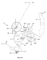
- the mechanism 3 comprises a blocker LB of the lever L1.
- the blocker can be actuated by the control member O, in particular the pusher 4, to selectively position the blocker in a first position leaving the lever L1 free or in a second position blocking or immobilizing the lever L1.
- control member O can actuate the blocker LB via a storage control element RC, such as a cam, in particular a column wheel.
- a storage control element RC such as a cam, in particular a column wheel.
- the blocker can act on an L100 end of the lever L1 and / or can act by friction on the lever L1.
- the blocking or blocking lever LB is positioned so that it can not act on the lever L1 as shown in FIG. figure 10 .
- This blocker LB is for example driven by a storage control element such as a cam which is for example under the shape of a column wheel RC which is indexed angularly by a jumper spring RS.
- a storage control element such as a cam which is for example under the shape of a column wheel RC which is indexed angularly by a jumper spring RS.
- This can be provided with a binary RCa profile which consists of columns and recesses.
- an end LB1 of the LB blocker bears against one of the columns of the cam RC so that an arm LB10 of the LB blocker is out of reach of the end L100 of the lever L1.
- the column wheel RC is also provided with a ratchet gear RCb which is designed to be actuated and driven angularly by an LC control lever under the effect of the control member O, in particular the pusher 4 A pressure on the latter induces the rotation of the column wheel RC so that the end LB1 of the blocker LB moves within a hollow of the column wheel under the effect of a return spring. RLB.
- the LB10 arm of the blocker LB prints a force F against the oriented end L100, in particular as a function of the coefficient of friction f at the interface of the arm LB10 and the end of the lever L1, so that the lever L1 is immobilized or locked in rotation around the axis P.
- the feeler L2 can turn on its axis P under the effect of the rotation of the cam C. This rotation is done at against the first elastic element R which deforms. This situation results in immobilization of the display member S ', while the second display member S continues its course.
- a new pressure on the control member O repositions the column wheel RC in a configuration similar to that of the figure 10 .
- the LB10 arm of the LB blocker then deviates from the L100 end of the lever L1 against the effect of the RLB spring.
- the lever L1 is released and, under the effect of the first elastic element R, is then repositioned so that its flank FL1 comes into abutment against the pin GL2 of the L2 probe.
- the lever device L thus resumes its configuration as shown in FIGS. Figures 8 to 10 .
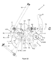
- the mechanism 3 may comprise an isolation device LI arranged to have a first position in which the probe L2 is kinematically connected to the counting chain of the time information and a second position in which the L2 probe is disconnected from the time information counting chain.
- the probe L2 bears against the cam C and, in a second position, the sensor L2 is disconnected from the cam C or kept at a distance from the cam C.
- the isolation device is arranged to act on an end L200 of the sensor L2, in particular to act by contact.
- the isolation device and the blocker are kinematically connected, even integral or fixed to each other.
- the isolation device can be in a first position when the blocker is in its first position and the isolation device is in a second position when the blocker is in its second position.
- an isolation device LI is thus added to the blocker LB so as to release the probe L2 from the path of the cam C when the blocker LB immobilizes the lever L1.
- the isolation device LI works in synchronization with the blocker LB by means of the column wheel RC.
- the figures 12 and 13 illustrate such an isolation device.
- the isolation device LI comprising an isolation lever LI1 and an elastic element RLI such as a spring, is positioned so that it can not act on the feeler of the lever device L, just as the LB blocker. More particularly, an end LI10 of the isolation device LI is located in a recess RCa of the RC cam under the effect of a spring RLI so that a flank LI100 of the isolation device LI is located out of reach of the L200 edge of the L2 probe.
- the flank LI100 of the isolation device LI bears against the flank L200 of the probe L2 against the springs R and RL, while the end L100 of the lever L1 is immobilized beforehand by the arm LB10 of the blocker LB.
- the motor member of the movement of the timepiece, through the cam C opposes the maximum torque produced by the spring RL. This maximum opposition is encountered in the synchronization situation of the display members.
- the isolation device is connected to the control member O, in particular to a push button 4, the control member being itself connected to the blocker LB.
- the control member makes it possible to simultaneously control the change of position of the blocker and the isolation device.
- control member may comprise an actuating element of the isolation device via a storage control element RC, in particular the column wheel, which actuates the blocker LB.
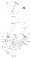
- a second embodiment of a timepiece 1 'according to the second aspect of the invention is described below with reference to the Figures 14 to 22 .
- the timepiece is for example a watch, in particular a wristwatch. It includes a 2 'movement. This movement itself comprises a mechanism 3 'of correction of a display device of a temporal information as described below.
- the correction mechanism provides bi-directional correction for a time-based or time-derived information display device or bi-directional correction of a time-based or time-based information display device.
- Such a mechanism is in particular adapted to correct in both correction directions a temporal or time-derived indication which can be memorized by a display and storage device according to the first aspect of the invention.
- the information to be corrected is indicated in a retrograde manner, in particular in a retrograde manner with instant feedback.
- retrograde display we mean any display capable of implementing a display member capable of pivoting in two directions of rotation. Instead of performing a complete revolution, the display member makes a path from a starting point A to an arrival point B in front of a graduation representing, for example, a magnitude related to time. Once the path from A to B has been achieved, the indicator member can in particular return back to point A instantaneously.
- the display members may comprise or consist of needles.
- a spiral-shaped cam makes it possible to display the information and to guarantee the return instantaneous display member M 'in a predetermined position through the lever device L and the return spring RL.
- This cam is kinematically linked to the display system of the current time, so that it is rotated during a forward and reverse correction of this current display.
- the geometry of this cam characterized by the presence of an abrupt flank to allow the instantaneous return of the lever device and therefore the display member M ', poses a problem during a rearward correction. Indeed, correction in the counterclockwise direction is not possible when the probe of the lever device reaches the height of the steep side of the cam. This configuration therefore induces a blockage that may lead to the deterioration or even the breakage of elements.
- the mechanism 3 ' like the variants of the mechanism 3 represented on the figures 12 and 13 , includes a disengagement system connected to the retrograde system that disconnects the probe from the cam.
- this system also allows a bidirectional rotation of the cam during the adjustment operation of the time information.
- This release system has the specificity of acting directly on the retrograde lever device L, in particular by a rotational movement of the isolation device. Indeed, such a configuration makes it possible to advantageously interact the correction and storage functions of the time information. Another advantage lies in the fact that it minimizes the number of components required when it comes to multiplying the correction mechanisms.
- correction mechanisms according to the second aspect of the invention make it possible to remedy the aforementioned defects. Indeed, they are operable at any time, that is to say, even when a temporal information is stored.
- the mechanism 3 'of correction of a display device of a temporal information comprises a first member M for displaying a first time information and a second member M' for displaying the first information stored.
- the mechanism includes an isolation device of the first and second display members.
- the second display member M ' indicates for example the current minute.
- the second display member M ' is positioned in a predetermined position while a bidirectional rotation of the control ring causes a drive of the first display member M in the both directions.
- the predetermined position is preferably invariant in time.
- the second display member In memorization phase as shown on the figure 16 under the actuation of the control member O, the second display member is stopped while the first display member continues its course. In this configuration as shown on the figure 17 , the adjusting ring CR has no effect on the second display member M 'which remains in its position as defined by the control member O. A bidirectional rotation of the adjusting ring CR then generates a drive in the two directions of rotation of the first display member M.
- the isolation device has a first configuration in which the positions of the first and second members are linked and a second configuration in which the positions of the first and second members are independent.
- the mechanism 3 ' may comprise, as in the first embodiment, a spiral cam C directly carried by a CH surface on which is fixed, in particular driven, the first display member.
- the second display member M ' is moved by a retrograde system similar to that described in the first embodiment.
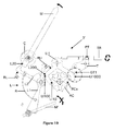
- the isolation device can be shaped so that it can be actuated by a pull tab T of the correction mechanism and by an RC cam of the storage mechanism.
- the isolation device In normal operation as shown in figure 18 that is, when the first and second display members are linked or synchronized, the isolation device is in the first configuration. More particularly, the isolation device is shaped or arranged so as to be out of reach of the retrograde lever device L. More particularly, an end LI10 of the isolation device LI is located in a hollow of the binary profile RCa of the RC cam under the effect of a spring RLI so that a flank LI100 of the isolation device LI is out of range of a flank L200 of the probe L2.
- the isolation device LI may be actuated by a correction element, in particular a rod TR or a pull tab T, for selectively positioning the probe L2 in a first position defined by the first configuration of the isolation device LI and in a second position defined by the second configuration of the isolation device.
- a correction element in particular a rod TR or a pull tab T
- the actuation of the isolation device LI by the correction element can induce the rotation of the lever device L10.
- the isolation device and the correction element can be arranged so that the actuation of the isolation device LI by the correction element induces the positioning of the second display member M 'in a position predefined, especially in an extreme position or stop. This position can indicate to the user the correction status.
- the display In the storage phase, the display can also be corrected. In this case, the second member M 'remains in the position that is stored.
- control member O and the isolation device LI are advantageously arranged so that the control member can actuate the isolation device. In particular, this actuation is performed via the storage control element RC.
- the isolation device is in the first configuration unless the controller or correction element is in a condition conditioning the second configuration of the isolation device.
- the "Or” preceding is an “inclusive”, that is to say that it is sufficient that at least one of the control member and the correction element is in a state conditioning the second configuration of the isolation device, so that the isolation device is in this second configuration. If each of the control member and the correction element is in a condition conditioning the second configuration of the isolation device, the isolation device is a fortiori in this second configuration.
- a flank LI1000 of the isolation device is located opposite a pin GT1 of the zipper T.
- a traction of the adjustment rod TR induces the pivoting of the isolation device through the pin GT1 which just press the flank LI1000 of the isolation device.
- the flank LI100 of the isolating device LI thus actuates the flank L200 of the lever device L, which positions the lever device L against the return spring RL in an angular position determined so as to release the probe L20 from the path of the cam C.
- a bidirectional rotation of the cam C is thus allowed.
- the kinematic chain CM intended to correct the display indicated by the first member display M can therefore be driven in both directions of rotation as shown in FIG. figure 19 .
- the drive train CM can be activated under the effect of a pin GT2 of the pull tab T. In setting position, this chain positions a rocker B against a spring RB so as to engage the driveline CM by through the front teeth DF of a sliding pinion PC as shown on the figure 20 .
- the isolation device LI is arranged to release the probe L20 from the path of the cam C under the effect of the RC control cam. More particularly, the end LI10 of the isolation device LI bears against one of the columns of the cam RC so that the flank LI100 lifts the flank L200 of the lever L2 against the actions of the R and RL springs. In this configuration, the pin GT1 of the pull tab T is out of range of the LI1000 flank of the isolation device LI.
- a traction of the adjustment rod TR has no effect on the isolation device LI which is previously positioned so that the probe L20 is clear of the path of the cam C.
- a bidirectional rotation of the cam C is thus allowed.
- the kinematic chain CM intended to correct the display indicated by the first display member M can therefore be driven in both directions of rotation as shown in FIG. figure 22 .
- the probe L2 in the first position of the isolation device LI, is arranged to bear against the cam C connected to the first display member M under the effect of the second element elastic. In a second position of the isolation device LI, the probe L2 can be arranged to be disconnected from the cam C, is kept away from the cam.
- the isolation device LI may comprise the isolation lever LI1 capable of acting or arranged to act on the lever device L pivoted and including the lever L1, the feeler L2 and the first elastic member R recalling the lever L1 and the probe L2 in a determined relative position.
- the lever L1 is kinematically connected to the second display member M '.
- the isolation device, the correction element and the probe are arranged so that the probe is positioned in the second position by the correction element TR, T when the blocker LB is in a first position leaving the lever L1 free. .
- the blocker LB can cooperate with the RC storage control element to selectively position the blocker in a first position leaving the lever L1 free or in a second position blocking the lever L1.
- the isolation device LI may be arranged to act on an end L200 of the probe L2 and / or to act by obstacle on the probe.
- the configuration, including the position, of the correction element and the configuration, including the position, of the storage control element determine the configuration, including the position, of the isolation device.
- the configuration, including the position, of the isolation device, and the configuration, including the position, of the storage control element determines the configuration, including the position, of the probe.
- correction devices can be associated to correct more than one temporal information, including information that is kinematically related to each other, for example the indications of hours and minutes.
- these devices can be controlled by a single pull tab T and a single control cam RC so as to drive in synchronization isolation levers specific to each of the display members of the stored time information.
- the isolation levers LI and the pull tab T may form a single kinematic chain.
- the blocker could be actuated directly by a control element such as a pusher, without implementing a column wheel.
- a control element such as a pusher
- the stored information can be displayed only when the user acts on the control element.
- the blocker LB can be arranged so that it can lock the lever L1 regardless of the position of the lever L1 in "memorizing" phase. In other words, in the phase of storage ", the blocker LB can be arranged so that it can stop the display member S 'regardless of the position of the display member S'.
- the lever device L can be manufactured in one piece or be monobloc.
- the first elastic element R is formed by an elastically deformable part, in particular an elastically deformable part separating the lever L1 and the probe L2.
- "storage of a temporal information” preferably means an action of storing a temporal information.
- This storage action is preferably triggered by an action of the user.
- This storage action preferably relates to the storage of current or instantaneous time information during the action of the user.
- new temporal information can be stored.
- the display of this stored time information can be maintained.
- the storage of a temporal information may consist in freezing the current or instantaneous temporal information. Other members may continue to display the current time information when some are frozen or blocked to indicate the stored time information.
- the first elastic element and the second elastic element are distinct.
- the probe L2 can be articulated or pivoted on the lever L1.
- a positioning of display members in one or more random positions or defined once and for all, that is to say in one or more positions that are not definable or non-modifiable by the user, as can be found in mechanisms display on demand, does not constitute a storage within the meaning of the invention.
Landscapes
- Physics & Mathematics (AREA)
- General Physics & Mathematics (AREA)
- Geometry (AREA)
- Measurement Of Unknown Time Intervals (AREA)
- Electromechanical Clocks (AREA)
- Time Recorders, Dirve Recorders, Access Control (AREA)
Priority Applications (1)
| Application Number | Priority Date | Filing Date | Title |
|---|---|---|---|
| EP14176314.4A EP2824521A3 (de) | 2013-07-12 | 2014-07-09 | Uhrmechanismus, Uhrwerk und Uhr |
Applications Claiming Priority (2)
| Application Number | Priority Date | Filing Date | Title |
|---|---|---|---|
| EP13176381 | 2013-07-12 | ||
| EP14176314.4A EP2824521A3 (de) | 2013-07-12 | 2014-07-09 | Uhrmechanismus, Uhrwerk und Uhr |
Publications (2)
| Publication Number | Publication Date |
|---|---|
| EP2824521A2 true EP2824521A2 (de) | 2015-01-14 |
| EP2824521A3 EP2824521A3 (de) | 2016-06-01 |
Family
ID=48783073
Family Applications (1)
| Application Number | Title | Priority Date | Filing Date |
|---|---|---|---|
| EP14176314.4A Pending EP2824521A3 (de) | 2013-07-12 | 2014-07-09 | Uhrmechanismus, Uhrwerk und Uhr |
Country Status (4)
| Country | Link |
|---|---|
| US (1) | US9239570B2 (de) |
| EP (1) | EP2824521A3 (de) |
| JP (1) | JP6469978B2 (de) |
| CN (1) | CN104281042B (de) |
Cited By (2)
| Publication number | Priority date | Publication date | Assignee | Title |
|---|---|---|---|---|
| EP3208665A1 (de) * | 2016-02-18 | 2017-08-23 | Blancpain SA. | Retrograde anzeige einer uhr mit einziehbarem zeiger |
| CH713354A1 (fr) * | 2017-01-13 | 2018-07-13 | Mft Et Fabrique De Montres Et Chronometres Ulysse Nardin Le Locle S A | Mécanisme pour pièce d'horlogerie comportant une came et un palpeur, notamment pour montre régate ou montre à sonnerie. |
Families Citing this family (11)
| Publication number | Priority date | Publication date | Assignee | Title |
|---|---|---|---|---|
| EP3059643B1 (de) * | 2015-02-23 | 2017-07-19 | Montres Breguet S.A. | Uhrmechanismus |
| EP3185090B1 (de) * | 2015-12-23 | 2019-10-23 | Rolex Sa | Zähler- und anzeigevorrichtung einer fraktion einer zeiteinheit |
| CH712217A2 (fr) * | 2016-03-15 | 2017-09-15 | Chanel Sa Genève | Mouvement de montre comportant un affichage rétrograde et un anneau des heures sautant. |
| EP3410231B1 (de) * | 2017-05-29 | 2021-06-30 | Montres Breguet S.A. | Uhrwerksmechanismus |
| EP3486735B1 (de) * | 2017-11-20 | 2020-09-30 | Montres Breguet S.A. | Uhrwerksmechanismus zur nullrückstellung der sekunde mit schneckennocken |
| EP3489766A1 (de) * | 2017-11-27 | 2019-05-29 | Montres Breguet S.A. | Mechanismus zur korrektur einer bewegungsfunktion einer uhr |
| JP7473300B2 (ja) * | 2018-04-30 | 2024-04-23 | ロレックス・ソシエテ・アノニム | 時計表示システム |
| EP3605243A1 (de) * | 2018-07-31 | 2020-02-05 | Montres Breguet S.A. | Uhr-anzeigemechanismus mit variabler geometrie und elastischem zeiger |
| EP3637197B1 (de) * | 2018-10-12 | 2021-05-19 | Blancpain SA | Vorrichtung zur regulierung der retrograden anzeige einer uhr |
| USD924713S1 (en) * | 2018-12-05 | 2021-07-13 | Richemont International Sa | Watch dial |
| EP3869280B1 (de) * | 2020-02-19 | 2024-04-17 | Montres Breguet S.A. | Anzeigemechanismus für uhr |
Citations (5)
| Publication number | Priority date | Publication date | Assignee | Title |
|---|---|---|---|---|
| EP0851321A2 (de) | 1996-12-26 | 1998-07-01 | Seiko Instruments Inc. | Mehrzweckuhr |
| EP1475681A1 (de) | 2003-05-09 | 2004-11-10 | Audemars Piguet (Renaud et Papi) SA | Chronographuhr mit sofortiger Anzeige von Sekunden-Bruchteilen |
| EP1918792A1 (de) | 2006-11-06 | 2008-05-07 | Compagnie des Montres Longines, Francillon SA | Uhr, die einen Korrekturmechanismus für eine Vorrichtung zur Anzeige einer Zeitgröße umfasst |
| EP2159652A1 (de) | 2008-08-26 | 2010-03-03 | Agenhor SA | Anzeigemechanismus für Uhr, der die Anzeige sowie das Ausblenden der aktuellen Uhrzeit ermöglicht |
| CH700902A2 (de) | 2009-04-27 | 2010-10-29 | Seiko Instr Inc | Uhr mit Datumsanzeige und einer Funktion zur Anzeige von AM/PM (Vormittag/Nachmittag). |
Family Cites Families (16)
| Publication number | Priority date | Publication date | Assignee | Title |
|---|---|---|---|---|
| US256418A (en) * | 1882-04-11 | Half to john james hanhaet | ||
| US2909892A (en) * | 1957-06-14 | 1959-10-27 | Longines Wittnauer Watch Co In | Electric watch movement |
| DE60029423T2 (de) | 2000-05-05 | 2006-11-30 | Rolex Sa | Uhr mit Aufzugsmechanismus und mit Korrekturmechanismus für mindestens zwei anzeigende Organe |
| JP4386022B2 (ja) | 2004-11-10 | 2009-12-16 | セイコーエプソン株式会社 | 時計の表示装置、ムーブメント、および時計 |
| US7961560B2 (en) | 2005-01-24 | 2011-06-14 | Seiko Epson Corporation | Display device for timepiece, movement, and timepiece |
| EP1708052B1 (de) | 2005-03-31 | 2008-05-14 | MONTRES CORUM Sàrl | Uhrwerk |
| DE05405596T1 (de) | 2005-10-21 | 2007-10-11 | Rolex Sa | Uhr mit einem Mechanismus zur Messung von einstellbaren vorbestimmten Zeitdauern |
| CH698826B1 (fr) | 2006-03-29 | 2009-11-13 | Girard Perregaux Sa | Mouvement pour pièce d'horlogerie à affichage rétrograde. |
| DE602006005827D1 (de) | 2006-12-13 | 2009-04-30 | Montres Breguet Sa | asst |
| US7782717B2 (en) * | 2006-12-23 | 2010-08-24 | Franck Müller Watchland S.A. | On-demand display device for a timepiece |
| CH705056B1 (fr) | 2008-02-08 | 2012-12-14 | Manuf La Joux Perret Sa | Pièce d'horlogerie comportant un mécanisme de chronographe. |
| CH703470A2 (fr) | 2010-07-21 | 2012-01-31 | Blancpain Sa | Pièce d'horlogerie à double affichage. |
| FR2973125B1 (fr) * | 2011-03-23 | 2013-05-10 | Samep Montres Emile Pequignet | Support pour organe d'affichage de mouvement horloger |
| CH704696B1 (fr) * | 2011-03-25 | 2016-10-31 | Chronode Sa | Pièce d'horlogerie comportant un mécanisme d'affichage rétrograde. |
| US9146541B2 (en) | 2011-06-29 | 2015-09-29 | Rolex S.A. | Device for resetting to a predetermined position an indicator member indicative of a parameter connected with time |
| EP2595006B1 (de) * | 2011-11-17 | 2017-11-01 | Blancpain S.A. | Mechanische Anzeigevorrichtung für die Zustandsveränderung eines halbschnell oder schnell weiter springenden Anzeigemechanismus |
-
2014
- 2014-07-09 EP EP14176314.4A patent/EP2824521A3/de active Pending
- 2014-07-10 US US14/328,282 patent/US9239570B2/en active Active
- 2014-07-10 JP JP2014141886A patent/JP6469978B2/ja active Active
- 2014-07-14 CN CN201410334540.3A patent/CN104281042B/zh active Active
Patent Citations (5)
| Publication number | Priority date | Publication date | Assignee | Title |
|---|---|---|---|---|
| EP0851321A2 (de) | 1996-12-26 | 1998-07-01 | Seiko Instruments Inc. | Mehrzweckuhr |
| EP1475681A1 (de) | 2003-05-09 | 2004-11-10 | Audemars Piguet (Renaud et Papi) SA | Chronographuhr mit sofortiger Anzeige von Sekunden-Bruchteilen |
| EP1918792A1 (de) | 2006-11-06 | 2008-05-07 | Compagnie des Montres Longines, Francillon SA | Uhr, die einen Korrekturmechanismus für eine Vorrichtung zur Anzeige einer Zeitgröße umfasst |
| EP2159652A1 (de) | 2008-08-26 | 2010-03-03 | Agenhor SA | Anzeigemechanismus für Uhr, der die Anzeige sowie das Ausblenden der aktuellen Uhrzeit ermöglicht |
| CH700902A2 (de) | 2009-04-27 | 2010-10-29 | Seiko Instr Inc | Uhr mit Datumsanzeige und einer Funktion zur Anzeige von AM/PM (Vormittag/Nachmittag). |
Cited By (4)
| Publication number | Priority date | Publication date | Assignee | Title |
|---|---|---|---|---|
| EP3208665A1 (de) * | 2016-02-18 | 2017-08-23 | Blancpain SA. | Retrograde anzeige einer uhr mit einziehbarem zeiger |
| US10222749B2 (en) | 2016-02-18 | 2019-03-05 | Blancpain Sa | Retrograde timepiece display with a retractable hand |
| CH713354A1 (fr) * | 2017-01-13 | 2018-07-13 | Mft Et Fabrique De Montres Et Chronometres Ulysse Nardin Le Locle S A | Mécanisme pour pièce d'horlogerie comportant une came et un palpeur, notamment pour montre régate ou montre à sonnerie. |
| EP3349072A1 (de) * | 2017-01-13 | 2018-07-18 | Manufacture et fabrique de montres et chronomètres, Ulysse Nardin Le Locle S.A. | Mechanismus für uhr, der einen nocken und einen taster umfasst |
Also Published As
| Publication number | Publication date |
|---|---|
| JP2015017985A (ja) | 2015-01-29 |
| JP6469978B2 (ja) | 2019-02-13 |
| CN104281042B (zh) | 2019-06-21 |
| US9239570B2 (en) | 2016-01-19 |
| US20150016232A1 (en) | 2015-01-15 |
| EP2824521A3 (de) | 2016-06-01 |
| CN104281042A (zh) | 2015-01-14 |
Similar Documents
| Publication | Publication Date | Title |
|---|---|---|
| EP2824521A2 (de) | Uhrmechanismus, Uhrwerk und Uhr | |
| EP2950165B1 (de) | Schnellkorrektursystem einer kalenderdateninformation | |
| EP1918792B1 (de) | Uhr, die einen Korrekturmechanismus für eine Vorrichtung zur Anzeige einer Zeitgröße umfasst | |
| EP2115537B1 (de) | Zeitmessgerät mit einem mechanismus zum betrieb einer vorrichtung zur anzeige eines zeitbezogenen wertes | |
| EP1777598B1 (de) | Uhr mit einem Mechanismus zur Messung von einstellbaren vorbestimmten Zeitdauern | |
| EP2565729A1 (de) | Kalendermechanismus | |
| EP1936448A2 (de) | Uhranzeigevorrichtung, die auf Wunsch aktiviert wird | |
| EP2824517A2 (de) | Uhrmechanismus, Uhrwerk und Uhr | |
| EP2784603B1 (de) | Vorrichtung zur Anzeige einer Zeitinformation | |
| WO2014095728A1 (fr) | Piece d'horlogerie a affichage de l'heure universelle | |
| EP2811347B1 (de) | Uhrmechanismus zur Speicherung und Anzeige einer Zeitanzeige | |
| EP1792235B1 (de) | Kalenderuhr mit zeitgleichungsvorrichtung | |
| CH703361A2 (fr) | Mouvement horloger presentant des fonctions de chronographe et de compte-a-rebours. | |
| EP3333641B1 (de) | Uhrwerksmechanismus zur steuerung einer vielzahl von anzeigen | |
| CH699785B1 (fr) | Pièce d'horlogerie à fuseaux horaires et à quantième. | |
| EP2811348B1 (de) | Uhrmechanismus zur speicherung und anzeige einer zeitanzeige | |
| WO1998044394A1 (fr) | Mecanisme de mise a l'heure d'un mouvement d'horlogerie a quantieme perpetuel | |
| EP3173877A1 (de) | Kalendersystem für uhr | |
| EP2821862A2 (de) | Uhr | |
| CH711073A2 (fr) | Mécanisme d'affichage du numéro de la semaine pour pièce d'horlogerie. | |
| WO2019180119A1 (fr) | Système horloger de transmission | |
| EP4012505A1 (de) | Uhrvorrichtung mit antiblockiervorrichtung | |
| CH706651A2 (fr) | Système d'indication d'une information et pièce d'horlogerie comprenant un tel système. | |
| CH709712A2 (fr) | Système de correction rapide d'une information, notamment une information horaire. | |
| CH716150A1 (fr) | Mécanisme horloger de blocage d'un mobile sautant et mouvement pour montre chronographe le comprenant. |
Legal Events
| Date | Code | Title | Description |
|---|---|---|---|
| 17P | Request for examination filed |
Effective date: 20140709 |
|
| AK | Designated contracting states |
Kind code of ref document: A2 Designated state(s): AL AT BE BG CH CY CZ DE DK EE ES FI FR GB GR HR HU IE IS IT LI LT LU LV MC MK MT NL NO PL PT RO RS SE SI SK SM TR |
|
| AX | Request for extension of the european patent |
Extension state: BA ME |
|
| PUAI | Public reference made under article 153(3) epc to a published international application that has entered the european phase |
Free format text: ORIGINAL CODE: 0009012 |
|
| PUAL | Search report despatched |
Free format text: ORIGINAL CODE: 0009013 |
|
| AK | Designated contracting states |
Kind code of ref document: A3 Designated state(s): AL AT BE BG CH CY CZ DE DK EE ES FI FR GB GR HR HU IE IS IT LI LT LU LV MC MK MT NL NO PL PT RO RS SE SI SK SM TR |
|
| AX | Request for extension of the european patent |
Extension state: BA ME |
|
| RIC1 | Information provided on ipc code assigned before grant |
Ipc: G04F 7/08 20060101AFI20160425BHEP Ipc: G04B 19/08 20060101ALI20160425BHEP Ipc: G04B 19/02 20060101ALI20160425BHEP |
|
| STAA | Information on the status of an ep patent application or granted ep patent |
Free format text: STATUS: REQUEST FOR EXAMINATION WAS MADE |
|
| R17P | Request for examination filed (corrected) |
Effective date: 20161201 |
|
| RBV | Designated contracting states (corrected) |
Designated state(s): AL AT BE BG CH CY CZ DE DK EE ES FI FR GB GR HR HU IE IS IT LI LT LU LV MC MK MT NL NO PL PT RO RS SE SI SK SM TR |
|
| STAA | Information on the status of an ep patent application or granted ep patent |
Free format text: STATUS: EXAMINATION IS IN PROGRESS |
|
| 17Q | First examination report despatched |
Effective date: 20210520 |
|
| STAA | Information on the status of an ep patent application or granted ep patent |
Free format text: STATUS: EXAMINATION IS IN PROGRESS |
|
| P01 | Opt-out of the competence of the unified patent court (upc) registered |
Effective date: 20230530 |