EP2824348A2 - Reibkupplung - Google Patents
Reibkupplung Download PDFInfo
- Publication number
- EP2824348A2 EP2824348A2 EP14175420.0A EP14175420A EP2824348A2 EP 2824348 A2 EP2824348 A2 EP 2824348A2 EP 14175420 A EP14175420 A EP 14175420A EP 2824348 A2 EP2824348 A2 EP 2824348A2
- Authority
- EP
- European Patent Office
- Prior art keywords
- friction
- friction clutch
- cooling liquid
- coupling device
- clutch
- Prior art date
- Legal status (The legal status is an assumption and is not a legal conclusion. Google has not performed a legal analysis and makes no representation as to the accuracy of the status listed.)
- Granted
Links
Images


Classifications
-
- F—MECHANICAL ENGINEERING; LIGHTING; HEATING; WEAPONS; BLASTING
- F16—ENGINEERING ELEMENTS AND UNITS; GENERAL MEASURES FOR PRODUCING AND MAINTAINING EFFECTIVE FUNCTIONING OF MACHINES OR INSTALLATIONS; THERMAL INSULATION IN GENERAL
- F16D—COUPLINGS FOR TRANSMITTING ROTATION; CLUTCHES; BRAKES
- F16D25/00—Fluid-actuated clutches
- F16D25/06—Fluid-actuated clutches in which the fluid actuates a piston incorporated in, i.e. rotating with the clutch
- F16D25/062—Fluid-actuated clutches in which the fluid actuates a piston incorporated in, i.e. rotating with the clutch the clutch having friction surfaces
- F16D25/063—Fluid-actuated clutches in which the fluid actuates a piston incorporated in, i.e. rotating with the clutch the clutch having friction surfaces with clutch members exclusively moving axially
- F16D25/0635—Fluid-actuated clutches in which the fluid actuates a piston incorporated in, i.e. rotating with the clutch the clutch having friction surfaces with clutch members exclusively moving axially with flat friction surfaces, e.g. discs
- F16D25/0638—Fluid-actuated clutches in which the fluid actuates a piston incorporated in, i.e. rotating with the clutch the clutch having friction surfaces with clutch members exclusively moving axially with flat friction surfaces, e.g. discs with more than two discs, e.g. multiple lamellae
-
- F—MECHANICAL ENGINEERING; LIGHTING; HEATING; WEAPONS; BLASTING
- F16—ENGINEERING ELEMENTS AND UNITS; GENERAL MEASURES FOR PRODUCING AND MAINTAINING EFFECTIVE FUNCTIONING OF MACHINES OR INSTALLATIONS; THERMAL INSULATION IN GENERAL
- F16D—COUPLINGS FOR TRANSMITTING ROTATION; CLUTCHES; BRAKES
- F16D13/00—Friction clutches
- F16D13/22—Friction clutches with axially-movable clutching members
- F16D13/38—Friction clutches with axially-movable clutching members with flat clutching surfaces, e.g. discs
- F16D13/52—Clutches with multiple lamellae ; Clutches in which three or more axially moveable members are fixed alternately to the shafts to be coupled and are pressed from one side towards an axially-located member
-
- F—MECHANICAL ENGINEERING; LIGHTING; HEATING; WEAPONS; BLASTING
- F16—ENGINEERING ELEMENTS AND UNITS; GENERAL MEASURES FOR PRODUCING AND MAINTAINING EFFECTIVE FUNCTIONING OF MACHINES OR INSTALLATIONS; THERMAL INSULATION IN GENERAL
- F16D—COUPLINGS FOR TRANSMITTING ROTATION; CLUTCHES; BRAKES
- F16D13/00—Friction clutches
- F16D13/58—Details
- F16D13/72—Features relating to cooling
-
- F—MECHANICAL ENGINEERING; LIGHTING; HEATING; WEAPONS; BLASTING
- F16—ENGINEERING ELEMENTS AND UNITS; GENERAL MEASURES FOR PRODUCING AND MAINTAINING EFFECTIVE FUNCTIONING OF MACHINES OR INSTALLATIONS; THERMAL INSULATION IN GENERAL
- F16D—COUPLINGS FOR TRANSMITTING ROTATION; CLUTCHES; BRAKES
- F16D25/00—Fluid-actuated clutches
- F16D25/12—Details not specific to one of the before-mentioned types
- F16D25/123—Details not specific to one of the before-mentioned types in view of cooling and lubrication
-
- F—MECHANICAL ENGINEERING; LIGHTING; HEATING; WEAPONS; BLASTING
- F16—ENGINEERING ELEMENTS AND UNITS; GENERAL MEASURES FOR PRODUCING AND MAINTAINING EFFECTIVE FUNCTIONING OF MACHINES OR INSTALLATIONS; THERMAL INSULATION IN GENERAL
- F16D—COUPLINGS FOR TRANSMITTING ROTATION; CLUTCHES; BRAKES
- F16D2300/00—Special features for couplings or clutches
- F16D2300/06—Lubrication details not provided for in group F16D13/74
-
- F—MECHANICAL ENGINEERING; LIGHTING; HEATING; WEAPONS; BLASTING
- F16—ENGINEERING ELEMENTS AND UNITS; GENERAL MEASURES FOR PRODUCING AND MAINTAINING EFFECTIVE FUNCTIONING OF MACHINES OR INSTALLATIONS; THERMAL INSULATION IN GENERAL
- F16D—COUPLINGS FOR TRANSMITTING ROTATION; CLUTCHES; BRAKES
- F16D2500/00—External control of clutches by electric or electronic means
- F16D2500/70—Details about the implementation of the control system
- F16D2500/704—Output parameters from the control unit; Target parameters to be controlled
- F16D2500/70446—Clutch cooling parameters
- F16D2500/70448—Clutch cooling parameters for regulating the amount of fluid flow
- F16D2500/7045—On/off switching of the cooling fluid flow
Definitions
- the invention relates to a friction clutch comprising an input side and an output side, which are arranged rotatably about an axis of rotation, and a wet space which can be filled with a cooling liquid, wherein in the wet space, a first friction partner, which is connected torque-locked to the input side, a second friction partner , which is torque-connected to the output side, and a compression means, which is designed to provide an axial compression of the first friction partner and the second friction partner for generating a torque closure between the input side and the output side are arranged.
- From the DE 10 2012 208 579 A1 is a torque transmitting device in a drive train of a motor vehicle having a rotatable about an axis of rotation and housed in a housing coupling device with a friction region for frictional connection of a drive side with a driven side and provided for supplying fluid into the housing first passage opening and one for the outflow of fluid the second passage opening provided in the housing and a first cooling fluid flow passing through the first and second openings for cooling the friction area, wherein the friction area is traversed by a second flow of cooling fluid circulating in the housing, primarily bypassing a passage through the first and second passages second passage opening.
- an improved friction clutch can be provided in that the friction clutch comprises an input side and an output side, which are arranged rotatably about an axis of rotation. Furthermore, the friction clutch comprises a wet space which can be filled with a cooling liquid. In the wet space is a first friction partner, which is torque-tightly connected to the input side, and a second friction partner, which is torque-connected to the output side, and a compression device arranged, which is adapted to provide an axial compression of the first Reibpartners and the second Reibpartners for generating a torque closure between the input side and the output side. Furthermore, a braking device for the cooling liquid is provided in the wet space, which is arranged axially adjacent to the first and / or the second friction partner. The braking device is designed to reduce a peripheral speed of the cooling liquid.
- the braking device comprises a carrier disk. On the carrier disk, a brake structure is provided. The brake structure is arranged on one of the first and / or second friction partner facing end side of the carrier disk. In this way, a braking device which is particularly compact in the axial direction is provided, so that overall the friction clutch requires a small axial installation space.
- the brake structure comprises at least one blade.
- the blade is in particular arranged obliquely or perpendicular to a tangent to the carrier disk, so that the blade promotes the coolant radially inward.
- the peripheral speed of the cooling fluid emerging between the friction partners can be reduced to a particularly high degree and, in particular, if the blade is arranged at an angle to the tangent to the carrier disk, the coolant can be conveyed radially inwards particularly well by means of the peripheral speed. Thereby, the circulation of the cooling liquid within the friction clutch can be further increased.
- a coupling device comprising at least a first and a second switching state.
- the coupling device connects the braking device in a torque-locking manner with another component of the friction clutch.
- the coupling device is disengaged in order to at least partially interrupt a torque transmission between the braking device and the further component.
- the braking device can be controlled.
- the circulation of the cooling liquid can be controlled depending on the operating state of the friction clutch and the load of the friction partners, so that in addition to an operating state with high circulation of the cooling liquid and a low-circulation operating state, in which the deceleration z. B. runs along freely in the flow of the coolant, can be provided.
- the temperature of the friction partners can be kept low and on the other hand the efficiency of the friction clutch can be increased.
- the further component is the output side of the friction clutch or a rotationally fixed component of a drive train, in particular a Leitradstutzen a hydrodynamic converter.
- a control device is provided, which is designed to control the clutch device for switching the at least two switching states.
- control device is designed to detect a temperature of the cooling liquid and / or at least one friction partner and / or a travel path of the compression device, wherein when exceeding or falling below a predefined threshold value of the detected temperature of the cooling liquid and / or the at least one Reibpartners and / or the travel, the control device controls the coupling device for changing the switching state of the coupling device.
- control device comprises a time measuring device, wherein the time measuring device is designed to start a time detection when the threshold value is exceeded, and wherein the control device is designed, at the end of a predefined time interval detected by the time measuring device, the coupling device to control the change of the switching state of the coupling device.
- the compression device has a first pressure piston and a first pressure chamber delimited by the first pressure piston.
- the coupling device has a second pressure piston which limits a second pressure chamber.
- the first and the second pressure chamber can be filled with a pressure oil.
- the second pressure piston is designed to be displaced by means of the pressure oil in order to provide a torque closure between the braking device and the further component.
- the first and the second pressure chamber are fluidly connected via a connecting channel.
- a control valve of the control device is arranged in the connecting channel, which is designed to open and close the connecting channel, wherein in particular the control valve is designed as a temperature-sensitive valve. In this way it is ensured that the coupling device is controlled synchronously with the compression device by the fluidic connection via the connecting channel.
- the coupling device in the first switching state, can be connected to the output side in a torque-locking manner.
- the compression device provides torque closure between the input and output sides when pressure is applied to the pressure oil.
- the coupling device is disengaged so that the braking device can rotate freely with the cooling liquid.
- the cooling liquid is decelerated by the deceleration device during engagement and simultaneously provided a high circulation, whereas in the engaged state of the friction clutch, the efficiency of the friction clutch by reducing the circulation, since the deceleration device is disengaged increased.
- the compression device comprises a piston and a pressure chamber which is delimited by the piston.
- the pressure chamber can be filled with a pressure oil in order to displace the piston axially and to axially compress the friction partners, the piston having an end face on a face remote from the pressure chamber having a connecting element which couples the coupling device to the piston, with an axial displacement of the piston the compression device, the coupling device is actuated.
- a simple mechanical coupling between the Compressing device and the coupling device are provided to control the coupling device via the compression device.
- FIG. 1 shows a longitudinal section through a friction clutch 10 with a braking device 15th
- Fig. 2 shows a plan view of the in Fig. 1 shown Abbrems Healthy 15
- Fig. 3 shows a longitudinal section through the in Fig. 2 shown braking device 15th
- Fig. 4 shows a cross section through the in Fig. 3 shown braking device along a in Fig. 3 shown section line BB.
- FIGS. 1 to 4 be explained together, wherein like components are designated by the same reference numerals.
- the friction clutch 10 comprises a clutch housing 20.
- the clutch housing 20 defines on the inside a wet space 25, in which a cooling liquid 30, preferably a cooling oil, is provided.
- a cooling liquid 30, preferably a cooling oil is provided.
- the wet room 25 is completely flooded with the cooling liquid 30.
- the wet space 25 is only partially flooded with cooling liquid 30.
- the friction clutch 10 includes an input side 35 and an output side 40.
- the input side 35 for example, with a drive motor, in particular an internal combustion engine a motor vehicle, torque-connected.
- On the output side 40 for example, a transmission of a motor vehicle can be arranged.
- the friction clutch 10 is rotatable about a rotation axis 45.
- first friction plates 50 are alternately arranged axially adjacent to each other with second friction plates 55 in a plate pack 60.
- the first friction plates 50 have an internal toothing 65.
- the second friction plates 55 have an external toothing 70.
- an outer disk carrier 75 and an inner disk carrier 80 are provided in the wet space 25.
- the outer disk carrier 75 is connected to the clutch housing 20.
- the inner disk carrier 80 is connected to a hub 81.
- the hub 81 is connected to the output side 40, while the clutch housing 20 serves as the input side 35 of the friction clutch 10.
- the outer disk carrier 75 comprises an inner toothing 85 and the inner disk carrier 80 comprises an outer toothing 90.
- the inner toothing 65 of the first friction disk 50 engages in the outer toothing 90 of the inner disk carrier 80 and connects the first friction disk 50 to the inner disk carrier 80 in a torque-locking manner.
- Into the inner toothing 85 of the outer disk carrier 75 engages the external toothing 70 of the second friction plate 55 and connects the second friction plate 55 torque-locking manner with the outer plate carrier 75th
- the friction plates 50, 55 slidable in the axial direction.
- openings 95 in the area of the toothings 85, 90 are provided in the inner disk carrier 80 and in the outer disk carrier 75, through which the cooling liquid 30 from inside to outside the inner disk carrier 80 or the outer disk carrier 75 can flow through.
- a compression device 100 is provided, which in Fig. 1 on the left side axially adjacent to the disk set 60 is arranged.
- the compression device 100 comprises a pressure chamber 105 which can be filled with a pressure oil 110.
- the pressure chamber 105 is limited by the coupling housing 20 and by a piston 115.
- sealing elements 120 are further provided, which are arranged between the clutch housing 20 and the piston 115 are. If the pressure chamber 105 is filled with the pressure oil 110 or the pressure oil 110 is pressurized, the piston 115 is displaced in the axial direction in the direction of the disk set 60.
- the piston 115 compresses the friction plates 50, 55 with a pressure force F, so that they come into operative connection with each other. This results in a frictional engagement between the first friction plates 50 and the second friction plates 55, which connect the input side 35 torque-locking manner with the output side 40. In the frictional connection, heat is introduced into the friction plates 50, 55 by the friction of the friction plates 50, 55 against one another.
- the cooling liquid 30 flows after leaving the disk pack 60 radially outwardly through the openings 95 of the outer disk carrier 75.
- the coupling housing 20 deflects the radially outwardly flowing cooling liquid 30 in the axial direction, in Fig. 1 to the right, so that the cooling liquid 30 flows axially on the inside of the clutch housing 20 in the direction of the braking device 15.
- the braking device 15 for the cooling liquid 30 is arranged directly adjacent to the disk set 60 in the axial direction and comprises a carrier disk 125 with a brake structure 130.
- the brake structure 130 is arranged on the carrier disk 125 radially on the outside substantially at the radial height of the disk packet 60.
- the carrier disk 125 is fastened radially on the inside via a coupling device 135.
- the coupling device 135 connects the braking device 15 with the output side 40 of the friction clutch 10.
- the brake structure 130 (cf. FIGS. 2 and 3 ) comprises a plurality of spaced circumferentially distributed recesses 140 and arranged on the recess 140 blades 145.
- the blades 145 extend in the axial direction towards the disk pack 60.
- the recesses 140 arise in that the blades 145 in a Punching bending process punched out of the support plate 125 and bent in the axial direction.
- the blades 145 of the braking device 15 serve to reduce a peripheral speed of the cooling fluid 30 due to a rotational speed difference between the cooling fluid and the braking device 15.
- the cooling liquid 30 If the circumferential speed of the cooling liquid 30 is reduced, centrifugal forces reduced to the cooling liquid 30 are produced, so that the cooling liquid 30 can be guided radially from the outside inwards in a simple manner along an end face 150 of the support disk 125 of the braking device 15 facing the disk pack 60. In this case, the cooling liquid 30 is sucked radially inward by the cooling liquid flowing radially through the disk pack 60.
- the blades 145 are oriented perpendicular to a tangent 155 of the carrier disk 125 and thus form a right angle ⁇ to the tangent 155.
- the blades 145 as in Fig. 2 shown dashed lines, are aligned obliquely to the tangent 155 at an angle ⁇ '> 90 °, so that the cooling liquid 30 is promoted radially from outside to inside by the blades 145 due to their peripheral speed.
- the blades are inclined obliquely in the direction of rotation of the cooling liquid 30. In this way, a particularly high circulation of cooling liquid 30 or a high flow rate from radially outside to inside at the braking device 15 can be provided.
- the blade 145 to the tangent 155 an angle ⁇ 'of preferably at least 120 °. Due to the oblique arrangement and the lower speed, the cooling liquid 30 is pressed against the blades 145 due to their own peripheral speed and guided radially inwards by the blades 145.
- the blades 145 are designed in such a way that the cooling liquid 30 flows radially inward, in particular. A flow through the cooling liquid 30 through the recesses 140 is by the blade profile (see. Fig. 5 ) avoided.
- the blade profile of the blade 145 comprises a semicircular portion 160 which is arranged at a fixed end of the blade 145, and a straight portion 165 arranged at the free end of the blade 145.
- the semicircular portion 160 is thus at a fixed end 170 with the carrier disk 125 connected.
- the semicircular section 160 avoids the axial passage through the recesses 140 and at the same time counteracts a high flow resistance of the cooling liquid 30 rotating in the circumferential direction. Due to the speed reduction in the circumferential direction are on the Coolant 30 acting centrifugal forces reduced. Since the first friction plates 50 coupled to the input side 35 suck the cooling liquid 30 radially inwards, the cooling liquid 30 can flow inward in a radially improved manner along the braking device 15.
- the cooling liquid 30 After the cooling liquid 30 has been guided radially from outside to inside via the braking device 15, the cooling liquid 30 flows radially inward in the axial direction along a section of the inner disk carrier 80 extending parallel to the axis of rotation 45.
- the cooling fluid 30 is again transmitted through the rotating friction disks 50, 55 sucked in the openings 95, so that the cooling liquid 30 is circulated again through the disk pack 60 and the cooling liquid circuit is closed.
- the coupling device 135 comprises a first switching state and a second switching state.
- the coupling device 135 In the first switching state, the coupling device 135 is disengaged, so that the carrier disk 125 is substantially freely rotatable and is not connected in a torque-locking manner to the output side.
- the coupling device 135 In the second switching state, the coupling device 135 is closed and the carrier plate 125 is connected in a torque-locking manner to the output side 40.
- the coupling device 135 is connected to a control device 185 via a first connection 180.
- the coupling device 135 is formed in the embodiment as an electrical switchable coupling. In this way, the controller 185 can easily actuate the coupling device 135.
- a temperature sensor 190 for detecting the temperature of the cooling liquid 30 is provided in the wet space 25, which is arranged, for example, radially on the outside of the disk pack 60.
- the temperature sensor 190 is connected to the control device 185 via a second connection 195.
- the temperature sensor 190 provides the control device 185 with a temperature signal as a function of the temperature of the coolant.
- the control device 185 further includes a memory 200 in which a predefined threshold value is stored.
- the control device 185 detects the temperature signal of the temperature sensor 190.
- the control device 185 compares the detected temperature signal with the stored in the memory 200 predefined threshold value for the temperature signal. If the temperature signal of the temperature sensor 190 exceeds the predefined threshold value, then the control device 185 activates the coupling device 135 via the first connection 180 in order to change from the first switching state of the coupling device 135 into the second switching state.
- the coupling device 135 engages, for example, in the second switching state and connects torque-locking the support disk 125 with the output side 40. Thus rotates the support plate 125, but also the braking device 15 in the second switching state with output speed.
- the coupling device 135 is disengaged, so that the carrier disk 125 and the braking device 15 arranged thereon can rotate freely in the wet chamber 25.
- the rotational speed of the Abbrems healthy 15 is based on the peripheral speed of the cooling liquid 30, so that the Abbrems Huawei 15 has only a small speed difference to the cooling liquid 30, and thus only a small circulation within the friction clutch 10 is provided for cooling the disk pack 60.
- the drag torque at the Abbrems owned 15 are kept low.
- the efficiency of the friction clutch 10 is increased.
- the coupling device 135 is torque-connected to the output side 40.
- the coupling device 135 is connected in a torque-locking manner to a guide-end nozzle 205 of a hydrodynamic converter.
- This embodiment is in Fig. 1 shown in dashed lines.
- the connection to the Leitradstutzen 205 of the hydrodynamic converter has the advantage that the Leitradstutzen 205 is available by default when connecting the friction clutch 10 to an automatic transmission.
- the Leitradstutzen 205 is a component of the converter, which is rotationally fixed and thus does not rotate about the rotation axis 45.
- the Abbrems worn 15 can be completely decelerated and shut down in the second switching state, so that thus a particularly high circulation of the cooling liquid 30 are provided for cooling the plate pack 60. This is true for each operating state of the friction clutch 10, as long as the internal combustion engine drives the input side 35 and the friction clutch 10 is connected thereto.
- the controller 185 may include a time detector 210.
- a predefined time interval is stored in the memory 200, wherein the memory 200 provides the predefined time interval of the time acquisition device 210.
- the time recording device 210 is configured to determine a run of the predefined time interval.
- the time detection means 210 starts a time detection for determining the time interval expiring when the temperature signal exceeds the temperature threshold stored in the memory 200 and the control means 185 switches the coupling means from the first to the second switching state.
- a predefined time interval of 5 to 10 seconds has proved particularly advantageous. After expiration of the predefined time interval, this signals the time detection device 210 of the control device 185, whereupon the latter activates the clutch device 135 to change from the second to the first switching state. In this way, it is ensured that the braking device 15 permanently rotates mainly free in the circulation of the cooling liquid 30 and the coupling device 135 is in the first switching state. The circulation is reduced to thermally highly stressed operating conditions of the friction clutch 10. In this way, the friction clutch 10 has a high efficiency with low overheating sensitivity.
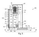
- Fig. 5 shows a longitudinal section through a friction clutch 300 according to a second embodiment.
- the friction clutch 300 is substantially identical to that in FIGS FIGS. 1 to 4 shown friction clutch 10 is formed.
- the coupling device 135 has a piston 305.
- the piston 305 delimits a pressure space 310 of the coupling device 135.
- a friction surface 315 is provided in the coupling device 135, which is arranged on a shoulder 316 of the hub 81 on a side facing the carrier plate 125.
- the carrier disk 125 is arranged between the piston 305 of the coupling device 135 and the friction surface 315.
- the pressure chamber 310 of the coupling device 135 is fluidically connected via a connecting channel 320 to the pressure chamber 105 of the compression device 100. Both the pressure chamber 310 of the coupling device 135 and the pressure chamber 105 of the compression device 100 are filled with the pressure oil 110.
- the friction clutch 300 is actuated and the pressure oil 110 in the pressure chamber 105 of the compression device 100 pressurized oil 110, not only the piston 115 of the compression device 100, but also the piston 305 of the coupling device 135 is axially displaced in the direction of the Abbrems gifted 15.
- the piston 305 of the coupling device 135 presses the carrier disk 125 by way of example against the friction surface 315.
- the carrier disk 125 is connected in a torque-locking manner to the output side 40.
- the coupling device 135 disengages when the pressure oil 110 is no longer pressurized.
- the carrier plate 125 and the Abbrems recognized 15 again free according to the circulation of the cooling liquid 30 in the wet space 25 to rotate about the rotation axis 45.
- a control valve 325 may be provided in the connection channel 320, which opens or closes the connection channel 320.
- the control valve 325 may, for example, with the in Fig. 1 be shown connected control device and operated by this.
- control valve 325 may be formed, for example, as a temperature-sensitive valve that opens the connection channel 320 when a predefined threshold value of a temperature of the cooling liquid 30 is exceeded and thus allows a transfer of the pressure oil 110 from the pressure chamber 105 of the compression device 100 into the pressure chamber 310 of the coupling device 135 , Upon cooling of the temperature of the cooling liquid 30, the temperature-sensitive control valve 325 closes the connecting channel 320 and thus separates the pressure chamber 105 of the compression device 100 from the pressure chamber 310 of the coupling device 135. As a result, upon actuation of the compression device 100, the coupling device 135 is not actuated and thus the switching state of Coupling device 135 is not changed at a too low temperature of the cooling liquid 30.
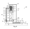
- Fig. 6 shows a longitudinal section through a friction clutch 400 according to a third embodiment.
- the friction clutch 400 substantially corresponds to that in the Fig. 1 to 5
- a web 405 is provided on the piston 115 of the compression device 100, which mechanically couples the coupling device 135 to the compression device 100. If the piston 115 by the pressurization of the pressure oil 110 in Fig. 1 shifted to the right, the coupling device 135 is also actuated via the web 405 or the support plate 125 is pressed against the friction surface 315 of the coupling device 135, so that the switching state of the coupling device 135 is changed and the coupling device 135 is closed. In this way, a simple mechanical coupling over the travel of the piston 115 for actuating the coupling device 135 by means of the compression device 100 can be provided.
- the embodiments of the coupling device 135 are exemplary. Of course, the coupling device 135 may be formed differently and / or the features shown above are combined. It is also conceivable that the control of the coupling device 135 is adapted accordingly. It is particularly conceivable that additional operating points at which, for example, the coupling device 135 is in a grinding state, can also be controlled. Also, the combination of the switching states of the coupling device 135 to the engaged or disengaged state of the friction clutch 10 is arbitrary.
- the clutch device 135 is switched such that upon engagement of the friction clutch 10, in which the largest frictional heat is generated, the circulation of the cooling liquid 30 is strongest and thus the rotational speed of the Abbrems worn 15 is the lowest.
- the circulation of the cooling liquid 30 is strongest when the support disk 125 is connected to the braking device 15.
- the coupling device 135 has a freewheel to allow a low-friction co-rotation of the Abbrems worn 15 on the support plate 125 in the circulation of the cooling liquid 30 and so to keep the efficiency of the friction clutch 10 is particularly high.
- the embodiment of the braking device 15 shown in the embodiment is exemplary.
- the brake structure 130 of the Abbrems worn 15 is designed differently.
- the blade 145 for example bulges in the carrier disk 125 are provided as the brake structure 130.
- the configuration of the blades 145 of the brake structure 130 is different.
- a particularly good cooling of the disk pack 60 is provided when the friction clutch 10, 300, 400 radially additionally cooled coolant 30 is provided via a flow 410 coming from a cooler or the hydrodynamic converter in the friction clutch 10, 300, 400. Thereby, the temperature of the cooling liquid 30 and the plate pack 60 can be further reduced.
- a return 415 which likewise takes place radially on the inside in the region of the hub 81, heated cooling liquid 30 can be conveyed out of the friction clutch 10, 300, 400 and, for example, forwarded to an oil cooler for cooling.
- the abovementioned friction clutches 10, 300, 400 are particularly suitable as friction clutches for bridging a converter transmission.
- the friction clutches 10, 300, 400 are also designed as wet double clutches, wet starting clutches or wet power shift clutches.
- the cooling liquid 30 is provided in order to cool the friction clutches 10, 300, 400.
- the friction clutches 10, 300, 400 are designed as a three-channel coupling, that is to say comprising two channels for the inflow and outflow of the cooling liquid 30 and a separate channel for controlling the compression device 100.
- control device 185 it is also conceivable for the control device 185 to control the coupling device 135 instead of the temperature of the cooling liquid 30 as a function of a temperature of the friction disks 50, 55 and / or as a function of a travel path of the piston 115 of the compression device 100.
- a particularly high cooling of the friction plates is provided independently of the speed difference between the input side and output side. This is particularly advantageous, since even after several high-energy coupling processes a strong cooling can be provided by the cooling liquid. Also, an improved cooling of the disk pack 60 can be provided at low speed differences between the input side 35 and the output side 40, by a (switchable) increase in the speed difference between the braking device 60 and the cooling liquid 30.
Landscapes
- Engineering & Computer Science (AREA)
- General Engineering & Computer Science (AREA)
- Mechanical Engineering (AREA)
- Mechanical Operated Clutches (AREA)
- Hydraulic Clutches, Magnetic Clutches, Fluid Clutches, And Fluid Joints (AREA)
Abstract
Description
- Die Erfindung betrifft eine Reibkupplung umfassend eine Eingangsseite und eine Ausgangsseite, die drehbar um eine Drehachse angeordnet sind, sowie einen Nassraum, der mit einer Kühlflüssigkeit befüllbar ist, wobei in dem Nassraum ein erster Reibpartner, der mit der Eingangsseite drehmomentschlüssig verbunden ist, ein zweiter Reibpartner, der mit der Ausgangsseite drehmomentschlüssig verbunden ist, und eine Kompressionseinrichtung, die ausgebildet ist, eine axiale Kompression des ersten Reibpartners und des zweiten Reibpartners zur Erzeugung eines Drehmomentschlusses zwischen der Eingangsseite und der Ausgangsseite bereitzustellen, angeordnet sind.
- Aus der
DE 10 2012 208 579 A1 ist eine Drehmomentübertragungseinrichtung in einem Antriebsstrang eines Kraftfahrzeugs mit einer um eine Drehachse drehbaren und in einem Gehäuse aufgenommenen Kupplungseinrichtung mit einem Reibbereich zur reibschlüssigen Verbindung einer Antriebsseite mit einer Abtriebsseite und einer zur Zuführung von Fluid in das Gehäuse vorgesehenen ersten Durchlassöffnung und einer zum Abfluss von Fluid aus dem Gehäuse vorgesehenen zweiten Durchlassöffnung und einem die erste und zweite Öffnung passierenden und den Reibbereich durchströmenden ersten Kühlfluidstrom zur Kühlung des Reibbereichs bekannt, wobei der Reibbereich von einem zweiten Kühlfluidstrom durchströmt wird, der in dem Gehäuse zirkuliert, vorrangig unter Umgehung eines Durchtritts durch die erste und zweite Durchlassöffnung. - Es ist Aufgabe der Erfindung, eine verbesserte Reibkupplung bereitzustellen, die eine verbesserte Kühlung aufweist.
- Diese Aufgabe wird mittels einer Reibkupplung gemäß Patentanspruch 1 gelöst. Vorteilhafte Ausführungsformen sind in den abhängigen Ansprüchen angegeben.
- Erfindungsgemäß wurde erkannt, dass eine verbesserte Reibkupplung dadurch bereitgestellt werden kann, dass die Reibkupplung eine Eingangsseite und eine Ausgangsseite umfasst, die drehbar um eine Drehachse angeordnet sind. Ferner umfasst die Reibkupplung einen Nassraum, der mit einer Kühlflüssigkeit befüllbar ist. In dem Nassraum ist ein erster Reibpartner, der drehmomentschlüssig mit der Eingangsseite verbunden ist, und ein zweiter Reibpartner, der drehmomentschlüssig mit der Ausgangsseite verbunden ist, sowie eine Kompressionseinrichtung angeordnet, die ausgebildet ist, eine axiale Kompression des ersten Reibpartners und des zweiten Reibpartners zur Erzeugung eines Drehmomentschlusses zwischen der Eingangsseite und der Ausgangsseite bereitzustellen. Ferner ist in dem Nassraum eine Abbremseinrichtung für die Kühlflüssigkeit vorgesehen, die axial angrenzend an den ersten und/oder den zweiten Reibpartner angeordnet ist. Die Abbremseinrichtung ist ausgebildet, eine Umfangsgeschwindigkeit der Kühlflüssigkeit zu reduzieren.
- Auf diese Weise wird gewährleistet, dass die Kühlflüssigkeit nach dem Austritt zwischen dem ersten und dem zweiten Reibpartner zügig in Umfangsgeschwindigkeit abgebremst wird und somit die Rückführung der Kühlflüssigkeit von radial außen nach radial innen gewährleistet wird. Dadurch kann eine Zirkulation der Kühlflüssigkeit innerhalb der Reibkupplung erhöht werden und somit eine beim Anfahren in die Reibkupplung eingebrachte Reibwärme zuverlässig aus den Reibpartnern abgeführt werden, um so zuverlässig eine Überhitzung der Reibpartner zu vermeiden. Ferner wird auch einem übermäßigen Verschleiß der Kühlflüssigkeit vorgebeugt. Dadurch kann insgesamt die Lebensdauer der Reibkupplung erhöht werden.
- In einer weiteren Ausführungsform umfasst die Abbremseinrichtung eine Trägerscheibe. An der Trägerscheibe ist eine Bremsstruktur vorgesehen. Die Bremsstruktur ist dabei an einer dem ersten und/oder zweiten Reibpartner zugewandten Stirnseite der Trägerscheibe angeordnet. Auf diese Weise wird eine besonders in axialer Richtung kompakte Abbremseinrichtung bereitgestellt, so dass insgesamt die Reibkupplung einen geringen axialen Bauraum benötigt.
- In einer weiteren Ausführungsform umfasst die Bremsstruktur wenigstens eine Schaufel. Die Schaufel ist dabei insbesondere schräg oder senkrecht zu einer Tangente an die Trägerscheibe angeordnet, so dass die Schaufel die Kühlflüssigkeit radial nach innen fördert. Dadurch kann besonders stark die Umfangsgeschwindigkeit der zwischen den Reibpartnern austretenden Kühlflüssigkeit reduziert werden und insbesondere, wenn die Schaufel schräg zu der Tangente an die Trägerscheibe angeordnet ist, die Kühlflüssigkeit mittels der Umfangsgeschwindigkeit besonders gut radial nach innen gefördert werden. Dadurch kann die Zirkulation der Kühlflüssigkeit innerhalb der Reibkupplung weiter erhöht werden.
- In einer weiteren Ausführungsform ist eine Kupplungseinrichtung vorgesehen, wobei die Kupplungseinrichtung wenigstens einen ersten und einen zweiten Schaltzustand umfasst. In dem ersten Schaltzustand verbindet die Kupplungseinrichtung die Abbremseinrichtung drehmomentschlüssig mit einer weiteren Komponente der Reibkupplung. In einem zweiten Schaltzustand rückt die Kupplungseinrichtung aus, um eine Drehmomentübertragung zwischen der Abbremseinrichtung und der weiteren Komponente zumindest teilweise zu unterbrechen. Auf diese Weise kann die Abbremseinrichtung gesteuert werden. Dadurch kann die Zirkulation der Kühlflüssigkeit je nach Betriebszustand der Reibkupplung und entsprechend der Belastung der Reibpartner gesteuert werden, so dass neben einem Betriebszustand mit hoher Zirkulation der Kühlflüssigkeit auch ein Betriebszustand mit geringer Zirkulation, bei der die Abbremseinrichtung z. B. frei im Strom der Kühlflüssigkeit mitläuft, bereitgestellt werden kann. Dadurch kann zum einen die Temperatur der Reibpartner gering gehalten werden und zum anderen der Wirkungsgrad der Reibkupplung erhöht werden.
- In einer weiteren Ausführungsform ist die weitere Komponente die Ausgangsseite der Reibkupplung oder eine drehfeste Komponente eines Antriebsstrangs, insbesondere ein Leitradstutzen eines hydrodynamischen Wandlers. Dadurch kann eine besonders hohe Drehzahldifferenz zwischen der in Umfangsrichtung rotierenden Kühlflüssigkeit und der Abbremseinrichtung bereitgestellt werden, wodurch besonders effizient die Zirkulation der Kühlflüssigkeit innerhalb der Reibkupplung erhöht wird.
- In einer weiteren Ausführungsform ist eine Steuereinrichtung vorgesehen, die ausgebildet ist, die Kupplungseinrichtung zur Schaltung der wenigstens zwei Schaltzustände anzusteuern.
- Besonders vorteilhaft ist, wenn die Steuereinrichtung ausgebildet ist, eine Temperatur der Kühlflüssigkeit und/oder wenigstens eines Reibpartners und/oder einen Verfahrweg der Kompressionseinrichtung zu erfassen, wobei bei einem Überschreiten oder Unterschreiten eines vordefinierten Schwellenwerts der erfassten Temperatur der Kühlflüssigkeit und/oder des wenigstens einen Reibpartners und/oder des Verfahrwegs, die Steuereinrichtung die Kupplungseinrichtung zum Wechsel des Schaltzustands der Kupplungseinrichtung ansteuert. Dadurch kann das Betriebsverhalten der Reibkupplung, insbesondere der Zirkulation der Kühlflüssigkeit innerhalb der Reibkupplung auf einfache Weise an den jeweiligen Betriebszustand der Reibkupplung angepasst werden.
- In einer weiteren Ausführungsform umfasst die Steuereinrichtung eine Zeitmesseinrichtung, wobei die Zeitmesseinrichtung ausgebildet ist, bei Überschreiten des Schwellenwerts eine Zeiterfassung zu starten und wobei die Steuereinrichtung ausgebildet ist, bei Ablauf eines durch die Zeitmesseinrichtung erfassten vordefinierten Zeitintervalls die Kupplungseinrichtung zum Wechsel des Schaltzustands der Kupplungseinrichtung anzusteuern. Auf diese Weise wird gewährleistet, dass die Reibkupplung, nachdem bei dem Überschreiten des Schwellenwerts die Kupplungseinrichtung vom ersten Schaltzustand in den zweiten Schaltzustand wechselte, nach Ablauf des vordefinierten Zeitintervalls wieder in den ersten Schaltzustand zurückwechselt und somit die Reibkupplung ein einheitliches Betriebsverhalten aufweist.
- In einer weiteren Ausführungsform weist die Kompressionseinrichtung einen ersten Druckkolben und einen vom ersten Druckkolben begrenzten ersten Druckraum auf. Die Kupplungseinrichtung weist einen zweiten Druckkolben auf, der einen zweiten Druckraum begrenzt. Der erste und der zweite Druckraum sind mit einem Drucköl befüllbar. Der zweite Druckkolben ist ausgebildet, mittels des Drucköls verschoben zu werden, um einen Drehmomentschluss zwischen der Abbremseinrichtung und der weiteren Komponente bereitzustellen. Der erste und der zweite Druckraum sind fluidisch über einen Verbindungskanal verbunden. Insbesondere ist in dem Verbindungskanal ein Steuerventil der Steuereinrichtung angeordnet, das ausgebildet ist, den Verbindungskanal zu öffnen und zu schließen, wobei insbesondere das Steuerventil als temperatursensitives Ventil ausgebildet ist. Auf diese Weise wird gewährleistet, dass durch die fluidische Verbindung über den Verbindungskanal die Kupplungseinrichtung synchron mit der Kompressionseinrichtung gesteuert wird. So kann beispielsweise im ersten Schaltzustand die Kupplungseinrichtung drehmomentschlüssig mit der Ausgangsseite verbunden sein. Die Kompressionseinrichtung stellt den Drehmomentschluss zwischen der Eingangs- und Ausgangsseite bei Druckbeaufschlagung mit dem Drucköl bereit. Gleichzeitig wird dabei die Kupplungseinrichtung ausgerückt, so dass die Abbremseinrichtung sich frei mit der Kühlflüssigkeit drehen kann. Dadurch wird während des Einkuppelns die Kühlflüssigkeit durch die Abbremseinrichtung abgebremst und gleichzeitig eine hohe Zirkulation bereitgestellt, während hingegen im eingekuppelten Zustand der Reibkupplung der Wirkungsgrad der Reibkupplung durch eine Reduktion der Zirkulation, da die Abbremseinrichtung ausgekuppelt ist, erhöht ist.
- In einer weiteren Ausführungsform umfasst die Kompressionseinrichtung einen Kolben und einen Druckraum, der durch den Kolben begrenzt wird. Der Druckraum ist mit einem Drucköl befüllbar, um den Kolben axial zu verschieben und die Reibpartner axial zu komprimieren, wobei der Kolben stirnseitig auf einer dem Druckraum abgewandten Stirnseite ein Verbindungselement aufweist, das die Kupplungseinrichtung mit dem Kolben koppelt, wobei bei einer axialen Verschiebung des Kolbens der Kompressionseinrichtung die Kupplungseinrichtung betätigt wird. Auf diese Weise kann eine einfache mechanische Kopplung zwischen der Kompressionseinrichtung und der Kupplungseinrichtung bereitgestellt werden, um die Kupplungseinrichtung über die Kompressionseinrichtung anzusteuern.
- Nachfolgend wird die Erfindung anhand von Figuren näher erläutert. Dabei zeigen:
- Fig. 1
- einen Längsschnitt durch eine Reibkupplung gemäß einer ersten Ausführungsform mit einer Abbremseinrichtung;
- Fig. 2
- eine Draufsicht auf die in
Fig. 1 gezeigte Abbremseinrichtung; - Fig. 3
- einen Längsschnitt durch die in
Fig. 2 gezeigte Abbremseinrichtung; - Fig. 4
- einen Querschnitt durch die in
Fig. 3 gezeigte Abbremseinrichtung entlang einer inFig. 3 gezeigten Schnittebene B-B; - Fig. 5
- eine Reibkupplung gemäß einer zweiten Ausführungsform; und
- Fig. 6
- eine Reibkupplung gemäß einer dritten Ausführungsform.
-
Fig. 1 zeigt einen Längsschnitt durch eine Reibkupplung 10 mit einer Abbremseinrichtung 15.Fig. 2 zeigt eine Draufsicht auf die inFig. 1 gezeigte Abbremseinrichtung 15 undFig. 3 zeigt einen Längsschnitt durch die inFig. 2 gezeigte Abbremseinrichtung 15.Fig. 4 zeigt einen Querschnitt durch die inFig. 3 gezeigte Abbremseinrichtung entlang einer inFig. 3 gezeigten Schnittlinie B-B. Nachfolgend sollen dieFign. 1 bis 4 zusammen erläutert werden, wobei gleiche Bauteile mit gleichen Bezugszeichen bezeichnet werden. - Die Reibkupplung 10 umfasst ein Kupplungsgehäuse 20. Das Kupplungsgehäuse 20 begrenzt innenseitig einen Nassraum 25, in dem eine Kühlflüssigkeit 30, vorzugsweise ein Kühlöl, vorgesehen ist. In der Ausführungsform ist der Nassraum 25 vollständig mit der Kühlflüssigkeit 30 geflutet. Selbstverständlich ist auch denkbar, dass der Nassraum 25 nur teilweise mit Kühlflüssigkeit 30 geflutet ist.
- Die Reibkupplung 10 umfasst eine Eingangsseite 35 und eine Ausgangsseite 40. Dabei kann die Eingangsseite 35 beispielsweise mit einem Antriebsmotor, insbesondere einem Verbrennungsmotor eines Kraftfahrzeugs, drehmomentschlüssig verbunden werden. An der Ausgangsseite 40 kann beispielsweise ein Getriebe eines Kraftfahrzeugs angeordnet werden. Die Reibkupplung 10 ist drehbar um eine Drehachse 45.
- In dem Nassraum 25 sind ferner erste Reiblamellen 50 abwechselnd mit zweiten Reiblamellen 55 in einem Lamellenpaket 60 axial angrenzend zueinander angeordnet. Die ersten Reiblamellen 50 weisen dabei eine Innenverzahnung 65 auf. Die zweiten Reiblamellen 55 weisen eine Außenverzahnung 70 auf. Ferner ist in dem Nassraum 25 ein Außenlamellenträger 75 und ein Innenlamellenträger 80 vorgesehen. Der Außenlamellenträger 75 ist dabei mit dem Kupplungsgehäuse 20 verbunden. Der Innenlamellenträger 80 ist mit einer Nabe 81 verbunden. Die Nabe 81 ist dabei mit der Ausgangsseite 40 verbunden, während das Kupplungsgehäuse 20 als Eingangsseite 35 der Reibkupplung 10 dient.
- Der Außenlamellenträger 75 umfasst eine Innenverzahnung 85 und der Innenlamellenträger 80 umfasst eine Außenverzahnung 90. In die Außenverzahnung 90 des Innenlamellenträgers 80 greift die Innenverzahnung 65 der ersten Reiblamelle 50 ein und verbindet die erste Reiblamelle 50 drehmomentschlüssig mit dem Innenlamellenträger 80. In die Innenverzahnung 85 des Außenlamellenträgers 75 greift die Außenverzahnung 70 der zweiten Reiblamelle 55 ein und verbindet die zweite Reiblamelle 55 drehmomentschlüssig mit dem Außenlamellenträger 75. Durch die jeweiligen Außen- und Innenverzahnungen 65, 70, 85, 90 an den Reiblamellen 50, 55 bzw. dem Innenlamellenträger 80 bzw. dem Außenlamellenträger 75 sind die Reiblamellen 50, 55 in axialer Richtung verschiebbar.
- Um eine radiale Durchströmung des Lamellenpakets 60 mit Kühlflüssigkeit 30 zu ermöglichen, sind in dem Innenlamellenträger 80 und in dem Außenlamellenträger 75 jeweils Öffnungen 95 im Bereich der Verzahnungen 85, 90 vorgesehen, durch die die Kühlflüssigkeit 30 von radial innen nach außen den Innenlamellenträger 80 bzw. den Außenlamellenträger 75 durchströmen kann.
- Ferner ist in dem Nassraum 25 eine Kompressionseinrichtung 100 vorgesehen, die in
Fig. 1 linksseitig axial angrenzend an das Lamellenpaket 60 angeordnet ist. Die Kompressionseinrichtung 100 umfasst einen Druckraum 105, der mit einem Drucköl 110 befüllbar ist. Der Druckraum 105 wird durch das Kupplungsgehäuse 20 und durch einen Kolben 115 begrenzt. Um den Druckraum 105 fluidisch vom Nassraum 25 zu trennen, sind ferner Dichtelemente 120 vorgesehen, die zwischen dem Kupplungsgehäuse 20 und dem Kolben 115 angeordnet sind. Wird der Druckraum 105 mit dem Drucköl 110 befüllt bzw. das Drucköl 110 unter Druck gesetzt, so wird der Kolben 115 in axialer Richtung in Richtung des Lamellenpakets 60 verschoben. Dabei komprimiert der Kolben 115 die Reiblamellen 50, 55 mit einer Druckkraft F, so dass diese in Wirkverbindung zueinander treten. Dadurch entsteht ein Reibschluss zwischen den ersten Reiblamellen 50 und den zweiten Reiblamellen 55, die die Eingangsseite 35 drehmomentschlüssig mit der Ausgangsseite 40 verbinden. Bei dem Reibschluss wird durch die Reibung der Reiblamellen 50, 55 aneinander Wärme in die Reiblamellen 50, 55 eingebracht. - Die stärkste Zirkulation von Kühlflüssigkeit zur Kühlung der Reiblamellen 50, 55 wird bei maximaler Drehzahldifferenz, also wenn die Ausgangsseite 40 steht und die Eingangsseite 35 rotiert, erzeugt. Dabei saugen die mit Eingangsdrehzahl rotierenden ersten Reiblamellen 50 die Kühlflüssigkeit 30 durch die Öffnungen 95 des Innenlamellenträgers 80 radial innenseitig an. Um die Kühlflüssigkeit 30 durch das Lamellenpaket 60 radial nach außen zu fördern bzw. anzusaugen, können die Reiblamellen Nuten in ihren (nicht dargestellten) Reibbelägen aufweisen. Die Kühlflüssigkeit durchströmt das Lamellenpaket 60 radial von innen nach außen hin und tritt radial außenseitig aus dem Lamellenpaket 60 aus. Die Kühlflüssigkeit 30 nimmt dabei die entstehende Wärme aus dem Lamellenpaket 60 auf. Dadurch kann eine Überhitzung der Reiblamellen 50, 55 vermieden werden. Die Kühlflüssigkeit 30 strömt nach Verlassen des Lamellenpakets 60 radial nach außen durch die Öffnungen 95 des Außenlamellenträgers 75. Das Kupplungsgehäuse 20 lenkt die radial nach außen strömende Kühlflüssigkeit 30 in axialer Richtung um, in
Fig. 1 nach rechts, so dass die Kühlflüssigkeit 30 axial innenseitig am Kupplungsgehäuse 20 in Richtung der Abbremseinrichtung 15 strömt. - Die Abbremseinrichtung 15 für die Kühlflüssigkeit 30 ist direkt angrenzend in axialer Richtung an das Lamellenpaket 60 angeordnet und umfasst eine Trägerscheibe 125 mit einer Bremsstruktur 130. Die Bremsstruktur 130 ist dabei radial außenseitig im Wesentlichen auf radialer Höhe des Lamellenpakets 60 an der Trägerscheibe 125 angeordnet. Die Trägerscheibe 125 ist radial innenseitig über eine Kupplungseinrichtung 135 befestigt. Die Kupplungseinrichtung 135 verbindet dabei die Abbremseinrichtung 15 mit der Ausgangsseite 40 der Reibkupplung 10.
- Die Bremsstruktur 130 (vgl.
Fign. 2 und 3 ) umfasst eine Vielzahl in regelmäßigen Abständen in Umfangsrichtung verteilte Ausnehmungen 140 und an der Ausnehmung 140 angeordnete Schaufeln 145. Die Schaufeln 145 erstrecken sich dabei in axialer Richtung hin zum Lamellenpaket 60. Die Ausnehmungen 140 entstehen dadurch, dass die Schaufeln 145 in einem Stanzbiegeprozess aus der Trägerscheibe 125 ausgestanzt und in axialer Richtung gebogen werden. Die Schaufeln 145 der Abbremseinrichtung 15 dienen dazu, eine Umfangsgeschwindigkeit der Kühlflüssigkeit 30 aufgrund einer Drehzahldifferenz zwischen Kühlflüssigkeit und der Abbremseinrichtung 15 zu reduzieren. Wird die Umfangsgeschwindigkeit der Kühlflüssigkeit 30 reduziert, so wirken auf die Kühlflüssigkeit 30 reduzierte Fliehkräfte, so dass die Kühlflüssigkeit 30 auf einfache Weise radial von außen nach innen entlang einer dem Lamellenpaket 60 zugewandten Stirnseite 150 der Trägerscheibe 125 der Abbremseinrichtung 15 geführt werden kann. Dabei wird die Kühlflüssigkeit 30 durch die radial durch das Lamellenpaket 60 strömende Kühlflüssigkeit radial nach innen gesaugt. - Die Schaufeln 145 sind in der Ausführungsform senkrecht zu einer Tangente 155 der Trägerscheibe 125 ausgerichtet und schließen somit zu der Tangente 155 einen rechten Winkel α ein. Selbstverständlich ist auch denkbar, dass die Schaufeln 145, wie in
Fig. 2 strichliert dargestellt, schräg zu der Tangente 155 unter einem Winkel α' > 90° ausgerichtet sind, so dass die Kühlflüssigkeit 30 aufgrund ihrer Umfangsgeschwindigkeit radial von außen nach innen durch die Schaufeln 145 gefördert wird. Dabei sind die Schaufeln schräg in Richtung der Drehrichtung der Kühlflüssigkeit 30 geneigt. Auf diese Weise kann eine besonders hohe Zirkulation von Kühlflüssigkeit 30 bzw. eine hohe Strömungsgeschwindigkeit von radial außen nach innen an der Abbremseinrichtung 15 bereitgestellt werden. - Dabei weist die Schaufel 145 zu der Tangente 155 einen Winkel α' von vorzugsweise wenigstens 120° auf. Aufgrund der schrägen Anordnung und der geringeren Drehzahl wird die Kühlflüssigkeit 30 aufgrund ihrer eigenen Umfangsgeschwindigkeit gegen die Schaufeln 145 gedrückt und durch die Schaufeln 145 nach radial innen geführt. Die Schaufeln 145 sind dabei derart ausgestaltet, dass die Kühlflüssigkeit 30 vor allem radial nach innen strömt. Eine Durchströmung der Kühlflüssigkeit 30 durch die Ausnehmungen 140 wird durch das Schaufelprofil (vgl.
Fig. 5 ) vermieden. - Dabei umfasst das Schaufelprofil der Schaufel 145 einen halbkreisförmigen Abschnitt 160, der an einem festen Ende der Schaufel 145 angeordnet ist, und einen am freien Ende der Schaufel 145 angeordneten geraden Abschnitt 165. Der halbkreisförmige Abschnitt 160 ist somit an einem festen Ende 170 mit der Trägerscheibe 125 verbunden. Durch den halbkreisförmigen Abschnitt 160 wird der axiale Durchtritt durch die Ausnehmungen 140 vermieden und gleichzeitig ein hoher Strömungswiderstand der in Umfangsrichtung rotierenden Kühlflüssigkeit 30 entgegengestellt. Durch die Geschwindigkeitsreduktion in Umfangsrichtung werden die auf die Kühlflüssigkeit 30 wirkenden Fliehkräfte reduziert. Da die mit der Eingangsseite 35 gekoppelten ersten Reiblamellen 50 die Kühlflüssigkeit 30 radial innenseitig ansaugen, kann die Kühlflüssigkeit 30 entlang der Abbremseinrichtung 15 radial verbessert nach innen nachströmen.
- Nachdem die Kühlflüssigkeit 30 radial von außen nach innen über die Abbremseinrichtung 15 geführt wurde, strömt die Kühlflüssigkeit 30 radial innenliegend in axialer Richtung entlang einem parallel zur Drehachse 45 verlaufenden Abschnitt des Innenlamellenträgers 80. Durch die rotierenden Reiblamellen 50, 55 wird die Kühlflüssigkeit 30 abermals durch die Öffnungen 95 angesaugt, so dass die Kühlflüssigkeit 30 nochmals durch das Lamellenpaket 60 zirkuliert und der Kühlflüssigkeitskreislauf geschlossen ist.
- Die Kupplungseinrichtung 135 umfasst einen ersten Schaltzustand und einen zweiten Schaltzustand. In dem ersten Schaltzustand ist die Kupplungseinrichtung 135 ausgerückt, so dass die Trägerscheibe 125 im Wesentlichen frei drehbar ist und nicht drehmomentschlüssig mit der Ausgangsseite verbunden ist. In dem zweiten Schaltzustand ist die Kupplungseinrichtung 135 geschlossen und die Trägerscheibe 125 drehmomentschlüssig mit der Ausgangsseite 40 verbunden.
- Die Kupplungseinrichtung 135 ist über eine erste Verbindung 180 mit einer Steuereinrichtung 185 verbunden. Die Kupplungseinrichtung 135 ist in der Ausführungsform als elektrische schaltbare Kupplung ausgebildet. Auf diese Weise kann die Steuereinrichtung 185 auf einfache Weise die Kupplungseinrichtung 135 betätigen. Ferner ist in dem Nassraum 25 ein Temperatursensor 190 zur Erfassung der Temperatur der Kühlflüssigkeit 30 vorgesehen, der beispielsweise radial außenseitig zu dem Lamellenpaket 60 angeordnet ist. Der Temperatursensor 190 ist über eine zweite Verbindung 195 mit der Steuereinrichtung 185 verbunden. Der Temperatursensor 190 stellt der Steuereinrichtung 185 ein Temperatursignal in Abhängigkeit der Temperatur der Kühlflüssigkeit bereit. Die Steuereinrichtung 185 umfasst ferner einen Speicher 200, in dem ein vordefinierter Schwellenwert hinterlegt ist. Die Steuereinrichtung 185 erfasst das Temperatursignal des Temperatursensors 190. Die Steuereinrichtung 185 vergleicht das erfasste Temperatursignal mit dem im Speicher 200 hinterlegten vordefinierten Schwellenwert für das Temperatursignal. Überschreitet das Temperatursignal des Temperatursensors 190 den vordefinierten Schwellenwert, so steuert die Steuereinrichtung 185 über die erste Verbindung 180 die Kupplungseinrichtung 135 an, um von dem ersten Schaltzustand der Kupplungseinrichtung 135 in den zweiten Schaltzustand zu wechseln. Die Kupplungseinrichtung 135 kuppelt beispielsweise in den zweiten Schaltzustand ein und verbindet drehmomentschlüssig die Trägerscheibe 125 mit der Ausgangsseite 40. Somit rotiert die Trägerscheibe 125, aber auch die Abbremseinrichtung 15 im zweiten Schaltzustand mit Ausgangsdrehzahl. Dadurch wird eine hohe Drehzahldifferenz zwischen der Kühlflüssigkeit 30 und der Abbremseinrichtung 15 bereitgestellt, so dass diese besonders stark die Kühlflüssigkeit 30 in Umfangsrichtung abbremst und radial nach innen führt. Dadurch wird die Zirkulation der Kühlflüssigkeit 30 im Lamellenpaket 60 erhöht und eine verstärkte Kühlung durch die Kühlflüssigkeit 30 im Lamellenpaket 60 bereitgestellt.
- Im ersten Schaltzustand ist die Kupplungseinrichtung 135 ausgerückt, so dass die Trägerscheibe 125 und die daran angeordnete Abbremseinrichtung 15 frei in dem Nassraum 25 rotieren kann. Die Rotationsgeschwindigkeit der Abbremseinrichtung 15 orientiert sich dabei an der Umfangsgeschwindigkeit der Kühlflüssigkeit 30, so dass die Abbremseinrichtung 15 nur eine geringe Drehzahldifferenz zur Kühlflüssigkeit 30 aufweist, und somit nur eine geringe Zirkulation innerhalb der Reibkupplung 10 zur Kühlung des Lamellenpakets 60 bereitgestellt wird. Dadurch werden die Schleppmomente an der Abbremseinrichtung 15 gering gehalten. Dadurch wird der Wirkungsgrad der Reibkupplung 10 erhöht.
- In der Ausführungsform ist die Kupplungseinrichtung 135 drehmomentschlüssig mit der Ausgangsseite 40 verbunden. Alternativ ist auch denkbar, dass die Kupplungseinrichtung 135 drehmomentschlüssig mit einem Leitradstutzen 205 eines hydrodynamischen Wandlers verbunden ist. Diese Ausführungsform ist in
Fig. 1 strichliert dargestellt. Die Verbindung mit dem Leitradstutzen 205 des hydrodynamischen Wandlers hat den Vorteil, dass der Leitradstutzen 205 standardmäßig beim Anschluss der Reibkupplung 10 an ein Automatikgetriebe vorhanden ist. Der Leitradstutzen 205 ist eine Komponente des Wandlers, die drehfest ist und somit nicht um die Drehachse 45 rotiert. Durch die Verbindung der Kupplungseinrichtung 135 mit dem Leitradstutzen 205 kann die Abbremseinrichtung 15 im zweiten Schaltzustand vollständig abgebremst und stillgelegt werden, so dass somit eine besonders hohe Zirkulation der Kühlflüssigkeit 30 zur Kühlung des Lamellenpakets 60 bereitgestellt werden. Dies trifft für jeden Betriebszustand der Reibkupplung 10 zu, solange der Verbrennungsmotor die Eingangsseite 35 antreibt und die Reibkupplung 10 mit diesem verbunden ist. - Zusätzlich kann die Steuereinrichtung 185 eine Zeiterfassungseinrichtung 210 umfassen. In dem Speicher 200 ist ein vordefiniertes Zeitintervall hinterlegt, wobei der Speicher 200 das vordefinierte Zeitintervall der Zeiterfassungseinrichtung 210 bereitstellt. Die Zeiterfassungseinrichtung 210 ist dabei ausgebildet, ein Ablaufen des vordefinierten Zeitintervalls zu ermitteln.
- Die Zeiterfassungseinrichtung 210 startet eine Zeiterfassung zur Ermittlung des ablaufenden Zeitintervalls, wenn das Temperatursignal den im Speicher 200 abgelegten Schwellenwert für die Temperatur überschreitet und die Steuereinrichtung 185 die Kupplungseinrichtung vom ersten in den zweiten Schaltzustand schaltet. Als besonders vorteilhaft hat sich ein vordefiniertes Zeitintervall von 5 bis 10 Sekunden herausgestellt. Nach Ablauf des vordefinierten Zeitintervalls signalisiert dies die Zeiterfassungseinrichtung 210 der Steuereinrichtung 185, worauf diese die Kupplungseinrichtung 135 zum Wechseln vom zweiten in den ersten Schaltzustand ansteuert. Auf diese Weise wird gewährleistet, dass die Abbremseinrichtung 15 dauerhaft hauptsächlich frei in der Zirkulation der Kühlflüssigkeit 30 mit rotiert und sich die Kupplungseinrichtung 135 im ersten Schaltzustand befindet. Dabei ist die Zirkulation auf thermisch hochbelasteten Betriebszuständen der Reibkupplung 10 reduziert. Auf diese Weise weist die Reibkupplung 10 einen hohen Wirkungsgrad bei gleichzeitig geringer Überhitzungsempfindlichkeit auf.
-
Fig. 5 zeigt einen Längsschnitt durch eine Reibkupplung 300 gemäß einer zweiten Ausführungsform. Die Reibkupplung 300 ist im Wesentlichen identisch zu der in denFign. 1 bis 4 gezeigten Reibkupplung 10 ausgebildet. Abweichend dazu weist die Kupplungseinrichtung 135 einen Kolben 305 auf. Der Kolben 305 begrenzt einen Druckraum 310 der Kupplungseinrichtung 135. Ferner ist eine Reibfläche 315 in der Kupplungseinrichtung 135 vorgesehen, die an einem Absatz 316 der Nabe 81 auf einer der Trägerscheibe 125 zugewandten Seite angeordnet ist. Die Trägerscheibe 125 ist zwischen dem Kolben 305 der Kupplungseinrichtung 135 und der Reibfläche 315 angeordnet. Der Druckraum 310 der Kupplungseinrichtung 135 ist über einen Verbindungskanal 320 mit dem Druckraum 105 der Kompressionseinrichtung 100 fluidisch verbunden. Sowohl der Druckraum 310 der Kupplungseinrichtung 135 als auch der Druckraum 105 der Kompressionseinrichtung 100 sind mit dem Drucköl 110 befüllt. - Wird die Reibkupplung 300 betätigt und das Drucköl 110 im Druckraum 105 der Kompressionseinrichtung 100 mit Drucköl 110 beaufschlagt, so wird nicht nur der Kolben 115 der Kompressionseinrichtung 100, sondern auch der Kolben 305 der Kupplungseinrichtung 135 axial in Richtung der Abbremseinrichtung 15 verschoben. Dabei drückt der Kolben 305 der Kupplungseinrichtung 135 die Trägerscheibe 125 beispielhaft an die Reibfläche 315 an. Dadurch wird die Trägerscheibe 125 drehmomentschlüssig mit der Ausgangsseite 40 verbunden. Die Kupplungseinrichtung 135 rückt aus, wenn das Drucköl 110 nicht mehr mit Druck beaufschlagt wird. Dadurch kann dann die Trägerscheibe 125 bzw. die Abbremseinrichtung 15 wieder frei entsprechend der Zirkulation der Kühlflüssigkeit 30 im Nassraum 25 um die Drehachse 45 rotieren.
- Zusätzlich kann in dem Verbindungskanal 320 ein Steuerventil 325 vorgesehen sein, das den Verbindungskanal 320 öffnet oder schließt. Das Steuerventil 325 kann beispielsweise mit der in
Fig. 1 gezeigten Steuereinrichtung verbunden sein und durch diese betätigt werden. - Alternativ kann das Steuerventil 325 beispielsweise auch als temperatursensitives Ventil ausgebildet sein, das bei Überschreiten eines vordefinierten Schwellenwerts einer Temperatur der Kühlflüssigkeit 30 den Verbindungskanal 320 öffnet und somit einen Übertritt des Drucköls 110 aus dem Druckraum 105 der Kompressionseinrichtung 100 in den Druckraum 310 der Kupplungseinrichtung 135 ermöglicht. Bei einem Abkühlen der Temperatur der Kühlflüssigkeit 30 schließt das temperatursensitive Steuerventil 325 den Verbindungskanal 320 und trennt somit den Druckraum 105 der Kompressionseinrichtung 100 von dem Druckraum 310 der Kupplungseinrichtung 135. Dadurch wird bei Betätigung der Kompressionseinrichtung 100 die Kupplungseinrichtung 135 nicht betätigt und somit der Schaltzustand der Kupplungseinrichtung 135 bei einer zu niedrigen Temperatur der Kühlflüssigkeit 30 nicht gewechselt.
-
Fig. 6 zeigt einen Längsschnitt durch eine Reibkupplung 400 gemäß einer dritten Ausführungsform. Die Reibkupplung 400 entspricht im Wesentlichen den in denFig. 1 bis 5 gezeigten Reibkupplungen 10, 300. Abweichend dazu ist jedoch an dem Kolben 115 der Kompressionseinrichtung 100 ein Steg 405 vorgesehen, der die Kupplungseinrichtung 135 mit der Kompressionseinrichtung 100 mechanisch koppelt. Wird der Kolben 115 durch die Druckbeaufschlagung des Drucköls 110 inFig. 1 nach rechts verschoben, so wird über den Steg 405 die Kupplungseinrichtung 135 ebenso betätigt bzw. die Trägerscheibe 125 an den Reibfläche 315 der Kupplungseinrichtung 135 gepresst, so dass der Schaltzustand der Kupplungseinrichtung 135 gewechselt wird und die Kupplungseinrichtung 135 geschlossen ist. Auf diese Weise kann eine einfache mechanische Kopplung über den Verfahrweg des Kolbens 115 zur Betätigung der Kupplungseinrichtung 135 mittels der Kompressionseinrichtung 100 bereitgestellt werden. - Die oben gezeigten Ausführungsformen haben alle gemeinsam, dass durch die Bereitstellung der Kupplungseinrichtung 135 die Abbremseinrichtung 15 gesteuert werden kann und somit je nach Betriebszustand der Reibkupplung 10 die Zirkulation der Kühlflüssigkeit 30 zur Kühlung des Lamellenpakets 60 auf einfache Weise gesteuert werden kann.
- Die Ausgestaltungen der Kupplungseinrichtung 135 sind beispielhaft. Selbstverständlich kann auch die Kupplungseinrichtung 135 andersartig ausgebildet sein und/oder die oben gezeigten Merkmale miteinander kombiniert werden. Auch ist denkbar, dass die Ansteuerung der Kupplungseinrichtung 135 entsprechend adaptiert wird. Dabei ist besonders denkbar, dass zusätzliche Betriebspunkte, an denen beispielsweise die Kupplungseinrichtung 135 sich in einem schleifenden Zustand befindet, ebenso angesteuert werden können. Auch ist die Kombination der Schaltzustände der Kupplungseinrichtung 135 zu dem eingekuppelten oder ausgekuppelten Zustand der Reibkupplung 10 frei wählbar.
- Besonders vorteilhaft ist, wenn die Kupplungseinrichtung 135 derart geschaltet wird, dass beim Einkuppeln der Reibkupplung 10, bei dem die größte Reibungswärme erzeugt wird, die Zirkulation der Kühlflüssigkeit 30 am stärksten ist und somit die Drehzahl der Abbremseinrichtung 15 am geringsten ist. Die Zirkulation der Kühlflüssigkeit 30 ist am stärksten, wenn die Trägerscheibe 125 mit der Abbremseinrichtung 15 steht.
- Auch ist denkbar, dass die Kupplungseinrichtung 135 einen Freilauf aufweist, um ein reibungsarmes Mit-Rotieren der Abbremseinrichtung 15 an der Trägerscheibe 125 in der Zirkulation der Kühlflüssigkeit 30 zu ermöglichen und so den Wirkungsgrad der Reibkupplung 10 besonders hoch zu halten.
- Die in der Ausführungsform gezeigte Ausgestaltung der Abbremseinrichtung 15 ist beispielhaft. Selbstverständlich ist auch denkbar, dass die Bremsstruktur 130 der Abbremseinrichtung 15 andersartig ausgebildet ist. Beispielsweise ist denkbar, dass anstatt der Schaufel 145 beispielsweise Ausbuchtungen in der Trägerscheibe 125 als Bremsstruktur 130 vorgesehen sind. Ferner kann auch auf die Bremsstruktur 130 verzichtet werden. Auch ist denkbar, dass die Ausgestaltung der Schaufeln 145 der Bremsstruktur 130 andersartig ist.
- Eine besonders gute Kühlung des Lamellenpakets 60 wird bereitgestellt, wenn der Reibkupplung 10, 300, 400 radial innenseitig zusätzlich abgekühlte Kühlflüssigkeit 30 über einen Vorlauf 410 kommend von einem Kühler oder dem hydrodynamischen Wandler in die Reibkupplung 10, 300, 400 bereitgestellt wird. Dadurch kann die Temperatur der Kühlflüssigkeit 30 und des Lamellenpakets 60 weiter reduziert werden. Durch einen Rücklauf 415, der ebenfalls radial innenseitig im Bereich der Nabe 81 erfolgt, kann erwärmte Kühlflüssigkeit 30 aus der Reibkupplung 10, 300, 400 gefördert werden und beispielsweise in einen Ölkühler zur Abkühlung weitergeleitet werden.
- Die oben genannten Reibkupplungen 10, 300, 400 eignen sich insbesondere als Reibkupplungen zur Überbrückung eines Wandlergetriebes. Selbstverständlich ist auch denkbar, dass die Reibkupplungen 10, 300, 400 auch als nasse Doppelkupplungen, nasse Anfahrkupplungen oder nasse Lastschaltkupplungen ausgebildet sind. Wesentlich dabei ist jedoch, dass die Kühlflüssigkeit 30 vorgesehen ist, um die Reibkupplungen 10, 300, 400 abzukühlen. Besonders vorteilhaft ist hierbei, wenn die Reibkupplungen 10, 300, 400 als Dreikanalkupplung, also aufweisend zwei Kanäle zum Ein- und Ausströmen der Kühlflüssigkeit 30 und einen separaten Kanal zur Steuerung der Kompressionseinrichtung 100, ausgebildet sind.
- Auch ist denkbar, dass die Steuereinrichtung 185 die Kupplungseinrichtung 135 anstatt der Temperatur der Kühlflüssigkeit 30 in Abhängigkeit einer Temperatur der Reiblamellen 50, 55 und/oder in Abhängigkeit eines Verfahrwegs des Kolbens 115 der Kompressionseinrichtung 100 steuert.
- Durch die oben beschriebenen Reibkupplungen 10, 300, 400 wird insgesamt eine besonders hohe Kühlung der Reiblamellen unabhängig von der Drehzahldifferenz zwischen Eingangsseite und Ausgangsseite bereitgestellt. Dies ist insbesondere von Vorteil, da auch nach mehreren hochenergetischen Kupplungsvorgängen eine starke Kühlung durch die Kühlflüssigkeit bereitgestellt werden kann. Auch kann eine verbesserte Kühlung des Lamellenpakets 60 bei geringen Drehzahldifferenzen zwischen der Eingangsseite 35 und der Ausgangsseite 40 bereitgestellt werden, durch eine (schaltbare) Erhöhung der Drehzahldifferenz zwischen Abbremseinrichtung 60 und der Kühlflüssigkeit 30.
-
- 10
- Reibkupplung
- 15
- Abbremseinrichtung für die Kühlflüssigkeit
- 20
- Kupplungsgehäuse
- 25
- Nassraum
- 30
- Kühlflüssigkeit
- 35
- Eingangsseite
- 40
- Ausgangsseite
- 45
- Drehachse
- 50
- erste Reiblamelle
- 55
- zweite Reiblamelle
- 60
- Lamellenpacket
- 65
- Innenverzahnung
- 70
- Aussenverzahnung
- 75
- Außenlamellenträger
- 80
- Innenlamellenträger
- 81
- Nabe
- 85
- Innenverzahnung des Außenlamellenträgers
- 90
- Außenverzahnung des Innenlamellenträgers
- 95
- Öffnung
- 100
- Kompressionseinrichtung
- 105
- Druckraum
- 110
- Drucköl
- 115
- Kolben
- 120
- Dichtelement
- 125
- Trägerscheibe
- 130
- Bremsstruktur
- 135
- Kupplungseinrichtung
- 140
- Ausnehmung
- 145
- Schaufel
- 150
- Stirnseite
- 155
- Tangente
- 160
- Halbkreisförmiger Abschnitt
- 165
- Geradliniger Abschnitt
- 170
- Festes Ende
- 180
- Erste Verbindung
- 185
- Steuereinrichtung
- 190
- Temperatursensor
- 195
- Zweite Verbindung
- 200
- Speicher
- 205
- Leitradstutzen
- 210
- Zeiterfassungseinrichtung
- 300
- Reibkupplung
- 305
- Kolben
- 310
- Druckraum
- 315
- Reibfläche
- 325
- Steuerventil
- 320
- Verbindungskanal
- 400
- Reibkupplung
- 405
- Steg
- 410
- Vorlauf
- 415
- Rücklauf
Claims (10)
- Reibkupplung (10; 300; 400) umfassend:- eine Eingangsseite (35) und eine Ausgangsseite (40), die drehbar um eine Drehachse (45) angeordnet sind, sowie- einen Nassraum (25), der mit einer Kühlflüssigkeit (30) befüllbar ist, wobei in dem Nassraum (25)-- ein erster Reibpartner (50), der mit der Eingangsseite (35) drehmomentschlüssig verbunden ist,-- ein zweiter Reibpartner (55), der mit der Ausgangsseite (40) drehmomentschlüssig verbunden ist,-- und eine Kompressionseinrichtung (100), die ausgebildet ist, eine axiale Kompression des ersten Reibpartner (50) und des zweiten Reibpartners (55) zur Erzeugung eines Drehmomentschlusses zwischen der Eingangsseite (35) (15) und der Ausgangsseite (40) (20) bereitzustellen, angeordnet sind, dadurch gekennzeichnet, dass- eine Abbremseinrichtung (15) für die Kühlflüssigkeit (30) in dem Nassraum (25) vorgesehen ist, die axial angrenzend an den ersten und/oder zweiten Reibpartner (50, 55) angeordnet ist,- wobei die Abbremseinrichtung (15) ausgebildet ist, eine Umfangsgeschwindigkeit der Kühlflüssigkeit (30) zu reduzieren.
- Reibkupplung (10; 300; 400) nach Anspruch 1, dadurch gekennzeichnet, dass die Abbremseinrichtung (15) eine Trägerscheibe (125) aufweist, wobei an der Trägerscheibe (125) eine Bremsstruktur (130) vorgesehen ist, wobei die Bremsstruktur (130) an einer dem ersten und/oder zweiten Reibpartner (50, 55) zugewandten Stirnseite (150) der Trägerscheibe (125) angeordnet ist.
- Reibkupplung (10; 300; 400) nach Anspruch 2, wobei die Bremsstruktur (130) wenigstens eine Schaufel (145) umfasst, wobei die Schaufel (145) insbesondere schräg oder senkrecht zu einer Tangente (155) an die Trägerscheibe (125) angeordnet ist, so dass die Schaufel (145) die Kühlflüssigkeit (30) radial nach innen fördert.
- Reibkupplung (10; 300; 400) nach einem der Ansprüche 1 bis 3, dadurch gekennzeichnet, dass eine Kupplungseinrichtung (135) vorgesehen ist, wobei die Kupplungseinrichtung (135) wenigstens einen ersten und einen zweiten Schaltzustand umfasst, wobei in dem ersten Schaltzustand die Kupplungseinrichtung (135) die Abbremseinrichtung (15) drehmomentschlüssig mit einer weiteren Komponente der Reibkupplung (10; 300; 400) verbindet und in einem zweiten Schaltzustand die Kupplungseinrichtung (135) ausrückt, um eine Drehmomentübertragung zwischen der Abbremseinrichtung (15) und der weiteren Komponente (40, 205) zumindest teilweise zu unterbrechen.
- Reibkupplung (10; 300; 400) nach Anspruch 4, dadurch gekennzeichnet, dass die weitere Komponente die Ausgangsseite (40) der Reibkupplung (10; 300; 400) oder eine drehfeste Komponente (205) eines Antriebsstrangs, insbesondere ein Leitradstutzen (205) eines hydrodynamischen Wandlers, ist.
- Reibkupplung (10; 300; 400) nach Anspruch 4 oder 5, dadurch gekennzeichnet, dass eine Steuereinrichtung (185) vorgesehen ist, die ausgebildet ist, die Kupplungseinrichtung (135) zur Schaltung der wenigstens zwei Schaltzustände anzusteuern.
- Reibkupplung (10; 300; 400) nach Anspruch 6, dadurch gekennzeichnet, dass die Steuereinrichtung (185) ausgebildet ist, eine Temperatur der Kühlflüssigkeit (30) und/oder wenigstens eines Reibpartners (50, 55) und/oder einen Verfahrweg der Kompressionseinrichtung (100) zu erfassen, wobei bei Überschreiten oder Unterschreiten eines vordefinierten Schwellenwerts der erfassten Temperatur der Kühlflüssigkeit (30) und/oder des wenigstens einen Reibpartners (50, 55) und/oder des Verfahrwegs, die Steuereinrichtung (185) die Kupplungseinrichtung (135) zum Wechsel des Schaltzustands der Kupplungseinrichtung (135) ansteuert.
- Reibkupplung (10; 300; 400) nach Anspruch 7, dadurch gekennzeichnet, dass die Steuereinrichtung (185) eine Zeiterfassungseinrichtung (210) umfasst, wobei die Zeiterfassungseinrichtung (210) ausgebildet ist, bei Überschreiten des Schwellenwerts eine Zeiterfassung zu starten und wobei die Steuereinrichtung (185) ausgebildet ist, bei Ablauf eines durch die Zeiterfassungseinrichtung (210) erfassten vordefinierten Zeitintervalls die Kupplungseinrichtung (135) zum Wechsel des Schaltzustands der Kupplungseinrichtung (135) anzusteuern.
- Reibkupplung (10; 300; 400) nach einem der Ansprüche 5 bis 8, dadurch gekennzeichnet, dass Kompressionseinrichtung (100) einen ersten Druckkolben (115) und einen vom ersten Druckkolben (115) begrenzten ersten Druckraum (105) aufweist, wobei die Kupplungseinrichtung (135) einen zweiten Druckkolben (305) umfasst, der einen zweiten Druckraum begrenzt, wobei der erste und der zweite Druckraum mit einem Drucköl (110) befüllbar sind, wobei der zweite Druckkolben (305) ausgebildet ist, mittels des Drucköls (110) verschoben zu werden, um einen Drehmomentschluss zwischen der Abbremseinrichtung (15) und der weiteren Komponente (40, 205) bereitzustellen, wobei der erste und der zweite Druckraum (105, 310) fluidisch über einen Verbindungskanal (320) verbunden sind, wobei insbesondere in dem Verbindungskanal (320) ein Steuerventil (325) der Steuereinrichtung (185) angeordnet ist, das ausgebildet ist, den Verbindungskanal (320) zu öffnen oder zu schließen, wobei insbesondere das Steuerventil (325) als temperatursensitives Ventil ausgebildet ist.
- Reibkupplung (10; 300; 400) nach einem der Ansprüche 3 bis 8, dadurch gekennzeichnet, dass die Kompressionseinrichtung (100) einen Druckkolben (115) und einen Druckraum (105) umfasst, der durch den Druckkolben (115) begrenzt wird, wobei der Druckraum (105) mit einem Drucköl (110) befüllbar ist, um den Druckkolben (115) axial zu verschieben und die Reibpartner (50, 55) axial zu komprimieren, wobei der Druckkolben (115) stirnseitig auf einer dem Druckraum (105) abgewandten Stirnseite ein Verbindungselement (405) aufweist, das die Kupplungseinrichtung (135) mit dem Druckkolben (115) koppelt, wobei bei einer axialen Verschiebung des Druckkolbens (115) der Kompressionseinrichtung (100) die Kupplungseinrichtung (135) betätigt wird.
Applications Claiming Priority (1)
| Application Number | Priority Date | Filing Date | Title |
|---|---|---|---|
| DE102013213180 | 2013-07-05 |
Publications (3)
| Publication Number | Publication Date |
|---|---|
| EP2824348A2 true EP2824348A2 (de) | 2015-01-14 |
| EP2824348A3 EP2824348A3 (de) | 2016-03-23 |
| EP2824348B1 EP2824348B1 (de) | 2018-02-14 |
Family
ID=51059336
Family Applications (1)
| Application Number | Title | Priority Date | Filing Date |
|---|---|---|---|
| EP14175420.0A Not-in-force EP2824348B1 (de) | 2013-07-05 | 2014-07-02 | Reibkupplung |
Country Status (2)
| Country | Link |
|---|---|
| EP (1) | EP2824348B1 (de) |
| DE (1) | DE102014212841A1 (de) |
Families Citing this family (1)
| Publication number | Priority date | Publication date | Assignee | Title |
|---|---|---|---|---|
| CN119122943B (zh) * | 2024-07-31 | 2025-10-17 | 东风汽车集团股份有限公司 | 湿式双离合器温度的确定方法和程序产品 |
Citations (1)
| Publication number | Priority date | Publication date | Assignee | Title |
|---|---|---|---|---|
| DE102012208579A1 (de) | 2011-06-21 | 2012-12-27 | Schaeffler Technologies AG & Co. KG | Drehmomentübertragungseinrichtung |
Family Cites Families (9)
| Publication number | Priority date | Publication date | Assignee | Title |
|---|---|---|---|---|
| US3366210A (en) | 1965-08-26 | 1968-01-30 | Mack Trucks | Wet clutch lubricating system |
| US5460255A (en) | 1993-03-25 | 1995-10-24 | Borg-Warner Automotive, Inc. | Universal segmented friction clutch facing |
| DE19925830A1 (de) | 1999-06-07 | 2000-12-14 | Zahnradfabrik Friedrichshafen | Getriebe mit Retarder |
| ATE357612T1 (de) | 2000-07-17 | 2007-04-15 | Zf Sachs Ag | Mehrfach-kupplungseinrichtung |
| DE10125628A1 (de) | 2001-03-02 | 2002-09-12 | Zf Sachs Ag | Kupplungsanordnung |
| EP1703159B1 (de) | 2005-03-16 | 2010-12-15 | Schaeffler Technologies AG & Co. KG | Verfahren zum Kühlen einer flüssigkeitsgekühlten Reibungskupplung sowie flüssigkeitsgekühlte Reibungskupplung |
| DE102009045612A1 (de) | 2009-10-13 | 2011-05-05 | Zf Friedrichshafen Ag | Nasslaufende Kupplungsanordnung, insbesondere Anfahrkupplung, für ein Fahrzeug |
| DE102009045610A1 (de) | 2009-10-13 | 2011-05-05 | Zf Friedrichshafen Ag | Nasslaufende Kupplungsanordnung |
| DE102010053929A1 (de) | 2009-12-21 | 2011-06-22 | Schaeffler Technologies GmbH & Co. KG, 91074 | Nasskupplung |
-
2014
- 2014-07-02 DE DE102014212841.2A patent/DE102014212841A1/de not_active Withdrawn
- 2014-07-02 EP EP14175420.0A patent/EP2824348B1/de not_active Not-in-force
Patent Citations (1)
| Publication number | Priority date | Publication date | Assignee | Title |
|---|---|---|---|---|
| DE102012208579A1 (de) | 2011-06-21 | 2012-12-27 | Schaeffler Technologies AG & Co. KG | Drehmomentübertragungseinrichtung |
Also Published As
| Publication number | Publication date |
|---|---|
| DE102014212841A1 (de) | 2015-01-08 |
| EP2824348A3 (de) | 2016-03-23 |
| EP2824348B1 (de) | 2018-02-14 |
Similar Documents
| Publication | Publication Date | Title |
|---|---|---|
| DE10004189B4 (de) | Mehrfach-Kupplungseinrichtung | |
| EP2038564B1 (de) | Lamellenbremse in einem automatgetriebe mit steuerbarer kühlölversorgung und verfahren zum betreiben derselben | |
| DE69933745T2 (de) | Mehrscheiben-Reibeinrichtung mit steuerbarer Zwangsschmierung | |
| DE19652571B4 (de) | Anfahrkupplung | |
| DE102012024699A1 (de) | Kupplungsanordnung mit einer Doppelkupplungseinrichtung | |
| DE19500814B4 (de) | Reibring sowie Kupplung mit einem solchen Reibring | |
| DE2809847A1 (de) | Kupplungsbaugruppe | |
| DE19917893A1 (de) | Kupplungseinrichtung, insbesondere Anfahrelement, mit einstellbarer Kupplungskühlung für hohe Verlustleistung | |
| DE10230183B4 (de) | Verfahren zur Kühlfluidzuführung für Lamellenkupplungen und -bremsen in Automatgetrieben und Einrichtung zur Kühlfluidzuführung | |
| DE10239288B4 (de) | Drehmomentwandler, der mit einer Wandlersperrkupplung versehen ist und für eine effektive Wärmeabführung angeordnet ist | |
| DE102014014236A1 (de) | Antriebsstrang für ein Kraftfahrzeug und Verfahren zum Betrieb eines solchen Antriebsstrangs | |
| DE2212367A1 (de) | Fluessigkeitsreibungskupplung, insbesondere fuer den luefterantrieb bei brennkraftmaschinen | |
| EP1482195A2 (de) | Kupplungsvorrichtung und Verfahren zum Betreiben einer Lamellenkupplung | |
| EP0519358A1 (de) | Kühlflüssigkeitssteuerung für eine Kupplung | |
| DE10004286A1 (de) | Kupplungseinrichtung mit einer hydrodynamischen Kupplung und zumindest zwei Reibungskupplungen | |
| DE2351148A1 (de) | Lamellenbremse fuer fahrzeuge | |
| DE60104733T2 (de) | Flüssigkeitsreibungskupplung | |
| EP1857698A2 (de) | Kopplungsanordnung | |
| EP1257751B1 (de) | Reibkupplung, insbesondere wandlerüberbrückungskupplung für einen hydrodynamischen drehmomentwandler | |
| DE102009026985A1 (de) | Anordnung und Verfahren zum Kühlen und/oder Schmieren | |
| DE19854867B4 (de) | Drehzahldifferenzabhängige hydraulische Kupplung | |
| DE102011086376B4 (de) | Ölzufuhrvorrichtung für eine Lamellenbremse | |
| DE102011005504A1 (de) | Lamellenschaltelement | |
| EP2824348B1 (de) | Reibkupplung | |
| WO2003036118A1 (de) | Kupplungsanordnung |
Legal Events
| Date | Code | Title | Description |
|---|---|---|---|
| 17P | Request for examination filed |
Effective date: 20140702 |
|
| AK | Designated contracting states |
Kind code of ref document: A2 Designated state(s): AL AT BE BG CH CY CZ DE DK EE ES FI FR GB GR HR HU IE IS IT LI LT LU LV MC MK MT NL NO PL PT RO RS SE SI SK SM TR |
|
| AX | Request for extension of the european patent |
Extension state: BA ME |
|
| PUAI | Public reference made under article 153(3) epc to a published international application that has entered the european phase |
Free format text: ORIGINAL CODE: 0009012 |
|
| RIN1 | Information on inventor provided before grant (corrected) |
Inventor name: KUEHNLE, MICHAEL |
|
| RAP1 | Party data changed (applicant data changed or rights of an application transferred) |
Owner name: SCHAEFFLER TECHNOLOGIES AG & CO. KG |
|
| PUAL | Search report despatched |
Free format text: ORIGINAL CODE: 0009013 |
|
| AK | Designated contracting states |
Kind code of ref document: A3 Designated state(s): AL AT BE BG CH CY CZ DE DK EE ES FI FR GB GR HR HU IE IS IT LI LT LU LV MC MK MT NL NO PL PT RO RS SE SI SK SM TR |
|
| AX | Request for extension of the european patent |
Extension state: BA ME |
|
| RIC1 | Information provided on ipc code assigned before grant |
Ipc: F16D 25/12 20060101ALI20160216BHEP Ipc: F16D 25/0638 20060101AFI20160216BHEP Ipc: F16D 13/72 20060101ALI20160216BHEP Ipc: F16D 13/52 20060101ALI20160216BHEP |
|
| R17P | Request for examination filed (corrected) |
Effective date: 20160923 |
|
| RBV | Designated contracting states (corrected) |
Designated state(s): AL AT BE BG CH CY CZ DE DK EE ES FI FR GB GR HR HU IE IS IT LI LT LU LV MC MK MT NL NO PL PT RO RS SE SI SK SM TR |
|
| GRAP | Despatch of communication of intention to grant a patent |
Free format text: ORIGINAL CODE: EPIDOSNIGR1 |
|
| INTG | Intention to grant announced |
Effective date: 20170921 |
|
| GRAS | Grant fee paid |
Free format text: ORIGINAL CODE: EPIDOSNIGR3 |
|
| GRAA | (expected) grant |
Free format text: ORIGINAL CODE: 0009210 |
|
| AK | Designated contracting states |
Kind code of ref document: B1 Designated state(s): AL AT BE BG CH CY CZ DE DK EE ES FI FR GB GR HR HU IE IS IT LI LT LU LV MC MK MT NL NO PL PT RO RS SE SI SK SM TR |
|
| REG | Reference to a national code |
Ref country code: GB Ref legal event code: FG4D Free format text: NOT ENGLISH |
|
| REG | Reference to a national code |
Ref country code: CH Ref legal event code: EP |
|
| REG | Reference to a national code |
Ref country code: IE Ref legal event code: FG4D Free format text: LANGUAGE OF EP DOCUMENT: GERMAN |
|
| REG | Reference to a national code |
Ref country code: DE Ref legal event code: R096 Ref document number: 502014007230 Country of ref document: DE Ref country code: AT Ref legal event code: REF Ref document number: 970034 Country of ref document: AT Kind code of ref document: T Effective date: 20180315 |
|
| REG | Reference to a national code |
Ref country code: NL Ref legal event code: MP Effective date: 20180214 |
|
| PG25 | Lapsed in a contracting state [announced via postgrant information from national office to epo] |
Ref country code: NL Free format text: LAPSE BECAUSE OF FAILURE TO SUBMIT A TRANSLATION OF THE DESCRIPTION OR TO PAY THE FEE WITHIN THE PRESCRIBED TIME-LIMIT Effective date: 20180214 Ref country code: CY Free format text: LAPSE BECAUSE OF FAILURE TO SUBMIT A TRANSLATION OF THE DESCRIPTION OR TO PAY THE FEE WITHIN THE PRESCRIBED TIME-LIMIT Effective date: 20180214 Ref country code: HR Free format text: LAPSE BECAUSE OF FAILURE TO SUBMIT A TRANSLATION OF THE DESCRIPTION OR TO PAY THE FEE WITHIN THE PRESCRIBED TIME-LIMIT Effective date: 20180214 Ref country code: NO Free format text: LAPSE BECAUSE OF FAILURE TO SUBMIT A TRANSLATION OF THE DESCRIPTION OR TO PAY THE FEE WITHIN THE PRESCRIBED TIME-LIMIT Effective date: 20180514 Ref country code: FI Free format text: LAPSE BECAUSE OF FAILURE TO SUBMIT A TRANSLATION OF THE DESCRIPTION OR TO PAY THE FEE WITHIN THE PRESCRIBED TIME-LIMIT Effective date: 20180214 Ref country code: ES Free format text: LAPSE BECAUSE OF FAILURE TO SUBMIT A TRANSLATION OF THE DESCRIPTION OR TO PAY THE FEE WITHIN THE PRESCRIBED TIME-LIMIT Effective date: 20180214 Ref country code: LT Free format text: LAPSE BECAUSE OF FAILURE TO SUBMIT A TRANSLATION OF THE DESCRIPTION OR TO PAY THE FEE WITHIN THE PRESCRIBED TIME-LIMIT Effective date: 20180214 |
|
| PG25 | Lapsed in a contracting state [announced via postgrant information from national office to epo] |
Ref country code: LV Free format text: LAPSE BECAUSE OF FAILURE TO SUBMIT A TRANSLATION OF THE DESCRIPTION OR TO PAY THE FEE WITHIN THE PRESCRIBED TIME-LIMIT Effective date: 20180214 Ref country code: SE Free format text: LAPSE BECAUSE OF FAILURE TO SUBMIT A TRANSLATION OF THE DESCRIPTION OR TO PAY THE FEE WITHIN THE PRESCRIBED TIME-LIMIT Effective date: 20180214 Ref country code: RS Free format text: LAPSE BECAUSE OF FAILURE TO SUBMIT A TRANSLATION OF THE DESCRIPTION OR TO PAY THE FEE WITHIN THE PRESCRIBED TIME-LIMIT Effective date: 20180214 Ref country code: BG Free format text: LAPSE BECAUSE OF FAILURE TO SUBMIT A TRANSLATION OF THE DESCRIPTION OR TO PAY THE FEE WITHIN THE PRESCRIBED TIME-LIMIT Effective date: 20180514 Ref country code: GR Free format text: LAPSE BECAUSE OF FAILURE TO SUBMIT A TRANSLATION OF THE DESCRIPTION OR TO PAY THE FEE WITHIN THE PRESCRIBED TIME-LIMIT Effective date: 20180515 |
|
| PG25 | Lapsed in a contracting state [announced via postgrant information from national office to epo] |
Ref country code: MT Free format text: LAPSE BECAUSE OF FAILURE TO SUBMIT A TRANSLATION OF THE DESCRIPTION OR TO PAY THE FEE WITHIN THE PRESCRIBED TIME-LIMIT Effective date: 20180214 |
|
| PG25 | Lapsed in a contracting state [announced via postgrant information from national office to epo] |
Ref country code: AL Free format text: LAPSE BECAUSE OF FAILURE TO SUBMIT A TRANSLATION OF THE DESCRIPTION OR TO PAY THE FEE WITHIN THE PRESCRIBED TIME-LIMIT Effective date: 20180214 Ref country code: IT Free format text: LAPSE BECAUSE OF FAILURE TO SUBMIT A TRANSLATION OF THE DESCRIPTION OR TO PAY THE FEE WITHIN THE PRESCRIBED TIME-LIMIT Effective date: 20180214 Ref country code: RO Free format text: LAPSE BECAUSE OF FAILURE TO SUBMIT A TRANSLATION OF THE DESCRIPTION OR TO PAY THE FEE WITHIN THE PRESCRIBED TIME-LIMIT Effective date: 20180214 Ref country code: EE Free format text: LAPSE BECAUSE OF FAILURE TO SUBMIT A TRANSLATION OF THE DESCRIPTION OR TO PAY THE FEE WITHIN THE PRESCRIBED TIME-LIMIT Effective date: 20180214 Ref country code: PL Free format text: LAPSE BECAUSE OF FAILURE TO SUBMIT A TRANSLATION OF THE DESCRIPTION OR TO PAY THE FEE WITHIN THE PRESCRIBED TIME-LIMIT Effective date: 20180214 |
|
| REG | Reference to a national code |
Ref country code: DE Ref legal event code: R026 Ref document number: 502014007230 Country of ref document: DE |
|
| PLBI | Opposition filed |
Free format text: ORIGINAL CODE: 0009260 |
|
| PLAX | Notice of opposition and request to file observation + time limit sent |
Free format text: ORIGINAL CODE: EPIDOSNOBS2 |
|
| PG25 | Lapsed in a contracting state [announced via postgrant information from national office to epo] |
Ref country code: SM Free format text: LAPSE BECAUSE OF FAILURE TO SUBMIT A TRANSLATION OF THE DESCRIPTION OR TO PAY THE FEE WITHIN THE PRESCRIBED TIME-LIMIT Effective date: 20180214 Ref country code: SK Free format text: LAPSE BECAUSE OF FAILURE TO SUBMIT A TRANSLATION OF THE DESCRIPTION OR TO PAY THE FEE WITHIN THE PRESCRIBED TIME-LIMIT Effective date: 20180214 Ref country code: DK Free format text: LAPSE BECAUSE OF FAILURE TO SUBMIT A TRANSLATION OF THE DESCRIPTION OR TO PAY THE FEE WITHIN THE PRESCRIBED TIME-LIMIT Effective date: 20180214 Ref country code: CZ Free format text: LAPSE BECAUSE OF FAILURE TO SUBMIT A TRANSLATION OF THE DESCRIPTION OR TO PAY THE FEE WITHIN THE PRESCRIBED TIME-LIMIT Effective date: 20180214 |
|
| 26 | Opposition filed |
Opponent name: ZF FRIEDRICHSHAFEN AG Effective date: 20181113 |
|
| PG25 | Lapsed in a contracting state [announced via postgrant information from national office to epo] |
Ref country code: SI Free format text: LAPSE BECAUSE OF FAILURE TO SUBMIT A TRANSLATION OF THE DESCRIPTION OR TO PAY THE FEE WITHIN THE PRESCRIBED TIME-LIMIT Effective date: 20180214 |
|
| REG | Reference to a national code |
Ref country code: CH Ref legal event code: PL |
|
| GBPC | Gb: european patent ceased through non-payment of renewal fee |
Effective date: 20180702 |
|
| PG25 | Lapsed in a contracting state [announced via postgrant information from national office to epo] |
Ref country code: MC Free format text: LAPSE BECAUSE OF FAILURE TO SUBMIT A TRANSLATION OF THE DESCRIPTION OR TO PAY THE FEE WITHIN THE PRESCRIBED TIME-LIMIT Effective date: 20180214 Ref country code: LU Free format text: LAPSE BECAUSE OF NON-PAYMENT OF DUE FEES Effective date: 20180702 |
|
| REG | Reference to a national code |
Ref country code: BE Ref legal event code: MM Effective date: 20180731 |
|
| PLBB | Reply of patent proprietor to notice(s) of opposition received |
Free format text: ORIGINAL CODE: EPIDOSNOBS3 |
|
| REG | Reference to a national code |
Ref country code: IE Ref legal event code: MM4A |
|
| PG25 | Lapsed in a contracting state [announced via postgrant information from national office to epo] |
Ref country code: LI Free format text: LAPSE BECAUSE OF NON-PAYMENT OF DUE FEES Effective date: 20180731 Ref country code: GB Free format text: LAPSE BECAUSE OF NON-PAYMENT OF DUE FEES Effective date: 20180702 Ref country code: FR Free format text: LAPSE BECAUSE OF NON-PAYMENT OF DUE FEES Effective date: 20180731 Ref country code: CH Free format text: LAPSE BECAUSE OF NON-PAYMENT OF DUE FEES Effective date: 20180731 Ref country code: IE Free format text: LAPSE BECAUSE OF NON-PAYMENT OF DUE FEES Effective date: 20180702 |
|
| PG25 | Lapsed in a contracting state [announced via postgrant information from national office to epo] |
Ref country code: BE Free format text: LAPSE BECAUSE OF NON-PAYMENT OF DUE FEES Effective date: 20180731 |
|
| PG25 | Lapsed in a contracting state [announced via postgrant information from national office to epo] |
Ref country code: TR Free format text: LAPSE BECAUSE OF FAILURE TO SUBMIT A TRANSLATION OF THE DESCRIPTION OR TO PAY THE FEE WITHIN THE PRESCRIBED TIME-LIMIT Effective date: 20180214 |
|
| PG25 | Lapsed in a contracting state [announced via postgrant information from national office to epo] |
Ref country code: HU Free format text: LAPSE BECAUSE OF FAILURE TO SUBMIT A TRANSLATION OF THE DESCRIPTION OR TO PAY THE FEE WITHIN THE PRESCRIBED TIME-LIMIT; INVALID AB INITIO Effective date: 20140702 Ref country code: PT Free format text: LAPSE BECAUSE OF FAILURE TO SUBMIT A TRANSLATION OF THE DESCRIPTION OR TO PAY THE FEE WITHIN THE PRESCRIBED TIME-LIMIT Effective date: 20180214 |
|
| REG | Reference to a national code |
Ref country code: DE Ref legal event code: R100 Ref document number: 502014007230 Country of ref document: DE |
|
| PG25 | Lapsed in a contracting state [announced via postgrant information from national office to epo] |
Ref country code: MK Free format text: LAPSE BECAUSE OF NON-PAYMENT OF DUE FEES Effective date: 20180214 |
|
| PLCK | Communication despatched that opposition was rejected |
Free format text: ORIGINAL CODE: EPIDOSNREJ1 |
|
| PG25 | Lapsed in a contracting state [announced via postgrant information from national office to epo] |
Ref country code: IS Free format text: LAPSE BECAUSE OF FAILURE TO SUBMIT A TRANSLATION OF THE DESCRIPTION OR TO PAY THE FEE WITHIN THE PRESCRIBED TIME-LIMIT Effective date: 20180614 |
|
| REG | Reference to a national code |
Ref country code: AT Ref legal event code: MM01 Ref document number: 970034 Country of ref document: AT Kind code of ref document: T Effective date: 20190702 |
|
| PLBN | Opposition rejected |
Free format text: ORIGINAL CODE: 0009273 |
|
| STAA | Information on the status of an ep patent application or granted ep patent |
Free format text: STATUS: OPPOSITION REJECTED |
|
| PG25 | Lapsed in a contracting state [announced via postgrant information from national office to epo] |
Ref country code: AT Free format text: LAPSE BECAUSE OF NON-PAYMENT OF DUE FEES Effective date: 20190702 |
|
| 27O | Opposition rejected |
Effective date: 20200617 |
|
| P01 | Opt-out of the competence of the unified patent court (upc) registered |
Effective date: 20230522 |
|
| PGFP | Annual fee paid to national office [announced via postgrant information from national office to epo] |
Ref country code: DE Payment date: 20240918 Year of fee payment: 11 |
|
| REG | Reference to a national code |
Ref country code: DE Ref legal event code: R119 Ref document number: 502014007230 Country of ref document: DE |
|
| PG25 | Lapsed in a contracting state [announced via postgrant information from national office to epo] |
Ref country code: DE Free format text: LAPSE BECAUSE OF NON-PAYMENT OF DUE FEES Effective date: 20260203 |