EP2823200B2 - Baureihe von getriebegehäusen - Google Patents
Baureihe von getriebegehäusen Download PDFInfo
- Publication number
- EP2823200B2 EP2823200B2 EP13717468.6A EP13717468A EP2823200B2 EP 2823200 B2 EP2823200 B2 EP 2823200B2 EP 13717468 A EP13717468 A EP 13717468A EP 2823200 B2 EP2823200 B2 EP 2823200B2
- Authority
- EP
- European Patent Office
- Prior art keywords
- drive flange
- gear
- gear train
- flange
- series according
- Prior art date
- Legal status (The legal status is an assumption and is not a legal conclusion. Google has not performed a legal analysis and makes no representation as to the accuracy of the status listed.)
- Active
Links
Images


Classifications
-
- F—MECHANICAL ENGINEERING; LIGHTING; HEATING; WEAPONS; BLASTING
- F16—ENGINEERING ELEMENTS AND UNITS; GENERAL MEASURES FOR PRODUCING AND MAINTAINING EFFECTIVE FUNCTIONING OF MACHINES OR INSTALLATIONS; THERMAL INSULATION IN GENERAL
- F16H—GEARING
- F16H57/00—General details of gearing
- F16H57/02—Gearboxes; Mounting gearing therein
- F16H57/033—Series gearboxes, e.g. gearboxes based on the same design being available in different sizes or gearboxes using a combination of several standardised units
-
- F—MECHANICAL ENGINEERING; LIGHTING; HEATING; WEAPONS; BLASTING
- F16—ENGINEERING ELEMENTS AND UNITS; GENERAL MEASURES FOR PRODUCING AND MAINTAINING EFFECTIVE FUNCTIONING OF MACHINES OR INSTALLATIONS; THERMAL INSULATION IN GENERAL
- F16H—GEARING
- F16H57/00—General details of gearing
- F16H57/02—Gearboxes; Mounting gearing therein
- F16H2057/02013—Extension units for gearboxes, e.g. additional units attached to a main gear
-
- F—MECHANICAL ENGINEERING; LIGHTING; HEATING; WEAPONS; BLASTING
- F16—ENGINEERING ELEMENTS AND UNITS; GENERAL MEASURES FOR PRODUCING AND MAINTAINING EFFECTIVE FUNCTIONING OF MACHINES OR INSTALLATIONS; THERMAL INSULATION IN GENERAL
- F16H—GEARING
- F16H57/00—General details of gearing
- F16H57/02—Gearboxes; Mounting gearing therein
- F16H2057/02034—Gearboxes combined or connected with electric machines
-
- F—MECHANICAL ENGINEERING; LIGHTING; HEATING; WEAPONS; BLASTING
- F16—ENGINEERING ELEMENTS AND UNITS; GENERAL MEASURES FOR PRODUCING AND MAINTAINING EFFECTIVE FUNCTIONING OF MACHINES OR INSTALLATIONS; THERMAL INSULATION IN GENERAL
- F16H—GEARING
- F16H57/00—General details of gearing
- F16H57/02—Gearboxes; Mounting gearing therein
- F16H2057/02039—Gearboxes for particular applications
- F16H2057/02069—Gearboxes for particular applications for industrial applications
- F16H2057/02073—Reduction gearboxes for industry
-
- Y—GENERAL TAGGING OF NEW TECHNOLOGICAL DEVELOPMENTS; GENERAL TAGGING OF CROSS-SECTIONAL TECHNOLOGIES SPANNING OVER SEVERAL SECTIONS OF THE IPC; TECHNICAL SUBJECTS COVERED BY FORMER USPC CROSS-REFERENCE ART COLLECTIONS [XRACs] AND DIGESTS
- Y10—TECHNICAL SUBJECTS COVERED BY FORMER USPC
- Y10T—TECHNICAL SUBJECTS COVERED BY FORMER US CLASSIFICATION
- Y10T74/00—Machine element or mechanism
- Y10T74/21—Elements
- Y10T74/2186—Gear casings
Definitions
- the present invention relates to a series of gearbox housings.
- a housing for a transmission that has a plurality of openings.
- the housing is designed to accommodate an input shaft and an output shaft in different relative orientations to one another.
- the input shaft and the output shaft can be provided with gears, bevel gears, and/or worm gears, thus creating a spur gear, a bevel gear, or a worm gear.
- the input and output shafts are each rotatably received in shaft bearings that are connected to the housing.
- bores for attaching a motor are provided on the outside of the housing.
- the genre-forming printed matter DE 1 203 075 B discloses a gearbox housing usable for multiple gearbox types, which, when assembled, is closed on two opposite sides by an end cover.
- a first end cover has a plurality of bearing openings spaced at different distances from one another. This allows for different center distances in the gearbox.
- the second end cover is designed to correspond to the first end cover.
- the end covers are designed to be rotatable relative to the housing. As a result, the shafts and gears in the housing can be positioned differently depending on the desired installation position of the gearbox within the housing.
- the document DE 41 21 299 A1 discloses a gear housing having a mounting opening on one side.
- the housing is designed to accommodate two shafts, on which a worm gear and a worm are mounted, which interact as a worm gear.
- the housing has bearing points designed to accommodate shaft bearings in which the shaft with the worm is rotatably mounted.
- the shaft with the worm is driven via a spur gear stage by a drive shaft that extends through a connecting flange.
- circular bearing openings surrounded by bores are formed on the outside of the housing.
- the object of the present invention is to provide a series of gearbox housings which have an improved interface for attaching a motor, an adapter plate or another gearbox.
- the series of gear housings comprises various sizes. Each size comprises a series of different housing types.
- the housing types are suitable for a spur gear unit and at least one of the following types: bevel gear units, parallel shaft gear units, and worm gear units.
- Each gear housing has a housing opening on the drive side. The housing opening is surrounded by a drive flange for connecting a motor, an adapter plate, or another gear unit.
- the axes of bearing points running perpendicular to the plane of the drive flange which are intended to accommodate shaft bearings for geared parts, lie within a minimum inner diameter of the drive flange when viewed perpendicular to the plane of the drive flange.
- Different sizes differ in their housing dimensions, which are determined in particular by the center distances of the first gear stage, and thus by the power rating.
- the drive flange is a drive-side connection flange designed as a flat surface to which a connection flange of a motor, another gearbox, or an adapter plate is attached.
- a sealant such as a sealing ring, is typically arranged between the two superimposed flanges.
- a plane located within this surface is referred to as the drive flange plane.
- Bearing locations are also called bearing seats.
- Each bearing seat can be assigned an axis that corresponds to the axis of a shaft bearing to be inserted into the bearing seat or of a shaft mounted in the shaft bearing.
- the term "geared parts” refers to all components that mesh or intermeshing with one another and are mounted in a rotating manner, such as spur gears, bevel gears, pinions, and worm gears.
- the invention is based on the finding that a significant benefit and advantage with regard to storage, assembly and maintenance of gear housings and gears based thereon, in particular industrial gears, is achieved if an interior of the gear housing accommodating toothed parts is optimally accessible via the drive interface.
- By maximizing the size of the housing opening it is achieved that the axes of bearing points running perpendicular to the plane of the drive flange, which are intended to accommodate shaft bearings for toothed parts, lie within a minimum inner diameter of the drive flange when viewed perpendicular to the plane of the drive flange. These axes are therefore easily accessible, which serves to facilitate simple and efficient assembly and maintenance, e.g. the adjustability of the bearings.
- the particular advantage is that the axial bearing position of the shafts, which run perpendicular to the plane of the drive flange, within the housing opening allows the bearings for these shafts to be mounted from the motor side, leaving sufficient space for a cover seal.
- the bearing for the bevel pinion shaft can thus also be mounted from the motor side, and the bore for the bevel pinion shaft bearing can be machined from the motor side.
- IEC International Electrotechnical Commission
- NEMA National Electrical Manufacturers Association
- the invention creates a universal motor-gearbox interface at a motor-side housing opening of a gearbox housing.
- the axes of bearing points running perpendicular to the plane of the drive flange, which are provided for receiving shaft bearings for gearing parts lie within the minimum inner diameter of the drive flange when viewed perpendicular to the plane of the drive flange.
- the advantage here is that the assembly and maintenance of shaft bearings, shafts and gearing parts is considerably simplified by the easily accessible location within the housing opening.
- the ratio of a maximum outer diameter of the drive flange to an axial distance of bearing points provided for receiving shaft bearings for gearing parts of a first gear stage is in a range of 2.74 to 3.00 in all sizes.
- the advantage here is that in this value range, the assembly and maintenance of shaft bearings, shafts and gearing parts of a first gear stage is considerably simplified by the easily accessible location within the housing opening.
- the ratio of the minimum outer diameter of the drive flange to the minimum inner diameter of the drive flange is in a range of 1.07 to 1.21 in all sizes.
- the advantage here is that, within this range of values, the opening width of the accessible housing opening is optimized with regard to the given dimensions of the housing, so that the assembly and maintenance of shaft bearings, shafts, and gearing components is significantly simplified due to the easily accessible location within the housing opening.
- holes are arranged in the drive flange, which lie on a bolt circle with a diameter and are intended to receive connecting screws, and wherein, in a design suitable for a spur gear, the ratio of a minimum outer diameter of the drive flange to the bolt circle diameter lies in a range of 0.97 to 1.05 in all sizes.
- the connection circuit with its sealing function is designed to be as space-saving as possible with regard to the given dimensions of the housing, so that the opening width of the accessible housing opening is maximized. In this way, the assembly and maintenance of shaft bearings, shafts and gearing parts is considerably simplified due to the easily accessible location within the housing opening.
- the drive flange is at least substantially circular, i.e., the inner and outer edges of the drive flange each extend at least substantially along an inner and outer circular line, respectively.
- the at least substantially circular flange surface is formed between the inner and outer circular lines.
- the restriction "at least substantially” encompasses the following configurations: the outer edge of the drive flange can have a non-curved section, a so-called flattening, in the 12 o'clock position and/or the 3 o'clock position and/or the 6 o'clock position and/or the 9 o'clock position. It is also possible for the outer edge of the drive flange to have a section with a curvature that differs from the circular part of the outer edge in the 6 o'clock position. Furthermore, the inner edge of the drive flange can have a section with a curvature that differs from the circular part of the inner edge in the 6 o'clock position.
- the drive flange has flattened portions on two opposite sides, the distance between which defines the minimum outer diameter of the drive flange.
- the flattened portions reduce the outer diameter of the connecting flange at the narrowest point of the housing, so that the end flange does not protrude beyond the housing.
- the drive flange has holes arranged point-symmetrically on a bolt circle with a bolt circle diameter and provided for receiving connecting screws.
- the connecting screws connect the drive flange to a corresponding connecting flange of a motor or gearbox.
- the hole circle runs over its entire The circumference of the flange is uninterrupted. This creates a continuous connection surface. This allows the pressure force generated by the connecting bolts to act on a sealing agent, such as a sealing ring, without interruption, thus achieving a reliable seal on the drive flange.
- the substantially circular drive flange has flats on two opposite sides. Eight holes are arranged in the drive flange, with four holes located in each half of the drive flange divided by a straight line separating the flats.
- a "straight line separating the flats" is understood to be a straight line running in the plane of the drive flange that coincides with the shortest connecting line between the opposing flats, i.e., the line connecting the two closest points of the opposing flats.
- the symmetrical hole pattern ensures reliable sealing of the drive flange.
- the holes are arranged outside of and symmetrically to the distance line and a perpendicular transverse line.
- the flange width is reduced at the flattened portions of the drive flange. Drilling a hole at such a narrow point would further reduce the width of a sealant, making reliable sealing impossible. Because the holes are located outside the distance line and the transverse line, i.e., outside the main axes of the drive flange, a sufficient width of a sealant can be ensured at these narrow points.
- the four holes arranged in a flange half are positioned such that a first hole is arranged at a first angle to the distance line, a second hole is arranged at a second angle to the first hole, and a third hole is arranged at a third angle to the second hole, wherein the angles are each measured from a center point of the hole circle, and wherein a ratio of the first to the third angle is constant, preferably 1/2, and a sum of the three angles lies in a range from 112.5 to 118.5.
- This angular position of the holes creates a drive flange with a hole pattern that is uniform for all gearbox housings, thereby increasing interchangeability and simplifying storage.
- a spur gear is designed with a gear housing from a series according to one of claims 1 to 9.
- the series of gear housings according to the invention is particularly well suited for modular gear motors.
- Fig. 1 shows a view of a gearbox housing Gij, which belongs to a series of gearbox housings that includes different sizes of gearbox housings.
- Fig. 2 shows a section of a bevel gear with the Fig. 1 shown gear housing Gij, the section plane being perpendicular to the plane 14 of the drive flange 11.
- the gearbox housing Gij is suitable for the bevel gear type.
- the gearbox housing Gij has a housing opening 10 on the drive side, which is closed by an adapter plate for the attachment of a motor.
- the axes 20 of the bearing points 21, which run perpendicular to the plane 14 of the drive flange 11 and are intended to accommodate shaft bearings, here: the bevel pinion shaft bearings 30, for gearing parts, here: the bevel pinion 31a and the gear 31b of the drive stage meshing with a drive pinion 32, are located in the Fig. 1 shown viewing direction, ie seen perpendicular to the plane 14 of the drive flange 11, within a minimum inner diameter b1 of the drive flange 11.
- the essentially circular drive flange 11 has flattened portions 12 of the outer edge 13a on two opposite sides. Eight holes L are arranged in the drive flange 11, which lie on a bolt circle LK and are provided for receiving connecting screws. Four holes L are arranged in each half 11a and 11b of the drive flange 11, which is divided by a straight line 40 between the flattened portions 12.
- Fig. 3 shows the same view as in Fig. 1 , in which a number of dimensions are additionally specified which are of importance for the invention.
- the figure shows the center distance a1 of the first gear stage.
- Fig. 2 In the bevel gear shown, this center distance a1 corresponds to the distance between the axis 34 of the drive pinion 32 and the axis 20 of the gear 31b meshing therewith.
- the figure also shows the distance q1 between the horizontally opposite flats, i.e., the length of the line connecting the two closest points of the opposite flats 12 on the outer edge 13a of the drive flange 11.
- the distance q1 corresponds to the minimum outer diameter of the drive flange 11, measured along the distance line 40.
- the figure also shows the minimum inner diameter b1 of the drive flange 11. Since the drive flange 11 has a recess 15 on its inner edge 13i in the area of the axis 20, the smallest inner diameter b1 must be measured outside the recess 15, e.g., along the distance line 40.
- the figure shows the bolt circle diameter e1, i.e. the diameter of the circle LK on which the holes L are arranged.
- the figure also shows the maximum outer diameter a2 of the drive flange 11. Since the drive flange 11 has flattened portions 12 on its outer edge 13a in the area of the connecting straight line 40 and the transverse straight line 41 rotated by 90 degrees thereto, the maximum outer diameter a2 must be measured outside the flattened portions 12, e.g. in the diagonal between the distance straight line 40 and the transverse straight line 41.
- Fig. 4 provides a table of the dimensions a1, q1, b1, e1 and a2 (see columns 2 to 6), as well as certain ratios QA, QB and QC of these dimensions (see columns 7 to 9).
- the ratio QA is the ratio of the distance q1 of the horizontally opposite flats q1 to the bolt circle diameter e1.
- the ratio QB is the ratio of the distance q1 of the horizontally opposite flats q1 to the minimum inside diameter b1 of the drive flange 11.
- the ratio QC is the ratio of the maximum outside diameter a2 of the drive flange 11 to the center distance a1 of the first gear stage.
- the specified values are within ranges selected so that the shaft bearings, shafts, and gearing components of the gearboxes are easily accessible through the housing opening. This significantly simplifies assembly and maintenance.
- Fig. 5 shows a schematic view of a drive flange 11 with an indication of angles ⁇ 1, ⁇ 2, and ⁇ 3 of the holes L.
- the holes L located in each half 11a, 11b of the drive flange 11 on the bolt circle LK are arranged in a predetermined angular pattern.
- the vertex of the angles ⁇ 1, ⁇ 2, and ⁇ 3 of the three consecutive holes L is the center point M of the drive flange 11.
- One leg of the first angle ⁇ 1 is the distance line 40, the other leg runs through the axis of the first hole L.
- One leg of the second angle ⁇ 2 runs through the axis of the first hole L, the other leg through the axis of the second hole L.
- One leg of the third angle ⁇ 3 runs through the axis of the second hole L, the other leg through the axis of the third hole L.
- the fourth hole L located in the half 11a of the drive flange 11 is arranged symmetrically to the first hole L.
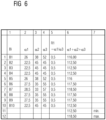
- Fig. 6 provides a table of angles ⁇ 1, ⁇ 2, and ⁇ 3 (see columns 2 to 4), as well as a resulting ratio R1 (see column 5) and the sum of the three angles (see column 6).
- the ratio R1 is the ratio of the first angle ⁇ 1 to the third angle ⁇ 3.
- the dimensions and ratios are listed for twelve different sizes Bi, as specified in column 1. Rows 13 and 14 show the minimum and maximum values of column 6, respectively.
- the eight holes L of the drive flange 11 are arranged point-symmetrically on the drive flange 11 with respect to the center point M of the drive flange 11 and are also arranged symmetrically on the drive flange 11 with respect to the connecting line 40 and the transverse line 41. Therefore, the first angle ⁇ 1 is half the size of the third angle ⁇ 3, i.e., the ratio R1 is constantly 0.5.
- the angles specified are in value ranges selected in such a way that a hole pattern that is congruent for all gearbox housings is created, thereby increasing interchangeability and simplifying storage.
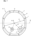
- Fig. 7 to 9 show schematic views of a drive flange 11 for gear housings of different types Tj, but the same size Bi.
- Fig. 7 shows a drive flange 11 of a gearbox housing of type T1 "spur gear".
- the circles drawn around the two lower axes 20 indicate the inner and outer diameters of the bearing location 21.
- the bearing triangle 22 formed by the axes 20 lies thus completely within the housing opening 10.
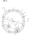
- Fig. 8 shows a drive flange 11 of a gearbox housing of type T2 "parallel gear".
- the circles drawn around the two lower axes 20 indicate the inner and outer diameters of the bearing point 21.
- the bearing triangle 22 formed by the axes 20 thus lies entirely within the housing opening 10.
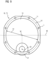
- Fig. 9 shows a drive flange 11 of a gearbox housing of type T3 "bevel gear".
- the two circles drawn around the lower axis 20 indicate the inner and outer diameters of the bearing location 21.
Landscapes
- Engineering & Computer Science (AREA)
- General Engineering & Computer Science (AREA)
- Mechanical Engineering (AREA)
- General Details Of Gearings (AREA)
- Gear Transmission (AREA)
Description
- Die vorliegende Erfindung betrifft eine Baureihe von Getriebegehäusen.
- Für eine kostengünstige Lagerhaltung und Montage ist es wünschenswert, die verschiedenen Getriebe einer Getriebereihe mit einer möglichst universellen Schnittstelle zum Anbau eines Motors, einer Adapterplatte oder eines weiteren Getriebes auszustatten.
- Aus
ES 2 184 570 A1 - Die gattungsbildende Druckschrift
DE 1 203 075 B offenbart ein für mehrere Getriebetypen verwendbares Getriebegehäuse, das im montierten Zustand an zwei gegenüberliegenden Seiten jeweils mit einem Stirndeckel verschlossen ist. In einem ersten Stirndeckel ist eine Mehrzahl an Lageröffnungen ausgebildet, die zueinander unterschiedlich beabstandet sind. Hierdurch sind unterschiedliche Achabstände im Getriebe verwirklichbar. Der zweite Stirndeckel ist korrespondierend zum ersten Stirndeckel ausgebildet. Die Stirndeckel sind gegenüber dem Gehäuse verdrehbar ausgebildet. Infolgedessen können die Wellen und Zahnräder im Gehäuse je nach angestrebter Einbaulage des Getriebes innerhalb des Gehäuses unterschiedlich platziert werden. - Das Dokument
DE 41 21 299 A1 offenbart eine Getriebegehäuse, das auf einer Seite eine Montageöffnung aufweist. Das Gehäuse ist dazu ausgebildet, zwei Wellen aufzunehmen, auf denen ein Schneckenrad und eine Schnecke aufgenommen sind, die als Schneckengetriebe zusammenwirken. Das Gehäuse verfügt über Lagerstellen, die dazu ausgebildet sind, Wellenlager aufzunehmen, in denen die Welle mit der Schnecke drehbar gelagert ist. Die Welle mit der Schnecke wird über eine Stirnradstufe von einer Antriebswelle angetrieben, die sich durch einen Anschlussflansch erstreckt. Auf der Abtriebsseite sind an der Außenseite des Gehäuses kreisförmige Lageröffnungen ausgebildet, die von Bohrungen umgeben sind. - Aufgabe der vorliegenden Erfindung ist es, eine Baureihe von Getriebegehäusen anzugeben, welche eine verbesserte Schnittstelle zum Anbau eines Motors, einer Adapterplatte oder eines weiteren Getriebes aufweisen.
- Diese Aufgabe wird erfindungsgemäß durch eine Baureihe von Getriebegehäusen mit den in Anspruch 1 angegebenen Merkmalen gelöst.
- Die erfindungsgemäße Baureihe von Getriebegehäusen umfasst verschiedene Baugrößen. Jede Baugröße umfasst eine Serie verschiedener Gehäuse-Bautypen. Die Gehäuse-Bautypen sind für ein Stirnradgetriebe und mindestens einen Getriebetypen folgender Typen geeignet: Kegelradgetriebe, Flachgetriebe und Schneckengetriebe. Jedes Getriebegehäuse weist antriebsseitig eine Gehäuseöffnung auf. Die Gehäuseöffnung ist von einem Antriebsflansch zum Anschluss eines Motors, einer Adapterplatte oder eines weiteren Getriebes umgeben. In mindestens zwei verschiedenen Baugrößen liegen jeweils für mindestens zwei verschiedene Bautypen die senkrecht zur Ebene des Antriebsflansches verlaufenden Achsen von Lagerstellen, welche zur Aufnahme von Wellenlagern für Verzahnungsteile vorgesehen sind, in Blickrichtung senkrecht zur Ebene des Antriebsflansches innerhalb eines minimalen Innendurchmessers des Antriebsflansches.
- Verschiedene Baugrößen unterscheiden sich durch die Gehäuseabmessungen, die insbesondere durch die Achsabstände der ersten Getriebestufe bedingt sind, und damit durch die Leistungsauslegung.
- Der Antriebsflansch ist ein antriebsseitiger Anschlussflansch, der als eine plane Fläche ausgebildet ist, an welcher ein Anschlussflansch eines Motors, eines weiteren Getriebes oder einer Adapterplatte befestigt wird, wobei üblicherweise zwischen den beiden aufeinander liegenden Flanschen ein Dichtmittel, z.B. ein Dichtungsring, angeordnet ist. Eine in diese Fläche gelegte Ebene wird als Ebene des Antriebsflansches bezeichnet.
- Lagerstellen werden auch Lagersitze genannt. Jedem Lagersitz kann eine Achse zugeordnet werden, die mit einer Achse eines in den Lagersitz einzusetzenden Wellenlagers bzw. einer in dem Wellenlager gelagerten Welle überein stimmt. Mit dem Begriff "Verzahnungsteile" werden alle miteinander in Eingriff stehenden oder miteinander kämmenden, rotierend gelagerten Bauteile bezeichnet, beispielsweise Stirnräder, Kegelräder, Ritzel und Schneckenräder.
- Der Erfindung liegt die Erkenntnis zugrunde, dass ein erheblicher Nutzen und Vorteil im Hinblick auf Lagerhaltung, Montage und Wartung von Getriebegehäusen und darauf basierenden Getrieben, insbesondere Industriegetrieben, erzielt wird, wenn ein Verzahnungsteile aufnehmender Innenraum der Getriebegehäuse über die Antriebsschnittstelle optimal zugänglich ist. Durch eine maximal mögliche Vergrößerung der Gehäuseöffnung wird erreicht, dass die senkrecht zur Ebene des Antriebsflansches verlaufenden Achsen von Lagerstellen, welche zur Aufnahme von Wellenlagern für Verzahnungsteile vorgesehen sind, in Blickrichtung senkrecht zur Ebene des Antriebsflansches innerhalb eines minimalen Innendurchmessers des Antriebsflansches liegen. Somit sind diese vorgenannten Achsen unkompliziert zugänglich, was der einfachen und effizienten Montage und Wartung, z.B. der Einstellbarkeit der Lager, dient.
- Für ein Kegelradgetriebe ergibt sich insbesondere der Vorteil, dass die axiale Lagerposition der senkrecht zur Ebene des Antriebsflansches verlaufenden Wellen innerhalb der Gehäuseöffnung es ermöglicht, dass die Lager dieser Wellen von der Motorseite her montierbar sind und ausreichend Platz für eine Deckelabdichtung bleibt. Das Lager der Kegelritzelwelle ist somit ebenfalls von der Motorseite her montierbar und die Bohrung des Kegelritzelwellenlagers von der Motorseite herstellbar.
- Die Erfindung schafft eine Schnittstelle auf der Getriebeeingangsseite von Baukastengetrieben zum Anbau von verschiedenen Arten von Motoren wie Asynchron- oder Servomotoren und Adaptern zum Einbau von IEC- bzw. NEMA-Motoren sowie weiteren Getrieben (IEC = International Electrotechnical Commission; NEMA = National Electrical Manufacturers Association). Insbesondere schafft die Erfindung an einer motorseitigen Gehäuseöffnung eines Getriebegehäuses eine universelle Motor-Getriebe-Schnittstelle.
- Vorteilhafte Ausgestaltungen und Weiterbildungen der Erfindung sind in den abhängigen Ansprüchen angegeben.
- Gemäß einer bevorzugten Ausgestaltung der Erfindung liegen in mindestens zwei verschiedenen Baugrößen jeweils für alle Bautypen die senkrecht zur Ebene des Antriebsflansches verlaufenden Achsen von Lagerstellen, welche zur Aufnahme von Wellenlagern für Verzahnungsteile vorgesehen sind, in Blickrichtung senkrecht zur Ebene des Antriebsflansches innerhalb des minimalen Innendurchmessers des Antriebsflansches. Von Vorteil ist dabei, dass die Montage und Wartung von Wellenlagern, Wellen und Verzahnungsteile durch die gut zugängliche Lage innerhalb der Gehäuseöffnung erheblich vereinfacht wird. Gemäß einer bevorzugten Weiterbildung der Erfindung liegt bei einem für ein Stirnradgetriebe geeigneten Bautyp in allen Baugrößen ein Verhältnis von einem maximalen Außendurchmesser des Antriebsflansches zu einem Achsabstand von zur Aufnahme von Wellenlagern für Verzahnungsteile einer ersten Getriebestufe vorgesehenen Lagerstellen in einem Bereich von 2,74 bis 3,00. Von Vorteil ist dabei, dass bei diesem Wertebereich die Montage und Wartung von Wellenlagern, Wellen und Verzahnungsteile einer ersten Getriebestufe durch die gut zugängliche Lage innerhalb der Gehäuseöffnung erheblich vereinfacht wird.
- Es ist möglich, dass bei einem für ein Stirnradgetriebe geeigneten Bautyp in allen Baugrößen ein Verhältnis von einem minimalen Außendurchmesser des Antriebsflansches zu einem minimalen Innendurchmesser des Antriebsflansches in einem Bereich von 1,07 bis 1,21 liegt. Von Vorteil ist dabei, dass bei diesem Wertebereich die Öffnungsweite der zugänglichen Gehäuseöffnung im Hinblick auf die gegebenen Baumaße des Gehäuses optimiert ist, so dass die Montage und Wartung von Wellenlagern, Wellen und Verzahnungsteile durch die gut zugängliche Lage innerhalb der Gehäuseöffnung erheblich vereinfacht wird.
- Gemäß einer bevorzugten Weiterbildung der Erfindung sind in dem Antriebsflansch Lochbohrungen angeordnet, welche auf einem Lochkreis mit einem Durchmesser liegen und zur Aufnahme von Verbindungsschrauben vorgesehen sind, und wobei bei einem für ein Stirnradgetriebe geeigneten Bautyp in allen Baugrößen ein Verhältnis von einem minimalen Außendurchmesser des Antriebsflansches zu dem Lochkreisdurchmesser in einem Bereich von 0,97 bis 1,05 liegt. Von Vorteil ist dabei, dass bei diesem Wertebereich der Anschlusskreis mit seiner Dichtfunktion im Hinblick auf die gegebenen Baumaße des Gehäuses möglichst platzsparend ausgebildet ist, so dass die Öffnungsweite der zugänglichen Gehäuseöffnung maximiert ist. Auf diese Weise wird die Montage und Wartung von Wellenlagern, Wellen und Verzahnungsteile durch die gut zugängliche Lage innerhalb der Gehäuseöffnung erheblich vereinfacht.
- Gemäß einer bevorzugten Weiterbildung der Erfindung ist der Antriebsflansch zumindest im Wesentlichen kreisringförmig, d.h. die Innen- und Außenkante des Antriebsflansches verläuft jeweils zumindest im Wesentlichen entlang einer inneren bzw. äußeren Kreislinie. Zwischen der inneren und äußeren Kreislinie ist die zumindest im Wesentlichen kreisringförmige Flanschfläche ausgebildet.
- Durch die Einschränkung "zumindest im Wesentlichen" sind folgende Ausgestaltungen umfasst: die Außenkante des Antriebsflansches kann in der 12-Uhr-Position und/oder der 3-Uhr-Position und/oder der 6-Uhr-Position und/oder der 9-Uhr-Position jeweils einen nicht-gekrümmten Abschnitt, eine sog. Abflachung, aufweisen. Es ist auch möglich, dass die Außenkante des Antriebsflansches in der 6-Uhr-Position einen Abschnitt mit einer vom kreisrunden Teil der Außenkante abweichenden Krümmung aufweist. Außerdem kann die Innenkante des Antriebsflansches in der 6-Uhr-Position einen Abschnitt mit einer vom kreisrunden Teil der Innenkante abweichenden Krümmung aufweisen.
- Vorzugsweise weist der Antriebsflansch an zwei gegenüberliegenden Seiten Abflachungen auf, deren Abstand voneinander den minimalen Außendurchmesser des Antriebsflansches definiert. Durch die Abflachungen wird der Außendurchmesser des Anschlussflansches an der schmalsten Stelle des Gehäuses reduziert, so dass der Abschlussflansch das Gehäuse nicht überragt.
- Gemäß einer bevorzugten Weiterbildung der Erfindung weist der Antriebsflansch Lochbohrungen auf, welche punktsymmetrisch auf einem Lochkreis mit einem Lochkreisdurchmesser angeordnet und zur Aufnahme von Verbindungsschrauben vorgesehen sind. Die Verbindungsschrauben verbinden den Antriebsflansch mit einem korrespondierenden Anschlussflansch eines Motors oder eines Getriebes.
- Gemäß einer bevorzugten Ausgestaltung der Erfindung verläuft der Lochkreis über seinen gesamten Umfang ununterbrochen auf dem Antriebsflansch. Es ist also eine ununterbrochene Anschlussfläche geschaffen. Somit kann die durch die Verbindungsschrauben erzeugte Druckkraft ohne Unterbrechung ein Dichtungsmittel, z.B. einen Dichtring, beaufschlagen, so dass eine zuverlässige Abdichtung des Antriebsflansches erzielt wird.
- Gemäß einer bevorzugten Ausgestaltung der Erfindung weist der im Wesentlichen kreisringförmige Antriebsflansch an zwei gegenüberliegenden Seiten Abflachungen auf. Dabei sind in dem Antriebsflansch acht Lochbohrungen angeordnet, wobei in jeder Hälfte des durch eine Abstandsgerade der Abflachungen geteilten Antriebsflansches vier Lochbohrungen angeordnet sind. Unter "Abstandsgerade" wird eine in der Ebene des Antriebsflansches verlaufende Gerade verstanden, die mit der kürzesten Verbindungslinie der gegenüber liegenden Abflachungen zusammenfällt, also mit der Strecke zusammenfällt, welche die beiden einander nächstliegenden Punkte der gegenüber liegenden Abflachungen verbindet. Durch das symmetrische Lochbild wird eine zuverlässige Abdichtung des Antriebsflansches erzielt.
- Gemäß einer bevorzugten Ausgestaltung der Erfindung sind die Lochbohrungen außerhalb der und symmetrisch zu der Abstandsgerade und einer senkrecht dazu verlaufenden Quergerade angeordnet. An den Abflachungen des Antriebsflansches ist die Flanschbreite reduziert. Eine Lochbohrung an einer solchen Engstelle würde die Breite eines Dichtmittels weiter reduzieren, so dass eine zuverlässige Abdichtung nicht zu gewährleisten wäre. Dadurch, dass die Lochbohrungen außerhalb der Abstandsgerade und der Quergerade liegen, d.h. außerhalb der Hauptachsen des Antriebsflansches, kann an diesen Engstellen eine ausreichende Breite eines Dichtungsmittels sichergestellt werden.
- Gemäß einer bevorzugten Weiterbildung der Erfindung sind die vier in einer Flanschhälfte angeordneten Lochbohrungen so positioniert, dass eine erste Lochbohrung in einem ersten Winkel zur Abstandsgerade, eine zweite Lochbohrung in einem zweiten Winkel zur ersten Lochbohrung und eine dritte Lochbohrung in einem dritten Winkel zur zweiten Lochbohrung angeordnet ist, wobei die Winkel jeweils von einem Mittelpunkt des Lochkreises aus gesehen gemessen sind, und wobei ein Verhältnis von dem ersten zu dem dritten Winkel konstant, vorzugsweise 1/2, ist und eine Summe der drei Winkel in einem Bereich von 112,5 bis 118,5 liegt. Durch diese Winkellage der Lochbohrungen wird ein Antriebsflansch mit einem für alle Getriebegehäuse einheitlichen Lochbild geschaffen, wodurch die Austauschbarkeit erhöht und die Lagerhaltung vereinfacht wird.
- Gemäß Anspruch 10 ist ein Stirnradgetriebe mit einem Getriebegehäuse aus einer Baureihe nach einem der Ansprüche 1 bis 9 ausgebildet. Besonders gut eignet sich die erfindungsgemäße Baureihe von Getriebegehäusen für Baukastengetriebemotoren.
- Im Folgenden wird die Erfindung anhand mehrerer Ausführungsbeispiele unter Zuhilfenahme der beiliegenden Zeichnungen erläutert. Es zeigt
- Fig. 1
- eine Ansicht eines Getriebegehäuses mit Blick auf einen Antriebsflansch;
- Fig. 2
- einen Schnitt eines Getriebes mit dem Getriebegehäuse von
Fig. 1 , mit der Schnittebene senkrecht zur Ebene eines Antriebsflansches; - Fig. 3
- eine Ansicht wie in
Fig. 1 , mit einer Angabe der Abmessungen; - Fig. 4
- eine Tabelle der Abmessungen;
- Fig. 5
- eine schematische Ansicht eines Antriebsflansches mit einer Angabe von Winkeln der Lochbohrungen;
- Fig. 6
- eine Tabelle der Winkel; und
- Fig. 7-9
- schematische Ansichten eines Antriebsflansches eines Getriebegehäuses mit einer Angabe von Lagerstellen für ein Stirnradgetriebe (
Fig. 7 ), ein Flachgetriebe (Fig. 8 ) und ein Kegelradgetriebe (Fig. 9 ). -
Fig. 1 zeigt eine Ansicht eines Getriebegehäuses Gij, welches zu einer Baureihe von Getriebegehäusen gehört, welche verschiedene Baugrößen der Getriebegehäuse umfasst.Fig. 2 zeigt einen Schnitt eines Kegelradgetriebes mit dem inFig. 1 dargestellten Getriebegehäuse Gij, wobei die Schnittebene senkrecht zur Ebene 14 des Antriebsflansches 11 verläuft. - Das Getriebegehäuse Gij ist für den Getriebetyp Kegelradgetriebe geeignet. Das Getriebegehäuse Gij weist antriebsseitig eine Gehäuseöffnung 10 auf, welche durch eine Adapterplatte zum Anbau eines Motors verschlossen ist. Die senkrecht zur Ebene 14 des Antriebsflansches 11 verlaufenden Achsen 20 von zur Aufnahme von Wellenlagern, hier: die Kegelritzelwellenlager 30, für Verzahnungsteile, hier: das das Kegelritzel 31a und das mit einem Antriebsritzel 32 kämmende Zahnrad 31b der Antriebsstufe, vorgesehenen Lagerstellen 21 liegen, in der in
Fig. 1 dargestellten Blickrichtung, d.h. senkrecht zur Ebene 14 des Antriebsflansches 11 gesehen, innerhalb eines minimalen Innendurchmessers b1 des Antriebsflansches 11. - Der im Wesentlichen kreisringförmige Antriebsflansch 11 weist an zwei gegenüberliegenden Seiten Abflachungen 12 der Außenkante 13a auf. In dem Antriebsflansch 11 sind acht Lochbohrungen L angeordnet sind, welche auf einem Lochkreis LK liegen und zur Aufnahme von Verbindungsschrauben vorgesehen sind. In jeder Hälfte 11a und 11b des durch eine Abstandsgerade 40 der Abflachungen 12 geteilten Antriebsflansches 11 sind vier Lochbohrungen L angeordnet.
-
Fig. 3 zeigt dieselbe Ansicht wie inFig. 1 , wobei zusätzlich eine Reihe von Abmessungen angegeben sind, die für die Erfindung von Bedeutung sind. - Die Figur zeigt den Achsabstand a1 der ersten Getriebestufe. Bei dem in
Fig. 2 dargestellten Kegelradgetriebe entspricht dieser Achsabstand a1 dem Abstand der Achse 34 des Antriebsritzels 32 und der Achse 20 des damit kämmenden Zahnrads 31b. - Die Figur zeigt außerdem den Abstand q1 der horizontal gegenüber liegenden Abflachungen, d.h. die Länge der Strecke, welche die beiden einander nächstliegenden Punkte der gegenüber liegenden Abflachungen 12 an der Außenkante 13a des Antriebsflansches 11 verbindet. Der Abstand q1 entspricht dem minimalen Außendurchmesser des Antriebsflansches 11, gemessen entlang der Abstandsgerade 40.
- Die Figur zeigt auch den minimalen Innendurchmesser b1 des Antriebsflansches 11. Da der Antriebsflansch 11 an seiner Innenkante 13i im Bereich der Achse 20 eine Aussparung 15 aufweist, ist der kleinste Innendurchmesser b1 außerhalb der Aussparung 15 zu messen, z.B. entlang der Abstandsgerade 40.
- Weiterhin zeigt die Figur den Lochkreisdurchmesser e1, d.h. den Durchmesser des Kreises LK, auf dem die Lochbohrungen L angeordnet sind.
- Außerdem zeigt die Figur den maximalen Außendurchmesser a2 des Antriebsflansches 11. Da der Antriebsflansch 11 an seiner Außenkante 13a Abflachungen 12 im Bereich der Verbindungsgerade 40 und der dazu um 90 Grad gedreht verlaufenden Quergerade 41 aufweist, ist der maximale Außendurchmesser a2 außerhalb der Abflachungen 12 zu messen, z.B. in der Diagonale zwischen der Abstandsgerade 40 und der Quergerade 41.
-
Fig. 4 gibt eine Tabelle der Abmessungen a1, q1, b1, e1 und a2 wieder (siehe Spalten 2 bis 6), sowie bestimmte Verhältnisse QA, QB und QC dieser Abmessungen (siehe Spalten 7 bis 9). Das Verhältnis QA ist das Verhältnis des Abstands q1 der horizontal gegenüber liegenden Abflachungen q1 zu dem Lochkreisdurchmesser e1. Das Verhältnis QB ist das Verhältnis des Abstands q1 der horizontal gegenüber liegenden Abflachungen q1 zu dem minimalen Innendurchmesser b1 des Antriebsflansches 11. Das Verhältnis QC ist das Verhältnis des maximalen Außendurchmessers a2 des Antriebsflansches 11 zu dem Achsabstand a1 der ersten Getriebestufe. - Die Abmessungen und Verhältnisse sind für zwölf verschiedene Baugrößen Bi, wie in Spalte 1 angegeben, aufgeführt. In den Zeilen 13 und 14 sind jeweils die minimalen bzw. maximalen Werte der Spalten 7 bis 9 angegeben.
- Die in
Fig. 4 angegebenen Werte liegen in derart gewählten Wertebereichen, dass die Wellenlager, Wellen und Verzahnungsteile der Getriebe durch die Gehäuseöffnung gut zugänglich sind. Dadurch wird die Montage und Wartung erheblich vereinfacht. -
Fig. 5 zeigt eine schematische Ansicht eines Antriebsflansches 11 mit einer Angabe von Winkel α1, α2, und α3 der Lochbohrungen L. Die in jeweils einer Hälfte 11a, 11b des Antriebsflansches 11 auf dem Lochkreis LK liegenden Lochbohrungen L sind in einem vorgegebenen Winkelmuster angeordnet. - Der Scheitelpunkt der Winkel α1, α2, und α3 der drei aufeinander folgenden Lochbohrungen L, ausgehend von der Abstandsgeraden 40 die erste, zweite und dritte Lochbohrung genannt, ist der Mittelpunkt M des Antriebsflansches 11. Der eine Schenkel des ersten Winkels α1 ist die Abstandsgerade 40, der andere Schenkel verläuft durch die Achse der ersten Lochbohrung L. Der eine Schenkel des zweiten Winkels α2 verläuft durch die Achse der ersten Lochbohrung L, der andere Schenkel durch die Achse der zweiten Lochbohrung L. Der eine Schenkel des dritten Winkels α3 verläuft durch die Achse der zweiten Lochbohrung L, der andere Schenkel durch die Achse der dritten Lochbohrung L.
- Die vierte in der Hälfte 11a des Antriebsflansches 11 liegende Lochbohrung L ist symmetrisch zu der ersten Lochbohrung L angeordnet.
-
Fig. 6 gibt eine Tabelle der Winkel α1, α2, und α3 wieder (siehe Spalten 2 bis 4), sowie ein daraus gebildetes Verhältnis R1 (siehe Spalte 5) und die Winkelsumme der drei Winkel (siehe Spalte 6). Das Verhältnis R1 ist das Verhältnis des ersten Winkels α1 zu dem dritten Winkel α3. Die Abmessungen und Verhältnisse sind für zwölf verschiedene Baugrößen Bi, wie in Spalte 1 angegeben, aufgeführt. In den Zeilen 13 und 14 sind die minimalen bzw. maximalen Werte der Spalte 6 angegeben. - Die acht Lochbohrungen L des Antriebsflansches 11 sind sowohl bezüglich des Mittelpunkt M des Antriebsflansches 11 punktsymmetrisch auf dem Antriebsflansch 11 angeordnet als auch bezüglich der Verbindungsgerade 40 und der Quergerade 41 symmetrisch auf dem Antriebsflansch 11 angeordnet. Daher ist der erste Winkel α1 halb so groß wie der dritte Winkel α3, d.h. das Verhältnis R1 beträgt konstant 0,5.
- Die in
Fig. 6 angegebenen Winkel liegen in derart gewählten Wertebereichen, dass ein für alle Getriebegehäuse kongruentes Lochbild geschaffen wird, wodurch die Austauschbarkeit erhöht und die Lagerhaltung vereinfacht wird. -
Fig. 7 bis 9 zeigen schematische Ansichten eines Antriebsflansches 11 für Getriebegehäuse verschiedener Bautypen Tj, aber derselben Baugröße Bi. -
Fig. 7 zeigt einen Antriebsflansch 11 eines Getriebegehäuses des Bautyps T1 "Stirnradgetriebe". Die senkrecht zur Ebene des Antriebsflansches 11 verlaufenden Achsen 20 von zur Aufnahme von Wellenlagern für Verzahnungsteile vorgesehenen Lagersitzen 21 liegen, in Blickrichtung senkrecht zur Ebene des Antriebsflansches 11, innerhalb des minimalen Innendurchmessers b1 des Antriebsflansches 11. Die jeweils um die beiden unteren Achsen 20 gezogenen Kreise geben den Innen- und Außendurchmesser der Lagerstelle 21 an. Das durch die Achsen 20 gebildete Lagerdreieck 22 liegt somit vollständig innerhalb der Gehäuseöffnung 10. -
Fig. 8 zeigt einen Antriebsflansch 11 eines Getriebegehäuses des Bautyps T2 "Flachgetriebe". Die senkrecht zur Ebene des Antriebsflansches 11 verlaufenden Achsen 20 von zur Aufnahme von Wellenlagern für Verzahnungsteile vorgesehenen Lagersitzen 21 liegen, in Blickrichtung senkrecht zur Ebene des Antriebsflansches 11, innerhalb des minimalen Innendurchmessers b1 des Antriebsflansches 11. Die jeweils um die beiden unteren Achsen 20 gezogenen Kreise geben den Innen- und Außendurchmesser der Lagerstelle 21 an. Das durch die Achsen 20 gebildete Lagerdreieck 22 liegt somit vollständig innerhalb der Gehäuseöffnung 10. -
Fig. 9 zeigt einen Antriebsflansch 11 eines Getriebegehäuses des Bautyps T3 "Kegelradgetriebe". Die senkrecht zur Ebene des Antriebsflansches 11 verlaufende Achsen 20 des zur Aufnahme eines Wellenlagers für Verzahnungsteile vorgesehenen Lagersitzes 21 liegen, in Blickrichtung senkrecht zur Ebene des Antriebsflansches 11, innerhalb des minimalen Innendurchmessers b1 des Antriebsflansches 11. Die beiden um die untere Achse 20 gezogenen Kreise geben den Innen- und Außendurchmesser der Lagerstelle 21 an. - Obwohl die Erfindung im Detail durch die bevorzugten Ausführungsbeispiele näher illustriert und beschrieben wurde, so ist die Erfindung nicht durch die offenbarten Beispiele eingeschränkt, und andere Variationen können vom Fachmann hieraus abgeleitet werden, ohne den Schutzumfang der Erfindung zu verlassen, insofern diese Varianten durch die Ansprüche gedeckt sind.
Claims (10)
- Baureihe von Getriebegehäusen (Gij), umfassend verschiedene Baugrößen (Bi),wobei jede Baugröße (Bi) eine Serie verschiedener Bautypen (Tj) umfasst, welche für ein Stirnradgetriebe und mindestens einen Getriebetyp folgender Typen geeignet sind: Kegelradgetriebe, Flachgetriebe und Schneckengetriebe,wobei jedes Getriebegehäuse (Gij) antriebsseitig eine Gehäuseöffnung (10) aufweist, welche von einem Antriebsflansch (11) zum Anschluss eines Motors, einer Adapterplatte oder eines weiteren Getriebes umgeben ist, undwobei in mindestens zwei verschiedenen Baugrößen (Bi) jeweils für mindestens zwei verschiedene Bautypen (Tj) die senkrecht zur Ebene des Antriebsflansches (11) verlaufenden Achsen (20) von zur Aufnahme von Wellenlagern (30) für Verzahnungsteile (31) vorgesehenen Lagerstellen (21), in Blickrichtung senkrecht zur Ebene (14) des Antriebsflansches (11), innerhalb eines minimalen Innendurchmessers (b1) des Antriebsflansches (11) liegen,dadurch gekennzeichnet, dass bei einem für ein Stirnradgetriebe geeigneten Bautyp (Tj) in allen Baugrößen (Bi) ein Verhältnis (QB) von einem minimalen Außendurchmesser (q1) des Antriebsflansches (11) zu einem minimalen Innendurchmesser (b1) des Antriebsflansches (11) in einem Bereich von ca. 1,07 bis ca. 1,21 liegt, der Antriebsflansch (11) an zwei gegenüberliegenden Seiten Abflachungen (12) der Außenkante (13a) aufweist, deren Abstand voneinander den minimalen Außendurchmesser (q1) des Antriebsflansches (11) definiert und der Antriebsflansch (11) im Wesentlichen kreisringförmig ist.
- Baureihe nach Anspruch 1,
wobei in mindestens zwei verschiedenen Baugrößen (Bi) jeweils für alle Bautypen (Tj) die besagten Achsen (20) innerhalb des minimalen Innendurchmessers (b1) des Antriebsflansches (11) liegen. - Baureihe nach Anspruch 1 oder 2,
wobei bei einem für ein Stirnradgetriebe geeigneten Bautyp (Tj) in allen Baugrößen (Bi) ein Verhältnis (QC) von einem maximalen Außendurchmesser (a2) des Antriebsflansches (11) zu einem Achsabstand (a1) von zur Aufnahme von Wellenlagern (30) für Verzahnungsteile (31) einer ersten Getriebestufe vorgesehenen Lagerstellen (21) in einem Bereich von ca. 2,74 bis ca. 3,00 liegt. - Baureihe nach einem der vorhergehenden Ansprüche,
wobei in dem Antriebsflansch (11) Lochbohrungen (L) angeordnet sind, welche auf einem Lochkreis (LK) mit einem Durchmesser (e1) liegen und zur Aufnahme von Verbindungsschrauben vorgesehen sind, und wobei bei einem für ein Stirnradgetriebe geeigneten Bautyp (Tj) in allen Baugrößen (Bi) ein Verhältnis (QA) von einem minimalen Außendurchmesser (q1) des Antriebsflansches (11) zu dem Lochkreisdurchmesser (e1) in einem Bereich von ca. 0,97 bis ca. 1,05 liegt. - Baureihe nach einem der vorhergehenden Ansprüche,
wobei der Antriebsflansch (11) zur Aufnahme von Verbindungsschrauben vorgesehene Lochbohrungen (L) aufweist, welche punktsymmetrisch auf einem Lochkreis (LK) mit einem Durchmesser (e1) angeordnet sind. - Baureihe nach Anspruch 5,
wobei der Lochkreis (LK) über seinen gesamten Umfang ununterbrochen auf dem Antriebsflansch (11) verläuft. - Baureihe nach Anspruch 5 oder 6,
wobei der im Wesentlichen kreisringförmige Antriebsflansch (11) an zwei gegenüberliegenden Seiten Abflachungen (12) der Außenkante (13a) aufweist und in dem Antriebsflansch (11) acht Lochbohrungen (L) angeordnet sind, wobei in jeder Hälfte (11a, 11b) des durch eine Abstandsgerade (40) der Abflachungen (12) geteilten Antriebsflansches (11) vier Lochbohrungen (L) angeordnet sind. - Baureihe nach einem der Ansprüche 5 bis 7,
wobei die Lochbohrungen (L) außerhalb der und symmetrisch zu der Abstandsgerade und einer senkrecht dazu verlaufenden Quergerade (41) angeordnet sind. - Baureihe nach einem der Ansprüche 7 und 8,wobei die vier in einer Flanschhälfte (11a, 11b) angeordneten Lochbohrungen (L) so positioniert sind, dass eine erste Lochbohrung (L1) in einem ersten Winkel (α1) zur Abstandsgerade (40), eine zweite Lochbohrung (L2) in einem zweiten Winkel (α2) zur ersten Lochbohrung (L1) und eine dritte Lochbohrung (L3) in einem dritten Winkel (α3) zur zweiten Lochbohrung (L2) angeordnet ist,wobei die Winkel jeweils von einem Mittelpunkt (M) des Lochkreises (LK) aus gesehen gemessen sind, undwobei ein Verhältnis (R1) von dem ersten (α1) zu dem dritten Winkel (α3) konstant, vorzugsweise 1/2, ist und eine Summe der drei Winkel in einem Bereich von 112,5 bis 118,5 liegt.
- Getriebe, das als Stirnradgetriebe ausgebildet ist, mit einem Getriebegehäuse (Gij) aus einer Baureihe nach einem der vorhergehenden Ansprüche.
Priority Applications (1)
| Application Number | Priority Date | Filing Date | Title |
|---|---|---|---|
| EP13717468.6A EP2823200B2 (de) | 2012-04-18 | 2013-04-10 | Baureihe von getriebegehäusen |
Applications Claiming Priority (3)
| Application Number | Priority Date | Filing Date | Title |
|---|---|---|---|
| EP12164624.4A EP2653752A1 (de) | 2012-04-18 | 2012-04-18 | Baureihe von Getriebegehäusen |
| EP13717468.6A EP2823200B2 (de) | 2012-04-18 | 2013-04-10 | Baureihe von getriebegehäusen |
| PCT/EP2013/057426 WO2013156357A1 (de) | 2012-04-18 | 2013-04-10 | Baureihe von getriebegehäusen |
Publications (3)
| Publication Number | Publication Date |
|---|---|
| EP2823200A1 EP2823200A1 (de) | 2015-01-14 |
| EP2823200B1 EP2823200B1 (de) | 2018-07-11 |
| EP2823200B2 true EP2823200B2 (de) | 2025-05-07 |
Family
ID=48142751
Family Applications (2)
| Application Number | Title | Priority Date | Filing Date |
|---|---|---|---|
| EP12164624.4A Withdrawn EP2653752A1 (de) | 2012-04-18 | 2012-04-18 | Baureihe von Getriebegehäusen |
| EP13717468.6A Active EP2823200B2 (de) | 2012-04-18 | 2013-04-10 | Baureihe von getriebegehäusen |
Family Applications Before (1)
| Application Number | Title | Priority Date | Filing Date |
|---|---|---|---|
| EP12164624.4A Withdrawn EP2653752A1 (de) | 2012-04-18 | 2012-04-18 | Baureihe von Getriebegehäusen |
Country Status (5)
| Country | Link |
|---|---|
| US (1) | US20150128759A1 (de) |
| EP (2) | EP2653752A1 (de) |
| CN (1) | CN104246308B (de) |
| ES (1) | ES2690588T5 (de) |
| WO (1) | WO2013156357A1 (de) |
Families Citing this family (5)
| Publication number | Priority date | Publication date | Assignee | Title |
|---|---|---|---|---|
| JP6088395B2 (ja) * | 2013-10-10 | 2017-03-01 | 住友重機械工業株式会社 | 減速装置のシリーズ |
| CN112437852B (zh) * | 2018-07-24 | 2024-08-02 | 索尤若驱动有限及两合公司 | 减速电机 |
| CN112424509B (zh) * | 2018-07-24 | 2024-08-23 | 索尤若驱动有限及两合公司 | 减速电机 |
| CN113958694A (zh) * | 2020-07-21 | 2022-01-21 | Sew-传动设备(天津)有限公司 | 包括具有输入轴和壳体的减速器的减速电机 |
| WO2022017638A1 (de) * | 2020-07-21 | 2022-01-27 | Sew-Eurodrive Gmbh & Co. Kg | Getriebemotor mit getriebe, welches eine eintreibende welle und ein gehäuse aufweist |
Citations (1)
| Publication number | Priority date | Publication date | Assignee | Title |
|---|---|---|---|---|
| EP1610031B1 (de) † | 2004-06-22 | 2008-10-15 | A. Friedr. Flender Ag | Stirnradgetriebe |
Family Cites Families (8)
| Publication number | Priority date | Publication date | Assignee | Title |
|---|---|---|---|---|
| LU30376A1 (de) * | 1949-10-31 | |||
| DE1203075B (de) * | 1959-12-16 | 1965-10-14 | Zd Y V I Narodni Podnik | Getriebegehaeuse |
| DE1284804B (de) * | 1964-04-18 | 1968-12-05 | Wuelfel Eisenwerk | Zweiteiliges Getriebegehaeuse |
| DE9010311U1 (de) * | 1990-07-07 | 1990-10-04 | Stöber Antriebstechnik GmbH & Co, 7530 Pforzheim | Getriebegehäuse, insbesondere für Stirnrad/Kegelrad- oder Kegelradgetriebe |
| ES2184570B1 (es) * | 2000-08-10 | 2004-06-16 | Francisco J. Domenech Diaz-Calderon | Caja-carcasa universal para reductores de velocidad. |
| JP4520657B2 (ja) * | 2001-03-29 | 2010-08-11 | 住友重機械工業株式会社 | 減速装置シリーズ、モータ取付用のアダプタ |
| BRPI0407916B1 (pt) * | 2003-02-28 | 2018-05-15 | Sew-Eurodrive Gmbh & Co. Kg | ´série de motores redutores intercambiáveis |
| DE10312941B4 (de) * | 2003-02-28 | 2019-08-01 | Sew-Eurodrive Gmbh & Co Kg | Bausatz für eine Baureihe von Getriebemotoren |
-
2012
- 2012-04-18 EP EP12164624.4A patent/EP2653752A1/de not_active Withdrawn
-
2013
- 2013-04-10 WO PCT/EP2013/057426 patent/WO2013156357A1/de not_active Ceased
- 2013-04-10 EP EP13717468.6A patent/EP2823200B2/de active Active
- 2013-04-10 ES ES13717468T patent/ES2690588T5/es active Active
- 2013-04-10 US US14/395,317 patent/US20150128759A1/en not_active Abandoned
- 2013-04-10 CN CN201380020599.9A patent/CN104246308B/zh active Active
Patent Citations (1)
| Publication number | Priority date | Publication date | Assignee | Title |
|---|---|---|---|---|
| EP1610031B1 (de) † | 2004-06-22 | 2008-10-15 | A. Friedr. Flender Ag | Stirnradgetriebe |
Also Published As
| Publication number | Publication date |
|---|---|
| CN104246308B (zh) | 2018-01-12 |
| EP2823200A1 (de) | 2015-01-14 |
| ES2690588T3 (es) | 2018-11-21 |
| EP2823200B1 (de) | 2018-07-11 |
| WO2013156357A1 (de) | 2013-10-24 |
| EP2653752A1 (de) | 2013-10-23 |
| CN104246308A (zh) | 2014-12-24 |
| ES2690588T5 (en) | 2025-10-07 |
| US20150128759A1 (en) | 2015-05-14 |
Similar Documents
| Publication | Publication Date | Title |
|---|---|---|
| EP1266153B1 (de) | Getriebebaukasten | |
| EP0981697B1 (de) | Planetengetriebe | |
| EP2823200B2 (de) | Baureihe von getriebegehäusen | |
| EP2177789B1 (de) | Stellantrieb mit einem Elektromotor und einem Planetengetriebe | |
| DE202012009415U1 (de) | Industriegetriebe | |
| EP2431632B1 (de) | Leistungsverzweigtes Getriebe für eine Windkraftanlage | |
| DE102015223543B4 (de) | Planetengetriebe für eine Windkraftanlage mit Ölzuführmitteln zur Druckölschmierung einer Planetenstufenverzahnung | |
| DE102007058904B4 (de) | Winkelgetriebe und Baureihe von solchen Winkelgetrieben | |
| EP1525413B1 (de) | Kegelradgetriebe, insbesondere hypoidgetriebe | |
| DE102014102403B4 (de) | Explosionsgeschützter Kreuzendschalter | |
| EP2066919B1 (de) | Mehrstufiges untersetzungsgetriebe | |
| WO2019179869A1 (de) | Planetengetriebe mit einzahnigem sonnenrad mit evoloidverzahnung | |
| DE102014014575B4 (de) | Untersetzungsgetriebe | |
| WO2020148174A1 (de) | Antrieb für eine karusselldrehtür | |
| EP3513100B1 (de) | Winkelgetriebemotor | |
| DE112018005739T5 (de) | Schneckengetriebeeinheit, Getriebe, Getriebemotor und elektrische Vorrichtung, die einen Getriebemotor aufweist | |
| EP1781965B1 (de) | Gehäuse, getriebe und getriebebaukasten | |
| DE102010007929A1 (de) | Abtriebsseitige Baugruppe eines Mühlenantriebssystems und Mühlenantriebssystem | |
| EP0838145A1 (de) | Winkelgetriebe | |
| EP1932227B1 (de) | Flanschverbindung und getriebemotor | |
| DE102016216785B4 (de) | Umlaufrädergetriebe, insbesondere Reduktionsgetriebe mit integriertem Stirnraddifferential | |
| DE102009006482A1 (de) | Getriebe mit Gegenlager | |
| DE10320290B3 (de) | Getriebe | |
| DE102005063570B4 (de) | Gehäuse, Getriebe und Getriebebaukasten | |
| EP4707641A1 (de) | Planetengetriebe mit axial gleitgelagerten planetenrädern |
Legal Events
| Date | Code | Title | Description |
|---|---|---|---|
| PUAI | Public reference made under article 153(3) epc to a published international application that has entered the european phase |
Free format text: ORIGINAL CODE: 0009012 |
|
| 17P | Request for examination filed |
Effective date: 20141010 |
|
| AK | Designated contracting states |
Kind code of ref document: A1 Designated state(s): AL AT BE BG CH CY CZ DE DK EE ES FI FR GB GR HR HU IE IS IT LI LT LU LV MC MK MT NL NO PL PT RO RS SE SI SK SM TR |
|
| AX | Request for extension of the european patent |
Extension state: BA ME |
|
| DAX | Request for extension of the european patent (deleted) | ||
| 17Q | First examination report despatched |
Effective date: 20151020 |
|
| STAA | Information on the status of an ep patent application or granted ep patent |
Free format text: STATUS: EXAMINATION IS IN PROGRESS |
|
| RAP1 | Party data changed (applicant data changed or rights of an application transferred) |
Owner name: SIEMENS AKTIENGESELLSCHAFT |
|
| GRAP | Despatch of communication of intention to grant a patent |
Free format text: ORIGINAL CODE: EPIDOSNIGR1 |
|
| STAA | Information on the status of an ep patent application or granted ep patent |
Free format text: STATUS: GRANT OF PATENT IS INTENDED |
|
| INTG | Intention to grant announced |
Effective date: 20180306 |
|
| GRAS | Grant fee paid |
Free format text: ORIGINAL CODE: EPIDOSNIGR3 |
|
| GRAA | (expected) grant |
Free format text: ORIGINAL CODE: 0009210 |
|
| STAA | Information on the status of an ep patent application or granted ep patent |
Free format text: STATUS: THE PATENT HAS BEEN GRANTED |
|
| AK | Designated contracting states |
Kind code of ref document: B1 Designated state(s): AL AT BE BG CH CY CZ DE DK EE ES FI FR GB GR HR HU IE IS IT LI LT LU LV MC MK MT NL NO PL PT RO RS SE SI SK SM TR |
|
| REG | Reference to a national code |
Ref country code: GB Ref legal event code: FG4D Free format text: NOT ENGLISH |
|
| REG | Reference to a national code |
Ref country code: CH Ref legal event code: EP |
|
| REG | Reference to a national code |
Ref country code: AT Ref legal event code: REF Ref document number: 1017215 Country of ref document: AT Kind code of ref document: T Effective date: 20180715 |
|
| REG | Reference to a national code |
Ref country code: IE Ref legal event code: FG4D Free format text: LANGUAGE OF EP DOCUMENT: GERMAN |
|
| REG | Reference to a national code |
Ref country code: DE Ref legal event code: R096 Ref document number: 502013010585 Country of ref document: DE |
|
| REG | Reference to a national code |
Ref country code: NL Ref legal event code: MP Effective date: 20180711 |
|
| REG | Reference to a national code |
Ref country code: ES Ref legal event code: FG2A Ref document number: 2690588 Country of ref document: ES Kind code of ref document: T3 Effective date: 20181121 |
|
| REG | Reference to a national code |
Ref country code: LT Ref legal event code: MG4D |
|
| PG25 | Lapsed in a contracting state [announced via postgrant information from national office to epo] |
Ref country code: NL Free format text: LAPSE BECAUSE OF FAILURE TO SUBMIT A TRANSLATION OF THE DESCRIPTION OR TO PAY THE FEE WITHIN THE PRESCRIBED TIME-LIMIT Effective date: 20180711 |
|
| PG25 | Lapsed in a contracting state [announced via postgrant information from national office to epo] |
Ref country code: PL Free format text: LAPSE BECAUSE OF FAILURE TO SUBMIT A TRANSLATION OF THE DESCRIPTION OR TO PAY THE FEE WITHIN THE PRESCRIBED TIME-LIMIT Effective date: 20180711 Ref country code: SE Free format text: LAPSE BECAUSE OF FAILURE TO SUBMIT A TRANSLATION OF THE DESCRIPTION OR TO PAY THE FEE WITHIN THE PRESCRIBED TIME-LIMIT Effective date: 20180711 Ref country code: BG Free format text: LAPSE BECAUSE OF FAILURE TO SUBMIT A TRANSLATION OF THE DESCRIPTION OR TO PAY THE FEE WITHIN THE PRESCRIBED TIME-LIMIT Effective date: 20181011 Ref country code: IS Free format text: LAPSE BECAUSE OF FAILURE TO SUBMIT A TRANSLATION OF THE DESCRIPTION OR TO PAY THE FEE WITHIN THE PRESCRIBED TIME-LIMIT Effective date: 20181111 Ref country code: NO Free format text: LAPSE BECAUSE OF FAILURE TO SUBMIT A TRANSLATION OF THE DESCRIPTION OR TO PAY THE FEE WITHIN THE PRESCRIBED TIME-LIMIT Effective date: 20181011 Ref country code: LT Free format text: LAPSE BECAUSE OF FAILURE TO SUBMIT A TRANSLATION OF THE DESCRIPTION OR TO PAY THE FEE WITHIN THE PRESCRIBED TIME-LIMIT Effective date: 20180711 Ref country code: GR Free format text: LAPSE BECAUSE OF FAILURE TO SUBMIT A TRANSLATION OF THE DESCRIPTION OR TO PAY THE FEE WITHIN THE PRESCRIBED TIME-LIMIT Effective date: 20181012 Ref country code: RS Free format text: LAPSE BECAUSE OF FAILURE TO SUBMIT A TRANSLATION OF THE DESCRIPTION OR TO PAY THE FEE WITHIN THE PRESCRIBED TIME-LIMIT Effective date: 20180711 |
|
| PG25 | Lapsed in a contracting state [announced via postgrant information from national office to epo] |
Ref country code: HR Free format text: LAPSE BECAUSE OF FAILURE TO SUBMIT A TRANSLATION OF THE DESCRIPTION OR TO PAY THE FEE WITHIN THE PRESCRIBED TIME-LIMIT Effective date: 20180711 Ref country code: LV Free format text: LAPSE BECAUSE OF FAILURE TO SUBMIT A TRANSLATION OF THE DESCRIPTION OR TO PAY THE FEE WITHIN THE PRESCRIBED TIME-LIMIT Effective date: 20180711 Ref country code: AL Free format text: LAPSE BECAUSE OF FAILURE TO SUBMIT A TRANSLATION OF THE DESCRIPTION OR TO PAY THE FEE WITHIN THE PRESCRIBED TIME-LIMIT Effective date: 20180711 |
|
| REG | Reference to a national code |
Ref country code: DE Ref legal event code: R026 Ref document number: 502013010585 Country of ref document: DE |
|
| PLBI | Opposition filed |
Free format text: ORIGINAL CODE: 0009260 |
|
| PLAX | Notice of opposition and request to file observation + time limit sent |
Free format text: ORIGINAL CODE: EPIDOSNOBS2 |
|
| PG25 | Lapsed in a contracting state [announced via postgrant information from national office to epo] |
Ref country code: CZ Free format text: LAPSE BECAUSE OF FAILURE TO SUBMIT A TRANSLATION OF THE DESCRIPTION OR TO PAY THE FEE WITHIN THE PRESCRIBED TIME-LIMIT Effective date: 20180711 Ref country code: EE Free format text: LAPSE BECAUSE OF FAILURE TO SUBMIT A TRANSLATION OF THE DESCRIPTION OR TO PAY THE FEE WITHIN THE PRESCRIBED TIME-LIMIT Effective date: 20180711 Ref country code: RO Free format text: LAPSE BECAUSE OF FAILURE TO SUBMIT A TRANSLATION OF THE DESCRIPTION OR TO PAY THE FEE WITHIN THE PRESCRIBED TIME-LIMIT Effective date: 20180711 |
|
| 26 | Opposition filed |
Opponent name: SEW-EURODRIVE GMBH & CO. KG Effective date: 20190404 |
|
| PG25 | Lapsed in a contracting state [announced via postgrant information from national office to epo] |
Ref country code: SM Free format text: LAPSE BECAUSE OF FAILURE TO SUBMIT A TRANSLATION OF THE DESCRIPTION OR TO PAY THE FEE WITHIN THE PRESCRIBED TIME-LIMIT Effective date: 20180711 Ref country code: DK Free format text: LAPSE BECAUSE OF FAILURE TO SUBMIT A TRANSLATION OF THE DESCRIPTION OR TO PAY THE FEE WITHIN THE PRESCRIBED TIME-LIMIT Effective date: 20180711 Ref country code: SK Free format text: LAPSE BECAUSE OF FAILURE TO SUBMIT A TRANSLATION OF THE DESCRIPTION OR TO PAY THE FEE WITHIN THE PRESCRIBED TIME-LIMIT Effective date: 20180711 |
|
| PG25 | Lapsed in a contracting state [announced via postgrant information from national office to epo] |
Ref country code: SI Free format text: LAPSE BECAUSE OF FAILURE TO SUBMIT A TRANSLATION OF THE DESCRIPTION OR TO PAY THE FEE WITHIN THE PRESCRIBED TIME-LIMIT Effective date: 20180711 |
|
| PLBB | Reply of patent proprietor to notice(s) of opposition received |
Free format text: ORIGINAL CODE: EPIDOSNOBS3 |
|
| REG | Reference to a national code |
Ref country code: CH Ref legal event code: PL |
|
| PG25 | Lapsed in a contracting state [announced via postgrant information from national office to epo] |
Ref country code: LU Free format text: LAPSE BECAUSE OF NON-PAYMENT OF DUE FEES Effective date: 20190410 Ref country code: MC Free format text: LAPSE BECAUSE OF FAILURE TO SUBMIT A TRANSLATION OF THE DESCRIPTION OR TO PAY THE FEE WITHIN THE PRESCRIBED TIME-LIMIT Effective date: 20180711 |
|
| PG25 | Lapsed in a contracting state [announced via postgrant information from national office to epo] |
Ref country code: LI Free format text: LAPSE BECAUSE OF NON-PAYMENT OF DUE FEES Effective date: 20190430 Ref country code: CH Free format text: LAPSE BECAUSE OF NON-PAYMENT OF DUE FEES Effective date: 20190430 |
|
| PG25 | Lapsed in a contracting state [announced via postgrant information from national office to epo] |
Ref country code: IE Free format text: LAPSE BECAUSE OF NON-PAYMENT OF DUE FEES Effective date: 20190410 |
|
| PG25 | Lapsed in a contracting state [announced via postgrant information from national office to epo] |
Ref country code: PT Free format text: LAPSE BECAUSE OF FAILURE TO SUBMIT A TRANSLATION OF THE DESCRIPTION OR TO PAY THE FEE WITHIN THE PRESCRIBED TIME-LIMIT Effective date: 20181111 |
|
| REG | Reference to a national code |
Ref country code: AT Ref legal event code: MM01 Ref document number: 1017215 Country of ref document: AT Kind code of ref document: T Effective date: 20190410 |
|
| PG25 | Lapsed in a contracting state [announced via postgrant information from national office to epo] |
Ref country code: AT Free format text: LAPSE BECAUSE OF NON-PAYMENT OF DUE FEES Effective date: 20190410 |
|
| PG25 | Lapsed in a contracting state [announced via postgrant information from national office to epo] |
Ref country code: CY Free format text: LAPSE BECAUSE OF FAILURE TO SUBMIT A TRANSLATION OF THE DESCRIPTION OR TO PAY THE FEE WITHIN THE PRESCRIBED TIME-LIMIT Effective date: 20180711 |
|
| PG25 | Lapsed in a contracting state [announced via postgrant information from national office to epo] |
Ref country code: HU Free format text: LAPSE BECAUSE OF FAILURE TO SUBMIT A TRANSLATION OF THE DESCRIPTION OR TO PAY THE FEE WITHIN THE PRESCRIBED TIME-LIMIT; INVALID AB INITIO Effective date: 20130410 Ref country code: MT Free format text: LAPSE BECAUSE OF FAILURE TO SUBMIT A TRANSLATION OF THE DESCRIPTION OR TO PAY THE FEE WITHIN THE PRESCRIBED TIME-LIMIT Effective date: 20180711 |
|
| PGFP | Annual fee paid to national office [announced via postgrant information from national office to epo] |
Ref country code: FI Payment date: 20210421 Year of fee payment: 9 |
|
| PGFP | Annual fee paid to national office [announced via postgrant information from national office to epo] |
Ref country code: TR Payment date: 20210407 Year of fee payment: 9 Ref country code: BE Payment date: 20210420 Year of fee payment: 9 |
|
| APBM | Appeal reference recorded |
Free format text: ORIGINAL CODE: EPIDOSNREFNO |
|
| APBP | Date of receipt of notice of appeal recorded |
Free format text: ORIGINAL CODE: EPIDOSNNOA2O |
|
| APAH | Appeal reference modified |
Free format text: ORIGINAL CODE: EPIDOSCREFNO |
|
| APBQ | Date of receipt of statement of grounds of appeal recorded |
Free format text: ORIGINAL CODE: EPIDOSNNOA3O |
|
| PG25 | Lapsed in a contracting state [announced via postgrant information from national office to epo] |
Ref country code: MK Free format text: LAPSE BECAUSE OF FAILURE TO SUBMIT A TRANSLATION OF THE DESCRIPTION OR TO PAY THE FEE WITHIN THE PRESCRIBED TIME-LIMIT Effective date: 20180711 |
|
| REG | Reference to a national code |
Ref country code: BE Ref legal event code: MM Effective date: 20220430 |
|
| PG25 | Lapsed in a contracting state [announced via postgrant information from national office to epo] |
Ref country code: FI Free format text: LAPSE BECAUSE OF NON-PAYMENT OF DUE FEES Effective date: 20220410 |
|
| PG25 | Lapsed in a contracting state [announced via postgrant information from national office to epo] |
Ref country code: BE Free format text: LAPSE BECAUSE OF NON-PAYMENT OF DUE FEES Effective date: 20220430 |
|
| REG | Reference to a national code |
Ref country code: GB Ref legal event code: 732E Free format text: REGISTERED BETWEEN 20231123 AND 20231129 |
|
| RAP2 | Party data changed (patent owner data changed or rights of a patent transferred) |
Owner name: INNOMOTICS GMBH |
|
| APBU | Appeal procedure closed |
Free format text: ORIGINAL CODE: EPIDOSNNOA9O |
|
| REG | Reference to a national code |
Ref country code: CH Ref legal event code: PK Free format text: BERICHTIGUNGEN |
|
| RIN2 | Information on inventor provided after grant (corrected) |
Inventor name: STOLL, ROBERT Inventor name: SCHNURR, WOLFGANG |
|
| PUAH | Patent maintained in amended form |
Free format text: ORIGINAL CODE: 0009272 |
|
| STAA | Information on the status of an ep patent application or granted ep patent |
Free format text: STATUS: PATENT MAINTAINED AS AMENDED |
|
| PGFP | Annual fee paid to national office [announced via postgrant information from national office to epo] |
Ref country code: FR Payment date: 20250327 Year of fee payment: 13 |
|
| PGFP | Annual fee paid to national office [announced via postgrant information from national office to epo] |
Ref country code: GB Payment date: 20250326 Year of fee payment: 13 |
|
| 27A | Patent maintained in amended form |
Effective date: 20250507 |
|
| AK | Designated contracting states |
Kind code of ref document: B2 Designated state(s): AL AT BE BG CH CY CZ DE DK EE ES FI FR GB GR HR HU IE IS IT LI LT LU LV MC MK MT NL NO PL PT RO RS SE SI SK SM TR |
|
| REG | Reference to a national code |
Ref country code: DE Ref legal event code: R102 Ref document number: 502013010585 Country of ref document: DE |
|
| PGFP | Annual fee paid to national office [announced via postgrant information from national office to epo] |
Ref country code: DE Payment date: 20250429 Year of fee payment: 13 |
|
| PGFP | Annual fee paid to national office [announced via postgrant information from national office to epo] |
Ref country code: ES Payment date: 20250513 Year of fee payment: 13 |
|
| PGFP | Annual fee paid to national office [announced via postgrant information from national office to epo] |
Ref country code: IT Payment date: 20250327 Year of fee payment: 13 |
|
| REG | Reference to a national code |
Ref country code: DE Ref legal event code: R081 Ref document number: 502013010585 Country of ref document: DE Owner name: INNOMOTICS GMBH, DE Free format text: FORMER OWNER: SIEMENS AKTIENGESELLSCHAFT, 80333 MUENCHEN, DE |
|
| REG | Reference to a national code |
Ref country code: ES Ref legal event code: DC2A Ref document number: 2690588 Country of ref document: ES Kind code of ref document: T5 Effective date: 20251007 |