EP2822543B1 - Wireless communication for on-body medical devices - Google Patents
Wireless communication for on-body medical devices Download PDFInfo
- Publication number
- EP2822543B1 EP2822543B1 EP13757089.1A EP13757089A EP2822543B1 EP 2822543 B1 EP2822543 B1 EP 2822543B1 EP 13757089 A EP13757089 A EP 13757089A EP 2822543 B1 EP2822543 B1 EP 2822543B1
- Authority
- EP
- European Patent Office
- Prior art keywords
- patch pump
- primary
- user interface
- pump
- fluid delivery
- Prior art date
- Legal status (The legal status is an assumption and is not a legal conclusion. Google has not performed a legal analysis and makes no representation as to the accuracy of the status listed.)
- Active
Links
Images


Classifications
-
- A—HUMAN NECESSITIES
- A61—MEDICAL OR VETERINARY SCIENCE; HYGIENE
- A61M—DEVICES FOR INTRODUCING MEDIA INTO, OR ONTO, THE BODY; DEVICES FOR TRANSDUCING BODY MEDIA OR FOR TAKING MEDIA FROM THE BODY; DEVICES FOR PRODUCING OR ENDING SLEEP OR STUPOR
- A61M5/00—Devices for bringing media into the body in a subcutaneous, intra-vascular or intramuscular way; Accessories therefor, e.g. filling or cleaning devices, arm-rests
- A61M5/14—Infusion devices, e.g. infusing by gravity; Blood infusion; Accessories therefor
- A61M5/142—Pressure infusion, e.g. using pumps
- A61M5/14244—Pressure infusion, e.g. using pumps adapted to be carried by the patient, e.g. portable on the body
- A61M5/14248—Pressure infusion, e.g. using pumps adapted to be carried by the patient, e.g. portable on the body of the skin patch type
-
- A—HUMAN NECESSITIES
- A61—MEDICAL OR VETERINARY SCIENCE; HYGIENE
- A61M—DEVICES FOR INTRODUCING MEDIA INTO, OR ONTO, THE BODY; DEVICES FOR TRANSDUCING BODY MEDIA OR FOR TAKING MEDIA FROM THE BODY; DEVICES FOR PRODUCING OR ENDING SLEEP OR STUPOR
- A61M5/00—Devices for bringing media into the body in a subcutaneous, intra-vascular or intramuscular way; Accessories therefor, e.g. filling or cleaning devices, arm-rests
- A61M5/14—Infusion devices, e.g. infusing by gravity; Blood infusion; Accessories therefor
- A61M5/168—Means for controlling media flow to the body or for metering media to the body, e.g. drip meters, counters ; Monitoring media flow to the body
- A61M5/16831—Monitoring, detecting, signalling or eliminating infusion flow anomalies
- A61M5/1684—Monitoring, detecting, signalling or eliminating infusion flow anomalies by detecting the amount of infusate remaining, e.g. signalling end of infusion
-
- G—PHYSICS
- G16—INFORMATION AND COMMUNICATION TECHNOLOGY [ICT] SPECIALLY ADAPTED FOR SPECIFIC APPLICATION FIELDS
- G16H—HEALTHCARE INFORMATICS, i.e. INFORMATION AND COMMUNICATION TECHNOLOGY [ICT] SPECIALLY ADAPTED FOR THE HANDLING OR PROCESSING OF MEDICAL OR HEALTHCARE DATA
- G16H20/00—ICT specially adapted for therapies or health-improving plans, e.g. for handling prescriptions, for steering therapy or for monitoring patient compliance
- G16H20/10—ICT specially adapted for therapies or health-improving plans, e.g. for handling prescriptions, for steering therapy or for monitoring patient compliance relating to drugs or medications, e.g. for ensuring correct administration to patients
- G16H20/13—ICT specially adapted for therapies or health-improving plans, e.g. for handling prescriptions, for steering therapy or for monitoring patient compliance relating to drugs or medications, e.g. for ensuring correct administration to patients delivered from dispensers
-
- G—PHYSICS
- G16—INFORMATION AND COMMUNICATION TECHNOLOGY [ICT] SPECIALLY ADAPTED FOR SPECIFIC APPLICATION FIELDS
- G16H—HEALTHCARE INFORMATICS, i.e. INFORMATION AND COMMUNICATION TECHNOLOGY [ICT] SPECIALLY ADAPTED FOR THE HANDLING OR PROCESSING OF MEDICAL OR HEALTHCARE DATA
- G16H20/00—ICT specially adapted for therapies or health-improving plans, e.g. for handling prescriptions, for steering therapy or for monitoring patient compliance
- G16H20/10—ICT specially adapted for therapies or health-improving plans, e.g. for handling prescriptions, for steering therapy or for monitoring patient compliance relating to drugs or medications, e.g. for ensuring correct administration to patients
- G16H20/17—ICT specially adapted for therapies or health-improving plans, e.g. for handling prescriptions, for steering therapy or for monitoring patient compliance relating to drugs or medications, e.g. for ensuring correct administration to patients delivered via infusion or injection
-
- G—PHYSICS
- G16—INFORMATION AND COMMUNICATION TECHNOLOGY [ICT] SPECIALLY ADAPTED FOR SPECIFIC APPLICATION FIELDS
- G16H—HEALTHCARE INFORMATICS, i.e. INFORMATION AND COMMUNICATION TECHNOLOGY [ICT] SPECIALLY ADAPTED FOR THE HANDLING OR PROCESSING OF MEDICAL OR HEALTHCARE DATA
- G16H40/00—ICT specially adapted for the management or administration of healthcare resources or facilities; ICT specially adapted for the management or operation of medical equipment or devices
- G16H40/60—ICT specially adapted for the management or administration of healthcare resources or facilities; ICT specially adapted for the management or operation of medical equipment or devices for the operation of medical equipment or devices
- G16H40/63—ICT specially adapted for the management or administration of healthcare resources or facilities; ICT specially adapted for the management or operation of medical equipment or devices for the operation of medical equipment or devices for local operation
-
- G—PHYSICS
- G16—INFORMATION AND COMMUNICATION TECHNOLOGY [ICT] SPECIALLY ADAPTED FOR SPECIFIC APPLICATION FIELDS
- G16H—HEALTHCARE INFORMATICS, i.e. INFORMATION AND COMMUNICATION TECHNOLOGY [ICT] SPECIALLY ADAPTED FOR THE HANDLING OR PROCESSING OF MEDICAL OR HEALTHCARE DATA
- G16H40/00—ICT specially adapted for the management or administration of healthcare resources or facilities; ICT specially adapted for the management or operation of medical equipment or devices
- G16H40/60—ICT specially adapted for the management or administration of healthcare resources or facilities; ICT specially adapted for the management or operation of medical equipment or devices for the operation of medical equipment or devices
- G16H40/67—ICT specially adapted for the management or administration of healthcare resources or facilities; ICT specially adapted for the management or operation of medical equipment or devices for the operation of medical equipment or devices for remote operation
-
- A—HUMAN NECESSITIES
- A61—MEDICAL OR VETERINARY SCIENCE; HYGIENE
- A61M—DEVICES FOR INTRODUCING MEDIA INTO, OR ONTO, THE BODY; DEVICES FOR TRANSDUCING BODY MEDIA OR FOR TAKING MEDIA FROM THE BODY; DEVICES FOR PRODUCING OR ENDING SLEEP OR STUPOR
- A61M5/00—Devices for bringing media into the body in a subcutaneous, intra-vascular or intramuscular way; Accessories therefor, e.g. filling or cleaning devices, arm-rests
- A61M5/14—Infusion devices, e.g. infusing by gravity; Blood infusion; Accessories therefor
- A61M5/142—Pressure infusion, e.g. using pumps
- A61M5/14244—Pressure infusion, e.g. using pumps adapted to be carried by the patient, e.g. portable on the body
- A61M5/14248—Pressure infusion, e.g. using pumps adapted to be carried by the patient, e.g. portable on the body of the skin patch type
- A61M2005/14252—Pressure infusion, e.g. using pumps adapted to be carried by the patient, e.g. portable on the body of the skin patch type with needle insertion means
-
- A—HUMAN NECESSITIES
- A61—MEDICAL OR VETERINARY SCIENCE; HYGIENE
- A61M—DEVICES FOR INTRODUCING MEDIA INTO, OR ONTO, THE BODY; DEVICES FOR TRANSDUCING BODY MEDIA OR FOR TAKING MEDIA FROM THE BODY; DEVICES FOR PRODUCING OR ENDING SLEEP OR STUPOR
- A61M5/00—Devices for bringing media into the body in a subcutaneous, intra-vascular or intramuscular way; Accessories therefor, e.g. filling or cleaning devices, arm-rests
- A61M5/14—Infusion devices, e.g. infusing by gravity; Blood infusion; Accessories therefor
- A61M5/142—Pressure infusion, e.g. using pumps
- A61M5/14244—Pressure infusion, e.g. using pumps adapted to be carried by the patient, e.g. portable on the body
- A61M2005/14268—Pressure infusion, e.g. using pumps adapted to be carried by the patient, e.g. portable on the body with a reusable and a disposable component
-
- A—HUMAN NECESSITIES
- A61—MEDICAL OR VETERINARY SCIENCE; HYGIENE
- A61M—DEVICES FOR INTRODUCING MEDIA INTO, OR ONTO, THE BODY; DEVICES FOR TRANSDUCING BODY MEDIA OR FOR TAKING MEDIA FROM THE BODY; DEVICES FOR PRODUCING OR ENDING SLEEP OR STUPOR
- A61M2205/00—General characteristics of the apparatus
- A61M2205/18—General characteristics of the apparatus with alarm
-
- A—HUMAN NECESSITIES
- A61—MEDICAL OR VETERINARY SCIENCE; HYGIENE
- A61M—DEVICES FOR INTRODUCING MEDIA INTO, OR ONTO, THE BODY; DEVICES FOR TRANSDUCING BODY MEDIA OR FOR TAKING MEDIA FROM THE BODY; DEVICES FOR PRODUCING OR ENDING SLEEP OR STUPOR
- A61M2205/00—General characteristics of the apparatus
- A61M2205/35—Communication
- A61M2205/3546—Range
- A61M2205/3561—Range local, e.g. within room or hospital
-
- A—HUMAN NECESSITIES
- A61—MEDICAL OR VETERINARY SCIENCE; HYGIENE
- A61M—DEVICES FOR INTRODUCING MEDIA INTO, OR ONTO, THE BODY; DEVICES FOR TRANSDUCING BODY MEDIA OR FOR TAKING MEDIA FROM THE BODY; DEVICES FOR PRODUCING OR ENDING SLEEP OR STUPOR
- A61M2205/00—General characteristics of the apparatus
- A61M2205/35—Communication
- A61M2205/3546—Range
- A61M2205/3569—Range sublocal, e.g. between console and disposable
-
- A—HUMAN NECESSITIES
- A61—MEDICAL OR VETERINARY SCIENCE; HYGIENE
- A61M—DEVICES FOR INTRODUCING MEDIA INTO, OR ONTO, THE BODY; DEVICES FOR TRANSDUCING BODY MEDIA OR FOR TAKING MEDIA FROM THE BODY; DEVICES FOR PRODUCING OR ENDING SLEEP OR STUPOR
- A61M2205/00—General characteristics of the apparatus
- A61M2205/35—Communication
- A61M2205/3576—Communication with non implanted data transmission devices, e.g. using external transmitter or receiver
- A61M2205/3592—Communication with non implanted data transmission devices, e.g. using external transmitter or receiver using telemetric means, e.g. radio or optical transmission
-
- A—HUMAN NECESSITIES
- A61—MEDICAL OR VETERINARY SCIENCE; HYGIENE
- A61M—DEVICES FOR INTRODUCING MEDIA INTO, OR ONTO, THE BODY; DEVICES FOR TRANSDUCING BODY MEDIA OR FOR TAKING MEDIA FROM THE BODY; DEVICES FOR PRODUCING OR ENDING SLEEP OR STUPOR
- A61M2205/00—General characteristics of the apparatus
- A61M2205/50—General characteristics of the apparatus with microprocessors or computers
- A61M2205/502—User interfaces, e.g. screens or keyboards
-
- A—HUMAN NECESSITIES
- A61—MEDICAL OR VETERINARY SCIENCE; HYGIENE
- A61M—DEVICES FOR INTRODUCING MEDIA INTO, OR ONTO, THE BODY; DEVICES FOR TRANSDUCING BODY MEDIA OR FOR TAKING MEDIA FROM THE BODY; DEVICES FOR PRODUCING OR ENDING SLEEP OR STUPOR
- A61M2205/00—General characteristics of the apparatus
- A61M2205/58—Means for facilitating use, e.g. by people with impaired vision
- A61M2205/581—Means for facilitating use, e.g. by people with impaired vision by audible feedback
-
- A—HUMAN NECESSITIES
- A61—MEDICAL OR VETERINARY SCIENCE; HYGIENE
- A61M—DEVICES FOR INTRODUCING MEDIA INTO, OR ONTO, THE BODY; DEVICES FOR TRANSDUCING BODY MEDIA OR FOR TAKING MEDIA FROM THE BODY; DEVICES FOR PRODUCING OR ENDING SLEEP OR STUPOR
- A61M2205/00—General characteristics of the apparatus
- A61M2205/58—Means for facilitating use, e.g. by people with impaired vision
- A61M2205/582—Means for facilitating use, e.g. by people with impaired vision by tactile feedback
-
- A—HUMAN NECESSITIES
- A61—MEDICAL OR VETERINARY SCIENCE; HYGIENE
- A61M—DEVICES FOR INTRODUCING MEDIA INTO, OR ONTO, THE BODY; DEVICES FOR TRANSDUCING BODY MEDIA OR FOR TAKING MEDIA FROM THE BODY; DEVICES FOR PRODUCING OR ENDING SLEEP OR STUPOR
- A61M2205/00—General characteristics of the apparatus
- A61M2205/58—Means for facilitating use, e.g. by people with impaired vision
- A61M2205/583—Means for facilitating use, e.g. by people with impaired vision by visual feedback
-
- A—HUMAN NECESSITIES
- A61—MEDICAL OR VETERINARY SCIENCE; HYGIENE
- A61M—DEVICES FOR INTRODUCING MEDIA INTO, OR ONTO, THE BODY; DEVICES FOR TRANSDUCING BODY MEDIA OR FOR TAKING MEDIA FROM THE BODY; DEVICES FOR PRODUCING OR ENDING SLEEP OR STUPOR
- A61M2205/00—General characteristics of the apparatus
- A61M2205/82—Internal energy supply devices
- A61M2205/8206—Internal energy supply devices battery-operated
- A61M2205/8212—Internal energy supply devices battery-operated with means or measures taken for minimising energy consumption
-
- A—HUMAN NECESSITIES
- A61—MEDICAL OR VETERINARY SCIENCE; HYGIENE
- A61M—DEVICES FOR INTRODUCING MEDIA INTO, OR ONTO, THE BODY; DEVICES FOR TRANSDUCING BODY MEDIA OR FOR TAKING MEDIA FROM THE BODY; DEVICES FOR PRODUCING OR ENDING SLEEP OR STUPOR
- A61M2209/00—Ancillary equipment
- A61M2209/01—Remote controllers for specific apparatus
-
- A—HUMAN NECESSITIES
- A61—MEDICAL OR VETERINARY SCIENCE; HYGIENE
- A61M—DEVICES FOR INTRODUCING MEDIA INTO, OR ONTO, THE BODY; DEVICES FOR TRANSDUCING BODY MEDIA OR FOR TAKING MEDIA FROM THE BODY; DEVICES FOR PRODUCING OR ENDING SLEEP OR STUPOR
- A61M5/00—Devices for bringing media into the body in a subcutaneous, intra-vascular or intramuscular way; Accessories therefor, e.g. filling or cleaning devices, arm-rests
- A61M5/14—Infusion devices, e.g. infusing by gravity; Blood infusion; Accessories therefor
- A61M5/168—Means for controlling media flow to the body or for metering media to the body, e.g. drip meters, counters ; Monitoring media flow to the body
- A61M5/16831—Monitoring, detecting, signalling or eliminating infusion flow anomalies
Definitions
- the present invention relates generally to wireless communication of medical devices in an on-body fluid delivery system. More specifically, the present invention relates to wireless communication between a remote user interface, a primary on-body medical device, and a preemptive on-body medical device that can be attached to a user's skin simultaneously with the primary on-body medical device.
- OBMD On-Body Medical Device
- UI user interface
- contemporary OBMDs are worn under clothing and attached to the body of the patient. Users typically change their OBMD at regular intervals as part of their routine. For example, a user may change their device every third morning when an OBMD reservoir is almost exhausted. Since most OBMDs are available in only one or two reservoirs sizes, typically the insulin reservoir is not completely exhausted at the start of a day or when the user may be leaving the privacy of their home. This situation creates a dilemma in which the user needs to either waste insulin by prematurely discarding the patch pump or compromise their privacy and discretion by having to change their patch pump in public.
- RTCs real time clocks
- the time delay in the current state of the art for RTCs can be approximately 2 minutes per year, which equates to approximately one second over three days.
- the adhesive can remove portions of the outer surface of the skin that are in contact with the adhesive, making the resulting skin surface more susceptible to infection, and rendering the site less viable as an infusion site, albeit temporarily.
- An object of the present invention is to substantially address the above and other concerns, and provide a higher level of discretion when the patient is in the general public, eliminate the waste of drugs associated with discarding partial doses that do not satisfy short term therapeutic requirements, improve ease of use by eliminating the use steps necessary to deploy and activate ensuing OBMDs, provide uninterrupted diagnostics or therapy for a patient, with or without the aid of a user interface, and improve therapeutic compliance by addressing the unmet needs stated above.
- Another object of the present invention is to substantially address the timing inaccuracies associated with the RTCs of a UI and an OBMD of a fluid delivery system.
- Another object of the present invention is to substantially address reduce or eliminate peel force and tissue damage associated with removing the adhesive pad of an OBMD and decrease the risk of igniting a flammable adhesive solvent when removing the adhesive pad from the skin of a user.
- An illustrative embodiment of a system for on-body (e.g., subcutaneous, intradermal, or otherwise) fluid delivery can include a primary patch pump adapted to attach a first infusion cannula to a user, the primary patch pump further adapted to perform a plurality of primary patch pump functions, and a secondary patch pump adapted to attach a second infusion cannula to a user, the secondary patch pump further adapted to perform a plurality of secondary patch pump functions substantially similar to the plurality of primary patch pump functions if an error condition associated with the primary patch pump is determined.
- a primary patch pump adapted to attach a first infusion cannula to a user
- the primary patch pump further adapted to perform a plurality of primary patch pump functions
- a secondary patch pump adapted to attach a second infusion cannula to a user
- the secondary patch pump further adapted to perform a plurality of secondary patch pump functions substantially similar to the plurality of primary patch pump functions if an error condition associated with the primary patch pump
- the plurality of primary patch pump functions can include at least one of pairing with a primary user interface, being filled with a medicament and primed, deploying a catheter, initiating a bolus dose or basal rate, entering a primary patch pump SLEEP mode, entering a primary patch pump WAKE mode at predetermined primary patch pump WAKE time intervals, and entering a primary patch pump SNIFF mode for up to a predetermined primary patch pump SNIFF time.
- the primary patch pump can include a first reservoir adapted to contain a first fluid, a first catheter, a first pump adapted to infuse the first fluid from the first reservoir through the first catheter, and a first microcontroller adapted to control operations of the first pump.
- An illustrative method of on-body fluid delivery can include pairing the primary patch pump to the primary user interface.
- the primary patch pump can communicate with the primary user interface to determine whether user instructions have been received at the primary user interface. If it is determined that user instructions have been received at the primary user interface, machine instructions can be sent from the primary user interface to the primary patch pump according to the user instructions, and a bolus dose or basal rate can be initiated using the first microcontroller according to the machine instructions.
- An illustrative method of on-body fluid delivery can further include checking by the primary patch pump for an error condition. If an error condition is detected by the primary patch pump, a user can be alerted via an alert mechanism and transferring relevant data from the primary patch pump to the primary user interface. If no error condition is detected by the primary patch pump, relevant data can be transferred from the primary patch pump to the primary user interface. The method can return to the step of the primary patch pump communicating with the primary user interface.
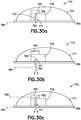
- An illustrative embodiment of an adhesive removal apparatus can be adhere to skin with an adhesive pad having an adhesive.
- the adhesive removal apparatus can comprise at least one adhesive solvent reservoir in a base of a body of the device, the at least one adhesive solvent reservoir containing adhesive solvent.
- the adhesive solvent can be releasable from the at least one adhesive solvent reservoir to act on the adhesive and release the adhesive pad from skin upon the device receiving a release signal.
- the adhesive solvent can be encapsulated in the at least one adhesive solvent reservoir.
- the adhesive solvent can flow through at least one hole in the base of the body of the device when the adhesive solvent is released.
- the adhesive solvent can be at least partially comprised of siloxane.
- the adhesive solvent can contact and dissolve the adhesive from the adhesive pad when the adhesive solvent is released.
- the adhesive solvent can wick to the adhesive pad and dissolve the adhesive from the adhesive pad.
- communications between devices are preferably wireless
- a person of ordinary skill in the art would readily appreciate other forms of communication, such as wired communication or a capacitive interface for communication through user tissue, such as skin.
- Illustrative embodiments of the present invention relate to wireless communication between a remote user interface, a primary On-Body Medical Device, and a preemptive On-Body Medical Device that can be attached to a user's skin simultaneously with the primary On-Body Medical Device or at a later time, prior to the end of life of the On-Body Medical Device.
- illustrative embodiments of the invention can contain and/or infuse insulin or any other medicament subcutaneously, intradermally, intramuscularly or otherwise.
- subcutaneous infusion is merely exemplary, and embodiments of the invention may deliver fluid intradermally, intramuscularly or otherwise.
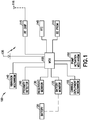
- an OBMD 100 generally includes a microprocessor control unit (MCU) 105, a memory (e.g., EEPROM) 110, an RF chip 115 and antenna 116, a battery 120, a battery monitor 125, a reservoir monitor 130, a light emitting diode (LED) 135, a vibration mechanism 140, a real time clock (RTC) 145, a pump activation mechanism 150, a cannula deployment mechanism 155, and a proximity detector 160.
- MCU microprocessor control unit
- EEPROM electrically erasable programmable read-only memory
- RF chip 115 and antenna 116 e.g., RF chip 115 and antenna 116
- battery 120 e.g., a battery monitor 125, a reservoir monitor 130, a light emitting diode (LED) 135, a vibration mechanism 140, a real time clock (RTC) 145, a pump activation mechanism 150, a cannula deployment mechanism 155, and a proximity detector 160
- the MCU 105 of the OMBD 100 is programmed to retrieve and execute instructions stored in the memory 110 to operate the OMBD 100 and activate the subcutaneous delivery of controlled amounts of insulin at set and variable rates to a user.
- processor(s) known to those of ordinary skill in the art such as an integrated circuit microprocessor, microcontroller, a digital signal processor (DSP), and/or a central processing unit (CPU), or other circuit or equivalent capable of interpreting instructions or performing logical actions on information, can be used in conjunction with illustrative embodiments of the present invention.
- the memory 110 of the OBMD 100 stores instructions, medical device data, infusion programs and schedules, user log files, and any other data and parameters necessary for the OBMD 100 to operate as intended.
- the memory 110 operating in conjunction with the present invention may include any combination of different memory storage devices, such as hard drives, random access memory (RAM), read only memory (ROM), FLASH memory, or any other type of volatile and/or nonvolatile memory.
- the RF chip 115 of the OBMD 100 is a two-way communication interface, including a receiver and a transmitter, for communicating with a remote user interface (UI) and another OBMD using radio frequency or other wireless communication standards and protocols.
- UI remote user interface
- ZigBee or any other WPAN protocol based on IEEE802.15.4, provides standardized, secure medical device communication in several widely available radio frequency allocations.
- the battery 120 supplies power to the MCU 105.
- the battery is preferably integrated into the OBMD 100 or can be provided as a replaceable battery.
- a battery of any suitable type and size may be used.
- the battery monitor 125 of the OMBD 100 determines whether the battery 120 is installed and monitors the level of voltage of the battery 120.
- the battery monitor 125 is adapted to report the presence or absence of an installed battery and compute or measure the amount of voltage stored in the installed battery. Additionally, if the battery 120 has a voltage capacity less than a predetermined threshold, the battery monitor 125 issues an alert to at least one of the OBMD 100 and a remote UI in the form of at least one of optical, acoustic, or tactile indications.
- Optical indication may be provided by a liquid crystal display (LCD), but may also be provided by other optical indicators such as a color light emitting diodes (LED) 135, organic light-emitting diodes (OLED), display text, display background colors, display backlight colors, and the like.
- Audible indication may be provided by a low power alarm, buzzer, or the like.
- Tactile indication may be provided by a vibratory mechanism 140, such as a piezo actuator.
- the reservoir monitoring unit 130 is adapted to compute the volume of insulin stored by a reservoir of the OBMD 100. If the reservoir volume reaches a level less than a predetermined threshold, the reservoir monitor 125 issues an alert to at least one of the OBMD 100 and a remote U I in the form of at least one of an optical or an acoustic indication.
- the RTC 145 which is a programmable clock for providing programs with real-time to track and control insulin delivery and initiate alarms at specific intervals, is utilized as part of the synchronization of the devices in illustrative embodiments of the present invention.
- the pump activation mechanism 150 is adapted to deliver and meter insulin doses from the reservoir through a cannula that is inserted beneath the skin of a user when activated by the MCU 105.
- the cannula deployment mechanism 155 is adapted to insert a cannula beneath the skin of a user when activated by instructions from a remote UI or, in the absence of a remote UI, instructions from another OMBD.
- the proximity detector 160 is provided to extend product shelf-life and improve patient data security of RF-controlled devices having factory-installed, non-accessible primary-cell batteries.
- the proximity detector 160 communicates in lieu of the normal RF link for the purpose of initial synchronization and pairing with another medical device.
- the proximity detector drawing its operating power from the signal itself, remains ready to detect at all times without consuming any battery power at all. This improves responsiveness while extending shelf life of the OBMD 100.
- the proximity detector 160 is described more in detail in U.S. provisional patent application Serial No.
- FIG. 2-8 depict two illustrative embodiments of an OBMD of the present invention.
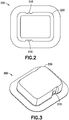
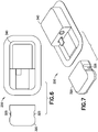
- Figs. 2-8 depict a completely disposable patch pump 200 and a durable/disposable patch pump 250.
- Features of completely disposable patch pump 200 are shown on Figs. 2-3 and include integral push-buttons 215 and an upper housing 220.
- Features of durable/disposable patch pump 250 are shown on Figs. 4-8 and include a first upper housing 320, integral push-buttons 325, a second upper housing 340, an electrical connector 345 and O-ring seals 390.
- One or more push-buttons can be used to activate a manual bolus. Using more than one push-button may however reduce the chance of unintentional activation. For example, two opposing push buttons can be adapted to activate a manual bolus if pressed simultaneously.
- Fig. 9 depicts an illustrative assembly embodiment of the completely disposable patch pump 200.
- the completely disposable patch pump includes a reservoir 201, a reservoir septum 205, a guide 210, integral push-buttons 215, an upper housing 220, a battery 225, a catheter deployment assembly 230, a printed circuit board assembly (PCBA) 235, a lower housing 240, a pressure sensitive adhesive 245, a pump engine 255, and a fluidic assembly 260.
- PCBA printed circuit board assembly
- the completely disposable patch pump 200 is disposed of after a single use by a user.
- An antenna may be part of a PCBA or a separate component electrically connected to the PCBA.
- Fig. 10 depicts an illustrative assembly embodiment of the durable/disposable patch pump 250.
- the durable/disposable patch pump 250 includes a durable assembly 251 including a pump engine 300, a first lower housing 305, connector traces 310, a PCBA 315, a first upper housing 320, integral push-buttons 325, and a dovetail feature 330.
- the durable/disposable patch pump 250 also includes a disposable assembly 252 including a dovetail feature 335, a second upper housing 340, a connector 345, a battery 350, a PCBA 355, a catheter deployment assembly 360, a reservoir septum 365, a reservoir 370, a fluidic assembly 375, a second lower housing 380, a Pressure-Sensitive Adhesive (PSA) 385, and O-ring seals 390.
- An antenna may be part of a PCBA or a separate component electrically connected to the PCBA.
- Dovetail feature 330 or any other coupler known in the art, can be used to couple the durable assembly and the disposable assembly.
- the durable and disposable assemblies 251, 252 of the durable/disposable patch pump 250 are connected via the channels of the dovetail feature 330, 335 and the connector 345 prior to application to the skin of a user.
- the disposable assembly 252 of the patch pump 250 is disposed of after a single exhaustive use by a user.
- the durable assembly 251 of the patch pump 250 is reusable when connected to another non-empty disposable assembly.
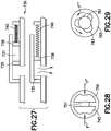
- Fig. 11 depicts an illustrative embodiment of the catheter deployment assembly 230, 360 for embodiments of the patch pumps 200 and 250 adapted to insert a catheter beneath the skin of a user when activated by instructions from a remote UI or, in the absence of a remote UI, instructions from another OMBD.
- the catheter deployment assembly 230, 360 includes an introducer needle 400, a catheter 405, a deployment carriage 410, a deployment spring (not shown), a retraction carriage 415, a retraction spring (not shown), and a tubing port 420.
- a remote UI 500 generally includes a microprocessor control unit (MCU) 505, a memory (e.g., EEPROM) 510, a RF chip 515 and antenna 516, a battery 520, a battery monitor 525, a speaker, LED (not shown), vibrator 530, a real time clock (RTC) 535, a LCD 540, a wired interface (USB) 545, and a proximity transmitter 550.
- MCU microprocessor control unit
- EEPROM electrically erasable programmable read-only memory
- RTC real time clock
- LCD 540 a liquid crystal display
- USB wired interface
- the MCU 505 of the remote UI 500 is programmed to retrieve and execute instructions stored in the memory 510 to operate the remote UI 500.
- processor(s) known to those of ordinary skill in the art such as an integrated circuit microprocessor, microcontroller, a digital signal processor (DSP), and/or a central processing unit (CPU), or other circuit or equivalent capable of interpreting instructions or performing logical actions on information, can be used in conjunction with illustrative embodiments of the present invention.
- the memory 510 of the remote UI 500 stores instructions, medical device data, infusion programs and schedules, user log files, and any other data and parameters necessary for the remote UI 500 to operate as intended.
- the memory 510 operating in conjunction with the present invention may include any combination of different memory storage devices, such as hard drives, random access memory (RAM), read only memory (ROM), FLASH memory, or any other type of volatile and/or nonvolatile memory.
- the RF chip 515 of the remote UI 500 is a two-way communication interface, including a receiver and a transmitter, for communicating with another remote UI and at least one OBMD 100 using radio frequency or other wireless communication standards and protocols.
- the battery 520 supplies power to the MCU 505.
- a battery of any suitable type and size may be used.
- the battery monitor 525 of the remote UI 500 determines whether the battery 520 is installed and monitors the level of voltage of the battery 520. If the battery 520 has a voltage capacity less than a predetermined threshold, the battery monitor 525 issues an alert to the remote UI 500 in the form of at least one of an optical or an acoustic indication.
- Optical indication may be provided by a liquid crystal display (LCD) 540, but may also be provided by other optical indicators such as a color light emitting diodes (LED) 530, organic light-emitting diodes (OLED), display text, display background colors, display backlight colors, and the like.
- Audible indication may be provided through a speaker 530 by a low power alarm, buzzer, or the like.
- Tactile indication may be provided by a vibratory mechanism 530, such as a piezo actuator.
- the RTC 535 which is a programmable clock for providing programs with real-time to track and control insulin delivery and initiate alarms at specific intervals, is utilized as part of the synchronization of the devices in illustrative embodiments of the present invention.
- the wired interface 545 such as a universal serial bus (USB) is provided for connection, communication and power supply between electronic devices.
- USB universal serial bus
- the proximity transmitter 550 is provided to extend product shelf-life and improve patient data security of RF-controlled devices having factory-installed, non-accessible primary-cell batteries as addressed above.
- Figs. 13-14 depict two illustrative embodiments of a remote UI 500.
- UIs can be powered by primary cells, which would need to be replaced by the user periodically over the life of the UI.
- the UI can also be powered by secondary cells, also referred to as rechargeable cells.
- the life of secondary cells can be typically rated by the number of charge / discharge cycles, and these cells can last for a number of years.
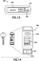
- Fig. 13 depicts an illustrative embodiment of a fully-functioning GUI 555.
- the fully-functioning GUI 555 has all available features necessary to control and administer the fluid delivery system of the present invention including the ability to communicate wirelessly with a health care network, either directly through the cellular network or indirectly through a PC or smartphone attached to the GUI using USB or Bluetooth, Bluetooth LE, ZigBee, or a custom communication protocol.
- Fully-functioning GUI 555 includes "up” and “down” buttons 566 to control the fluid delivery system, button 567 and display 568.
- Fig. 14 depicts an illustrative embodiment of a minimally-functioning key fob 560.
- the primary purpose of the key fob 560 is to enable discrete bolus control and provide alarms when the user is in public.
- the key fob 560 mimics an insulin pen known to those of ordinary skill in the art.
- the user can turn an end dial 561, visualize the dose on display 562, and depress the button 563 on the end similarly to depressing a button on an insulin pen.
- End dial 561 can instead be any dose setting device adapted to set a bolus dose.
- the design of the key fob 560 is also similar to the user interface portion of an insulin pen.
- the key fob 560 has a body cross section, a dial for adjustment, a size graphics on the LCD screen, and a resistance to turning in the dial similar to those on an insulin pen.
- the overall length of the key fob 560 is similar to that of a house key.
- the key fob 560 includes a safety feature, e.g., a secondary push-button 564 or other button combined with a timer function to enable bolus infusions at predetermined intervals, and an additional safety feature to limit the maximum bolus delivered during a specific period of time.
- An illustrative key fob can be used to set and deliver a bolus.
- a key fob can provide discrete bolus delivery functions when a user is in public. While embodiments of the minimally-functioning key fob described herein include bolus functions only, those of ordinary skill in the art will readily appreciate that the minimally functioning key fob could include the ability to adjust a basal rate in addition to setting a bolus dose.
- insulin doses are typically administered at a basal rate and in a bolus dose.
- Basal insulin is delivered continuously over period of time, and strives to keep one's blood glucose levels in a consistent range between meals and overnight.
- Some insulin pumps are capable of programming the basal rate of insulin to vary according to the different times of the day and night.
- Bolus doses are typically administered when the user takes a meal, and generally provide a single additional insulin injection to balance the carbohydrates consumed.
- Some conventional insulin pumps enable the user to program the volume of the bolus dose in accordance with the size or type of the meal consumed.
- Conventional insulin pumps also enable a user to take in a correctional or supplemental bolus of insulin to compensate for a low blood glucose level at the time the user is calculating a meal bolus.
- An illustrative embodiment of a system for on-body fluid delivery can include a primary patch pump adapted to attach a first infusion cannula to a user, the primary patch pump further adapted to perform a plurality of primary patch pump functions, and a secondary patch pump adapted to attach a second infusion cannula to a user, the secondary patch pump further adapted to perform a plurality of secondary patch pump functions substantially similar to the plurality of primary patch pump functions if an error condition associated with the primary patch pump is determined.
- the plurality of primary patch pump functions can include at least one of pairing with a primary user interface, being filled with a medicament and primed, deploying a catheter, initiating a bolus dose or basal rate, entering a primary patch pump SLEEP mode, entering a primary patch pump WAKE mode at predetermined primary patch pump WAKE time intervals, and entering a primary patch pump SNIFF mode for up to a predetermined primary patch pump SNIFF time.
- a power level associated with a primary or secondary patch pump SLEEP mode can be lower than a power level associated with a primary or secondary patch pump WAKE mode.
- the primary user interface can include a primary user interface real-time clock
- the primary patch pump can include a primary patch pump real-time clock.
- At least one of a SLEEP cycle, a WAKE cycle and a SNIFF cycle of the primary user interface can be synchronized with at least one of a SLEEP cycle, a WAKE cycle and a SNIFF cycle of a primary patch pump to save energy, using the primary user interface real-time clock and the primary patch pump real-time clock. Synchronization can be performed using a real-time clock.
- the primary patch pump can be communicatively couplable to the secondary patch pump.
- the primary patch pump can include one of a completely disposable patch pump and a durable/disposable patch pump.
- the completely disposable patch pump can include a reservoir to contain medicament, at least one integral push-button to activate a bolus dose, a catheter deployment assembly to deploy a catheter, a pump engine to infuse medicament from the reservoir through the deployed catheter, a printed circuit board assembly to control operations of at least one of the catheter deployment assembly and the pump engine, and an adhesive to attach the system to skin.
- the integral push-buttons can include two push-buttons to activate a bolus dose if both push-buttons are depressed simultaneously.
- the durable/disposable patch pump can include a durable assembly and a disposable assembly, wherein the durable assembly includes a pump engine to infuse medicament from the reservoir, at least one integral push-button to activate a bolus dose, and a coupler feature to couple the durable assembly to the disposable assembly, and wherein the disposable assembly includes: a coupler feature to couple the disposable assembly to the durable assembly, a connector to electrically connect the disposable assembly to the durable assembly, a catheter deployment assembly to deploy a catheter, a reservoir to contain medicament, and an adhesive to attach the system to skin, and wherein at least one of the durable assembly and the disposable assembly includes a printed circuit board assembly to control operations of at least one of the pump engine and the catheter deployment assembly.
- the integral push-buttons can include two push-buttons to activate a bolus dose if both push-buttons are depressed simultaneously.
- At least one of a primary user interface and a secondary user interface couplable to one or more patch pumps can include one of a fully-functioning graphical user interface and a minimally-functioning key fob.
- At least one of the primary user interface and the secondary user interface can include a timer function enabling bolus infusions at predetermined intervals.
- the minimally-functioning key fob can include a dose setting device, such as a turnable dial, adapted to set a bolus dose, and at least one depressible button adapted to initiate a bolus dose.
- a primary user interface can be communicatively couplable to at least one of the primary patch pump and the secondary patch pump.
- the primary user interface can be communicatively couplable to a network link.
- a secondary user interface communicatively can be couplable to at least one of the primary patch pump and the secondary patch pump.
- FIG. 15-21 Illustrative embodiments for systems and methods of on-body fluid delivery of the present invention are depicted in Figs. 15-21 .
- Fig. 15 depicts an illustrative embodiment of a system for on-body fluid delivery in accordance with illustrative embodiments of the present invention, including a primary patch pump 605, a primary UI 600 and a network link 602.
- Primary patch pump 605 can include, for example, a wearable medical device patch pump glucose sensor.
- Primary UI 600 can include, for example, a graphical user interface, a personal data assistant or a cell phone application.
- Network link 602 can include, for example, a network link of personal computer, a network link of a mobile device, a network link of a cellular device, an internet link, and a gateway to a network such as a medical network.
- Fig. 16 depicts an illustrative embodiment of a system for on-body fluid delivery between a primary UI 600 and a primary patch pump 605.
- Fig. 17 depicts an illustrative embodiment of a wireless system for on-body fluid delivery between a combination of a primary UI 600, a primary patch pump 605, and a secondary patch pump 610.
- Fig. 18 depicts an illustrative embodiment of a wireless system for on-body fluid delivery between a primary patch pump 605 and a secondary patch pump 610.
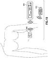
- Fig. 19 depicts another illustrative embodiment of a wireless system for on-body fluid delivery between a combination of a primary UI 600, a secondary UI 615, and a primary patch pump 605.
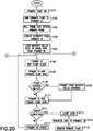
- Fig. 20 depicts a flow chart illustrating an illustrative method of on-body fluid delivery between a combination of a primary UI and a primary patch pump.
- a primary patch pump 605 is turned ON in step S101.
- the primary patch pump 605 is paired to the primary UI 600 in step S102.
- the pairing and the unique identifier for the pairing are assigned to the devices to enable secure, synchronized, encrypted wireless communication and minimize or eliminate cross-talk with other systems within the broadcast range.
- step S103 the user then proceeds to fill the primary patch pump's reservoir with insulin, prime the primary patch pump 605 from the primary UI 600, and attach the primary patch pump 605 to the user's skin surface in step S103.
- the user can now deploy the catheter of the primary patch pump 605 from the primary UI 600 in step S104 to deliver incremental basal infusion.
- step S105 the user initiates a bolus dose or basal rate. For example if the user initiates a basal rate of 2 units/hr from the primary UI 600, the primary UI 600 instructs the primary patch pump 605 to infuse a basal rate of approximately 0.5 units every 15 minutes.
- step S106 primary UI 600 and primary patch pump 605 go to "SLEEP".
- the primary UI 600 and primary patch pump 605 "WAKE” approximately once per minute as shown in step S107. If upon “waking", the primary patch pump 605 detects the primary UI 600 in active mode, then the primary patch pump 605 temporarily enters an "improved-response-time” mode with somewhat increased power consumption.
- step S108 the primary patch pump 605 communicates with the primary UI 600 to determine whether the user initiated a mealtime bolus during the last cycle. If so, the primary patch pump 605 will begin a bolus infusion of 1 unit/min, for example, as shown in step S109.
- the primary patch pump 605 will "SNIFF" for up to one second or a predetermined time in step S110 and check for an error condition in step S111.
- An error condition can comprise of one or more of conditions such as catheter occlusion, low reservoir, end of reservoir, battery depleted, battery failure, catheter deployment, entrapped air, and leakage.
- the "SLEEP,” “WAKE,” and “SNIFF” cycles are constantly ongoing at regular intervals in the background and are transparent to the user. If the user engages the primary UI 600 to adjust basal rate or set a bolus delivery, the primary UI 600 immediately wakes, but after adjustment or setting remains synchronized to the "SLEEP,” “WAKE,” and “SNIFF" cycles of the primary patch pump 605.
- the primary patch pump 605 exchanges relevant data with the primary UI 600 such as transferring an infusion profile update to the primary UI 600, receiving infusion commands from the primary UI 600, such as bolus dose requirements or basal rate adjustment, delivering the bolus dose and making any adjustments to the basal rate, and transmitting confirmation of delivery and/or adjustment at step S112 and steps S106 to S112 are repeated until an error condition occurs.
- Relevant data can comprise data indicative of at least one an infusion profile update, an infusion command, a bolus dose, a bolus dose requirement, a basal rate, a basal rate adjustment, a confirmation of delivery, an error state or condition, and a confirmation of adjustment.
- step S113 If an error condition exists in step S113, the primary patch pump 605 will alert the user in step S113 and communicates relevant data to the primary UI in step S114. The primary patch pump 605 is now ready to be removed in step S115.
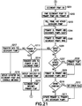
- Fig. 21 depicts a flow chart illustrating an illustrative wireless method of on-body fluid delivery between a combination of a primary UI, a primary patch pump, and a secondary patch pump.
- a user preemptively turns ON the secondary patch pump 610 on the last cyclical day of the primary patch pump 605 in step S201.
- the secondary patch pump 610 is paired to both the primary UI 600 and the primary patch pump 605 in step S202. The user then proceeds to fill the secondary patch pump's reservoir with insulin, prime the secondary patch pump 610 from the primary UI 600, and attach the secondary patch pump 610 to the user's skin surface in step S203.
- both the primary patch pump 605 and the secondary patch pump 610 are simultaneously attached to the user's skin surface.
- the catheter of secondary patch pump 610 is not yet deployed at this time.
- the primary UI 600, the primary patch pump 605 and the secondary patch pump 610 "SLEEP,” “WAKE,” and “SNIFF" together in steps S204, S205, and S209.
- step S207 the user may initiate a bolus dose as shown in step S207 that will trigger the primary patch pump 605 to initiate a bolus does as shown in step S208 during the next "WAKE" cycle of step S205.
- the secondary patch pump 610 will remain awake until the bolus dose has been delivered. If there is insufficient insulin in the reservoir of the primary patch pump 605, then the secondary patch pump 610 will activate, deploy its catheter, and complete the bolus delivery.
- the "SLEEP,” “WAKE,” and “SNIFF” cycles are constantly ongoing at regular intervals in the background and are transparent to the user. If the user engages the primary UI 600 to adjust basal rate or set a bolus delivery, the primary UI 600 immediately wakes, but after setting or adjustment remains synchronized to the "SLEEP,” “WAKE,” and “SNIFF" cycles of the primary and secondary patch pumps 605, 610.
- step S210 If no error condition is detected in step S210, then the primary UI 600, the primary patch pump 605, and the secondary patch pump 610 are updated with the latest relevant data at step S211 and steps S204-S211 are repeated until an error condition occurs and an error flag is detected at step S206. If an error condition occurs at step S210, an error flag is set at step S212, the primary UI 600, the primary patch pump 605, and the secondary patch pump 610 are updated with the latest relevant data at step S211 and steps S204-S211 are repeated until an error condition occurs.
- the error flag is present at step S206, thus initiating a transfer from the primary patch pump 605 to the secondary patch pump 610.
- the primary UI 600 is detected in step S213, then the primary patch pump 605 communicates relevant data to the primary UI 600 and the secondary patch pump 610.
- the primary UI 600 then deploys the catheter on the secondary patch pump 610 at step S215.
- the secondary patch pump 610 takes over the role of a primary patch pump at step S216.
- another preemptive patch pump can be attached to the user and can take over the role of a secondary patch pump.
- the primary patch pump 605 communicates relevant data to the secondary patch pump 610 at step S217. Accordingly, the catheter is deployed on the secondary patch pump 610 and infusion continues via the secondary patch pump 610 at step S218.
- a "SLEEP” mode can be associated with a power consumption level lower than ta power consumption level associated with a "WAKE” mode. Since the "SLEEP" duration can be minutes long, the background on the LCD screen 540 on the Uls 600, 615 can change colors to correspond to "dose requested" (yellow), to "dose delivered” (green), and red for a failure condition or alarm to eliminate confusion for the user as to whether the dose has been communicated and delivered. When these states do not need to be communicated to the user, there is no color to the background of the LCD screens of the Uls 600,615 and the LCD 540 can turn off, as is the case for "sleep" mode. Audible and tactile signals can also be provided for the three states described above, which are distinctly different for each condition.
- an additional secondary UI 615 may be activated.
- a secondary UI 615 such as a key fob 560, may be used as an additional tool to wirelessly enable discrete bolus control and provide alarms when the user is in public.
- the primary UI 600 is dominant.
- UI1 preferably assumes the dominant role.
- a duration can be established (e.g., 30 seconds) to continue to "sniff' for primary UI 600, after which time secondary UI 615 can provide a command to the patch pumps 605, 610.
- the two Uls 600, 615 should not both be enabled to provide commands to the patch pump at the same time.
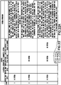
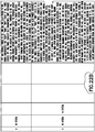
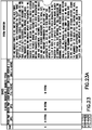
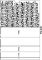
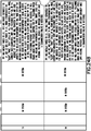
- Figs. 22-24 depict illustrative embodiments of fourteen different states 1-14 and operations for activated medical devices of the fluid delivery system of the present invention.
- the system operation associated with each different combination of a primary patch pump (Patch Pump 1 or PP1), a secondary patch pump (Patch Pump 2 or PP2), a primary UI (User Interface 1 or UI1), and a secondary UI (User Interface 2 or UI2) is disclosed in the state diagram table in Figs. 22-24.
- Figs. 22-24 also depict illustrative embodiments where communications failure can occur (e.g., states where patch pump 1 is not recognized by the other devices in the system when all the devices wake) and how embodiments of the present invention continue to provide safe, uninterrupted therapy to a user.
- an illustrative system includes PP1.
- Illustrative system Operations can proceed as follows. PP1 was initially paired to UI1, which synchronized the "sleep", “wake”, “sniff" cycle of both devices. In the absence of UI1, PP1 will wake, conduct self-diagnostics, sniff for the UI1, and then return to sleep. PP1 continues to provide basal infusion at the rate previously transmitted from the UI. Bolus delivery can be initiated manually by the user via the push-buttons on PP1.
- an illustrative system includes PP1 and UI1.
- Illustrative system Operations can proceed as follows. PP1 was initially paired to UI1, which synchronized the "sleep", “wake”, “sniff” cycle of both devices. PP1 will wake, conduct self-diagnostics, sniff, recognize UI1, transfer the infusion profile update which occurred since the previous update was transmitted, receive infusion commands, e.g. bolus dose requirement or basal rate adjustment, deliver the bolus dose and make any adjustments to the basal rate, transmit confirmation of delivery and / or adjustment, and then return to sleep.
- infusion commands e.g. bolus dose requirement or basal rate adjustment
- an illustrative system includes PP1, UI1 and UI2.
- Illustrative system Operations can proceed as follows. PP1 was initially paired to UI1, and UI2 was also paired to UI1, which synchronized the "sleep", “wake”, “sniff' cycle of all three devices. PP1 will wake, conduct self-diagnostics, sniff, recognize both UI1 and UI2, PP1 will transfer to both UIs the infusion profile update which occurred since the previous update was transmitted. However, in the presence of both Uls, PP1 will only receive infusion commands from UI1, e.g. bolus dose requirement or basal rate adjustment. Following the delivery of the bolus dose and any required adjustments to the basal rate, PP1 will transmit confirmation of delivery and / or adjustment, and then return to sleep.
- UI1 e.g. bolus dose requirement or basal rate adjustment
- an illustrative system includes PP1 and UI2. Illustrative system Operations can proceed as follows. PP1 was initially paired to UI1, and UI2 was also paired to UI1, which synchronized the "sleep", “wake”, “sniff' cycle of all three devices. PP1 will wake, conduct self-diagnostics, sniff, recognize only UI2. In the absence of UI1, PP1 will transfer to UI2 the infusion profile update which occurred since the previous update was transmitted. Since UI2 can only provide a single infusion command, i.e.
- PP1 will receive the bolus dose command from UI2, and following the delivery, PP1 will transmit confirmation of delivery to UI2, and then return to sleep. Either UI2 or PP1 will update UI1, the next time UI1 is recognized as the devices in the system continue to wake, sniff, and sleep.
- an illustrative system includes PP1 and PP2.
- Illustrative system Operations can proceed as follows. PP1 was initially paired to UI1, and PP2 was also paired separately to UI1, which synchronized the "sleep", “wake”, “sniff" cycle of all three devices. In the absence of UI1, PP1 will wake, conduct self-diagnostics, sniff for UI1 and any other devices to which PP1 has been paired, transfer to PP2 the infusion profile update which occurred since the previous update was transmitted, and then return to sleep.
- Bolus delivery can be provided manually by the user.
- PP1 If a manual bolus command is provided by the user to PP1, then upon waking both PP1 and PP2 will remain awake until the complete bolus dose has been delivered. If there is insufficient insulin remaining in the reservoir of PP1, PP1 will communicate the remaining requirement to PP2, and the basal deliver rate. PP2 will then deploy the infusion catheter, deliver the remainder of the bolus dose, and return to sleep. After receiving confirmation from PP2, PP1 will disable all infusion capability and return to the synchronized sleep, wake, sniff cycle. PP2 will now operate as PP1 in state 1, and continue to provide basal infusion, and manually actuated, incremental bolus dosing.
- PP2 will update UI1, and then PP2 and UI1 will operate as PP1 and UI1 in state 2.
- the catheter in PP1 can be automatically retracted and the adhesive can be automatically dissolved from a command provided by UI1, or PP1 can be manually removed from the skin surface of the user.
- an illustrative system includes PP1, PP2 and UI1.
- Illustrative system Operations can proceed as follows. PP1 was initially paired to UI1, and PP2 was also paired separately to UI1, which synchronized the "sleep", “wake”, “sniff” cycle of all three devices. Together PP1 and PP2 will wake, conduct self-diagnostics, sniff, and recognize UI1. PP1 will transfer to UI1 the infusion profile update which occurred since the previous update was transmitted. UI1 will transfer to PP2 the infusion profile update which occurred since the previous update was transmitted. PP1 will receive infusion commands from UI1. These may include adjustments to the basal rate or bolus infusion commands.
- PP1 will transmit confirmation of delivery and/or adjustment to UI1, and UI1 will in turn transmit the update to PP2, and then all three devices will return to sleep. If there is insufficient insulin remaining in the reservoir of PP1 to complete the required bolus delivery or if PP1 is exhausted during basal delivery, PP1 will communicate the remaining requirement to UI1. After receiving confirmation from UI1, PP1 will disable all infusion capability and return to the synchronized sleep, wake, sniff cycle. UI1 will then transfer the remaining bolus requirements and/or basal rate to PP2. PP2 will then deploy the infusion catheter, take over basal rate infusion and/or deliver the remainder of the bolus dose, transmit confirmation of the remaining bolus dose, and return to sleep. PP2 will now operate as PP1 in state 2.
- an illustrative system includes PP1, PP2, UI1 and UI2.
- Illustrative system Operations can proceed as follows. PP1 was initially paired to UI1, PP2 was paired separately to UI1, and UI2 was also paired to UI1, which synchronized the "sleep", “wake”, “sniff” cycle of all four devices. Together PP1 and PP2 will wake, conduct self-diagnostics, sniff, and recognize both UI1 and UI2. PP1 will transfer to both Uls the infusion profile update which occurred since the previous update was transmitted. UI1 will transfer to PP2 the infusion profile update which occurred since the previous update was transmitted. In the presence of both Uls, PP1 will receive infusion commands from UI1.
- PP1 will transmit confirmation of delivery and / or adjustment to both UI1 and UI2, and UI1 will in turn transmit the update to PP2, and then all four devices will return to sleep. If there is insufficient insulin remaining in the reservoir of PP1 to complete the required bolus delivery or if PP1 is exhausted during basal delivery, PP1 will communicate the remaining requirement to UI1. After receiving confirmation from UI1, PP1 will disable all infusion capability and return to the synchronized sleep, wake, sniff cycle. UI1 will then transfer the remaining bolus requirements and/or basal rate to PP2.
- PP2 will then deploy the infusion catheter, take over basal rate infusion and/or deliver the remainder of the bolus dose, transmit confirmation of the remaining bolus dose and resumption of basal delivery, and all four devices will return to sleep.
- PP2 will now operate as PP1 in state 3. The user can attach a new patch pump, which will take over the role of preemptive patch pump PP2.
- an illustrative system includes PP1, PP2 and UI2.
- Illustrative system Operations can proceed as follows. PP1 was initially paired to UI1, PP2 was paired separately and UI1, and UI2 was also paired to UI1, which synchronized the "sleep", “wake”, “sniff" cycle of all four devices. Together PP1 and PP2 will wake, conduct self-diagnostics, sniff, and recognize only UI2. PP1 will transfer to UI2 the infusion profile update which occurred since the previous update was transmitted. UI2 will transfer to PP2 the infusion profile update which occurred since the previous update was transmitted. In the absence of UI1, PP1 will receive bolus infusion commands from UI2.
- PP1 will transmit confirmation of delivery and/or adjustment to UI2, and UI2 will in turn transmit the update to PP2, and then all three devices will return to sleep. If there is insufficient insulin remaining in the reservoir of PP1 to complete the required bolus delivery or if PP1 is exhausted during basal delivery, PP1 will communicate the remaining requirement to UI2. After receiving confirmation from UI2, PP1 will disable all infusion capability and return to the synchronized sleep, wake, sniff cycle. UI2 will then transfer the remaining basal rate and/or bolus dose requirement to PP2.
- PP2 will deploy the infusion catheter, take over basal rate infusion and/or deliver the remainder of the bolus dose, transmit confirmation of the bolus dose and resumption of basal delivery, and all three devices will return to sleep.
- PP2 will now operate as PP1 in state 4. If upon waking PP2 recognizes UI1, then PP2 and UI1 will operate as PP1 and both UIs in state 3, and either UI2 or PP2 will update UI1, the next time UI1 is recognized as the devices in the system continue to wake, sniff, and sleep.
- an illustrative system includes UI1.
- Illustrative system Operations can proceed as follows. If upon waking, UI1 does not recognize a PP, then an alarm is provided to the user.
- an illustrative system includes UI2.
- Illustrative system Operations can proceed as follows. If upon waking, UI2 does not recognize a PP, then an alarm is provided to the user.
- an illustrative system includes UI1 and UI2.
- Illustrative system Operations can proceed as follows. If upon waking, both UI1 and UI2 do not recognize a PP, then an alarm is provided to the user.
- an illustrative system includes PP2 and UI1. Illustrative system Operations can proceed as follows. PP1 was initially paired to UI1, and PP2 was also paired separately to UI1, which synchronized the "sleep", “wake” "sniff' cycle of all three devices. PP2 will wake, conduct self-diagnostics, sniff, and recognize only UI1. In the absence of PP1. UI1 will transfer to PP2 any user updates for bolus dose requirement, basal rate, or basal rate adjustment. PP2 will then deploy the infusion catheter, deliver the bolus dose, transmit confirmation of the bolus dose delivery and resumption of basal delivery, and return to sleep. PP2 will now operate as PP1 in state 2.
- UI1 will provide an alarm or any other visual, audio or tactile alert mechanism known in the art to alert the user that PP1 is no longer functioning properly and should ⁇ be removed.
- UI1 will remain awake for two cycles sniffing for PP1, following which UI1 will resume the synchronized sleep, wake sniff cycle. (PP1 internal protocols will disable all infusion capability once a communication failure is detected.)
- an illustrative system includes PP2 and UI2. Illustrative system Operations can proceed as follows. PP1 was initially paired to UI1, PP2 was paired separately to UI1 and UI2 was also paired to UI1, which synchronized the "sleep", “wake”, “sniff" cycle of all four devices. PP2 will wake, conduct self-diagnostics, sniff, and recognize only UI2, In the absence of PP1 and UI1, UI2 will transfer to PP2 any user updates for bolus dose requirement. PP2 will then deploy the infusion catheter, deliver the bolus dose, transmit confirmation of the bolus dose delivery and resumption of basal delivery, and return to sleep.
- PP2 will now operate as PP1 in state 3.
- UI2 will provide an alarm or any other visual, audio or tactile alert mechanism known in the art to alert the user that PP1 is no longer functioning properly and should be removed.
- UI2 will remain awake for two cycles sniffing for PP1, following which UI will resume the synchronized sleep, wake, snuff, cycle. (PP1 internal protocols will disable all infusion capability once a communication failure is detected.)
- an illustrative system includes PP2, UI1 and UI2.
- Illustrative system Operations can proceed as follows. PP1 was initially paired to UI1, PP2 was paired separately to UI1, and UI2 was also paired to UI1, which synchronized the "sleep", “wake”, “sniff" cycle of all four devices. PP2 will wake, conduct self-diagnostics, sniff and recognize only UI1 and UI2. In the absence of PP1, UI1 will transfer to PP2 any user updates for bolus dose requirement or basal rate adjustment. PP2 will then deploy the infusion catheter, deliver the bolus dose, transmit confirmation of the bolus dose delivery and resumption of basal delivery, and return to sleep.
- PP2 will now operate as PP1 in state 2.
- UI1 will provide an alarm to alert the user that PP1 is no longer functioning properly and should be removed.
- UI1 will remain awake for two cycles sniffing for PP1, following which UI1 will resume the synchronized sleep, wake, sniff cycle. (PP1 internal protocol will disable all infusion capability once a communication failure is detected.)
- the RTCs utilized in the medical devices of the fluid delivery system of the present invention can vary due to inherent limitations on accuracy and ambient conditions such as temperature and other factors.
- the maximum error in the current state of the art for RTCs is approximately 2 minutes per year, which equates to approximately one second over three days.
- An embodiment of the present invention overcomes the inherent limitations on accuracy of electronic clocks utilized in medical devices with wireless communication, such as RTCs, by controlling protocol timing incrementally, using only short intervals.
- the fluid delivery system provides a one second window each time the medical devices "WAKE" to enable all the devices to recognize the active devices in the system. For example, therapeutic functions cannot be executed until all the devices in the system are awake.
- the master device can re-synchronize all the devices in the system.
- a primary user interface can re-synchronize itself with a secondary user interface, a primary patch pump, and/or a secondary patch pump. This operation is transparent to the user, and advantageously assists in synchronizing the sleep and wake cycles of the different devices to improve battery management and prolong battery life.
- the user can initiate a bolus delivery from the UI while the OBMDs sleep, and upon waking the bolus will be delivered. Therefore, the user would not need to wait for the OBMDs to wake when the user is inputting a command into a remote UI.
- the primary patch pump can include a first reservoir adapted to contain a first fluid, a first catheter, a first pump adapted to infuse the first fluid from the first reservoir through the first catheter, and a first microcontroller adapted to control operations of the first pump.
- An illustrative method of on-body fluid delivery can include pairing the primary patch pump to the primary user interface.
- the primary patch pump can communicate with the primary user interface to determine whether user instructions have been received at the primary user interface. If it is determined that user instructions have been received at the primary user interface, machine instructions can be sent from the primary user interface to the primary patch pump according to the user instructions, and a bolus dose or basal rate can be initiated using the first microcontroller according to the machine instructions.
- An illustrative method of on-body fluid delivery can further include checking by the primary patch pump for an error condition. If an error condition is detected by the primary patch pump, a user can be alerted via an alert mechanism and transferring relevant data from the primary patch pump to the primary user interface. If no error condition is detected by the primary patch pump, relevant data can be transferred from the primary patch pump to the primary user interface. The method can return to the step of the primary patch pump communicating with the primary user interface.
- an error condition can include a condition indicative of at least one of a catheter occlusion, a low reservoir, an end of reservoir, a depleted battery, a battery failure, a catheter deployment, entrapped air and a leakage.
- Relevant data can include data indicative of at least one an infusion profile update, an infusion command, a bolus dose, a bolus dose requirement, a basal rate, a basal rate adjustment, a confirmation of delivery, an error state or condition, and a confirmation of adjustment.
- the primary user interface can re-synchronize the primary user interface and the primary patch pump.
- pairing the primary patch pump to the primary user interface can include assigning a first unique identifier to the primary user interface and a second unique identifier to the primary patch pump.
- An illustrative method of on-body fluid delivery can further include entering a primary patch pump SNIFF mode for up to a predetermined primary patch pump SNIFF time to check for an error condition.
- the primary patch pump can be attachable to skin.
- the first fluid can include insulin.
- An illustrative method of on-body fluid delivery can further include entering a primary user interface SLEEP mode by the primary user interface, entering a primary patch pump SLEEP mode by the primary patch pump, entering a primary user interface WAKE mode by the primary user interface at predetermined primary user interface WAKE time intervals, and entering a primary patch pump WAKE mode by the primary patch pump at predetermined primary patch pump WAKE time intervals.
- a power level associated with the primary user interface SLEEP mode can be lower than a power level associated with a primary user interface WAKE mode
- a power level associated with the primary patch pump SLEEP mode can be lower than a power level associated with a primary patch pump WAKE mode.
- a primary patch pump IMPROVED-RESPONSE-TIME mode can be entered by the primary patch pump to communicate with the primary user interface to determine whether user instructions have been received at the primary user interface.
- At least one of a SLEEP cycle, a WAKE cycle and a SNIFF cycle of the primary user interface can be synchronized with at least one of a SLEEP cycle, a WAKE cycle and a SNIFF cycle of the primary patch pump.
- a WAKE cycle and a SNIFF cycle of the primary user interface is synchronized with at least one of a SLEEP cycle, a WAKE cycle and a SNIFF cycle of the primary patch pump.
- An illustrative method of on-body fluid delivery can further include using a secondary patch pump communicatively couplable to at least one of the primary patch pump and the primary user interface.
- the secondary patch pump can include a second reservoir adapted to contain a second fluid, a second catheter, a second pump adapted to infuse the second fluid from the second reservoir through the second catheter, and a second microcontroller adapted to control operations of the second pump.
- An illustrative method of on-body fluid delivery can further include pairing the secondary patch pump to the primary user interface, and checking for an error flag. If no error flag is detected, the primary patch pump can communicate with the primary user interface to determine whether user instructions have been received at the primary user interface. If it is determined that user instructions have been received at the primary user interface, machine instructions can be sent from the primary user interface to the primary patch pump according to the user instructions, and a bolus dose or basal rate can be initiated using the first microcontroller according to the machine instructions.
- An illustrative method of on-body fluid delivery can further include checking for an error condition. If an error condition is detected, an error flag can be set. If no error condition is detected, relevant data can be transferred from the primary patch pump to the primary user interface and the secondary patch pump. The method can return to the step of checking for an error flag.
- an error condition can include a condition indicative of at least one of a catheter occlusion, a low reservoir, an end of reservoir, a depleted battery, a battery failure, a catheter deployment, entrapped air and a leakage.
- Relevant data can include data indicative of at least one an infusion profile update, an infusion command, a bolus dose, a bolus dose requirement, a basal rate, a basal rate adjustment, a confirmation of delivery, an error state or condition, and a confirmation of adjustment.
- An illustrative method of on-body fluid delivery can further include entering a primary patch pump SNIFF mode for up to a predetermined primary patch pump SNIFF time to check for an error flag.
- An illustrative method of on-body fluid delivery can further include continuing an infusion via the secondary patch pump if an error flag is detected.
- An illustrative method of on-body fluid delivery can further include, if an error flag is detected, determining whether the primary user interface is communicatively coupled to the primary patch pump. If no primary user interface is determined to be communicatively coupled to the primary patch pump, transferring relevant data from the primary patch pump to the secondary patch pump, and continuing an infusion via the secondary patch pump. If a primary user interface is determined to be communicatively coupled to the primary patch pump, relevant data can be transferred from the primary patch pump to the secondary patch pump and to the primary user interface, the secondary pump can be set as the primary pump, and the method can return to the step of the primary patch pump communicating with the primary user interface. Another preemptive patch pump can be set as the secondary patch pump.
- the primary patch pump can be attachable to skin.
- the primary user interface can re-synchronize the primary user interface and at least one of the primary patch pump and the secondary patch pump.
- pairing the secondary patch pump to the primary user interface can include assigning a third unique identifier to the secondary patch pump.
- the second fluid can include insulin.
- An illustrative method of on-body fluid delivery can further include entering a primary user interface SLEEP mode by the primary user interface, entering a primary patch pump SLEEP mode by the primary patch pump, entering a secondary patch pump SLEEP mode by the secondary patch pump, entering a primary user interface WAKE mode by the primary user interface at predetermined primary user interface WAKE time intervals, entering a primary patch pump WAKE mode by the primary patch pump at predetermined primary patch pump WAKE time intervals, and entering a secondary patch pump WAKE mode by the secondary patch pump at predetermined secondary patch pump WAKE time intervals.
- a WAKE cycle and a SNIFF cycle of the primary user interface can be synchronized with at least one of a SLEEP cycle, a WAKE cycle and a SNIFF cycle of the primary patch pump and with at least one of a SLEEP cycle, a WAKE cycle and a SNIFF cycle of the secondary patch pump to save energy.
- At least one of a SLEEP cycle, a WAKE cycle and a SNIFF cycle of the primary user interface can be synchronized with at least one of a SLEEP cycle, a WAKE cycle and a SNIFF cycle of the primary patch pump and with at least one of a SLEEP cycle, a WAKE cycle and a SNIFF cycle of the secondary patch pump to save energy.
- Additional embodiments of the present invention can overcome disadvantages such as the inconvenience and tissue damage caused by removing the adhesive backing 245, 385 of a patch pump from a user's skin surface as executed in step S115 of Fig. 20 .
- illustrative embodiments of the present invention leverage the power, circuitry and mechanization of a patch pump to control and release an adhesive solvent, such as siloxane, in order to minimize tissue damage and additional user steps needed to remove a patch pump device.
- An illustrative embodiment of an adhesive removal apparatus can be adhere to skin with an adhesive pad having an adhesive.
- the adhesive removal apparatus can comprise at least one adhesive solvent reservoir in a base of a body of the device, the at least one adhesive solvent reservoir containing adhesive solvent.
- the adhesive solvent can be releasable from the at least one adhesive solvent reservoir to act on the adhesive and release the adhesive pad from skin upon the device receiving a release signal.
- the adhesive solvent can be encapsulated in the at least one adhesive solvent reservoir.
- the adhesive solvent can flow through at least one hole in the base of the body of the device when the adhesive solvent is released.
- the adhesive solvent can be at least partially comprised of siloxane.
- the adhesive solvent can contact and dissolve the adhesive from the adhesive pad when the adhesive solvent is released.
- the adhesive solvent can wick to the adhesive pad and dissolve the adhesive from the adhesive pad.
- Fig. 25 depicts an illustrative embodiment of an adhesive removal apparatus 700 using multiple reservoir punctures.
- Adhesive solvent is encapsulated in several adhesive solvent reservoirs 701 in the base of a body 705 of a device adapted to adhere to skin.
- a release signal can trigger a force supplied by a shape memory alloy (SMA) wire, a motor, or the like.
- SMA shape memory alloy
- a force F moves the puncture ring 710 forward, thus piercing the adhesive solvent reservoirs 701. Force F can be triggered locally or remotely.
- the adhesive solvent then flows through holes 703 in the bottom of the base of the device body 705, contacts and then releases the adhesive pad from the skin.
- an adhesive solvent can wick through an adhesive as part of the adhesive dissolving process.
- a puncture ring can be movable to puncture the at least one adhesive solvent reservoir and release adhesive solvent.
- the puncture ring can be movable by a force.
- the force can be supplied by at least one of a memory wire, a spring and a motor. The force can be triggered by the release signal.
- Fig. 26 depicts an illustrative embodiment of an adhesive removal apparatus 720 using a heating element to release the solvent.
- the encapsulated solvent 721 is bonded over a micro-heating element 715 and a flow-hole 723 in the base of the device body 725.
- the micro-heating element 715 heats and ruptures a reservoir or encapsulations, allowing the solvent 721 to flow through the holes 723 to the adhesive.
- the heating element 715 is in direct contact with the encapsulation wall, and is small enough that the heating is not felt by the user.
- the adhesive solvent can be bonded over a micro-heating element heatable to rupture the at least one adhesive removal reservoir and release adhesive solvent.
- the micro-heating element can be activatable by the release signal.
- Fig. 27 depicts an illustrative embodiment of an adhesive removal apparatus 730 using a dual stopper mechanism.
- the solvent is on board the device in a solvent reservoir 731, trapped between two stoppers 735 and 736.
- the force mechanism 740 such as a SMA wire or another memory wire, or a triggered spring, a triggered preloaded spring, and the like, pushes the assembly forward from a solvent containing position to a solvent releasing position where solvent can flow through a hole.
- the front stopper 735 is past the flow-hole, solvent is forced out and into contact with the adhesive pad for easy removal of the adhesive pad from the skin.
- only one or any number of stoppers can be used.
- the at least one adhesive solvent reservoir can include at least one stopper movable from a solvent containing position to a solvent releasing position where adhesive solvent flows through at least one hole.
- the at least one stopper can be movable by a force.
- the force can be supplied by at least one of a memory wire, a spring and a motor. The force can be triggered by a release signal.
- Fig. 28 depicts an illustrative embodiment of an adhesive removal apparatus 750 using a squeeze chamber.
- the user can push sides of the device body 745 together, breaking the internal ampule of adhesive solvent.
- forces F' and F" can press sides of the device body together, thus breaking an internal ampule of adhesive solvent 751, which then wicks to and releases the adhesive pad 755.
- the at least one adhesive solvent reservoir can be disposed between two sides of the body of the device movable toward one another to break the at least one adhesive solvent reservoir and release adhesive solvent.
- the two sides are movable toward one another by a user gripping the body of the device.
- Fig. 29 depicts an illustrative embodiment of an adhesive removal apparatus 760 using a twist chamber.
- the user grips the device body 763 for removal, and can twist the device body, expelling adhesive solvent.
- circular forces F'" associated with a slight twist of the device body 763 compress and break an internal chamber 761. This releases the solvent, which then wicks to and releases the adhesive pad 765.
- the body of the device can be twistable with respect to the at least one adhesive solvent reservoir to break the at least one adhesive solvent reservoir and release adhesive solvent.
- the body of the device can be twistable by a user.
- Figs. 30a-c depicts illustrative embodiments of an adhesive removal apparatus 770 using motor activation.
- This embodiment uses a motor 771 and wireless capability already onboard a patch pump.
- a local, remote, wired or wireless controller can signal to infuse, retract, or release adhesive solvent.
- a cannula 775 of a patch pump is inserted into a user to supply insulin from the insulin reservoir and mechanization 776 in the device body 777 of the patch pump during normal operation.
- Cannula 775 can include a double-ended shaft.
- a front end 791 of cannula 775 is retracted from an infusion position 780, beyond a home position 785, as a back end 792 of cannula 775 of the double-ended shaft 791 of the cannula 775 moves to a solvent expel position 790 and punctures the adhesive solvent reservoir 795, allowing the solvent to flow into contact with the adhesive pad 796.
- the device includes a medicament reservoir containing medicament, wherein the medicament reservoir can be disposed above the adhesive pad and the at least one adhesive solvent reservoir can be disposed above the medicament reservoir, and at least one cannula comprising a double-ended shaft with a front end and a back end, wherein the at least one cannula can be movable from a home position of the front end to an infusion position of the front end to a solvent expel position of the back end.
- the individual components used in the exemplary patch pump embodiments disclosed herein can be based on existing designs and technologies which are known in the art.
- pump engines, fluidic assemblies and metering systems utilizing stepper motors, shape memory alloy (SMA) actuators, piezoelectric actuators, microelectromechanical systems (MEMS) devices, and directional control valves may be used.
- Fluid reservoirs may be rigid or deformable (e.g., with force applied by a movable plunger or preloaded spring).
Landscapes
- Health & Medical Sciences (AREA)
- Engineering & Computer Science (AREA)
- General Health & Medical Sciences (AREA)
- Public Health (AREA)
- Biomedical Technology (AREA)
- Medical Informatics (AREA)
- Epidemiology (AREA)
- Primary Health Care (AREA)
- Anesthesiology (AREA)
- Animal Behavior & Ethology (AREA)
- Heart & Thoracic Surgery (AREA)
- Veterinary Medicine (AREA)
- Vascular Medicine (AREA)
- Life Sciences & Earth Sciences (AREA)
- Hematology (AREA)
- Chemical & Material Sciences (AREA)
- Medicinal Chemistry (AREA)
- Bioinformatics & Cheminformatics (AREA)
- Business, Economics & Management (AREA)
- General Business, Economics & Management (AREA)
- Dermatology (AREA)
- Infusion, Injection, And Reservoir Apparatuses (AREA)
- Electrotherapy Devices (AREA)
Priority Applications (1)
| Application Number | Priority Date | Filing Date | Title |
|---|---|---|---|
| EP20162419.4A EP3682871A1 (en) | 2012-03-05 | 2013-03-05 | Apparatus for adhesive removal |
Applications Claiming Priority (2)
| Application Number | Priority Date | Filing Date | Title |
|---|---|---|---|
| US201261606929P | 2012-03-05 | 2012-03-05 | |
| PCT/US2013/029145 WO2013134279A1 (en) | 2012-03-05 | 2013-03-05 | Wireless communication for on-body medical devices |
Related Child Applications (2)
| Application Number | Title | Priority Date | Filing Date |
|---|---|---|---|
| EP20162419.4A Division-Into EP3682871A1 (en) | 2012-03-05 | 2013-03-05 | Apparatus for adhesive removal |
| EP20162419.4A Division EP3682871A1 (en) | 2012-03-05 | 2013-03-05 | Apparatus for adhesive removal |
Publications (3)
| Publication Number | Publication Date |
|---|---|
| EP2822543A1 EP2822543A1 (en) | 2015-01-14 |
| EP2822543A4 EP2822543A4 (en) | 2015-11-04 |
| EP2822543B1 true EP2822543B1 (en) | 2020-05-13 |
Family
ID=49117261
Family Applications (2)
| Application Number | Title | Priority Date | Filing Date |
|---|---|---|---|
| EP13757089.1A Active EP2822543B1 (en) | 2012-03-05 | 2013-03-05 | Wireless communication for on-body medical devices |
| EP20162419.4A Pending EP3682871A1 (en) | 2012-03-05 | 2013-03-05 | Apparatus for adhesive removal |
Family Applications After (1)
| Application Number | Title | Priority Date | Filing Date |
|---|---|---|---|
| EP20162419.4A Pending EP3682871A1 (en) | 2012-03-05 | 2013-03-05 | Apparatus for adhesive removal |
Country Status (7)
| Country | Link |
|---|---|
| US (2) | US9623173B2 (cg-RX-API-DMAC7.html) |
| EP (2) | EP2822543B1 (cg-RX-API-DMAC7.html) |
| JP (2) | JP6630475B2 (cg-RX-API-DMAC7.html) |
| CN (1) | CN204910157U (cg-RX-API-DMAC7.html) |
| CA (3) | CA3062048C (cg-RX-API-DMAC7.html) |
| ES (1) | ES2807895T3 (cg-RX-API-DMAC7.html) |
| WO (1) | WO2013134279A1 (cg-RX-API-DMAC7.html) |
Families Citing this family (59)
| Publication number | Priority date | Publication date | Assignee | Title |
|---|---|---|---|---|
| ES2354107T3 (es) | 2005-09-12 | 2011-03-10 | Unomedical A/S | Dispositivo de inserción para un equipo de infusión con una primera y segunda unidades de resorte. |
| US8352041B2 (en) * | 2006-11-28 | 2013-01-08 | The Alfred E. Mann Foundation For Scientific Research | Remote controls and ambulatory medical systems including the same |
| US7959598B2 (en) | 2008-08-20 | 2011-06-14 | Asante Solutions, Inc. | Infusion pump systems and methods |
| WO2011121023A1 (en) | 2010-03-30 | 2011-10-06 | Unomedical A/S | Medical device |
| WO2012123274A1 (en) | 2011-03-14 | 2012-09-20 | Unomedical A/S | Inserter system with transport protection |
| US9707337B2 (en) | 2011-09-13 | 2017-07-18 | Unitract Syringe Pty Ltd | Sterile fluid pathway connection to drug containers for drug delivery pumps |
| US11197689B2 (en) | 2011-10-05 | 2021-12-14 | Unomedical A/S | Inserter for simultaneous insertion of multiple transcutaneous parts |
| EP2583715A1 (en) | 2011-10-19 | 2013-04-24 | Unomedical A/S | Infusion tube system and method for manufacture |
| US9561324B2 (en) | 2013-07-19 | 2017-02-07 | Bigfoot Biomedical, Inc. | Infusion pump system and method |
| US10603429B2 (en) * | 2015-04-27 | 2020-03-31 | Capsule Technologies, Inc. | Subcutaneous injection system with adhesive injection site indicator |
| US11065381B2 (en) | 2015-10-05 | 2021-07-20 | E3D A.C.A.L. | Infusion pump device and method for use thereof |
| EP3832661A1 (en) * | 2015-12-03 | 2021-06-09 | UNL Holdings LLC | Systems and methods for controlled drug delivery pumps |
| US10275573B2 (en) | 2016-01-13 | 2019-04-30 | Bigfoot Biomedical, Inc. | User interface for diabetes management system |
| US10780223B2 (en) | 2016-01-14 | 2020-09-22 | Bigfoot Biomedical, Inc. | Adjusting insulin delivery rates |
| US10610643B2 (en) | 2016-01-14 | 2020-04-07 | Bigfoot Biomedical, Inc. | Occlusion resolution in medication delivery devices, systems, and methods |
| US11357912B2 (en) | 2016-01-19 | 2022-06-14 | Unomedical A/S | Cannula and infusion devices |
| USD826396S1 (en) * | 2016-02-10 | 2018-08-21 | Amgen Inc. | On-body injector for drug delivery |
| USD821571S1 (en) * | 2016-02-10 | 2018-06-26 | Amgen Inc. | On-body injector for drug delivery |
| GB201607973D0 (en) | 2016-05-06 | 2016-06-22 | Vicentra B V | Communication protocol for an electronic system |
| US12383166B2 (en) | 2016-05-23 | 2025-08-12 | Insulet Corporation | Insulin delivery system and methods with risk-based set points |
| US10363374B2 (en) | 2016-05-26 | 2019-07-30 | Insulet Corporation | Multi-dose drug delivery device |
| JP6882346B2 (ja) | 2016-06-16 | 2021-06-02 | スミスズ メディカル エーエスディー,インコーポレイティド | 輸液ポンプシステム投与セットのためのアセンブリおよび方法 |
| USD812218S1 (en) | 2016-11-04 | 2018-03-06 | Smiths Medical Asd, Inc. | Large volume pump |
| USD828547S1 (en) | 2016-11-04 | 2018-09-11 | Smiths Medical Asd, Inc. | Syringe pump |
| USD823456S1 (en) * | 2016-12-05 | 2018-07-17 | Smiths Medical Asd, Inc. | Control panel for infusion pump |
| EP3500161A4 (en) | 2016-12-12 | 2020-01-08 | Bigfoot Biomedical, Inc. | ALARMS AND ALERTS FOR MEDICATION DELIVERY DEVICES AND RELATED SYSTEMS AND METHODS |
| USD839415S1 (en) | 2016-12-15 | 2019-01-29 | Novartis Ag | Auto-injector |
| US10610644B2 (en) | 2017-01-13 | 2020-04-07 | Bigfoot Biomedical, Inc. | Insulin delivery methods, systems and devices |
| EP3568859B1 (en) | 2017-01-13 | 2025-12-10 | Insulet Corporation | Insulin delivery methods, systems and devices |
| WO2018132754A1 (en) | 2017-01-13 | 2018-07-19 | Mazlish Bryan | System and method for adjusting insulin delivery |
| US10758675B2 (en) | 2017-01-13 | 2020-09-01 | Bigfoot Biomedical, Inc. | System and method for adjusting insulin delivery |
| US10500334B2 (en) | 2017-01-13 | 2019-12-10 | Bigfoot Biomedical, Inc. | System and method for adjusting insulin delivery |
| USD853583S1 (en) | 2017-03-29 | 2019-07-09 | Becton, Dickinson And Company | Hand-held device housing |
| EA201992532A1 (ru) | 2017-04-24 | 2020-04-03 | Чейс Терапьютикс Корпорейшн | Композиции и способ для лечения депрессии |
| WO2018217605A1 (en) * | 2017-05-22 | 2018-11-29 | Becton, Dickinson And Company | Systems, apparatuses and methods for secure wireless pairing between two devices using embedded out-of-band (oob) key generation |
| JP7295840B2 (ja) | 2017-07-19 | 2023-06-21 | スミスズ メディカル エーエスディー,インコーポレイティド | 輸液ポンプのためのハウジング構造 |
| EP3459464A1 (en) * | 2017-09-20 | 2019-03-27 | Koninklijke Philips N.V. | Wearable ultrasound patch and application method of such a patch |
| CN111479600B (zh) * | 2017-12-18 | 2023-10-20 | 赛诺菲 | 具有远程控制器的注射装置 |
| USD928199S1 (en) | 2018-04-02 | 2021-08-17 | Bigfoot Biomedical, Inc. | Medication delivery device with icons |
| EP3801687A4 (en) * | 2018-05-25 | 2022-03-09 | Smiths Medical ASD, Inc. | SYSTEMS AND METHODS TO IMPROVE THE OPERATION OF INFUSION PUMPS |
| EP3906717B1 (en) * | 2018-12-31 | 2024-02-14 | Becton, Dickinson and Company | Systems, apparatuses and methods for medical device communication with one or more remote devices |
| EP3906659B1 (en) * | 2018-12-31 | 2025-01-29 | Becton, Dickinson and Company | System and method for enhanced notifications to users of medical devices |
| USD920343S1 (en) | 2019-01-09 | 2021-05-25 | Bigfoot Biomedical, Inc. | Display screen or portion thereof with graphical user interface associated with insulin delivery |
| CH715757A2 (de) * | 2019-01-17 | 2020-07-31 | Tecpharma Licensing Ag | Modulares Verabreichungsgerät für fluide Medikamentenformulierung. |
| US11850381B2 (en) * | 2019-01-18 | 2023-12-26 | Becton, Dickinson And Company | Intravenous therapy system having a needle hub and catheter hub |
| WO2020236796A1 (en) | 2019-05-20 | 2020-11-26 | Unomedical A/S | Rotatable infusion device and methods thereof |
| US11844925B2 (en) | 2019-06-06 | 2023-12-19 | Medtronic Minimed, Inc. | Fluid infusion systems |
| EP4045111A4 (en) * | 2019-10-18 | 2023-10-18 | Aita Bio Inc. | DEVICE FOR DELIVERING MEDICATION TO A PATIENT |
| WO2021155048A2 (en) * | 2020-01-30 | 2021-08-05 | Cercacor Laboratories, Inc. | Redundant staggered glucose sensor disease management system |
| USD977502S1 (en) | 2020-06-09 | 2023-02-07 | Insulet Corporation | Display screen with graphical user interface |
| US20220062542A1 (en) * | 2020-08-27 | 2022-03-03 | Insulet Corporation | Simplified wearable drug delivery device |
| US11684755B2 (en) * | 2020-09-23 | 2023-06-27 | Carefusion 303, Inc. | Medical connectors having integrated adhesive backing |
| KR20230121118A (ko) | 2020-12-18 | 2023-08-17 | 인슐렛 코포레이션 | 컴퓨팅 디바이스를 이용한 미래의 날짜들 및 시간들에서의약품 전달 디바이스에 의한 약품 볼루스 전달들의 스케줄링 |
| EP4274641A4 (en) * | 2021-01-05 | 2024-11-20 | Medtrum Technologies Inc. | INFUSION DEVICE FOR SKIN PATCHES |
| WO2023276090A1 (ja) * | 2021-06-30 | 2023-01-05 | シンクランド株式会社 | 経皮投与装置及び経皮投与システム |
| WO2024030622A1 (en) * | 2022-08-05 | 2024-02-08 | Becton, Dickinson And Company | System and method for fluid delivery using multiple fluid delivery devices |
| EP4646726A1 (en) | 2023-01-06 | 2025-11-12 | Insulet Corporation | Automatically or manually initiated meal bolus delivery with subsequent automatic safety constraint relaxation |
| US20250099678A1 (en) * | 2023-09-21 | 2025-03-27 | Tandem Diabetes Care, Inc. | Wireless communication management in infusion pump systems |
| WO2025141541A1 (en) * | 2023-12-29 | 2025-07-03 | Tandem Diabetes Care Switzerland Sàrl | Systems and methods for enabling and disabling insulin pumps in a multi-pump insulin pump system |
Family Cites Families (121)
| Publication number | Priority date | Publication date | Assignee | Title |
|---|---|---|---|---|
| US4714462A (en) | 1986-02-03 | 1987-12-22 | Intermedics Infusaid, Inc. | Positive pressure programmable infusion pump |
| ZA9610374B (en) | 1995-12-11 | 1997-06-23 | Elan Med Tech | Cartridge-based drug delivery device |
| US5848966A (en) * | 1997-03-04 | 1998-12-15 | Graphic Controls Corporation | Medical device easily removed from skin and a method of removal therefrom |
| US5858005A (en) | 1997-08-27 | 1999-01-12 | Science Incorporated | Subcutaneous infusion set with dynamic needle |
| US5989237A (en) * | 1997-12-04 | 1999-11-23 | Baxter International Inc. | Sliding reconstitution device with seal |
| US5957895A (en) | 1998-02-20 | 1999-09-28 | Becton Dickinson And Company | Low-profile automatic injection device with self-emptying reservoir |
| US6554798B1 (en) | 1998-08-18 | 2003-04-29 | Medtronic Minimed, Inc. | External infusion device with remote programming, bolus estimator and/or vibration alarm capabilities |
| WO2000066204A1 (en) | 1999-04-30 | 2000-11-09 | University Of Southern California | Implantable microbolus infusion pump |
| US6611707B1 (en) | 1999-06-04 | 2003-08-26 | Georgia Tech Research Corporation | Microneedle drug delivery device |
| US6485461B1 (en) | 2000-04-04 | 2002-11-26 | Insulet, Inc. | Disposable infusion device |
| US7530964B2 (en) | 2000-06-30 | 2009-05-12 | Elan Pharma International Limited | Needle device and method thereof |
| US6589229B1 (en) | 2000-07-31 | 2003-07-08 | Becton, Dickinson And Company | Wearable, self-contained drug infusion device |
| US20040260233A1 (en) | 2000-09-08 | 2004-12-23 | Garibotto John T. | Data collection assembly for patient infusion system |
| US6669669B2 (en) | 2001-10-12 | 2003-12-30 | Insulet Corporation | Laminated patient infusion device |
| DK1335764T3 (da) | 2000-09-08 | 2007-10-01 | Insulet Corp | Apparat og system til patientinfusion |
| JP2004524869A (ja) | 2000-10-04 | 2004-08-19 | インシュレット コーポレイション | 患者の輸液システム用のデータ収集アセンブリ |
| US6673440B2 (en) | 2000-11-06 | 2004-01-06 | Sterling Medivations, Inc. | Subcutaneous injection set tubing with solvent bonding |
| EP1695727B1 (en) | 2000-11-09 | 2008-07-23 | Insulet Corporation | Transcutaneous delivery means |
| AU2002239709B2 (en) | 2000-12-21 | 2007-02-15 | Insulet Corporation | Medical apparatus remote control and method |
| CN1556716A (zh) * | 2001-02-22 | 2004-12-22 | ���Ͽع�����˾ | 模块化的输注装置和方法 |
| US20030055380A1 (en) | 2001-09-19 | 2003-03-20 | Flaherty J. Christopher | Plunger for patient infusion device |
| US20040078028A1 (en) | 2001-11-09 | 2004-04-22 | Flaherty J. Christopher | Plunger assembly for patient infusion device |
| US6852104B2 (en) | 2002-02-28 | 2005-02-08 | Smiths Medical Md, Inc. | Programmable insulin pump |
| US6830558B2 (en) | 2002-03-01 | 2004-12-14 | Insulet Corporation | Flow condition sensor assembly for patient infusion device |
| US6692457B2 (en) | 2002-03-01 | 2004-02-17 | Insulet Corporation | Flow condition sensor assembly for patient infusion device |
| US7052251B2 (en) | 2002-04-22 | 2006-05-30 | Medtronic Minimed, Inc. | Shape memory alloy wire driven positive displacement micropump with pulsatile output |
| US6960192B1 (en) | 2002-04-23 | 2005-11-01 | Insulet Corporation | Transcutaneous fluid delivery system |
| US20050238507A1 (en) | 2002-04-23 | 2005-10-27 | Insulet Corporation | Fluid delivery device |
| US6656158B2 (en) | 2002-04-23 | 2003-12-02 | Insulet Corporation | Dispenser for patient infusion device |
| US20040153032A1 (en) | 2002-04-23 | 2004-08-05 | Garribotto John T. | Dispenser for patient infusion device |
| US6656159B2 (en) | 2002-04-23 | 2003-12-02 | Insulet Corporation | Dispenser for patient infusion device |
| US6723072B2 (en) | 2002-06-06 | 2004-04-20 | Insulet Corporation | Plunger assembly for patient infusion device |
| US20080132842A1 (en) | 2002-06-06 | 2008-06-05 | Flaherty J Christopher | Plunger assembly for patient infusion device |
| US20040010207A1 (en) | 2002-07-15 | 2004-01-15 | Flaherty J. Christopher | Self-contained, automatic transcutaneous physiologic sensing system |
| US7018360B2 (en) | 2002-07-16 | 2006-03-28 | Insulet Corporation | Flow restriction system and method for patient infusion device |
| BRPI0312846B8 (pt) | 2002-07-22 | 2021-06-22 | Becton Dickinson Co | dispositivo de infusão semelhante a emplastro |
| US20040068230A1 (en) | 2002-07-24 | 2004-04-08 | Medtronic Minimed, Inc. | System for providing blood glucose measurements to an infusion device |
| US8512276B2 (en) | 2002-07-24 | 2013-08-20 | Medtronic Minimed, Inc. | System for providing blood glucose measurements to an infusion device |
| US20040059316A1 (en) | 2002-07-31 | 2004-03-25 | Smedegaard Jorgen K. | Medical delivery device |
| EP1403519A1 (en) | 2002-09-27 | 2004-03-31 | Novo Nordisk A/S | Membrane pump with stretchable pump membrane |
| US7144384B2 (en) | 2002-09-30 | 2006-12-05 | Insulet Corporation | Dispenser components and methods for patient infusion device |
| US7128727B2 (en) | 2002-09-30 | 2006-10-31 | Flaherty J Christopher | Components and methods for patient infusion device |
| US20040116866A1 (en) * | 2002-12-17 | 2004-06-17 | William Gorman | Skin attachment apparatus and method for patient infusion device |
| AU2004232289A1 (en) | 2003-04-18 | 2004-11-04 | Insulet Corporation | User interface for infusion pump remote controller and method of using the same |
| US20050182366A1 (en) | 2003-04-18 | 2005-08-18 | Insulet Corporation | Method For Visual Output Verification |
| US20050215982A1 (en) | 2003-04-30 | 2005-09-29 | Luis Malave | RF medical device |
| US20040220551A1 (en) | 2003-04-30 | 2004-11-04 | Flaherty J. Christopher | Low profile components for patient infusion device |
| EP1624914B1 (en) | 2003-05-08 | 2008-04-16 | Novo Nordisk A/S | Internal needle inserter |
| WO2004098682A2 (en) | 2003-05-08 | 2004-11-18 | Novo Nordisk A/S | Pivotable injection needle unit |
| US8021334B2 (en) | 2004-05-30 | 2011-09-20 | Nilimedix Ltd. | Drug delivery device and method |
| ES2347248T3 (es) | 2003-05-30 | 2010-10-27 | Pelikan Technologies Inc. | Procedimiento y aparato para la inyeccion de fluido. |
| JP2005006060A (ja) * | 2003-06-12 | 2005-01-06 | Sony Corp | 情報処理装置および情報処理方法、並びに、プログラム |
| ATE357939T1 (de) | 2003-07-08 | 2007-04-15 | Novo Nordisk As | Tragbares medikamentenabgabegerät mit einer eingekapselten nadel |
| EP1502613A1 (en) | 2003-08-01 | 2005-02-02 | Novo Nordisk A/S | Needle device with retraction means |
| EP1654018A4 (en) | 2003-08-12 | 2010-11-17 | Becton Dickinson Co | PLASTER-INFUSION DEVICE |
| US20050065760A1 (en) | 2003-09-23 | 2005-03-24 | Robert Murtfeldt | Method for advising patients concerning doses of insulin |
| KR20060099520A (ko) | 2003-10-21 | 2006-09-19 | 노보 노르디스크 에이/에스 | 의료용 피부 장착 장치 |
| CA2562313C (en) | 2004-04-30 | 2012-10-16 | Becton, Dickinson And Company | Systems and methods for administering a medical regimen |
| DE602005016298D1 (de) | 2004-12-06 | 2009-10-08 | Novo Nordisk As | Belüftete an der haut befestigbare vorrichtung |
| US9259175B2 (en) * | 2006-10-23 | 2016-02-16 | Abbott Diabetes Care, Inc. | Flexible patch for fluid delivery and monitoring body analytes |
| US20060178633A1 (en) | 2005-02-03 | 2006-08-10 | Insulet Corporation | Chassis for fluid delivery device |
| EP1863559A4 (en) * | 2005-03-21 | 2008-07-30 | Abbott Diabetes Care Inc | METHOD AND SYSTEM FOR PROVIDING AN INTEGRATED MEDICINE INFUSION SYSTEM AND ANALYTICAL MONITORING SYSTEM |
| JP2006277032A (ja) * | 2005-03-28 | 2006-10-12 | Canon Inc | 電子機器および電子機器の制御方法 |
| US8840586B2 (en) | 2006-08-23 | 2014-09-23 | Medtronic Minimed, Inc. | Systems and methods allowing for reservoir filling and infusion medium delivery |
| US8512288B2 (en) | 2006-08-23 | 2013-08-20 | Medtronic Minimed, Inc. | Infusion medium delivery device and method with drive device for driving plunger in reservoir |
| US8277415B2 (en) | 2006-08-23 | 2012-10-02 | Medtronic Minimed, Inc. | Infusion medium delivery device and method with drive device for driving plunger in reservoir |
| US20080097291A1 (en) | 2006-08-23 | 2008-04-24 | Hanson Ian B | Infusion pumps and methods and delivery devices and methods with same |
| US7905868B2 (en) | 2006-08-23 | 2011-03-15 | Medtronic Minimed, Inc. | Infusion medium delivery device and method with drive device for driving plunger in reservoir |
| US8137314B2 (en) | 2006-08-23 | 2012-03-20 | Medtronic Minimed, Inc. | Infusion medium delivery device and method with compressible or curved reservoir or conduit |
| US7641649B2 (en) | 2005-05-06 | 2010-01-05 | Medtronic Minimed, Inc. | Reservoir support and method for infusion device |
| US20070016170A1 (en) | 2005-06-29 | 2007-01-18 | Medtronic Minimed, Inc. | Infusion device with bolus alarm deactivation and method of using the same |
| US20070066956A1 (en) | 2005-07-27 | 2007-03-22 | Medtronic Minimed, Inc. | Systems and methods for entering temporary basal rate pattern in an infusion device |
| US7713240B2 (en) | 2005-09-13 | 2010-05-11 | Medtronic Minimed, Inc. | Modular external infusion device |
| US8105279B2 (en) * | 2005-09-26 | 2012-01-31 | M2 Group Holdings, Inc. | Dispensing fluid from an infusion pump system |
| US8192394B2 (en) * | 2005-11-08 | 2012-06-05 | Asante Solutions, Inc. | Method and system for manual and autonomous control of an infusion pump |
| US7704226B2 (en) | 2005-11-17 | 2010-04-27 | Medtronic Minimed, Inc. | External infusion device with programmable capabilities to time-shift basal insulin and method of using the same |
| EP1971256B1 (de) | 2006-01-10 | 2010-01-27 | F. Hoffmann-la Roche AG | Medizinische vorrichtung zur platzierung auf der haut eines patienten |
| DE602007013723D1 (de) * | 2006-02-09 | 2011-05-19 | Deka Products Lp | Systeme zur abgabe von flüssigkeiten in patch-grösse |
| CN101401314B (zh) | 2006-03-13 | 2013-04-24 | 诺沃-诺迪斯克有限公司 | 包括第一和第二单元的具有双重用途通信装置的医疗系统 |
| US20070299397A1 (en) | 2006-03-16 | 2007-12-27 | Seattle Medical Technologies | Infusion device with pressurizable liquid medicament chamber |
| WO2007107957A1 (en) * | 2006-03-21 | 2007-09-27 | Nxp B.V. | Pseudo-synchronous small register designs with very low power consumption and methods to implement |
| US7396976B2 (en) * | 2006-04-21 | 2008-07-08 | I Did It, Inc. | Easy-to-peel securely attaching bandage |
| US20070250007A1 (en) | 2006-04-23 | 2007-10-25 | Nilimedix Ltd. | Drug Delivery Device With Air Pressure Spring And Safety Valve |
| US7713262B2 (en) | 2006-05-31 | 2010-05-11 | Calibra Medical, Inc. | Disposable infusion device with linear peristaltic pump |
| US7806873B2 (en) | 2006-07-13 | 2010-10-05 | Venetec International, Inc. | Intravenous securement device with adhesively interconnected anchoring component and permeable adhesive strip |
| US20080160492A1 (en) | 2006-08-08 | 2008-07-03 | Insulet Corporation | Interactive training system and method |
| US7736338B2 (en) | 2006-08-23 | 2010-06-15 | Medtronic Minimed, Inc. | Infusion medium delivery system, device and method with needle inserter and needle inserter device and method |
| US7811262B2 (en) | 2006-08-23 | 2010-10-12 | Medtronic Minimed, Inc. | Systems and methods allowing for reservoir filling and infusion medium delivery |
| US20080051765A1 (en) | 2006-08-23 | 2008-02-28 | Medtronic Minimed, Inc. | Systems and methods allowing for reservoir filling and infusion medium delivery |
| US7828764B2 (en) | 2006-08-23 | 2010-11-09 | Medtronic Minimed, Inc. | Systems and methods allowing for reservoir filling and infusion medium delivery |
| US7794434B2 (en) | 2006-08-23 | 2010-09-14 | Medtronic Minimed, Inc. | Systems and methods allowing for reservoir filling and infusion medium delivery |
| US8162923B2 (en) | 2006-09-06 | 2012-04-24 | Calibra Medical, Inc. | Disposable infusion device with automatic unlocking mechanism |
| US7771412B2 (en) | 2006-10-18 | 2010-08-10 | Insulet Corporation | Environmental seal for fluid delivery device |
| ES2785056T3 (es) | 2007-07-02 | 2020-10-05 | Hoffmann La Roche | Un dispositivo para la administración de fármacos |
| CN103394143B (zh) | 2007-07-20 | 2015-06-24 | F·霍夫曼-拉罗氏股份公司 | 可手动操作的便携式输注设备 |
| DK2185218T3 (da) * | 2007-08-01 | 2013-09-30 | Medingo Ltd | Aftagelig bærbar infusionsanordning |
| US7771391B2 (en) | 2007-09-28 | 2010-08-10 | Calibra Medical, Inc. | Disposable infusion device with snap action actuation |
| US8226606B2 (en) | 2007-09-28 | 2012-07-24 | Calibra Medical, Inc. | Disposable infusion device with tactile dosage volume indicator |
| US8128596B2 (en) | 2007-09-28 | 2012-03-06 | Calibra Medial, Inc. | Disposable infusion device layered structure |
| WO2009109344A1 (en) | 2008-03-03 | 2009-09-11 | Roche Diagnostics Gmbh | Insulin pump with replacement capabilities |
| WO2009112513A1 (en) | 2008-03-11 | 2009-09-17 | Novo Nordisk A/S | Drug delivery system with two communicating devices providing continuous drug delivery |
| US8540673B2 (en) | 2008-03-18 | 2013-09-24 | Calibra Medical, Inc. | Disposable infusion device with actuation lock-out |
| US20090247982A1 (en) | 2008-03-27 | 2009-10-01 | Lifescan Inc. | Medical Device Mechanical Pump |
| WO2009146080A2 (en) * | 2008-04-01 | 2009-12-03 | Deka Products Limited Partnership | Methods and systems for controlling an infusion pump |
| US7959598B2 (en) | 2008-08-20 | 2011-06-14 | Asante Solutions, Inc. | Infusion pump systems and methods |
| WO2010111505A2 (en) * | 2009-03-25 | 2010-09-30 | Deka Products Limited Partnership | Infusion pump methods and systems |
| US8172798B2 (en) | 2009-05-12 | 2012-05-08 | Sigma International General Medical Apparatus LLC | System and method for managing infusion therapies |
| US9242042B2 (en) | 2009-07-21 | 2016-01-26 | Ethicon Endo-Surgery, Inc. | Drug delivery system including a drug-container holder and a pump assembly |
| US9211377B2 (en) | 2009-07-30 | 2015-12-15 | Tandem Diabetes Care, Inc. | Infusion pump system with disposable cartridge having pressure venting and pressure feedback |
| US8386042B2 (en) * | 2009-11-03 | 2013-02-26 | Medtronic Minimed, Inc. | Omnidirectional accelerometer device and medical device incorporating same |
| US7780795B1 (en) | 2009-12-08 | 2010-08-24 | Universal Beauty, Inc. | Adhesive removal indicator system and method of use |
| US8340010B2 (en) * | 2009-12-16 | 2012-12-25 | Broadcom Corporation | Method and system for energy efficient synchronization in packet based networks |
| WO2012012552A1 (en) * | 2010-07-22 | 2012-01-26 | Thoratec Corporation | Controlling implanted blood pumps |
| US8707392B2 (en) * | 2010-10-15 | 2014-04-22 | Roche Diagnostics Operations, Inc. | Systems and methods for disease management |
| US8588687B2 (en) * | 2010-10-15 | 2013-11-19 | Roche Diagnostics Operations, Inc. | Coexistence of multiple radios in a medical device |
| TWI432058B (zh) * | 2011-08-10 | 2014-03-21 | Acer Inc | 低耗能無線通訊方法 |
| WO2013036513A2 (en) * | 2011-09-06 | 2013-03-14 | Neural Pathways, Llc | Medical bandages with a skin adhesion reducing material |
| US8897853B2 (en) * | 2011-09-09 | 2014-11-25 | University Of Maryland | Quick-release self-contained medical electrode |
| US9463280B2 (en) * | 2012-03-26 | 2016-10-11 | Medimop Medical Projects Ltd. | Motion activated septum puncturing drug delivery device |
| US9867929B2 (en) | 2012-08-15 | 2018-01-16 | Becton, Dickinson And Company | Pump engine with metering system for dispensing liquid medication |
| DE102014003249A1 (de) | 2014-03-12 | 2015-09-17 | Wilo Se | Verfahren zur Konfiguration eines elektromotorischen Pumpenaggregats |
-
2013
- 2013-03-05 CA CA3062048A patent/CA3062048C/en active Active
- 2013-03-05 CA CA3195377A patent/CA3195377A1/en active Pending
- 2013-03-05 EP EP13757089.1A patent/EP2822543B1/en active Active
- 2013-03-05 US US14/381,949 patent/US9623173B2/en active Active
- 2013-03-05 JP JP2014561044A patent/JP6630475B2/ja active Active
- 2013-03-05 EP EP20162419.4A patent/EP3682871A1/en active Pending
- 2013-03-05 ES ES13757089T patent/ES2807895T3/es active Active
- 2013-03-05 CA CA2865986A patent/CA2865986C/en active Active
- 2013-03-05 CN CN201390000400.1U patent/CN204910157U/zh not_active Expired - Lifetime
- 2013-03-05 WO PCT/US2013/029145 patent/WO2013134279A1/en not_active Ceased
-
2017
- 2017-03-13 US US15/457,272 patent/US10625017B2/en active Active
- 2017-10-25 JP JP2017206234A patent/JP6626063B2/ja active Active
Non-Patent Citations (1)
| Title |
|---|
| None * |
Also Published As
| Publication number | Publication date |
|---|---|
| US20150025503A1 (en) | 2015-01-22 |
| EP2822543A1 (en) | 2015-01-14 |
| EP2822543A4 (en) | 2015-11-04 |
| US20170281864A1 (en) | 2017-10-05 |
| JP6630475B2 (ja) | 2020-01-15 |
| JP6626063B2 (ja) | 2019-12-25 |
| ES2807895T3 (es) | 2021-02-24 |
| JP2015514449A (ja) | 2015-05-21 |
| EP3682871A1 (en) | 2020-07-22 |
| WO2013134279A1 (en) | 2013-09-12 |
| CA3062048A1 (en) | 2013-09-12 |
| CA2865986C (en) | 2020-01-21 |
| CN204910157U (zh) | 2015-12-30 |
| CA2865986A1 (en) | 2013-09-12 |
| US10625017B2 (en) | 2020-04-21 |
| CA3062048C (en) | 2023-04-25 |
| JP2018027339A (ja) | 2018-02-22 |
| CA3195377A1 (en) | 2013-09-12 |
| US9623173B2 (en) | 2017-04-18 |
Similar Documents
| Publication | Publication Date | Title |
|---|---|---|
| EP2822543B1 (en) | Wireless communication for on-body medical devices | |
| US11464899B2 (en) | Wireless communication for on-body medical devices | |
| EP2252956B1 (en) | Insulin pump with replacement capabilities | |
| CA3227271A1 (en) | Medication delivery pump having glucose sensor | |
| JP2015514449A5 (cg-RX-API-DMAC7.html) | ||
| US11191891B2 (en) | Infusion pump system and method | |
| CN105311702A (zh) | 可抛式无导管药物输注系统 | |
| EP4088760B1 (en) | Infusion pump with program key | |
| CN118510560A (zh) | 贴片泵 | |
| JP7667254B2 (ja) | 着用可能なマイクロドージング用薬物送達デバイス | |
| JP2023545416A (ja) | 薬液注入装置 | |
| CN215426646U (zh) | 微型电控无针注射管及急救注射系统 | |
| EP4197572A1 (en) | Thermoelectric generator for powering autoinjector | |
| KR20220052043A (ko) | 약액 주입 장치 |
Legal Events
| Date | Code | Title | Description |
|---|---|---|---|
| PUAI | Public reference made under article 153(3) epc to a published international application that has entered the european phase |
Free format text: ORIGINAL CODE: 0009012 |
|
| 17P | Request for examination filed |
Effective date: 20140902 |
|
| AK | Designated contracting states |
Kind code of ref document: A1 Designated state(s): AL AT BE BG CH CY CZ DE DK EE ES FI FR GB GR HR HU IE IS IT LI LT LU LV MC MK MT NL NO PL PT RO RS SE SI SK SM TR |
|
| AX | Request for extension of the european patent |
Extension state: BA ME |
|
| RIN1 | Information on inventor provided before grant (corrected) |
Inventor name: MASON, DAVID Inventor name: HWANG, CHARLES Inventor name: BURNS, BRUCE Inventor name: SEARLE, GARY Inventor name: BURNS, DEBORAH |
|
| DAX | Request for extension of the european patent (deleted) | ||
| RA4 | Supplementary search report drawn up and despatched (corrected) |
Effective date: 20151001 |
|
| RIC1 | Information provided on ipc code assigned before grant |
Ipc: A61K 9/22 20060101AFI20150925BHEP |
|
| RAP1 | Party data changed (applicant data changed or rights of an application transferred) |
Owner name: BECTON, DICKINSON AND COMPANY |
|
| STAA | Information on the status of an ep patent application or granted ep patent |
Free format text: STATUS: EXAMINATION IS IN PROGRESS |
|
| 17Q | First examination report despatched |
Effective date: 20170920 |
|
| GRAP | Despatch of communication of intention to grant a patent |
Free format text: ORIGINAL CODE: EPIDOSNIGR1 |
|
| STAA | Information on the status of an ep patent application or granted ep patent |
Free format text: STATUS: GRANT OF PATENT IS INTENDED |
|
| INTG | Intention to grant announced |
Effective date: 20191210 |
|
| GRAS | Grant fee paid |
Free format text: ORIGINAL CODE: EPIDOSNIGR3 |
|
| GRAA | (expected) grant |
Free format text: ORIGINAL CODE: 0009210 |
|
| STAA | Information on the status of an ep patent application or granted ep patent |
Free format text: STATUS: THE PATENT HAS BEEN GRANTED |
|
| AK | Designated contracting states |
Kind code of ref document: B1 Designated state(s): AL AT BE BG CH CY CZ DE DK EE ES FI FR GB GR HR HU IE IS IT LI LT LU LV MC MK MT NL NO PL PT RO RS SE SI SK SM TR |
|
| REG | Reference to a national code |
Ref country code: GB Ref legal event code: FG4D |
|
| REG | Reference to a national code |
Ref country code: CH Ref legal event code: EP |
|
| REG | Reference to a national code |
Ref country code: DE Ref legal event code: R096 Ref document number: 602013069070 Country of ref document: DE |
|
| REG | Reference to a national code |
Ref country code: AT Ref legal event code: REF Ref document number: 1269331 Country of ref document: AT Kind code of ref document: T Effective date: 20200615 |
|
| REG | Reference to a national code |
Ref country code: LT Ref legal event code: MG4D |
|
| REG | Reference to a national code |
Ref country code: NL Ref legal event code: MP Effective date: 20200513 |
|
| PG25 | Lapsed in a contracting state [announced via postgrant information from national office to epo] |
Ref country code: NO Free format text: LAPSE BECAUSE OF FAILURE TO SUBMIT A TRANSLATION OF THE DESCRIPTION OR TO PAY THE FEE WITHIN THE PRESCRIBED TIME-LIMIT Effective date: 20200813 Ref country code: GR Free format text: LAPSE BECAUSE OF FAILURE TO SUBMIT A TRANSLATION OF THE DESCRIPTION OR TO PAY THE FEE WITHIN THE PRESCRIBED TIME-LIMIT Effective date: 20200814 Ref country code: FI Free format text: LAPSE BECAUSE OF FAILURE TO SUBMIT A TRANSLATION OF THE DESCRIPTION OR TO PAY THE FEE WITHIN THE PRESCRIBED TIME-LIMIT Effective date: 20200513 Ref country code: PT Free format text: LAPSE BECAUSE OF FAILURE TO SUBMIT A TRANSLATION OF THE DESCRIPTION OR TO PAY THE FEE WITHIN THE PRESCRIBED TIME-LIMIT Effective date: 20200914 Ref country code: LT Free format text: LAPSE BECAUSE OF FAILURE TO SUBMIT A TRANSLATION OF THE DESCRIPTION OR TO PAY THE FEE WITHIN THE PRESCRIBED TIME-LIMIT Effective date: 20200513 Ref country code: SE Free format text: LAPSE BECAUSE OF FAILURE TO SUBMIT A TRANSLATION OF THE DESCRIPTION OR TO PAY THE FEE WITHIN THE PRESCRIBED TIME-LIMIT Effective date: 20200513 Ref country code: IS Free format text: LAPSE BECAUSE OF FAILURE TO SUBMIT A TRANSLATION OF THE DESCRIPTION OR TO PAY THE FEE WITHIN THE PRESCRIBED TIME-LIMIT Effective date: 20200913 |
|
| PG25 | Lapsed in a contracting state [announced via postgrant information from national office to epo] |
Ref country code: BG Free format text: LAPSE BECAUSE OF FAILURE TO SUBMIT A TRANSLATION OF THE DESCRIPTION OR TO PAY THE FEE WITHIN THE PRESCRIBED TIME-LIMIT Effective date: 20200813 Ref country code: RS Free format text: LAPSE BECAUSE OF FAILURE TO SUBMIT A TRANSLATION OF THE DESCRIPTION OR TO PAY THE FEE WITHIN THE PRESCRIBED TIME-LIMIT Effective date: 20200513 Ref country code: LV Free format text: LAPSE BECAUSE OF FAILURE TO SUBMIT A TRANSLATION OF THE DESCRIPTION OR TO PAY THE FEE WITHIN THE PRESCRIBED TIME-LIMIT Effective date: 20200513 Ref country code: HR Free format text: LAPSE BECAUSE OF FAILURE TO SUBMIT A TRANSLATION OF THE DESCRIPTION OR TO PAY THE FEE WITHIN THE PRESCRIBED TIME-LIMIT Effective date: 20200513 |
|
| REG | Reference to a national code |
Ref country code: AT Ref legal event code: MK05 Ref document number: 1269331 Country of ref document: AT Kind code of ref document: T Effective date: 20200513 |
|
| PG25 | Lapsed in a contracting state [announced via postgrant information from national office to epo] |
Ref country code: NL Free format text: LAPSE BECAUSE OF FAILURE TO SUBMIT A TRANSLATION OF THE DESCRIPTION OR TO PAY THE FEE WITHIN THE PRESCRIBED TIME-LIMIT Effective date: 20200513 Ref country code: AL Free format text: LAPSE BECAUSE OF FAILURE TO SUBMIT A TRANSLATION OF THE DESCRIPTION OR TO PAY THE FEE WITHIN THE PRESCRIBED TIME-LIMIT Effective date: 20200513 |
|
| PG25 | Lapsed in a contracting state [announced via postgrant information from national office to epo] |
Ref country code: SM Free format text: LAPSE BECAUSE OF FAILURE TO SUBMIT A TRANSLATION OF THE DESCRIPTION OR TO PAY THE FEE WITHIN THE PRESCRIBED TIME-LIMIT Effective date: 20200513 Ref country code: CZ Free format text: LAPSE BECAUSE OF FAILURE TO SUBMIT A TRANSLATION OF THE DESCRIPTION OR TO PAY THE FEE WITHIN THE PRESCRIBED TIME-LIMIT Effective date: 20200513 Ref country code: AT Free format text: LAPSE BECAUSE OF FAILURE TO SUBMIT A TRANSLATION OF THE DESCRIPTION OR TO PAY THE FEE WITHIN THE PRESCRIBED TIME-LIMIT Effective date: 20200513 Ref country code: EE Free format text: LAPSE BECAUSE OF FAILURE TO SUBMIT A TRANSLATION OF THE DESCRIPTION OR TO PAY THE FEE WITHIN THE PRESCRIBED TIME-LIMIT Effective date: 20200513 Ref country code: RO Free format text: LAPSE BECAUSE OF FAILURE TO SUBMIT A TRANSLATION OF THE DESCRIPTION OR TO PAY THE FEE WITHIN THE PRESCRIBED TIME-LIMIT Effective date: 20200513 Ref country code: DK Free format text: LAPSE BECAUSE OF FAILURE TO SUBMIT A TRANSLATION OF THE DESCRIPTION OR TO PAY THE FEE WITHIN THE PRESCRIBED TIME-LIMIT Effective date: 20200513 |
|
| REG | Reference to a national code |
Ref country code: DE Ref legal event code: R097 Ref document number: 602013069070 Country of ref document: DE |
|
| REG | Reference to a national code |
Ref country code: ES Ref legal event code: FG2A Ref document number: 2807895 Country of ref document: ES Kind code of ref document: T3 Effective date: 20210224 |
|
| PG25 | Lapsed in a contracting state [announced via postgrant information from national office to epo] |
Ref country code: PL Free format text: LAPSE BECAUSE OF FAILURE TO SUBMIT A TRANSLATION OF THE DESCRIPTION OR TO PAY THE FEE WITHIN THE PRESCRIBED TIME-LIMIT Effective date: 20200513 Ref country code: SK Free format text: LAPSE BECAUSE OF FAILURE TO SUBMIT A TRANSLATION OF THE DESCRIPTION OR TO PAY THE FEE WITHIN THE PRESCRIBED TIME-LIMIT Effective date: 20200513 |
|
| PLBE | No opposition filed within time limit |
Free format text: ORIGINAL CODE: 0009261 |
|
| STAA | Information on the status of an ep patent application or granted ep patent |
Free format text: STATUS: NO OPPOSITION FILED WITHIN TIME LIMIT |
|
| 26N | No opposition filed |
Effective date: 20210216 |
|
| PG25 | Lapsed in a contracting state [announced via postgrant information from national office to epo] |
Ref country code: SI Free format text: LAPSE BECAUSE OF FAILURE TO SUBMIT A TRANSLATION OF THE DESCRIPTION OR TO PAY THE FEE WITHIN THE PRESCRIBED TIME-LIMIT Effective date: 20200513 |
|
| PG25 | Lapsed in a contracting state [announced via postgrant information from national office to epo] |
Ref country code: MC Free format text: LAPSE BECAUSE OF FAILURE TO SUBMIT A TRANSLATION OF THE DESCRIPTION OR TO PAY THE FEE WITHIN THE PRESCRIBED TIME-LIMIT Effective date: 20200513 |
|
| REG | Reference to a national code |
Ref country code: CH Ref legal event code: PL |
|
| REG | Reference to a national code |
Ref country code: BE Ref legal event code: MM Effective date: 20210331 |
|
| PG25 | Lapsed in a contracting state [announced via postgrant information from national office to epo] |
Ref country code: CH Free format text: LAPSE BECAUSE OF NON-PAYMENT OF DUE FEES Effective date: 20210331 Ref country code: LU Free format text: LAPSE BECAUSE OF NON-PAYMENT OF DUE FEES Effective date: 20210305 Ref country code: LI Free format text: LAPSE BECAUSE OF NON-PAYMENT OF DUE FEES Effective date: 20210331 Ref country code: IE Free format text: LAPSE BECAUSE OF NON-PAYMENT OF DUE FEES Effective date: 20210305 |
|
| PG25 | Lapsed in a contracting state [announced via postgrant information from national office to epo] |
Ref country code: BE Free format text: LAPSE BECAUSE OF NON-PAYMENT OF DUE FEES Effective date: 20210331 |
|
| PG25 | Lapsed in a contracting state [announced via postgrant information from national office to epo] |
Ref country code: HU Free format text: LAPSE BECAUSE OF FAILURE TO SUBMIT A TRANSLATION OF THE DESCRIPTION OR TO PAY THE FEE WITHIN THE PRESCRIBED TIME-LIMIT; INVALID AB INITIO Effective date: 20130305 |
|
| PG25 | Lapsed in a contracting state [announced via postgrant information from national office to epo] |
Ref country code: CY Free format text: LAPSE BECAUSE OF FAILURE TO SUBMIT A TRANSLATION OF THE DESCRIPTION OR TO PAY THE FEE WITHIN THE PRESCRIBED TIME-LIMIT Effective date: 20200513 |
|
| PG25 | Lapsed in a contracting state [announced via postgrant information from national office to epo] |
Ref country code: MK Free format text: LAPSE BECAUSE OF FAILURE TO SUBMIT A TRANSLATION OF THE DESCRIPTION OR TO PAY THE FEE WITHIN THE PRESCRIBED TIME-LIMIT Effective date: 20200513 |
|
| PG25 | Lapsed in a contracting state [announced via postgrant information from national office to epo] |
Ref country code: TR Free format text: LAPSE BECAUSE OF FAILURE TO SUBMIT A TRANSLATION OF THE DESCRIPTION OR TO PAY THE FEE WITHIN THE PRESCRIBED TIME-LIMIT Effective date: 20200513 |
|
| PG25 | Lapsed in a contracting state [announced via postgrant information from national office to epo] |
Ref country code: MT Free format text: LAPSE BECAUSE OF FAILURE TO SUBMIT A TRANSLATION OF THE DESCRIPTION OR TO PAY THE FEE WITHIN THE PRESCRIBED TIME-LIMIT Effective date: 20200513 |
|
| PGFP | Annual fee paid to national office [announced via postgrant information from national office to epo] |
Ref country code: DE Payment date: 20250218 Year of fee payment: 13 |
|
| PGFP | Annual fee paid to national office [announced via postgrant information from national office to epo] |
Ref country code: FR Payment date: 20250218 Year of fee payment: 13 |
|
| PGFP | Annual fee paid to national office [announced via postgrant information from national office to epo] |
Ref country code: IT Payment date: 20250218 Year of fee payment: 13 Ref country code: GB Payment date: 20250220 Year of fee payment: 13 |
|
| PGFP | Annual fee paid to national office [announced via postgrant information from national office to epo] |
Ref country code: ES Payment date: 20250401 Year of fee payment: 13 |