EP2822357A1 - Power saving induction cooking plate, cooking vessel and induction cooking arrangement - Google Patents
Power saving induction cooking plate, cooking vessel and induction cooking arrangement Download PDFInfo
- Publication number
- EP2822357A1 EP2822357A1 EP13174884.0A EP13174884A EP2822357A1 EP 2822357 A1 EP2822357 A1 EP 2822357A1 EP 13174884 A EP13174884 A EP 13174884A EP 2822357 A1 EP2822357 A1 EP 2822357A1
- Authority
- EP
- European Patent Office
- Prior art keywords
- cooking
- induction
- plate
- spacers
- induction cooking
- Prior art date
- Legal status (The legal status is an assumption and is not a legal conclusion. Google has not performed a legal analysis and makes no representation as to the accuracy of the status listed.)
- Granted
Links
- 238000010411 cooking Methods 0.000 title claims abstract description 124
- 230000006698 induction Effects 0.000 title claims abstract description 40
- 125000006850 spacer group Chemical group 0.000 claims abstract description 41
- 239000002241 glass-ceramic Substances 0.000 claims abstract description 6
- 239000000463 material Substances 0.000 claims description 15
- 238000002955 isolation Methods 0.000 claims description 6
- 238000005259 measurement Methods 0.000 abstract description 2
- 230000000903 blocking effect Effects 0.000 abstract 1
- 230000008901 benefit Effects 0.000 description 5
- 230000001939 inductive effect Effects 0.000 description 3
- 239000011810 insulating material Substances 0.000 description 3
- 230000003670 easy-to-clean Effects 0.000 description 2
- 238000010438 heat treatment Methods 0.000 description 2
- XLYOFNOQVPJJNP-UHFFFAOYSA-N water Substances O XLYOFNOQVPJJNP-UHFFFAOYSA-N 0.000 description 2
- 230000009286 beneficial effect Effects 0.000 description 1
- 238000009835 boiling Methods 0.000 description 1
- 230000001419 dependent effect Effects 0.000 description 1
- 230000000694 effects Effects 0.000 description 1
- 238000005485 electric heating Methods 0.000 description 1
- 238000005265 energy consumption Methods 0.000 description 1
- 238000004519 manufacturing process Methods 0.000 description 1
- 230000035515 penetration Effects 0.000 description 1
Images


Classifications
-
- H—ELECTRICITY
- H05—ELECTRIC TECHNIQUES NOT OTHERWISE PROVIDED FOR
- H05B—ELECTRIC HEATING; ELECTRIC LIGHT SOURCES NOT OTHERWISE PROVIDED FOR; CIRCUIT ARRANGEMENTS FOR ELECTRIC LIGHT SOURCES, IN GENERAL
- H05B6/00—Heating by electric, magnetic or electromagnetic fields
- H05B6/02—Induction heating
- H05B6/06—Control, e.g. of temperature, of power
- H05B6/062—Control, e.g. of temperature, of power for cooking plates or the like
-
- H—ELECTRICITY
- H05—ELECTRIC TECHNIQUES NOT OTHERWISE PROVIDED FOR
- H05B—ELECTRIC HEATING; ELECTRIC LIGHT SOURCES NOT OTHERWISE PROVIDED FOR; CIRCUIT ARRANGEMENTS FOR ELECTRIC LIGHT SOURCES, IN GENERAL
- H05B6/00—Heating by electric, magnetic or electromagnetic fields
- H05B6/02—Induction heating
- H05B6/10—Induction heating apparatus, other than furnaces, for specific applications
- H05B6/12—Cooking devices
- H05B6/1209—Cooking devices induction cooking plates or the like and devices to be used in combination with them
-
- Y—GENERAL TAGGING OF NEW TECHNOLOGICAL DEVELOPMENTS; GENERAL TAGGING OF CROSS-SECTIONAL TECHNOLOGIES SPANNING OVER SEVERAL SECTIONS OF THE IPC; TECHNICAL SUBJECTS COVERED BY FORMER USPC CROSS-REFERENCE ART COLLECTIONS [XRACs] AND DIGESTS
- Y02—TECHNOLOGIES OR APPLICATIONS FOR MITIGATION OR ADAPTATION AGAINST CLIMATE CHANGE
- Y02B—CLIMATE CHANGE MITIGATION TECHNOLOGIES RELATED TO BUILDINGS, e.g. HOUSING, HOUSE APPLIANCES OR RELATED END-USER APPLICATIONS
- Y02B40/00—Technologies aiming at improving the efficiency of home appliances, e.g. induction cooking or efficient technologies for refrigerators, freezers or dish washers
Definitions
- Induction powered cooking plates are per se known in the art.
- the page shown under the URL "http://www.smalltao.com/product/18269636015/Electrical%20Tecwor ld%20TIANHE%20TH-A207%20Cooker%20generation%20product%20special%20radiation-free%20high-frequency%20stove” shows an induction heater with wedges on the top. It appears that these wedges serve to position a cooking vessel.
- One of the pictures to be found for further illustration of the product show the text "hot after use, do not touch”. No other prior art is known.
- the applicant has realized that at conventional induction heaters energy can be saved.
- an induction cooking plate avoids that heat is transferred from a cooking good which is kept in a cooking vessel to a surface that supports an induction heating arrangement.
- the thermal inertia is minimized and only the cooking vessel including the cooking goods is heated which minimizes the mass that needs to be heated and thus minimizes the power that is used for cooking.
- a cooking plate according to the instant invention, an isolated material is embedded in a cooking surface in order to disrupt the thermal energy flow back from the cooking vessel into the cooking surface.
- a flat cooking surface can be maintained that allows moving cooking pots back and forth without obstacles.
- spacers are provided to keep a cooking vessel in a distance to the inductive heater.
- the object of the invention can be solved and by using thermally isolating spacers, a maximum effect can be achieved.
- the cooking plate can be individually adapted to the size of the shape of a cooking vessel.
- the area occupied by the spacers is very small against the area of the cooking plate that usually conforms with the size of a cooking pot because in this manner, the thermal conduction back into the cooking surface can be minimized.
- a cooking surface of a cooking plate has build-in spacers in a form of e.g. a protrusion. In this manner, an easy to clean monolithic surface is maintained while at the same time being able to benefit from the power savings provided by the present invention.
- a curvature is provided in the cooking plate because curvatures are technically easy to manufacture, avoid steps in the surface and are easy to clean.
- curvature protrudes at least 10 mm from a flat surface of a cooking plate because it then provides an optimum distance between the cooking vessel and the flat cooking surface in order to maximally avoid thermal conduction while at the same time providing optimum inductive heating efficiency.
- a cooking plate comprises plural induction cooking areas.
- the benefits of the instant invention can be provided for a household appliance and thus multiply the energy savings.
- spacers extend over plural inductive areas. In this manner, beneficially, larger cooking vessels can be used and benefit from the advantages of the present invention.
- the spacers are provided in form of bands that allow easy movement of a cooking vessel in the longitudinal direction of the bands.
- isolation material is made of heat resistive material such as glass ceramic. In this manner, maximum disruption of a thermal energy flow can be achieved.
- a cooking vessel according to an embodiment of the present invention has a bottom/spacer made of heat resistive material especially glass ceramic.
- a spacer is provided and integral with the cooking vessel.
- Such a cooking vessel also provides a maximum of ease of use for an operator.
- a cooking vessel according to an embodiment of the instant invention maybe respectively equipped with an isolation material of various shapes in order to be adapted to its daily use and to the technical requirements for such a cooking vessel, e.g. a cordless kettle.
- a cooking arrangement according to an embodiment of the present invention comprises an induction cooking plate, a spacer made from thermally resistant material and a cooking plate.
- a simple technical arrangement in form of different layers is provided that has the merits of the power saving according to the instant invention.
- a cooking plate or hob 100 may consist of several individual induction cooking areas 125.
- each cooking area 125 is provided with spacers made from for example heat resistive material.
- spacers 110-120 are provided in the number of 3 having a circular shape. The shape of these spacers is only shown exemplarily and may take any other form that is suitable for the desired application. As long as the spacers allow the magnetic field from the induction heater to penetrate a metallic cooking vessel and prevent thermal energy to flow back into a cooking surface 105.
- an induction oven shown in the section 200 may be provided with separate cooking areas 210 having a border around them 125.
- the cooking area 210 may be comprised of a layer of heat insulating material that is preferably made of thermally resistive material. In this manner, a totally flat surface of the hob can be provided that allows easy movement of pots from one cooking area to another.
- the border of the cooking area 210 may be formed of a curvature 125 that is 10 mm high and has a radius of preferably 2.5 mm and a width of 5 mm as indicated with 225 and 220 in the cross-section 215 of Fig. 2 .
- the material of the cooking hob is glass ceramics.
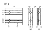
- Fig. 3 shows another example of an embodiment of a cooking plate 100 according to the present invention.
- the cooking plate 100 comprises spacers 310-370.
- the spacers 310-335 are oriented horizontally thereby allowing easy movement of cooking pots e.g. between cooking areas 385 and 380.
- the spacers in form of bands 340-370 covering plural cooking areas 390 and 395 allow easy movement of cooking vessels in the vertical direction and also provide support for cooking vessels with a large bottom that extends e.g. over two cooking areas. In this manner, the invention can provide up to 4% energy savings as energy measurements show.
- Fig. 4 shows a cooking vessel 400 having a bottom/ spacer made of thermal insulating material in particular a material having a high thermal resistance to block energy flow from e.g. water boiled inside e.g. the kettle to the surface of an induction heater such as glass ceramic.
- the width of the bottom 410 is approximately 10 mm to provide optimum isolation while at the same time allowing full penetration of high frequency waves generated by the induction heater.
- the bottom/ spacer of the vessel 400 shown in Fig. 4 may form different kinds of spacers having different shapes.
- a complete layer of insulating material covers the bottom.
- bands of insulating spacers are arranged in parallel along the total area of the bottom of the cooking vessel 400.
- the number and distance of these bands of isolating spacers is only for illustrative purposes and a suitable number may be chosen that provides support for the cooking vessel and secures a certain distance to the cooking surface of the induction hob.
- the spacers may also take the shape of concentric circles, the number and distance of these circles is only chosen to illustrate the shape e.g.
Landscapes
- Physics & Mathematics (AREA)
- Electromagnetism (AREA)
- Cookers (AREA)
- Induction Heating Cooking Devices (AREA)
- Electric Stoves And Ranges (AREA)
Abstract
Description
- In modern households, cooking appliances in the form of electric ovens or gas ovens are almost present everywhere. In recent times, electric ovens are developing in the direction of induction powered cooking plates. This form of an electric heating mechanism has the advantage that it only heats the cooking vessel and thus has a low heat inertia.
- Power consumption concerns also become more important in households as electric energy becomes more and more expensive. As a consequence, home appliance manufacturers strive to develop home appliances that consume less energy. In some countries, such as Germany, energy grades have been established in order to give a potential customer an indication about the energy efficiency of the device he is intending to buy.
- In particular in the area of cooking devices, energy consumption is of predominant concern.
- Induction powered cooking plates are per se known in the art. The page shown under the URL
"http://www.smalltao.com/product/18269636015/Electrical%20Tecwor ld%20TIANHE%20TH-A207%20Cooker%20generation%20product%20special%20radiation-free%20high-frequency%20stove"
shows an induction heater with wedges on the top. It appears that these wedges serve to position a cooking vessel. One of the pictures to be found for further illustration of the product show the text "hot after use, do not touch". No other prior art is known. - The applicant has realized that at conventional induction heaters energy can be saved.
- It is an object of the present invention to provide a power saving cooking plate, a cooking vessel and an induction cooking arrangement.
- This object is solved by an induction cooking plate according to claim 1, an induction cooking vessel according to claim 13 and an induction cooking arrangement according to claim 15.
- Advantageous embodiments are given in the dependent claims.
- Advantageously, an induction cooking plate according to the present invention avoids that heat is transferred from a cooking good which is kept in a cooking vessel to a surface that supports an induction heating arrangement. In this manner, the thermal inertia is minimized and only the cooking vessel including the cooking goods is heated which minimizes the mass that needs to be heated and thus minimizes the power that is used for cooking.
- Beneficially, in a further development of a cooking plate according to the instant invention, an isolated material is embedded in a cooking surface in order to disrupt the thermal energy flow back from the cooking vessel into the cooking surface. At the same time, advantageously, a flat cooking surface can be maintained that allows moving cooking pots back and forth without obstacles.
- Favourably, according to a further development of an embodiment according to the present invention, spacers are provided to keep a cooking vessel in a distance to the inductive heater. In this manner, with a technically simple solution, the object of the invention can be solved and by using thermally isolating spacers, a maximum effect can be achieved.
- Favourably, according to a further development of an embodiment of the instant invention, plural spacers are provided. In this manner, the cooking plate can be individually adapted to the size of the shape of a cooking vessel.
- Beneficially, according to a further development of an embodiment of the present invention, the area occupied by the spacers is very small against the area of the cooking plate that usually conforms with the size of a cooking pot because in this manner, the thermal conduction back into the cooking surface can be minimized.
- Beneficially, according to a further development of an embodiment of the instant invention, a cooking surface of a cooking plate has build-in spacers in a form of e.g. a protrusion. In this manner, an easy to clean monolithic surface is maintained while at the same time being able to benefit from the power savings provided by the present invention.
- Favourably, according to a further development of an embodiment of the present invention, a curvature is provided in the cooking plate because curvatures are technically easy to manufacture, avoid steps in the surface and are easy to clean.
- Particularly beneficial is a further development of an embodiment of the present invention where the curvature protrudes at least 10 mm from a flat surface of a cooking plate because it then provides an optimum distance between the cooking vessel and the flat cooking surface in order to maximally avoid thermal conduction while at the same time providing optimum inductive heating efficiency.
- Beneficially, according to a further development of an embodiment of the present invention, a cooking plate comprises plural induction cooking areas. In this manner, the benefits of the instant invention can be provided for a household appliance and thus multiply the energy savings.
- Favourably, according to a further development of an embodiment of the present invention, spacers extend over plural inductive areas. In this manner, beneficially, larger cooking vessels can be used and benefit from the advantages of the present invention.
- Advantageously, according to a further development of an embodiment according to the present invention, the spacers are provided in form of bands that allow easy movement of a cooking vessel in the longitudinal direction of the bands.
- Favourably, in a further development of an embodiment according to the present invention, isolation material is made of heat resistive material such as glass ceramic. In this manner, maximum disruption of a thermal energy flow can be achieved.
- Advantageously, a cooking vessel according to an embodiment of the present invention has a bottom/spacer made of heat resistive material especially glass ceramic.
- Advantageously, in this manner, a spacer is provided and integral with the cooking vessel. Such a cooking vessel also provides a maximum of ease of use for an operator.
- Favourably, a cooking vessel according to an embodiment of the instant invention maybe respectively equipped with an isolation material of various shapes in order to be adapted to its daily use and to the technical requirements for such a cooking vessel, e.g. a cordless kettle.
- Beneficially, a cooking arrangement according to an embodiment of the present invention comprises an induction cooking plate, a spacer made from thermally resistant material and a cooking plate. In this manner, a simple technical arrangement in form of different layers is provided that has the merits of the power saving according to the instant invention.
- Further below, embodiments of the invention are discussed on a basis of examples shown in drawings wherein:
- Fig. 1
- shows a cooking plate;
- Fig. 2
- shows a section of an induction oven;
- Fig. 3
- shows two examples of a cooking surface having spacers;
- Fig. 4
- shows a cooking vessel in the form of a cordless kettle; and
- Fig. 5
- shows different shapes of spacers at the bottom of the cooking vessel shown in
Fig. 4 . - As
Fig. 1 shows, a cooking plate orhob 100 may consist of several individualinduction cooking areas 125. In this example, eachcooking area 125 is provided with spacers made from for example heat resistive material. The Applicant has found that spacers can save energy. The better the material prevents thermal conduction, the more efficient the cooking plate according to the present invention becomes. In this embodiment, spacers 110-120 are provided in the number of 3 having a circular shape. The shape of these spacers is only shown exemplarily and may take any other form that is suitable for the desired application. As long as the spacers allow the magnetic field from the induction heater to penetrate a metallic cooking vessel and prevent thermal energy to flow back into acooking surface 105. - As
Fig. 2 shows, an induction oven shown in thesection 200 may be provided withseparate cooking areas 210 having a border around them 125. In one embodiment, thecooking area 210 may be comprised of a layer of heat insulating material that is preferably made of thermally resistive material. In this manner, a totally flat surface of the hob can be provided that allows easy movement of pots from one cooking area to another. In one preferable embodiment, the border of thecooking area 210 may be formed of acurvature 125 that is 10 mm high and has a radius of preferably 2.5 mm and a width of 5 mm as indicated with 225 and 220 in thecross-section 215 ofFig. 2 . Of course, other dimensions can be conceived that however must satisfy the criteria that they keep a cooking pot at a certain distance to optimally insulate it from thecooking surface 220 while at the same time allowing high frequency energy to be transmitted into e.g. the bottom of the cooking pot. Preferably, the material of the cooking hob is glass ceramics. -
Fig. 3 shows another example of an embodiment of acooking plate 100 according to the present invention. Here, thecooking plate 100 comprises spacers 310-370. At the left of the square shaped cooking areas shown inFig. 3 , the spacers 310-335 are oriented horizontally thereby allowing easy movement of cooking pots e.g. betweencooking areas Fig. 3 , the spacers in form of bands 340-370 coveringplural cooking areas -
Fig. 4 shows acooking vessel 400 having a bottom/ spacer made of thermal insulating material in particular a material having a high thermal resistance to block energy flow from e.g. water boiled inside e.g. the kettle to the surface of an induction heater such as glass ceramic. The width of the bottom 410 is approximately 10 mm to provide optimum isolation while at the same time allowing full penetration of high frequency waves generated by the induction heater. - As
Fig. 5 shows, the bottom/ spacer of thevessel 400 shown inFig. 4 may form different kinds of spacers having different shapes. As indicated with 515, a complete layer of insulating material covers the bottom. On the other hand, marked by 520, bands of insulating spacers are arranged in parallel along the total area of the bottom of thecooking vessel 400. The number and distance of these bands of isolating spacers is only for illustrative purposes and a suitable number may be chosen that provides support for the cooking vessel and secures a certain distance to the cooking surface of the induction hob. As shown at 530 inFig. 5 , the spacers may also take the shape of concentric circles, the number and distance of these circles is only chosen to illustrate the shape e.g. only one circle may also be sufficient to support a kettle for boiling water on a cooking surface of an induction hob.List of reference numerals 100,200: induction cooking plate 105, 210 ,380,...,395: induction cooking area 110,..., 120; 310,..., 370; 220; 410: thermally isolating spacers 125: curvature 220: height of curvature 215: cross-section through induction cooking plate 225: width of curvature 400: cooking vessel 410: isolating bottom / spacer of cooking vessel 515,...,530: shape of spacers of bottom of cooking vessel
Claims (15)
- Induction cooking plate (100, 200) at least comprising:- an induction cooking area (105, 210, 380, ..., 395),- a thermal isolation (110-128, 220, 310-370) at an exterior surface of the cooking plate (100, 200).
- Cooking plate (100, 200) according to claim 1, wherein the thermal isolation is implemented in a layer of a thermally isolating material (210) embedded in a cooking surface (105)*.
- Induction cooking plate (100, 200) according to claim 1 comprising a spacer (110-120, 125, 310-380).
- Cooking plate (100, 200) according to claim 3 comprising plural individual spacers (110-120) per cooking area (105).
- Induction cooking plate (100, 200) according to claim 4, wherein the area covered by the spacers (110-120) is small against the cooking area (210).
- Induction cooking plate (100, 200) according to claim 3, wherein the spacer (125) is built into the cooking area (220).
- Induction cooking plate according to claim 6, where the spacer has the shape of a curvature (125) around a cooking area (220).
- Induction cooking plate (100, 200) according to claim 7, wherein the curvature has a height of 10 mm (220) and a width of 4 - 6 mm (225).
- Induction cooking plate (100, 200) according to any of the previous claims comprising plural cooking areas (105, 210, 380, ..., 395)*.
- Induction cooking plate (100, 200) according to claim 9 in combination with claims 4 or 5, wherein the spacer (310-370) covers plural cooking areas (105).
- Induction cooking plate (100, 200) according to claim 10, wherein the spacers are provided in form of at least two bands (310, 370).
- Induction cooking plate (100, 200) according to any of the claims 1 to 11, wherein the thermally isolation is provided in the form of thermal resistant material or glass ceramic.
- Induction cooking vessel (400) comprising a bottom/ spacer (410) of a thermal resistant material.
- Induction cooking vessel according to claim 13, wherein the thermal resistant material is shaped as a disk (515) or stripes (520) or circles (530).
- Induction cooking arrangement comprising a cooking area (105), a cooking vessel (400) and a thermally resistant spacer (410) between a cooking good and the cooking area (105).
Priority Applications (6)
| Application Number | Priority Date | Filing Date | Title |
|---|---|---|---|
| EP13174884.0A EP2822357B1 (en) | 2013-07-03 | 2013-07-03 | Power saving induction cooking plate, cooking vessel and induction cooking arrangement |
| PCT/EP2014/060817 WO2015000641A2 (en) | 2013-07-03 | 2014-05-26 | Power saving induction cooking plate, cooking vessel and induction cooking arrangement |
| BR112015032231-0A BR112015032231B1 (en) | 2013-07-03 | 2014-05-26 | INDUCTION COOKING HOB |
| CN201480035196.6A CN105325054B (en) | 2013-07-03 | 2014-05-26 | Electricity-saving induction cooking plates, cookware and induction cooking arrangements |
| AU2014286541A AU2014286541B2 (en) | 2013-07-03 | 2014-05-26 | Power saving induction cooking plate, cooking vessel and induction cooking arrangement |
| US14/899,432 US20160150596A1 (en) | 2013-07-03 | 2014-05-26 | Power saving induction cooking plate, cooking vessel and induction cooking arrangement |
Applications Claiming Priority (1)
| Application Number | Priority Date | Filing Date | Title |
|---|---|---|---|
| EP13174884.0A EP2822357B1 (en) | 2013-07-03 | 2013-07-03 | Power saving induction cooking plate, cooking vessel and induction cooking arrangement |
Publications (2)
| Publication Number | Publication Date |
|---|---|
| EP2822357A1 true EP2822357A1 (en) | 2015-01-07 |
| EP2822357B1 EP2822357B1 (en) | 2021-03-31 |
Family
ID=48703289
Family Applications (1)
| Application Number | Title | Priority Date | Filing Date |
|---|---|---|---|
| EP13174884.0A Active EP2822357B1 (en) | 2013-07-03 | 2013-07-03 | Power saving induction cooking plate, cooking vessel and induction cooking arrangement |
Country Status (6)
| Country | Link |
|---|---|
| US (1) | US20160150596A1 (en) |
| EP (1) | EP2822357B1 (en) |
| CN (1) | CN105325054B (en) |
| AU (1) | AU2014286541B2 (en) |
| BR (1) | BR112015032231B1 (en) |
| WO (1) | WO2015000641A2 (en) |
Families Citing this family (4)
| Publication number | Priority date | Publication date | Assignee | Title |
|---|---|---|---|---|
| ES2733979T3 (en) * | 2016-03-01 | 2019-12-03 | Adventys | Magnetic induction heating with spacer |
| ITUB20161251A1 (en) | 2016-03-02 | 2017-09-02 | Irca Spa | Induction hob and method for making induction hobs |
| KR102766398B1 (en) | 2019-09-10 | 2025-02-13 | 삼성전자주식회사 | Cooking apparatus |
| EP4255113B1 (en) * | 2021-03-29 | 2025-04-30 | Samsung Electronics Co., Ltd. | Cooking appliance |
Citations (4)
| Publication number | Priority date | Publication date | Assignee | Title |
|---|---|---|---|---|
| DE3602666A1 (en) * | 1986-01-29 | 1987-07-30 | Wmf Wuerttemberg Metallwaren | Appliance for cooking food |
| US6051821A (en) * | 1995-04-07 | 2000-04-18 | Aktiebolaget Electrolux | Cooking surface with optimized distance between induction coil and cooking vessel |
| JP2008166088A (en) * | 2006-12-28 | 2008-07-17 | Nippon Foil Mfg Co Ltd | Mat for electromagnetic induction heating stove |
| KR20100010593A (en) * | 2008-07-23 | 2010-02-02 | (주)지지엘 | Induction range having cheap style cooking plate |
Family Cites Families (13)
| Publication number | Priority date | Publication date | Assignee | Title |
|---|---|---|---|---|
| US3715550A (en) * | 1972-02-22 | 1973-02-06 | Gen Electric | Induction cooking/warming appliance including vessel supporting means having an undulant surface and temperature sensing means associated with said surface |
| GB1428555A (en) * | 1972-05-17 | 1976-03-17 | Mitsubishi Electric Corp | Induction heating apparatus |
| US3949183A (en) * | 1972-10-20 | 1976-04-06 | Mitsubishi Denki Kabushiki Kaisha | Cover plate for induction heating apparatus |
| FR2609533B1 (en) * | 1987-01-13 | 1990-05-25 | Cableco Sa | ELECTRIC INDUCTION HEATER |
| US5603858A (en) * | 1995-06-02 | 1997-02-18 | Aladdin Synergetics, Inc. | Heat retentive server for induction heating |
| US8766147B2 (en) * | 2008-05-20 | 2014-07-01 | Kenyon International, Inc. | Induction cook-top apparatus |
| TWI600348B (en) * | 2009-01-06 | 2017-09-21 | 通路實業集團國際公司 | Smart cookware |
| ES2356442B1 (en) * | 2009-01-13 | 2012-03-13 | Bsh Electrodomesticos España, S.A | COOKING FIELD WITH A COVER PLATE. |
| TW201036493A (en) * | 2009-03-20 | 2010-10-01 | Delta Electronics Inc | Electric device having electromagnetic component and method for manufactroing the same |
| CN102471142B (en) * | 2009-08-17 | 2016-02-24 | Bsh家用电器有限公司 | Have and hot plate dish with the heating of the induction type of the cover plate of metal coat |
| FR2952289B1 (en) * | 2009-11-06 | 2012-02-24 | Pillivuyt | CERAMIC COOKING USTENSILE |
| KR101174051B1 (en) * | 2011-06-29 | 2012-08-13 | (주)디포인덕션 | Induction range with function of improved durability |
| US9084504B2 (en) * | 2011-11-01 | 2015-07-21 | Kenyon International, Inc. | Vibrating cooking system |
-
2013
- 2013-07-03 EP EP13174884.0A patent/EP2822357B1/en active Active
-
2014
- 2014-05-26 AU AU2014286541A patent/AU2014286541B2/en active Active
- 2014-05-26 BR BR112015032231-0A patent/BR112015032231B1/en active IP Right Grant
- 2014-05-26 US US14/899,432 patent/US20160150596A1/en not_active Abandoned
- 2014-05-26 CN CN201480035196.6A patent/CN105325054B/en active Active
- 2014-05-26 WO PCT/EP2014/060817 patent/WO2015000641A2/en not_active Ceased
Patent Citations (4)
| Publication number | Priority date | Publication date | Assignee | Title |
|---|---|---|---|---|
| DE3602666A1 (en) * | 1986-01-29 | 1987-07-30 | Wmf Wuerttemberg Metallwaren | Appliance for cooking food |
| US6051821A (en) * | 1995-04-07 | 2000-04-18 | Aktiebolaget Electrolux | Cooking surface with optimized distance between induction coil and cooking vessel |
| JP2008166088A (en) * | 2006-12-28 | 2008-07-17 | Nippon Foil Mfg Co Ltd | Mat for electromagnetic induction heating stove |
| KR20100010593A (en) * | 2008-07-23 | 2010-02-02 | (주)지지엘 | Induction range having cheap style cooking plate |
Also Published As
| Publication number | Publication date |
|---|---|
| AU2014286541B2 (en) | 2018-01-04 |
| US20160150596A1 (en) | 2016-05-26 |
| CN105325054A (en) | 2016-02-10 |
| EP2822357B1 (en) | 2021-03-31 |
| CN105325054B (en) | 2019-09-13 |
| BR112015032231B1 (en) | 2022-02-15 |
| BR112015032231A2 (en) | 2017-07-25 |
| WO2015000641A3 (en) | 2015-05-28 |
| WO2015000641A2 (en) | 2015-01-08 |
| AU2014286541A1 (en) | 2015-12-24 |
Similar Documents
| Publication | Publication Date | Title |
|---|---|---|
| US20100193502A1 (en) | Electric heater | |
| AU2014286541B2 (en) | Power saving induction cooking plate, cooking vessel and induction cooking arrangement | |
| US10798786B2 (en) | Cooking appliance with a cooking plate and with a heating device thereunder | |
| JP5404917B2 (en) | Induction heating tableware to keep dishes warm | |
| CN103479213B (en) | A kind of energy-conservation many pots of cooking pots | |
| JP3195027U (en) | Hot water type food warmer | |
| CN203723877U (en) | Energy-saving electric heating pot | |
| CN107669149A (en) | an oven | |
| KR20170071222A (en) | Electric cooker with plate heater | |
| CN201318709Y (en) | Cooking stove | |
| KR101174051B1 (en) | Induction range with function of improved durability | |
| CN204665396U (en) | A kind of heater with insulation effect | |
| CN204363726U (en) | steam/electromagnetic heating frying pan | |
| CN103371717A (en) | Electric cooker | |
| CN203970068U (en) | A kind of double-layer electric pottery stove | |
| KR20180119043A (en) | Electric cooker combined with warmer | |
| CN107305025A (en) | A kind of Far-infrared Heating disk and far infrared cooking equipment | |
| CN201664220U (en) | Novel roasting pan | |
| CN105832130B (en) | steam/electromagnetic heating frying pan | |
| CN103505066A (en) | Pizza baking rack | |
| CN108851934A (en) | A kind of infrared ray electromagnetism composite heating cookware | |
| CN209463860U (en) | A kind of full glass roasting plate of electromagnetic heating | |
| EP2615378B1 (en) | Griddle plate | |
| CN101813328A (en) | Electric heating furnace and oven with same | |
| CN205174471U (en) | Electric ceramic stove |
Legal Events
| Date | Code | Title | Description |
|---|---|---|---|
| PUAI | Public reference made under article 153(3) epc to a published international application that has entered the european phase |
Free format text: ORIGINAL CODE: 0009012 |
|
| 17P | Request for examination filed |
Effective date: 20130703 |
|
| AK | Designated contracting states |
Kind code of ref document: A1 Designated state(s): AL AT BE BG CH CY CZ DE DK EE ES FI FR GB GR HR HU IE IS IT LI LT LU LV MC MK MT NL NO PL PT RO RS SE SI SK SM TR |
|
| AX | Request for extension of the european patent |
Extension state: BA ME |
|
| R17P | Request for examination filed (corrected) |
Effective date: 20150128 |
|
| RBV | Designated contracting states (corrected) |
Designated state(s): AL AT BE BG CH CY CZ DE DK EE ES FI FR GB GR HR HU IE IS IT LI LT LU LV MC MK MT NL NO PL PT RO RS SE SI SK SM TR |
|
| STAA | Information on the status of an ep patent application or granted ep patent |
Free format text: STATUS: EXAMINATION IS IN PROGRESS |
|
| 17Q | First examination report despatched |
Effective date: 20180523 |
|
| GRAP | Despatch of communication of intention to grant a patent |
Free format text: ORIGINAL CODE: EPIDOSNIGR1 |
|
| STAA | Information on the status of an ep patent application or granted ep patent |
Free format text: STATUS: GRANT OF PATENT IS INTENDED |
|
| INTG | Intention to grant announced |
Effective date: 20201106 |
|
| GRAS | Grant fee paid |
Free format text: ORIGINAL CODE: EPIDOSNIGR3 |
|
| GRAA | (expected) grant |
Free format text: ORIGINAL CODE: 0009210 |
|
| STAA | Information on the status of an ep patent application or granted ep patent |
Free format text: STATUS: THE PATENT HAS BEEN GRANTED |
|
| AK | Designated contracting states |
Kind code of ref document: B1 Designated state(s): AL AT BE BG CH CY CZ DE DK EE ES FI FR GB GR HR HU IE IS IT LI LT LU LV MC MK MT NL NO PL PT RO RS SE SI SK SM TR |
|
| REG | Reference to a national code |
Ref country code: GB Ref legal event code: FG4D Ref country code: CH Ref legal event code: EP |
|
| REG | Reference to a national code |
Ref country code: AT Ref legal event code: REF Ref document number: 1378439 Country of ref document: AT Kind code of ref document: T Effective date: 20210415 |
|
| REG | Reference to a national code |
Ref country code: DE Ref legal event code: R096 Ref document number: 602013076540 Country of ref document: DE |
|
| REG | Reference to a national code |
Ref country code: IE Ref legal event code: FG4D |
|
| REG | Reference to a national code |
Ref country code: LT Ref legal event code: MG9D |
|
| PG25 | Lapsed in a contracting state [announced via postgrant information from national office to epo] |
Ref country code: NO Free format text: LAPSE BECAUSE OF FAILURE TO SUBMIT A TRANSLATION OF THE DESCRIPTION OR TO PAY THE FEE WITHIN THE PRESCRIBED TIME-LIMIT Effective date: 20210630 Ref country code: BG Free format text: LAPSE BECAUSE OF FAILURE TO SUBMIT A TRANSLATION OF THE DESCRIPTION OR TO PAY THE FEE WITHIN THE PRESCRIBED TIME-LIMIT Effective date: 20210630 Ref country code: HR Free format text: LAPSE BECAUSE OF FAILURE TO SUBMIT A TRANSLATION OF THE DESCRIPTION OR TO PAY THE FEE WITHIN THE PRESCRIBED TIME-LIMIT Effective date: 20210331 Ref country code: FI Free format text: LAPSE BECAUSE OF FAILURE TO SUBMIT A TRANSLATION OF THE DESCRIPTION OR TO PAY THE FEE WITHIN THE PRESCRIBED TIME-LIMIT Effective date: 20210331 |
|
| PG25 | Lapsed in a contracting state [announced via postgrant information from national office to epo] |
Ref country code: SE Free format text: LAPSE BECAUSE OF FAILURE TO SUBMIT A TRANSLATION OF THE DESCRIPTION OR TO PAY THE FEE WITHIN THE PRESCRIBED TIME-LIMIT Effective date: 20210331 Ref country code: LV Free format text: LAPSE BECAUSE OF FAILURE TO SUBMIT A TRANSLATION OF THE DESCRIPTION OR TO PAY THE FEE WITHIN THE PRESCRIBED TIME-LIMIT Effective date: 20210331 Ref country code: RS Free format text: LAPSE BECAUSE OF FAILURE TO SUBMIT A TRANSLATION OF THE DESCRIPTION OR TO PAY THE FEE WITHIN THE PRESCRIBED TIME-LIMIT Effective date: 20210331 |
|
| REG | Reference to a national code |
Ref country code: NL Ref legal event code: MP Effective date: 20210331 |
|
| REG | Reference to a national code |
Ref country code: AT Ref legal event code: MK05 Ref document number: 1378439 Country of ref document: AT Kind code of ref document: T Effective date: 20210331 |
|
| PG25 | Lapsed in a contracting state [announced via postgrant information from national office to epo] |
Ref country code: AT Free format text: LAPSE BECAUSE OF FAILURE TO SUBMIT A TRANSLATION OF THE DESCRIPTION OR TO PAY THE FEE WITHIN THE PRESCRIBED TIME-LIMIT Effective date: 20210331 Ref country code: SM Free format text: LAPSE BECAUSE OF FAILURE TO SUBMIT A TRANSLATION OF THE DESCRIPTION OR TO PAY THE FEE WITHIN THE PRESCRIBED TIME-LIMIT Effective date: 20210331 Ref country code: NL Free format text: LAPSE BECAUSE OF FAILURE TO SUBMIT A TRANSLATION OF THE DESCRIPTION OR TO PAY THE FEE WITHIN THE PRESCRIBED TIME-LIMIT Effective date: 20210331 Ref country code: LT Free format text: LAPSE BECAUSE OF FAILURE TO SUBMIT A TRANSLATION OF THE DESCRIPTION OR TO PAY THE FEE WITHIN THE PRESCRIBED TIME-LIMIT Effective date: 20210331 Ref country code: CZ Free format text: LAPSE BECAUSE OF FAILURE TO SUBMIT A TRANSLATION OF THE DESCRIPTION OR TO PAY THE FEE WITHIN THE PRESCRIBED TIME-LIMIT Effective date: 20210331 Ref country code: EE Free format text: LAPSE BECAUSE OF FAILURE TO SUBMIT A TRANSLATION OF THE DESCRIPTION OR TO PAY THE FEE WITHIN THE PRESCRIBED TIME-LIMIT Effective date: 20210331 |
|
| PG25 | Lapsed in a contracting state [announced via postgrant information from national office to epo] |
Ref country code: PL Free format text: LAPSE BECAUSE OF FAILURE TO SUBMIT A TRANSLATION OF THE DESCRIPTION OR TO PAY THE FEE WITHIN THE PRESCRIBED TIME-LIMIT Effective date: 20210331 Ref country code: PT Free format text: LAPSE BECAUSE OF FAILURE TO SUBMIT A TRANSLATION OF THE DESCRIPTION OR TO PAY THE FEE WITHIN THE PRESCRIBED TIME-LIMIT Effective date: 20210802 Ref country code: ES Free format text: LAPSE BECAUSE OF FAILURE TO SUBMIT A TRANSLATION OF THE DESCRIPTION OR TO PAY THE FEE WITHIN THE PRESCRIBED TIME-LIMIT Effective date: 20210331 Ref country code: SK Free format text: LAPSE BECAUSE OF FAILURE TO SUBMIT A TRANSLATION OF THE DESCRIPTION OR TO PAY THE FEE WITHIN THE PRESCRIBED TIME-LIMIT Effective date: 20210331 Ref country code: IS Free format text: LAPSE BECAUSE OF FAILURE TO SUBMIT A TRANSLATION OF THE DESCRIPTION OR TO PAY THE FEE WITHIN THE PRESCRIBED TIME-LIMIT Effective date: 20210731 Ref country code: RO Free format text: LAPSE BECAUSE OF FAILURE TO SUBMIT A TRANSLATION OF THE DESCRIPTION OR TO PAY THE FEE WITHIN THE PRESCRIBED TIME-LIMIT Effective date: 20210331 |
|
| REG | Reference to a national code |
Ref country code: DE Ref legal event code: R097 Ref document number: 602013076540 Country of ref document: DE |
|
| PG25 | Lapsed in a contracting state [announced via postgrant information from national office to epo] |
Ref country code: DK Free format text: LAPSE BECAUSE OF FAILURE TO SUBMIT A TRANSLATION OF THE DESCRIPTION OR TO PAY THE FEE WITHIN THE PRESCRIBED TIME-LIMIT Effective date: 20210331 Ref country code: AL Free format text: LAPSE BECAUSE OF FAILURE TO SUBMIT A TRANSLATION OF THE DESCRIPTION OR TO PAY THE FEE WITHIN THE PRESCRIBED TIME-LIMIT Effective date: 20210331 |
|
| PLBE | No opposition filed within time limit |
Free format text: ORIGINAL CODE: 0009261 |
|
| STAA | Information on the status of an ep patent application or granted ep patent |
Free format text: STATUS: NO OPPOSITION FILED WITHIN TIME LIMIT |
|
| REG | Reference to a national code |
Ref country code: CH Ref legal event code: PL |
|
| 26N | No opposition filed |
Effective date: 20220104 |
|
| GBPC | Gb: european patent ceased through non-payment of renewal fee |
Effective date: 20210703 |
|
| PG25 | Lapsed in a contracting state [announced via postgrant information from national office to epo] |
Ref country code: MC Free format text: LAPSE BECAUSE OF FAILURE TO SUBMIT A TRANSLATION OF THE DESCRIPTION OR TO PAY THE FEE WITHIN THE PRESCRIBED TIME-LIMIT Effective date: 20210331 |
|
| REG | Reference to a national code |
Ref country code: BE Ref legal event code: MM Effective date: 20210731 |
|
| PG25 | Lapsed in a contracting state [announced via postgrant information from national office to epo] |
Ref country code: LI Free format text: LAPSE BECAUSE OF NON-PAYMENT OF DUE FEES Effective date: 20210731 Ref country code: GB Free format text: LAPSE BECAUSE OF NON-PAYMENT OF DUE FEES Effective date: 20210703 Ref country code: CH Free format text: LAPSE BECAUSE OF NON-PAYMENT OF DUE FEES Effective date: 20210731 |
|
| PG25 | Lapsed in a contracting state [announced via postgrant information from national office to epo] |
Ref country code: IS Free format text: LAPSE BECAUSE OF FAILURE TO SUBMIT A TRANSLATION OF THE DESCRIPTION OR TO PAY THE FEE WITHIN THE PRESCRIBED TIME-LIMIT Effective date: 20210731 Ref country code: LU Free format text: LAPSE BECAUSE OF NON-PAYMENT OF DUE FEES Effective date: 20210703 |
|
| PG25 | Lapsed in a contracting state [announced via postgrant information from national office to epo] |
Ref country code: IE Free format text: LAPSE BECAUSE OF NON-PAYMENT OF DUE FEES Effective date: 20210703 Ref country code: BE Free format text: LAPSE BECAUSE OF NON-PAYMENT OF DUE FEES Effective date: 20210731 |
|
| PGFP | Annual fee paid to national office [announced via postgrant information from national office to epo] |
Ref country code: IT Payment date: 20220726 Year of fee payment: 10 Ref country code: DE Payment date: 20220720 Year of fee payment: 10 |
|
| PGFP | Annual fee paid to national office [announced via postgrant information from national office to epo] |
Ref country code: FR Payment date: 20220720 Year of fee payment: 10 |
|
| PG25 | Lapsed in a contracting state [announced via postgrant information from national office to epo] |
Ref country code: HU Free format text: LAPSE BECAUSE OF FAILURE TO SUBMIT A TRANSLATION OF THE DESCRIPTION OR TO PAY THE FEE WITHIN THE PRESCRIBED TIME-LIMIT; INVALID AB INITIO Effective date: 20130703 |
|
| PG25 | Lapsed in a contracting state [announced via postgrant information from national office to epo] |
Ref country code: CY Free format text: LAPSE BECAUSE OF FAILURE TO SUBMIT A TRANSLATION OF THE DESCRIPTION OR TO PAY THE FEE WITHIN THE PRESCRIBED TIME-LIMIT Effective date: 20210331 |
|
| PG25 | Lapsed in a contracting state [announced via postgrant information from national office to epo] |
Ref country code: GR Free format text: LAPSE BECAUSE OF FAILURE TO SUBMIT A TRANSLATION OF THE DESCRIPTION OR TO PAY THE FEE WITHIN THE PRESCRIBED TIME-LIMIT Effective date: 20210331 |
|
| P01 | Opt-out of the competence of the unified patent court (upc) registered |
Effective date: 20230625 |
|
| REG | Reference to a national code |
Ref country code: DE Ref legal event code: R119 Ref document number: 602013076540 Country of ref document: DE |
|
| PG25 | Lapsed in a contracting state [announced via postgrant information from national office to epo] |
Ref country code: MK Free format text: LAPSE BECAUSE OF FAILURE TO SUBMIT A TRANSLATION OF THE DESCRIPTION OR TO PAY THE FEE WITHIN THE PRESCRIBED TIME-LIMIT Effective date: 20210331 Ref country code: DE Free format text: LAPSE BECAUSE OF NON-PAYMENT OF DUE FEES Effective date: 20240201 |
|
| PG25 | Lapsed in a contracting state [announced via postgrant information from national office to epo] |
Ref country code: FR Free format text: LAPSE BECAUSE OF NON-PAYMENT OF DUE FEES Effective date: 20230731 |
|
| PG25 | Lapsed in a contracting state [announced via postgrant information from national office to epo] |
Ref country code: TR Free format text: LAPSE BECAUSE OF FAILURE TO SUBMIT A TRANSLATION OF THE DESCRIPTION OR TO PAY THE FEE WITHIN THE PRESCRIBED TIME-LIMIT Effective date: 20210331 |
|
| PG25 | Lapsed in a contracting state [announced via postgrant information from national office to epo] |
Ref country code: IT Free format text: LAPSE BECAUSE OF NON-PAYMENT OF DUE FEES Effective date: 20230703 |
|
| PG25 | Lapsed in a contracting state [announced via postgrant information from national office to epo] |
Ref country code: MT Free format text: LAPSE BECAUSE OF FAILURE TO SUBMIT A TRANSLATION OF THE DESCRIPTION OR TO PAY THE FEE WITHIN THE PRESCRIBED TIME-LIMIT Effective date: 20210331 |