EP2822134A1 - Dispositif de gestion énergétique d'un dispositif de pompe à chaleur - Google Patents
Dispositif de gestion énergétique d'un dispositif de pompe à chaleur Download PDFInfo
- Publication number
- EP2822134A1 EP2822134A1 EP13754639.6A EP13754639A EP2822134A1 EP 2822134 A1 EP2822134 A1 EP 2822134A1 EP 13754639 A EP13754639 A EP 13754639A EP 2822134 A1 EP2822134 A1 EP 2822134A1
- Authority
- EP
- European Patent Office
- Prior art keywords
- heat pump
- consumption
- management device
- unit
- energy
- Prior art date
- Legal status (The legal status is an assumption and is not a legal conclusion. Google has not performed a legal analysis and makes no representation as to the accuracy of the status listed.)
- Ceased
Links
- 238000005265 energy consumption Methods 0.000 claims abstract description 113
- 230000004044 response Effects 0.000 claims abstract description 61
- 238000013178 mathematical model Methods 0.000 claims description 7
- XLYOFNOQVPJJNP-UHFFFAOYSA-N water Substances O XLYOFNOQVPJJNP-UHFFFAOYSA-N 0.000 description 54
- 238000004891 communication Methods 0.000 description 24
- 230000006870 function Effects 0.000 description 12
- 238000010438 heat treatment Methods 0.000 description 11
- 238000010586 diagram Methods 0.000 description 8
- 238000010801 machine learning Methods 0.000 description 4
- 230000004048 modification Effects 0.000 description 4
- 238000012986 modification Methods 0.000 description 4
- 239000003507 refrigerant Substances 0.000 description 3
- 239000000284 extract Substances 0.000 description 2
- 239000004973 liquid crystal related substance Substances 0.000 description 2
- 238000000034 method Methods 0.000 description 2
- 230000006641 stabilisation Effects 0.000 description 2
- 238000011105 stabilization Methods 0.000 description 2
- 230000001174 ascending effect Effects 0.000 description 1
- 239000000872 buffer Substances 0.000 description 1
- 230000000694 effects Effects 0.000 description 1
- 230000005611 electricity Effects 0.000 description 1
- 238000010248 power generation Methods 0.000 description 1
- 238000000513 principal component analysis Methods 0.000 description 1
- 238000000611 regression analysis Methods 0.000 description 1
- 230000000717 retained effect Effects 0.000 description 1
- 239000008399 tap water Substances 0.000 description 1
- 235000020679 tap water Nutrition 0.000 description 1
Images


Classifications
-
- G—PHYSICS
- G05—CONTROLLING; REGULATING
- G05F—SYSTEMS FOR REGULATING ELECTRIC OR MAGNETIC VARIABLES
- G05F1/00—Automatic systems in which deviations of an electric quantity from one or more predetermined values are detected at the output of the system and fed back to a device within the system to restore the detected quantity to its predetermined value or values, i.e. retroactive systems
- G05F1/66—Regulating electric power
-
- F—MECHANICAL ENGINEERING; LIGHTING; HEATING; WEAPONS; BLASTING
- F25—REFRIGERATION OR COOLING; COMBINED HEATING AND REFRIGERATION SYSTEMS; HEAT PUMP SYSTEMS; MANUFACTURE OR STORAGE OF ICE; LIQUEFACTION SOLIDIFICATION OF GASES
- F25B—REFRIGERATION MACHINES, PLANTS OR SYSTEMS; COMBINED HEATING AND REFRIGERATION SYSTEMS; HEAT PUMP SYSTEMS
- F25B30/00—Heat pumps
-
- F—MECHANICAL ENGINEERING; LIGHTING; HEATING; WEAPONS; BLASTING
- F25—REFRIGERATION OR COOLING; COMBINED HEATING AND REFRIGERATION SYSTEMS; HEAT PUMP SYSTEMS; MANUFACTURE OR STORAGE OF ICE; LIQUEFACTION SOLIDIFICATION OF GASES
- F25B—REFRIGERATION MACHINES, PLANTS OR SYSTEMS; COMBINED HEATING AND REFRIGERATION SYSTEMS; HEAT PUMP SYSTEMS
- F25B49/00—Arrangement or mounting of control or safety devices
-
- G—PHYSICS
- G05—CONTROLLING; REGULATING
- G05B—CONTROL OR REGULATING SYSTEMS IN GENERAL; FUNCTIONAL ELEMENTS OF SUCH SYSTEMS; MONITORING OR TESTING ARRANGEMENTS FOR SUCH SYSTEMS OR ELEMENTS
- G05B13/00—Adaptive control systems, i.e. systems automatically adjusting themselves to have a performance which is optimum according to some preassigned criterion
- G05B13/02—Adaptive control systems, i.e. systems automatically adjusting themselves to have a performance which is optimum according to some preassigned criterion electric
- G05B13/0265—Adaptive control systems, i.e. systems automatically adjusting themselves to have a performance which is optimum according to some preassigned criterion electric the criterion being a learning criterion
-
- G—PHYSICS
- G06—COMPUTING; CALCULATING OR COUNTING
- G06N—COMPUTING ARRANGEMENTS BASED ON SPECIFIC COMPUTATIONAL MODELS
- G06N20/00—Machine learning
-
- G—PHYSICS
- G06—COMPUTING; CALCULATING OR COUNTING
- G06Q—INFORMATION AND COMMUNICATION TECHNOLOGY [ICT] SPECIALLY ADAPTED FOR ADMINISTRATIVE, COMMERCIAL, FINANCIAL, MANAGERIAL OR SUPERVISORY PURPOSES; SYSTEMS OR METHODS SPECIALLY ADAPTED FOR ADMINISTRATIVE, COMMERCIAL, FINANCIAL, MANAGERIAL OR SUPERVISORY PURPOSES, NOT OTHERWISE PROVIDED FOR
- G06Q10/00—Administration; Management
- G06Q10/06—Resources, workflows, human or project management; Enterprise or organisation planning; Enterprise or organisation modelling
-
- G—PHYSICS
- G06—COMPUTING; CALCULATING OR COUNTING
- G06Q—INFORMATION AND COMMUNICATION TECHNOLOGY [ICT] SPECIALLY ADAPTED FOR ADMINISTRATIVE, COMMERCIAL, FINANCIAL, MANAGERIAL OR SUPERVISORY PURPOSES; SYSTEMS OR METHODS SPECIALLY ADAPTED FOR ADMINISTRATIVE, COMMERCIAL, FINANCIAL, MANAGERIAL OR SUPERVISORY PURPOSES, NOT OTHERWISE PROVIDED FOR
- G06Q50/00—Information and communication technology [ICT] specially adapted for implementation of business processes of specific business sectors, e.g. utilities or tourism
- G06Q50/06—Energy or water supply
-
- F—MECHANICAL ENGINEERING; LIGHTING; HEATING; WEAPONS; BLASTING
- F25—REFRIGERATION OR COOLING; COMBINED HEATING AND REFRIGERATION SYSTEMS; HEAT PUMP SYSTEMS; MANUFACTURE OR STORAGE OF ICE; LIQUEFACTION SOLIDIFICATION OF GASES
- F25B—REFRIGERATION MACHINES, PLANTS OR SYSTEMS; COMBINED HEATING AND REFRIGERATION SYSTEMS; HEAT PUMP SYSTEMS
- F25B2600/00—Control issues
-
- H—ELECTRICITY
- H02—GENERATION; CONVERSION OR DISTRIBUTION OF ELECTRIC POWER
- H02J—CIRCUIT ARRANGEMENTS OR SYSTEMS FOR SUPPLYING OR DISTRIBUTING ELECTRIC POWER; SYSTEMS FOR STORING ELECTRIC ENERGY
- H02J2310/00—The network for supplying or distributing electric power characterised by its spatial reach or by the load
- H02J2310/10—The network having a local or delimited stationary reach
- H02J2310/12—The local stationary network supplying a household or a building
- H02J2310/14—The load or loads being home appliances
-
- H—ELECTRICITY
- H02—GENERATION; CONVERSION OR DISTRIBUTION OF ELECTRIC POWER
- H02J—CIRCUIT ARRANGEMENTS OR SYSTEMS FOR SUPPLYING OR DISTRIBUTING ELECTRIC POWER; SYSTEMS FOR STORING ELECTRIC ENERGY
- H02J3/00—Circuit arrangements for AC mains or AC distribution networks
- H02J3/12—Circuit arrangements for AC mains or AC distribution networks for adjusting voltage in AC networks by changing a characteristic of the network load
- H02J3/14—Circuit arrangements for AC mains or AC distribution networks for adjusting voltage in AC networks by changing a characteristic of the network load by switching loads on to, or off from, network, e.g. progressively balanced loading
-
- Y—GENERAL TAGGING OF NEW TECHNOLOGICAL DEVELOPMENTS; GENERAL TAGGING OF CROSS-SECTIONAL TECHNOLOGIES SPANNING OVER SEVERAL SECTIONS OF THE IPC; TECHNICAL SUBJECTS COVERED BY FORMER USPC CROSS-REFERENCE ART COLLECTIONS [XRACs] AND DIGESTS
- Y02—TECHNOLOGIES OR APPLICATIONS FOR MITIGATION OR ADAPTATION AGAINST CLIMATE CHANGE
- Y02B—CLIMATE CHANGE MITIGATION TECHNOLOGIES RELATED TO BUILDINGS, e.g. HOUSING, HOUSE APPLIANCES OR RELATED END-USER APPLICATIONS
- Y02B70/00—Technologies for an efficient end-user side electric power management and consumption
- Y02B70/30—Systems integrating technologies related to power network operation and communication or information technologies for improving the carbon footprint of the management of residential or tertiary loads, i.e. smart grids as climate change mitigation technology in the buildings sector, including also the last stages of power distribution and the control, monitoring or operating management systems at local level
- Y02B70/3225—Demand response systems, e.g. load shedding, peak shaving
-
- Y—GENERAL TAGGING OF NEW TECHNOLOGICAL DEVELOPMENTS; GENERAL TAGGING OF CROSS-SECTIONAL TECHNOLOGIES SPANNING OVER SEVERAL SECTIONS OF THE IPC; TECHNICAL SUBJECTS COVERED BY FORMER USPC CROSS-REFERENCE ART COLLECTIONS [XRACs] AND DIGESTS
- Y04—INFORMATION OR COMMUNICATION TECHNOLOGIES HAVING AN IMPACT ON OTHER TECHNOLOGY AREAS
- Y04S—SYSTEMS INTEGRATING TECHNOLOGIES RELATED TO POWER NETWORK OPERATION, COMMUNICATION OR INFORMATION TECHNOLOGIES FOR IMPROVING THE ELECTRICAL POWER GENERATION, TRANSMISSION, DISTRIBUTION, MANAGEMENT OR USAGE, i.e. SMART GRIDS
- Y04S20/00—Management or operation of end-user stationary applications or the last stages of power distribution; Controlling, monitoring or operating thereof
- Y04S20/20—End-user application control systems
- Y04S20/222—Demand response systems, e.g. load shedding, peak shaving
-
- Y—GENERAL TAGGING OF NEW TECHNOLOGICAL DEVELOPMENTS; GENERAL TAGGING OF CROSS-SECTIONAL TECHNOLOGIES SPANNING OVER SEVERAL SECTIONS OF THE IPC; TECHNICAL SUBJECTS COVERED BY FORMER USPC CROSS-REFERENCE ART COLLECTIONS [XRACs] AND DIGESTS
- Y04—INFORMATION OR COMMUNICATION TECHNOLOGIES HAVING AN IMPACT ON OTHER TECHNOLOGY AREAS
- Y04S—SYSTEMS INTEGRATING TECHNOLOGIES RELATED TO POWER NETWORK OPERATION, COMMUNICATION OR INFORMATION TECHNOLOGIES FOR IMPROVING THE ELECTRICAL POWER GENERATION, TRANSMISSION, DISTRIBUTION, MANAGEMENT OR USAGE, i.e. SMART GRIDS
- Y04S20/00—Management or operation of end-user stationary applications or the last stages of power distribution; Controlling, monitoring or operating thereof
- Y04S20/20—End-user application control systems
- Y04S20/242—Home appliances
- Y04S20/244—Home appliances the home appliances being or involving heating ventilating and air conditioning [HVAC] units
Definitions
- the present invention relates to a heat pump system energy management device.
- the electric power system stabilization system described in patent document 1 illustrates compressors of vending machines, river drainage pumps, or agricultural water pumps as the specific loads whose power consumption is to be controlled.
- stable supply and demand adjustments cannot be realized unless these loads adjust their power consumption as supposed.
- seasons in which supply and demand balance of power is tightened, such as in summer and winter it is important to adjust the power consumed by heat pump systems that many consumers have.
- a management device pertaining to a first aspect of the present invention is a management device that manages plural heat pump systems and brings a total amount of energy consumed by the heat pump systems closer to a target value.
- the management device comprises a request transmitting unit, a consumption information receiving unit, a database, and a learning unit.
- the request transmitting unit transmits requested values of energy consumption to each of the heat pump systems.
- the consumption information receiving unit receives actual values of energy consumption from each of the heat pump systems.
- the database stores response characteristics of consumers having each of the heat pump systems with respect to the requested values of energy consumption.
- the learning unit learns the response characteristics and reflects learning results based on past records of responses of each of the consumers with respect to the requested values of energy consumption in the database.
- the management device pertaining to the first aspect of the present invention can predict how each of the heat pump systems will respond to requests to adjust energy consumption. Because of this, stable supply and demand adjustments can be realized in a management device that manages the energy consumption of heat pump systems of plural consumers.
- the energy is, for example, electricity, and is expressed in units such as watts or watt-hours.
- a management device pertaining to a second aspect of the present invention is the management device pertaining to the first aspect, wherein the learning unit learns the response characteristics by connecting the actual values of energy consumption with information relating to at least one of season, day of week, time period, and weather.
- the management device pertaining to the second aspect uses the information such as season, day of week, time period, and weather and the past records as a base for learning the response characteristics. Because of this, highly reliable response characteristics can be obtained.
- a management device pertaining to a third aspect of the present invention is the management device pertaining to the first aspect or the second aspect, wherein the learning unit learns the response characteristics being mathematical models.
- the response characteristics are expressed as mathematical models. Because of this, highly reliably response characteristics can be obtained.
- a management device pertaining to a fourth aspect of the present invention is the management device pertaining to any of the first aspect to the third aspect, wherein the request transmitting unit transmits the requested values of energy consumption including information relating to incentives to each of the heat pump systems.
- the requested values of energy consumption include incentives. Because of this, each of the consumers can be offered incentives for following the requested values of energy consumption.
- a management device pertaining to a fifth aspect of the present invention is the management device pertaining to any of the first aspect to the fourth aspect and further comprises an energy consumption request receiving unit.
- the energy consumption request receiving unit receives the requested values of energy consumption or energy pricing information from a higher-level energy management device.
- the management device pertaining to the fifth aspect of the present invention obtains the requested values of energy consumption or the energy pricing information from the higher-level energy management device that an electric power company, for example, has. Because of this, the management device can fulfill the role of an aggregator which mediates between an electric power company and consumers for stable supply and demand adjustments of energy.
- a management device pertaining to a sixth aspect of the present invention is the management device pertaining to any of the first aspect to the fifth aspect and further comprises an allocating unit.
- the allocating unit allocates the requested values of energy consumption to each of the heat pump systems on the basis of the response characteristics.
- stable supply and demand adjustments can be realized by a management device that manages the energy consumption of heat pump systems of plural consumers.
- each of the consumers can be offered incentives for following the requested values of energy consumption.
- the management device pertaining to the fifth aspect of the present invention can fulfill the role of an aggregator which mediates between an electric power company and consumers for stable supply and demand adjustments of energy.
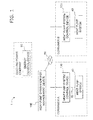
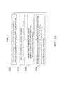
- FIG. 1 is a diagram schematically showing the configuration of an energy demand adjustment system 1 that includes a heat pump system energy management device 110 that is an example of the management device pertaining to the present invention.
- the energy demand adjustment system 1 mainly has an energy control device 90, the heat pump system energy management device 110, plural heat pump system control devices 100, and plural heat pump systems 40.
- the energy control device 90, the heat pump system energy management device 110, and the heat pump system control devices 100 are interconnected by a communication line, that is, a communication network 81 such as the Internet.
- the heat pump system control devices 100 are devices provided to the heat pump systems 40 and function as control units that control the heat pump systems 40.
- the energy control device 90 is a device that an electric power company has and is a higher-level (superordinate) energy management device to the heat pump system energy management device 110.
- the energy control device 90 collects information relating to energy supply and demand in order to perform adjustments so that energy demand and supply in the energy system of the electric power company are balanced.
- the energy control device 90 requests consumers to curb energy consumption.
- the energy control device 90 requests consumers to boost energy consumption.
- the energy control device 90 decides requests to the consumers regarding energy consumption as requested values of energy consumption by time period (e.g., every 1 minute).
- the energy control device 90 includes the requested values of energy consumption (the requested values in FIG. 7 ) in a total consumption request 123, which is data such as shown in FIG. 7 , and transmits the total consumption request 123 to the heat pump system energy management device 110.
- the heat pump system energy management device 110 is a management device that manages the plural heat pump systems 40 to bring the total amount of energy consumed by the plural heat pump systems 40 closer to the requested values in the total consumption request 123 that are target values.
- the heat pump system energy management device 110 is a server computer that a business operator called an aggregator has.
- the aggregator is a business operator who assembles plural consumers and mediates between the consumers and the electric power company for energy consumption adjustments on behalf of the consumers.
- the heat pump system energy management device 110 receives the total consumption request 123 from the energy control device 90 of the electric power company and decides, as requested values of energy consumption, amounts of energy by time period to be consumed by the heat pump systems 40 that each of the consumers has on the basis of the requested values of energy consumption by time period (e.g., every 1 minute) included in the total consumption request 123.
- the heat pump system energy management device 110 includes the requested values of energy consumption in individual consumption requests 124 and transmits the individual consumption requests 124 to each of the heat pump systems 40, that is, the heat pump system control devices 100.
- the individual consumption requests 124 are data including information relating to IDs (identification information) of each of the heat pump systems 40, requested values by time period, and monetary rewards or monetary penalties serving as incentives.
- the heat pump system energy management device 110 receives, from each of the heat pump system control devices 100, planned values of energy consumption by time period (e.g., every 1 minute) of each of the heat pump systems 40 and actual values of energy consumption by time period that each of the heat pump systems 40 has actually consumed.
- the heat pump system energy management device 110 tallies the planned values and the actual values of energy consumption of each of the heat pump systems 40, which the heat pump system energy management device 110 has received, and transmits the tallied values to the energy control device 90.
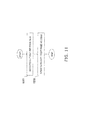
- FIG. 2 is a schematic configuration diagram of the heat pump system energy management device 110.
- the heat pump system energy management device 110 mainly has a communication unit 111, a control unit 112, and a storage unit 113.
- the communication unit 111 is an interface that makes the heat pump system energy management device 110 connectable to the communication network 81 using Ethernet (registered trademark; same below), for example.
- the storage unit 113 mainly comprises a RAM, a ROM, and a hard disk.
- a database 113a that accumulates and stores individual consumption plans 121, a total consumption plan 122, the individual consumption requests 124, the total consumption request 123, response characteristics 125, outside information 126, and operation data 103 a of each of the heat pump systems 40 is constructed.
- other kinds of information such as a program for the heat pump system energy management device 110, are also stored in the storage unit 113.
- the control unit 112 mainly comprises a CPU and executes the program for the heat pump system energy management device 110 stored in the storage unit 113.
- the control unit 112 mainly comprises a consumption information transmitting unit 112a, an energy consumption request receiving unit 112b, a consumption information receiving unit 112c, a tallying unit 112d, a request transmitting unit 112e, an allocating unit 112f, a learning unit 112g, and an outside information acquiring unit 112h by executing the program for the heat pump system energy management device 110.
- the consumption information transmitting unit 112a transmits to the higher-level energy control device 90 demand side provided information that is the planned values and the actual values of energy consumption by time period (e.g., every 1 minute) of the heat pump systems 40. Specifically, the demand side provided information is transmitted to the energy control device 90 as the total consumption plan 122 such as shown in FIG. 6 .
- the total consumption plan 122 is a plan in which the planned values and the actual values of energy consumption by time period (e.g., every 1 minute) of each of the heat pump systems 40, included in the individual consumption plans 121 such as shown in FIG. 5 , are tallied.
- the consumption information transmitting unit 112a transmits the total consumption plan 122 to the energy control device 90 via the communication unit 111, for example, once a day.
- the energy consumption request receiving unit 112b receives supply side provided information that is information relating to the requested values of energy consumption from the higher-level energy control device 90. Specifically, the supply side provided information is transmitted at predetermined intervals (e.g., 10 minutes) from the energy control device 90 as the total consumption request 123 such as shown in FIG 7 .
- the total consumption request 123 is data including the requested values of energy consumption (the requested values in FIG. 7 ) by time period (e.g., every 1 minute).
- the energy consumption request receiving unit 112b receives the total consumption request 123 via the communication unit 111 and stores it in the storage unit 113.
- the consumption information receiving unit 112c collects demand side provided information from the heat pump systems 40. Specifically, the demand side provided information is transmitted from each of the heat pump systems 40 as the individual consumption plan 121 such as shown in FIG. 5 .
- the individual consumption plans 121 are data including the IDs (identification information) of the heat pump systems 40 and the planned values and the actual values of energy consumption by time period (e.g., every 1 minute).
- the consumption information receiving unit 112c receives the later-described operation data 103a from each of the heat pump systems 40 via the communication unit 111.
- the consumption information receiving unit 112c receives the individual consumption plans 121 and the operation data 103 a from each of the heat pump systems 40 via the communication unit 111 at predetermined intervals (e.g., 3 hours) and accumulates the individual consumption plans 121 and the operation data 103a via a DBMS in the database 113a of the storage unit 113.
- the tallying unit 112d tallies the demand side provided information from each of the heat pump systems 40. Specifically, the tallying unit 112d tallies the individual consumption plans 121 stored in the storage unit 113 and stores the tallied results as the total consumption plan 122 in the database 113a.
- the request transmitting unit 112e transmits energy consumption requests (the individual consumption requests 124) that are requests relating to energy consumption to each of the heat pump systems 40 at predetermined intervals (e.g., 10 minutes) based on the total consumption request 123 that is the supply side provided information.
- the individual consumption requests 124 are data including the IDs (identification information) of each of the heat pump systems 40, requested values by time period, and monetary rewards or monetary penalties serving as incentives.
- the requested values are, as shown in FIG. 8 for example, information in which a percentage to the rated capacity of the heat pump system 40 is set as an upper limit or a lower limit.
- the monetary rewards or monetary penalties are rewards or penalties that the business operator operating the heat pump system energy management device 110 allocates to each of the heat pump systems 40 as incentives in accordance with the requested values on the basis of monetary amounts agreed in a contract between the electric power company and the business operator.
- the allocating unit 112f allocates energy consumption adjustment amounts and incentives to each of the heat pump systems 40. Specifically, the allocating unit 112f allocates energy consumption adjustment amounts to each of the heat pump systems 40 in such a way that the energy consumption amounts of all the heat pump systems 40 under management become the requested values of energy consumption (the requested values in FIG. 7 ) included in the total consumption request 123, and the allocating unit 112f stores the energy consumption adjustment amounts as the individual consumption requests 124 in the database 113a. Furthermore, the allocating unit 112f also allocates monetary rewards and monetary penalties as incentives for following the energy consumption adjustments to each of the heat pump systems 40 and includes the monetary rewards and monetary penalties in the individual consumption requests 124. The allocating unit 112f allocates the adjustment amounts and the incentives on the basis of the response characteristics 125 with respect to the requested values of energy consumption (the requested values in the individual consumption requests 124) of each of the heat pump systems 40. Allocation processing will be described in detail later.
- the learning unit 112g learns the response characteristics 125 and reflects the learning results based on past records of responses of each of the consumers to the requested values of energy consumption on the database 113a. Specifically, the learning unit 112g learns the response characteristics 125 by machine learning, for example, by connecting the actual values of energy consumption with information relating to at least one of season, day of week, time period, and weather.
- the response characteristics 125 are correlations between the actual values of the energy consumption adjustment amounts and the amounts of the monetary rewards or the amounts of the monetary penalties that are given as incentives.
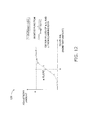
- the response characteristics 125 are mathematical models and are, for example, expressed as a sigmoid function having a curve such as shown in FIG. 12 .
- the outside information acquiring unit 112h acquires outside information that is information relating to weather, temperature, and humidity and so on by time period (e.g., every 1 minute).
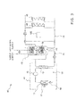
- FIG 3 is a diagram schematically showing the configuration of the heat pump systems 40.
- the heat pump systems 40 are room heating and hot water supplying systems and are capable of heating living spaces and supplying hot water.
- Each of the heat pump systems 40 is equipped with a heat pump unit 41, a hot water storage tank 42, a hot water supply pipe 43, a room heating circulation circuit 44, and the heat pump system control device 100.
- the heat pump unit 41 has a refrigerant circuit 16 and heats water sent from the hot water storage tank 42 and then turns the water into hot water.
- the refrigerant circuit 16 is mainly configured by sequentially connecting a compressor 12, a water heat exchanger 13 serving as a radiator, an electrically powered expansion valve 15 serving as an expansion mechanism, and an evaporator 11.
- the water heat exchanger 13 is a heat exchanger that functions as a refrigerant condenser.
- the hot water storage tank 42 stores the hot water that has been heated by the heat pump unit 41. Inside the hot water storage tank 42, plural sensors not shown in the drawings are juxtaposed vertically, and these sensors sense the temperature of the hot water inside the hot water storage tank and transmit temperature information to the heat pump system control device 100.
- the hot water storage tank 42 is connected to the heat pump unit 41 via a water heating circulation circuit 45.
- the water heating circulation circuit 45 allows the relatively low-temperature hot water in the lower portion of the hot water storage tank 42 to pass through the water heat exchanger 13 and returns the hot water to the hot water storage tank 42.
- the hot water supply pipe 43 branches from a water supply pipe, which supplies water, and incorporates into a hot water supply heat exchanger 32 disposed inside the hot water storage tank 42.
- the hot water supply pipe 43 is a pipe that allows tap water supplied from the water supply pipe to exchange heat with the hot water inside the hot water storage tank 42 at the hot water supply heat exchanger 32 and supplies hot water to a kitchen, bathtub, shower, and so forth at home.
- the room heating circulation circuit 44 circulates the hot water stored inside the hot water storage tank 42 by causing the hot water to pass through plural radiators 48 installed in living spaces in a building as room radiators that are one of heat utilizing means and then to return the hot water to the hot water storage tank 42 to thereby utilize the plural radiators 48 as heating appliances inside the living spaces.
- the heat pump system control device 100 controls the components of the heat pump system 40, such as the compressor 12. For example, when the temperature of the hot water inside the hot water storage tank 42 falls below a predetermined lower limit, the heat pump system control device 100 initiates a water heating operation and continues until the temperature of the hot water rises to a predetermined temperature. In the water heating operation, the heat pump system control device 100 causes the hot water inside the hot water storage tank 42 to flow to the heat pump unit 41 via the water heating circulation circuit 45, causes the hot water to pass through the water heat exchanger 13 to heat the hot water, and returns the hot water to the hot water storage tank 42. Furthermore, a control unit 47 controls the components of the heat pump system 40 on the basis of a later-described operation plan 103b.
- the operation plan 103b is input and set from a remote controller 130 by a user and is also created by the learning of the daily operation data 103a of the heat pump system 40 by the heat pump system control device 100. Furthermore, the heat pump system control device 100 controls the components of the heat pump system 40 in accordance with operations made via the remote controller 130 by the user.
- FIG 4 is a block diagram of the configuration of the heat pump system control devices 100.
- Each of the heat pump system control devices 100 mainly comprises a communication unit 101, a control unit 102, a storage unit 103, a display unit 105, and an input unit 106.
- the communication unit 101 is an interface with the communication network 81 such as Ethernet.
- the control unit 102 comprises a CPU and executes a program for the heat pump system control device 100.
- the storage unit 103 comprises a storage device such as a ROM, a RAM, and a hard disk and stores the program for the heat pump system control device 100, the operation data 103a, the operation plan 103b, the individual consumption plan 121, and the individual consumption request 124.
- the display unit 105 and the input unit 106 are disposed in and provided by the remote controller 130.
- the display unit 105 is a touch panel liquid crystal screen. Consequently, the liquid crystal screen also functions as the input unit 106.
- the remote controller 130 is also equipped with buttons for operation, and the buttons also function as the input unit 106.
- the control unit 102 mainly comprises a demand side information transmitting unit 102a, a consumption request receiving unit 102b, an operation plan creating unit 102c, a consumption plan creating unit 102d, an operation data recording unit 102e, and an operation control unit 102f by executing the program for the heat pump system control device 100.
- the demand side information transmitting unit 102a transmits the planned values of energy consumption and the actual values of energy consumption of the heat pump system 40 to the heat pump system energy management device 110. Specifically, the demand side information transmitting unit 102a transmits the individual consumption plan 121, which is data stored in the storage unit 103, via the communication unit 101 to the heat pump system energy management device 110.
- the individual consumption plan 121 includes the planned values of energy consumption by time period (e.g., every 1 minute) of the current day and the following day as shown in FIG. 5 , for example.
- the individual consumption plan 121 also includes the actual values of energy consumption by time period (e.g., every 1 minute) for time which has already elapsed.
- the demand side information transmitting unit 102a transmits the operation data 103a via the communication unit 101 to the heat pump system energy management device 110.
- the demand side information transmitting unit 102a transmits the above-described data to the heat pump system energy management device 110 at predetermined intervals (e.g., 3 hours).
- the consumption request receiving unit 102b receives the individual consumption request 124 from the heat pump system energy management device 110 via the communication unit 101. Specifically, the consumption request receiving unit 102b receives the individual consumption request 124 via the communication unit 101. The consumption request receiving unit 102b stores the received individual consumption request 124 in the storage unit 103. The consumption request receiving unit 102b receives the individual consumption request 124 from the heat pump system energy management device 110 at predetermined intervals (e.g., 10 minutes). When it receives the individual consumption request 124, the consumption request receiving unit 102b commands the operation plan creating unit 102c to create or recreate the operation plan 103b.
- predetermined intervals e.g. 10 minutes
- the operation plan creating unit 102c creates the operation plan 103b of the heat pump system 40 by time period (e.g., every 1 minute).
- the operation plan creating unit 102c creates the operation plan 103b based on that schedule.
- the operation plan creating unit 102c learns the operation data 103a and creates the operation plan 103b based on the learning result.
- the operation plan creating unit 102c performs the learning, for example, by calculating operations with the highest probability by time period.
- the operation plan creating unit 102c creates the operation plan 103b based on the schedule and the result of learning the operation data 103a.
- the operation plan creating unit 102c uses an initially set plan as the operation plan 103b.
- the operation plan creating unit 102c creates the operation plan 103b in such a way as to consume energy preferably during times when unit energy costs are relatively low, such as at night, for example.
- the operation plan creating unit 102c refers to the individual consumption request 124 and creates the operation plan 103b in such a way as to follow the individual consumption request 124.
- the operation plan 103b calls for an output of 25%, that is, the compressor 12 is operated at a rotation speed equal to or greater than the rating of 25% to generate hot water, and the surplus energy in the electric power system is stored as heat.
- the operation plan 103b calls for room heating to be performed at an output equal to or less than 50%, that is, it is ensured that the compressor 12 is not operated at a rotation speed exceeding 50% of the rating.
- the operation plan 103b is stored in the storage unit 103.
- the consumption plan creating unit 102d creates the individual consumption plan 121 based on the operation plan 103b. That is, the consumption plan creating unit 102d converts the operation plan 103b into the individual consumption plan 121. Specifically, data relating to the rated energy consumption amount of the heat pump system 40 are stored in the storage unit 103. The consumption plan creating unit 102d refers to the data, calculates amounts of energy to be consumed by time period (e.g., every 1 minute) based on the operation plan 103b, and stores the amounts in the storage unit 103 as the individual consumption plan 121.
- time period e.g., every 1 minute
- the operation data recording unit 102e stores information relating to the operating statuses of each of the components of the heat pump system 40, such as the rotation speed of the compressor 12 by time period (e.g., every 1 minute) and operation instructions from the user, as the operation data 103a in the storage unit 103. Furthermore, the operation data recording unit 102e includes actual values of energy consumption by time period (e.g., every 1 minute), that is, the actual values of energy consumption, in the individual consumption plan 121 and stores the actual values in the storage unit 103.
- the operation control unit 102f controls the heat pump system 40 in accordance with the operation plan 103b. Furthermore, the operation control unit 102f controls the heat pump system 40 in accordance with instructions from the user that are input via the remote controller 130.
- FIG. 10 is a flowchart showing the overall operations of the above-described energy demand adjustment system 1 from the standpoint of the heat pump system energy management device 110.
- the heat pump system energy management device 110 collects the planned values and the actual values of energy consumption from each of the heat pump systems 40. Specifically, the consumption information receiving unit 112c receives, via the communication unit 111, the individual consumption plans 121 transmitted from each of the heat pump systems 40. Furthermore, the consumption information receiving unit 112c also receives, via the communication unit 111, the operation data 103 a transmitted from each of the heat pump systems 40. The individual consumption plans 121 and the operation data 103a are accumulated in the database 113a.
- the heat pump system energy management device 110 tallies the planned values of energy consumption of each of the heat pump systems 40 and transmits the tallied values to the energy control device 90.
- the tallying unit 112d tallies the planned values and the actual values of energy consumption included in the individual consumption plans 121 of each of the heat pump systems 40 in the storage unit 113 and stores the tallied results as the total consumption plan 122 in the storage unit 113.
- the consumption information transmitting unit 112a transmits the total consumption plan 122 to the energy control device 90 via the communication unit 111.
- the heat pump system energy management device 110 receives, from the energy control device 90, the requested values of energy consumption as target values of amounts of energy to be consumed. Specifically, when information relating to the requested values of energy consumption is transmitted as the total consumption request 123 from the energy control device 90, the energy consumption request receiving unit 112b receives the total consumption request 123 via the communication unit 111 and stores the total consumption request 123 in the storage unit 113.
- the total consumption request 123 includes the requested values of energy consumption by time period (e.g., every 1 minute).
- the total consumption request 123 is, for example, data such as shown in FIG. 7 .
- the requested value in the total consumption request 123 is larger than the planned value in the total consumption plan 122 shown in FIG. 6 , so the increase of consumption is requested.
- the requested value in the total consumption request 123 is smaller than the planned value in the total consumption plan 122, so decrease of consumption is requested.
- the heat pump system energy management device 110 decides the energy consumption adjustment amounts and the monetary rewards or monetary penalties as incentives for each of the heat pump systems 40 and transmits the adjustment amounts and the incentives to each of the heat pump systems 40.
- the request transmitting unit 112e allocates the energy consumption adjustment amounts and the incentives to each of the heat pump systems 40.
- the energy consumption adjustment amounts are determined in such a way that the overall energy consumption becomes equal to the requested values of energy consumption included in the total consumption request 123.
- the incentives are monetary rewards or monetary penalties agreed beforehand with the electric power company.
- the energy consumption adjustment amounts and the incentives are allocated on the basis of each of the heat pump systems 40, that is, on the basis of the response characteristics 125 of each of the consumers.
- the allocated adjustment amounts and incentives are transmitted via the communication unit 111 to each of the heat pump systems 40 as the individual consumption requests 124.
- the transmitted individual consumption requests 124 are, for example, data such as shown in FIG. 8 .
- the requested value in the total consumption request 123 is larger than the planned value in the total consumption plan 122, so in order to boost consumption, the lower limit of use is set equal to or greater than 25% of the rated capacity of the heat pump system 40, and the reward is set to 0.5 pounds as an incentive.
- the requested value in the total consumption request 123 is smaller than the planned value in the total consumption plan 122, so in order to curb consumption, the upper limit of use is set equal to or less than 50% of the rated capacity of the heat pump system 40, and the reward is set to 0.5 pounds as an incentive.
- the allocating unit 112f allocates the adjustment amounts and the incentives as described below using a curve (hereinafter called a response curve) representing the response characteristics of the heat pump systems 40 of each of the consumers such as shown in FIG. 12 , for example.
- the response curve in FIG. 12 is a sigmoid function given by equation 1 below. That is, the characteristics in which the heat pump systems 40 of each of the consumers respond to the adjustments with respect to the rewards are expressed as mathematical models.
- the response curve is prepared for each of patterns, such as, for example, days of week such as weekdays and weekend, time periods such as morning, daytime, and night, weather, temperature, humidity, and season, and the response curve of the pattern most suited for the current day is used.
- f x c 1 + exp - a ⁇ x - b
- the allocating unit 112f creates a list of the heat pump systems 40 in which the heat pump systems 40 are arranged in descending order of the gain "a" of the response curves and in ascending order of the value of the coefficient "b" of the response curves. That is, the allocating unit 112f arranges the heat pump systems 40 retained by consumers in the order of cooperating the request to adjust energy consumption with little reward.
- the allocating unit 112f allocates the adjustment amounts and the monetary rewards to the heat pump systems 40 in order from the top of the list.
- the allocating unit 112f allocates that adjustment amount and monetary reward to that heat pump system 40. If this is not the case, the allocating unit 122f allocates all the allocatable adjustment amount and monetary reward to that heat pump system 40. The allocating unit 112f subtracts the allocated adjustment amount and monetary reward from the allocatable adjustment amount and monetary reward, respectively.
- the allocating unit 112f allocates the adjustment amount and the monetary reward in the same way as above to the heat pump system 40 next in order on the list.
- the allocating unit 112f repeats the above processing until all the allocatable adjustment amounts are allocated.
- the allocating unit 112f equally divides, by the number of the heat pump systems 40, the energy consumption adjustment amount needing to be allocated and the allocatable monetary reward and allocates those to each of the heat pump systems 40.
- the outside information 126 such as weather, temperature, and humidity is acquired.
- the outside information acquiring unit 112h receives the outside information 126 from the server of a business operator offering the service of providing weather data via the communication network 81 such as the Internet.
- the outside information 126 includes, for example, information relating to weather, temperature, and humidity by time period (e.g., every 1 minute).
- the received outside information 126 is accumulated in the database 113 a.
- the learning unit 112g analyzes the individual consumption plans 121, the individual consumption requests 124, the outside information 126, and the operation data 103a and uses machine learning to extract the response characteristics 125.
- the learning unit 112g stores the response models 125 via the DBMS in the database 113a.
- the existing response models 125 stored in the database 113a are updated with the newly created response models 125.
- the learning unit 112g analyzes the requested values of a time period included in the individual consumption requests 124, the planned values and the actual values of energy consumption of the same time period included in the individual consumption plans 121, and the operation data 103a of the same time period and calculates the actual values of the energy consumption adjustment amounts of each of the heat pump systems 40 by time period. By comparing the requested values in the individual consumption requests 124 and the actual values of energy consumption in the individual consumption plans 121, it is known whether or not each of the heat pump systems 40 adjusted its energy consumption.
- the operation data 103a it is known, for example, whether or not a user, while the heat pump system 40 is being controlled in accordance with the requested values in the individual consumption request 124, cancelled that control with an interrupt operation.
- the adjustment amount in a case where the heat pump system 40 adjusted its energy consumption can be calculated by comparing the planned values included in the individual consumption plan 121 that the heat pump system 40 transmitted before an adjustment was requested by the individual consumption request 124 and the actual values included in the individual consumption plan 121 after the request.
- the incentives that are monetary rewards or monetary penalties is known by referring to the individual consumption request 124 in the same time period.
- the learning unit 112g extracts learning data in which the energy consumption adjustment amounts and monetary rewards are compared. In a case where the incentive is a monetary penalty, the learning unit 112g extracts learning data in which the energy consumption adjustment amounts and monetary penalties are compared. The extracted learning data are stored in the database 113 a.
- the learning data are classified by patterns, such as weekdays, weekends, time periods such as morning, daytime, and night, weather, temperature, humidity, and season.
- the learning unit 112g uses machine learning to extract the sigmoid function of equation 1 by patterns from the learning data. That is, the learning unit 112g plots the learning data such as shown in FIG. 12 for each of the patterns and obtains the coefficients "a", "b", and "c" of the sigmoid function of equation 1.
- the stored coefficients are updated with the newly obtained coefficients "a”, “b”, and “c”. That is, the response characteristics 125 existing in the database 113a are updated to the new response characteristics 125.
- the above-described processing for learning the response characteristics is executed at predetermined intervals (e.g., 1 day).
- the heat pump system energy management device 110 is a management device that manages the plural heat pump systems 40 to bring the total amount of energy consumed by the heat pump systems 40 closer to the requested value in the total consumption request 123 that is a target value.
- the heat pump system energy management device 110 comprises the request transmitting unit 112e, the consumption information receiving unit 112c, the database 113a, and the learning unit 112g.
- the request transmitting unit 112e transmits the requested values of energy consumption as the individual consumption requests 124 to each of the heat pump systems 40 (the heat pump system control devices 100).
- the consumption information receiving unit 112c receives the individual consumption plans 121 including the actual values of energy consumption from each of the heat pump systems 40 (the heat pump system control devices 100).
- the database 113a stores the response characteristics 125 of the consumers having each of the heat pump systems 40 with respect to the requested values of energy consumption.
- the learning unit 112g learns the response characteristics 125 and reflect the learning results based on past records of responses of each of the consumers with respect to the requested values of energy consumption in the database 113a. Consequently, the heat pump system energy management device 110 can predict how each of the heat pump systems 40 will respond to requests to adjust energy consumption. Because of this, stable supply and demand adjustments can be realized in the management device that manages the energy consumption of the heat pump systems 40 of the plural consumers.
- the learning unit 112g learns the response characteristics 125 by connecting the actual values of energy consumption with the outside information 126 relating to at least one of season, day of week, time period, and weather. That is, the learning unit 112g uses information such as season, day of week, time period, and weather and the past records as a base for learning the response characteristics. Because of this, highly reliable response characteristics can be obtained.
- the response characteristics 125 are expressed as mathematical models. Because of this, highly reliable response characteristics can be obtained.
- the request transmitting unit 112e of the heat pump system energy management device 110 transmits the individual consumption requests 124 including information relating to incentives to each of the heat pump systems 40 (the heat pump system control devices 100). Because of this, each of the consumers can be offered incentives for following the requested values included in the individual consumption requests 124.
- the heat pump system energy management device 110 comprises the energy consumption request receiving unit 112b.
- the energy consumption request receiving unit 112b receives the total consumption request 123 including the requested values of energy consumption from the energy control device 90 that the electric power company, for example, has. Because of this, the heat pump system energy management device 110 can fulfill the role of an aggregator which mediates between an electric power company and consumers for stable supply and demand adjustments of energy.
- the heat pump system energy management device 110 comprises the allocating unit 112f.
- the allocating unit 112f allocates the requested values of energy consumption to each of the heat pump systems 40 on the basis of the response characteristics 125. Because of this, highly reliable energy consumption adjustments can be performed.
- the heat pump system energy management device 110 receives the total consumption request 123 from the energy control device 90 of the electric power company and transmits the individual consumption requests 124 to the heat pump system control devices 100 of each of the heat pump systems 40.
- the consumption request receiving unit 112b may receive information relating to unit energy costs by time period (e.g., every 1 minute) from the energy control device 90 of the electric power company, and the request transmitting unit 112e may transmit that information to the heat pump system control devices 100 of each of the heat pump systems 40.
- the learning unit 112g uses machine learning to extract the response characteristics 125 of each of the heat pump systems 40 as the sigmoid function of equation 1.
- the allocating unit 112f uses the sigmoid function of equation 1 to allocate the energy consumption adjustment amounts and the incentives to each of the heat pump systems 40.
- the response characteristics 125 of each of the heat pump systems 40 may also be represented by another function.
- the response characteristics 125 may also be extracted using, for example, Bayesian estimation, regression analysis, or principal component analysis.
- the heat pump system control devices 100 are devices disposed in the heat pump systems 40, but in another embodiment, the heat pump system control devices 100 may also be devices independent of the heat pump systems 40.
- the present invention can be utilized in the aggregator business, which comes between an electric power company and plural small-scale consumers having heat pump systems, aggregates the energy consumed by these consumers, and performs adjustments.
- Patent Document 1 JP-ANo. 2006-353079
Landscapes
- Engineering & Computer Science (AREA)
- Business, Economics & Management (AREA)
- Physics & Mathematics (AREA)
- General Physics & Mathematics (AREA)
- Economics (AREA)
- Theoretical Computer Science (AREA)
- Strategic Management (AREA)
- Human Resources & Organizations (AREA)
- Health & Medical Sciences (AREA)
- Software Systems (AREA)
- General Engineering & Computer Science (AREA)
- Marketing (AREA)
- General Business, Economics & Management (AREA)
- Tourism & Hospitality (AREA)
- Entrepreneurship & Innovation (AREA)
- Artificial Intelligence (AREA)
- Automation & Control Theory (AREA)
- Computer Vision & Pattern Recognition (AREA)
- Medical Informatics (AREA)
- Evolutionary Computation (AREA)
- Mechanical Engineering (AREA)
- Thermal Sciences (AREA)
- Power Engineering (AREA)
- Electromagnetism (AREA)
- Radar, Positioning & Navigation (AREA)
- Educational Administration (AREA)
- Public Health (AREA)
- Development Economics (AREA)
- Game Theory and Decision Science (AREA)
- Operations Research (AREA)
- Quality & Reliability (AREA)
- Primary Health Care (AREA)
- Water Supply & Treatment (AREA)
- General Health & Medical Sciences (AREA)
- Data Mining & Analysis (AREA)
- Mathematical Physics (AREA)
- Computing Systems (AREA)
- Heat-Pump Type And Storage Water Heaters (AREA)
- Supply And Distribution Of Alternating Current (AREA)
- Management, Administration, Business Operations System, And Electronic Commerce (AREA)
Applications Claiming Priority (2)
| Application Number | Priority Date | Filing Date | Title |
|---|---|---|---|
| JP2012040757A JP5494696B2 (ja) | 2012-02-27 | 2012-02-27 | ヒートポンプ機器エネルギー管理装置 |
| PCT/JP2013/054854 WO2013129353A1 (fr) | 2012-02-27 | 2013-02-26 | Dispositif de gestion énergétique d'un dispositif de pompe à chaleur |
Publications (2)
| Publication Number | Publication Date |
|---|---|
| EP2822134A1 true EP2822134A1 (fr) | 2015-01-07 |
| EP2822134A4 EP2822134A4 (fr) | 2015-11-11 |
Family
ID=49082550
Family Applications (1)
| Application Number | Title | Priority Date | Filing Date |
|---|---|---|---|
| EP13754639.6A Ceased EP2822134A4 (fr) | 2012-02-27 | 2013-02-26 | Dispositif de gestion énergétique d'un dispositif de pompe à chaleur |
Country Status (6)
| Country | Link |
|---|---|
| US (1) | US10006683B2 (fr) |
| EP (1) | EP2822134A4 (fr) |
| JP (1) | JP5494696B2 (fr) |
| CN (1) | CN104137375B (fr) |
| AU (1) | AU2013227123B2 (fr) |
| WO (1) | WO2013129353A1 (fr) |
Cited By (1)
| Publication number | Priority date | Publication date | Assignee | Title |
|---|---|---|---|---|
| EP4006559A1 (fr) | 2020-11-30 | 2022-06-01 | Viessmann Climate Solutions SE | Procédé, système et produit-programme informatique permettant de déterminer un potentiel de déplacement de charge d'un consommateur électrique |
Families Citing this family (13)
| Publication number | Priority date | Publication date | Assignee | Title |
|---|---|---|---|---|
| JP6151198B2 (ja) * | 2014-01-31 | 2017-06-21 | 株式会社日立製作所 | 電力需要調整システム、電力需要調整方法及び電力需要調整表示端末 |
| JP6394087B2 (ja) * | 2014-03-31 | 2018-09-26 | 株式会社デンソー | エネルギー管理システム |
| JP5954370B2 (ja) * | 2014-07-31 | 2016-07-20 | ダイキン工業株式会社 | 機器管理装置 |
| JP6486731B2 (ja) * | 2015-03-13 | 2019-03-20 | 株式会社東芝 | 機器特性モデル学習装置、機器特性モデル学習方法、及びプログラム |
| JP6851220B2 (ja) * | 2017-02-23 | 2021-03-31 | 一般財団法人電力中央研究所 | 電力需要調整装置、電力需要調整方法及び電力需要調整プログラム |
| CN106970582A (zh) * | 2017-05-12 | 2017-07-21 | 华夏宏源(北京)科技有限公司 | 一种工业自动化控制能效分析方法和平台 |
| US10941959B2 (en) * | 2017-09-06 | 2021-03-09 | Lee W. Froemke | Air temperature control using potable water |
| JP2019091131A (ja) * | 2017-11-13 | 2019-06-13 | 株式会社日立製作所 | 設備運用支援装置、その方法、ならびに、そのシステム |
| DE102017220414A1 (de) * | 2017-11-16 | 2019-05-16 | Robert Bosch Gmbh | Verfahren zum Betreiben eines eine Wärmepumpe aufweisenden Wärmespeichersystems |
| CN110779249B (zh) * | 2019-11-06 | 2021-03-26 | 大连理工大学 | 太阳能热泵系统中传感器并发故障的在线诊断方法 |
| CN111947206B (zh) * | 2020-08-11 | 2021-09-14 | 天津大学 | 用于建筑物平抑电能供给波动的热泵蓄热-供热优化方法 |
| WO2022168031A1 (fr) * | 2021-02-07 | 2022-08-11 | Octopus Energy Group Limited | Procédés et systèmes pour modifier l'utilisation d'eau chauffée |
| JP7573118B2 (ja) * | 2021-02-07 | 2024-10-24 | オクトパス エナジー ヒーティング リミテッド | 熱水使用量の修正方法及びシステム |
Family Cites Families (16)
| Publication number | Priority date | Publication date | Assignee | Title |
|---|---|---|---|---|
| CN100535542C (zh) * | 2002-02-12 | 2009-09-02 | 松下电器产业株式会社 | 热泵式热水供应装置 |
| JP3911467B2 (ja) * | 2002-09-25 | 2007-05-09 | 出光興産株式会社 | エネルギ供給システム |
| JP2005273958A (ja) * | 2004-03-23 | 2005-10-06 | Sanyo Electric Co Ltd | 給湯暖房装置 |
| US20060106741A1 (en) | 2004-11-17 | 2006-05-18 | San Vision Energy Technology Inc. | Utility monitoring system and method for relaying personalized real-time utility consumption information to a consumer |
| JP4635207B2 (ja) | 2005-05-17 | 2011-02-23 | 国立大学法人東京工業大学 | 通信回線を利用した電力系統安定化システム |
| JP2008295193A (ja) * | 2007-05-24 | 2008-12-04 | Nippon Telegr & Teleph Corp <Ntt> | 電力デマンド制御装置、システム、および方法 |
| US20100145884A1 (en) * | 2008-12-04 | 2010-06-10 | American Power Conversion Corporation | Energy savings aggregation |
| US20100332373A1 (en) * | 2009-02-26 | 2010-12-30 | Jason Crabtree | System and method for participation in energy-related markets |
| US8855830B2 (en) | 2009-08-21 | 2014-10-07 | Allure Energy, Inc. | Energy management system and method |
| US8406933B2 (en) * | 2009-08-18 | 2013-03-26 | Control4 Corporation | Systems and methods for estimating the effects of a request to change power usage |
| US8457803B2 (en) * | 2010-02-10 | 2013-06-04 | Enernoc, Inc. | Apparatus and method for demand coordination network |
| WO2011105070A1 (fr) | 2010-02-25 | 2011-09-01 | パナソニック株式会社 | Appareil et procédé de régulation par l'offre et la demande, et programme associé |
| CN102236349A (zh) * | 2010-04-30 | 2011-11-09 | 新奥科技发展有限公司 | 用于能源利用的系统能效控制器、能效增益装置及智能能源服务系统 |
| US20120078687A1 (en) * | 2010-09-24 | 2012-03-29 | International Business Machines Corporation | System and method for lowest cost aggregate energy demand reduction |
| US9171256B2 (en) * | 2010-12-17 | 2015-10-27 | ABA Research Ltd. | Systems and methods for predicting customer compliance with demand response requests |
| JP2012151992A (ja) * | 2011-01-19 | 2012-08-09 | Hitachi Ltd | 電力需要調整装置,電力調整ネットワークシステム及び電力調整方法 |
-
2012
- 2012-02-27 JP JP2012040757A patent/JP5494696B2/ja active Active
-
2013
- 2013-02-26 US US14/379,632 patent/US10006683B2/en active Active
- 2013-02-26 CN CN201380011062.6A patent/CN104137375B/zh active Active
- 2013-02-26 AU AU2013227123A patent/AU2013227123B2/en active Active
- 2013-02-26 WO PCT/JP2013/054854 patent/WO2013129353A1/fr active Application Filing
- 2013-02-26 EP EP13754639.6A patent/EP2822134A4/fr not_active Ceased
Cited By (2)
| Publication number | Priority date | Publication date | Assignee | Title |
|---|---|---|---|---|
| EP4006559A1 (fr) | 2020-11-30 | 2022-06-01 | Viessmann Climate Solutions SE | Procédé, système et produit-programme informatique permettant de déterminer un potentiel de déplacement de charge d'un consommateur électrique |
| DE102020215070A1 (de) | 2020-11-30 | 2022-06-02 | Viessmann Climate Solutions Se | Verfahren, system und computerprogramm-produkt zum ermitteln eines lastverschiebepotentials eines elektrischen verbrauchers |
Also Published As
| Publication number | Publication date |
|---|---|
| JP5494696B2 (ja) | 2014-05-21 |
| EP2822134A4 (fr) | 2015-11-11 |
| US20150019023A1 (en) | 2015-01-15 |
| AU2013227123B2 (en) | 2016-03-03 |
| AU2013227123A1 (en) | 2014-09-25 |
| US10006683B2 (en) | 2018-06-26 |
| CN104137375B (zh) | 2016-09-07 |
| JP2013176276A (ja) | 2013-09-05 |
| WO2013129353A1 (fr) | 2013-09-06 |
| CN104137375A (zh) | 2014-11-05 |
Similar Documents
| Publication | Publication Date | Title |
|---|---|---|
| EP2822134A1 (fr) | Dispositif de gestion énergétique d'un dispositif de pompe à chaleur | |
| US20210296897A1 (en) | System method and apparatus for providing a load shape signal for power networks | |
| US11159022B2 (en) | Building energy optimization system with a dynamically trained load prediction model | |
| Kiliccote et al. | Characterization of demand response in the commercial, industrial, and residential sectors in the United States | |
| US10739742B2 (en) | Building energy system with stochastic model predictive control | |
| Callaway et al. | Achieving controllability of electric loads | |
| Chassin et al. | A new thermostat for real-time price demand response: Cost, comfort and energy impacts of discrete-time control without deadband | |
| US9159108B2 (en) | Facilitating revenue generation from wholesale electricity markets | |
| US20200073342A1 (en) | Cloud based building energy optimization system with a dynamically trained load prediction model | |
| US10635056B2 (en) | Model and control virtual power plant performance | |
| Bruninx et al. | Short-term demand response of flexible electric heating systems: The need for integrated simulations | |
| US20140222225A1 (en) | Energy management system and method | |
| US20140316973A1 (en) | Facilitating revenue generation from wholesale electricity markets | |
| JP5768097B2 (ja) | 情報処理装置及びサービス提供方法 | |
| WO2014165986A1 (fr) | Système et procédé pour l'exécution d'optimisations de réponses à des demandes | |
| EP2730003B1 (fr) | Gestion de réseau énergétique distribué | |
| Gong et al. | Comprehensive review of modeling, structure, and integration techniques of smart buildings in the cyber-physical-social system | |
| KR101917729B1 (ko) | 공동주택 전기요금 절약을 위한 전력소비 평균화 제어시스템 | |
| JP5994282B2 (ja) | ヒートポンプ機器エネルギー管理装置 | |
| JP5919881B2 (ja) | ヒートポンプ式給湯装置 | |
| Duan et al. | Integrated scheduling of generation and demand shifting in day‐ahead electricity market | |
| Patteeuw et al. | Short-term demand response of flexible electric heating systems: an integrated model | |
| JP5927982B2 (ja) | ヒートポンプ式給湯機 | |
| JP2013174421A (ja) | ヒートポンプ機器エネルギー管理装置 | |
| Ma et al. | Energy Northwest—Advanced Grid Interactive Load Efficiency (AGILE): A Techno-economic Assessment |
Legal Events
| Date | Code | Title | Description |
|---|---|---|---|
| PUAI | Public reference made under article 153(3) epc to a published international application that has entered the european phase |
Free format text: ORIGINAL CODE: 0009012 |
|
| 17P | Request for examination filed |
Effective date: 20140902 |
|
| AK | Designated contracting states |
Kind code of ref document: A1 Designated state(s): AL AT BE BG CH CY CZ DE DK EE ES FI FR GB GR HR HU IE IS IT LI LT LU LV MC MK MT NL NO PL PT RO RS SE SI SK SM TR |
|
| AX | Request for extension of the european patent |
Extension state: BA ME |
|
| DAX | Request for extension of the european patent (deleted) | ||
| RA4 | Supplementary search report drawn up and despatched (corrected) |
Effective date: 20151009 |
|
| RIC1 | Information provided on ipc code assigned before grant |
Ipc: G06Q 50/06 20120101ALI20151005BHEP Ipc: G06Q 10/06 20120101AFI20151005BHEP Ipc: H02J 3/00 20060101ALI20151005BHEP |
|
| STAA | Information on the status of an ep patent application or granted ep patent |
Free format text: STATUS: EXAMINATION IS IN PROGRESS |
|
| 17Q | First examination report despatched |
Effective date: 20180907 |
|
| REG | Reference to a national code |
Ref country code: DE Ref legal event code: R003 |
|
| STAA | Information on the status of an ep patent application or granted ep patent |
Free format text: STATUS: THE APPLICATION HAS BEEN REFUSED |
|
| 18R | Application refused |
Effective date: 20200503 |