EP2822003A1 - Magnet manufacturing method and magnet - Google Patents
Magnet manufacturing method and magnet Download PDFInfo
- Publication number
- EP2822003A1 EP2822003A1 EP14173515.9A EP14173515A EP2822003A1 EP 2822003 A1 EP2822003 A1 EP 2822003A1 EP 14173515 A EP14173515 A EP 14173515A EP 2822003 A1 EP2822003 A1 EP 2822003A1
- Authority
- EP
- European Patent Office
- Prior art keywords
- magnetic powders
- compact
- magnet
- temperature
- pressurizing
- Prior art date
- Legal status (The legal status is an assumption and is not a legal conclusion. Google has not performed a legal analysis and makes no representation as to the accuracy of the status listed.)
- Withdrawn
Links
- 238000004519 manufacturing process Methods 0.000 title claims abstract description 26
- 239000006247 magnetic powder Substances 0.000 claims abstract description 84
- 238000010438 heat treatment Methods 0.000 claims abstract description 35
- 150000001875 compounds Chemical class 0.000 claims abstract description 14
- 238000000354 decomposition reaction Methods 0.000 claims abstract description 12
- 229910052761 rare earth metal Inorganic materials 0.000 claims abstract description 12
- 239000000696 magnetic material Substances 0.000 claims abstract description 8
- 230000001590 oxidative effect Effects 0.000 claims abstract description 7
- 239000000314 lubricant Substances 0.000 claims description 37
- 239000000843 powder Substances 0.000 claims description 27
- 239000000203 mixture Substances 0.000 claims description 18
- 238000002156 mixing Methods 0.000 claims description 9
- 238000002844 melting Methods 0.000 claims description 3
- 230000008018 melting Effects 0.000 claims description 3
- 230000004907 flux Effects 0.000 abstract description 9
- 229910052692 Dysprosium Inorganic materials 0.000 abstract description 6
- KBQHZAAAGSGFKK-UHFFFAOYSA-N dysprosium atom Chemical compound [Dy] KBQHZAAAGSGFKK-UHFFFAOYSA-N 0.000 abstract description 6
- 239000007767 bonding agent Substances 0.000 abstract description 5
- 239000011248 coating agent Substances 0.000 description 24
- 238000000576 coating method Methods 0.000 description 24
- 239000011347 resin Substances 0.000 description 10
- 229920005989 resin Polymers 0.000 description 10
- 239000002245 particle Substances 0.000 description 9
- 229910045601 alloy Inorganic materials 0.000 description 8
- 239000000956 alloy Substances 0.000 description 8
- 238000007772 electroless plating Methods 0.000 description 8
- 238000007747 plating Methods 0.000 description 7
- 229910001199 N alloy Inorganic materials 0.000 description 6
- 239000007788 liquid Substances 0.000 description 5
- 235000021355 Stearic acid Nutrition 0.000 description 4
- QVGXLLKOCUKJST-UHFFFAOYSA-N atomic oxygen Chemical compound [O] QVGXLLKOCUKJST-UHFFFAOYSA-N 0.000 description 4
- 239000011521 glass Substances 0.000 description 4
- QIQXTHQIDYTFRH-UHFFFAOYSA-N octadecanoic acid Chemical compound CCCCCCCCCCCCCCCCCC(O)=O QIQXTHQIDYTFRH-UHFFFAOYSA-N 0.000 description 4
- OQCDKBAXFALNLD-UHFFFAOYSA-N octadecanoic acid Natural products CCCCCCCC(C)CCCCCCCCC(O)=O OQCDKBAXFALNLD-UHFFFAOYSA-N 0.000 description 4
- 229910052760 oxygen Inorganic materials 0.000 description 4
- 239000001301 oxygen Substances 0.000 description 4
- 239000008117 stearic acid Substances 0.000 description 4
- 229910000920 Fe16N2 Inorganic materials 0.000 description 3
- 238000009713 electroplating Methods 0.000 description 3
- 239000000463 material Substances 0.000 description 3
- 229910052751 metal Inorganic materials 0.000 description 3
- 239000002184 metal Substances 0.000 description 3
- 150000002910 rare earth metals Chemical class 0.000 description 3
- 239000007787 solid Substances 0.000 description 3
- 238000005452 bending Methods 0.000 description 2
- 229910052802 copper Inorganic materials 0.000 description 2
- 230000007797 corrosion Effects 0.000 description 2
- 238000005260 corrosion Methods 0.000 description 2
- 230000000694 effects Effects 0.000 description 2
- 238000000034 method Methods 0.000 description 2
- 238000000465 moulding Methods 0.000 description 2
- 229910001172 neodymium magnet Inorganic materials 0.000 description 2
- 229910052759 nickel Inorganic materials 0.000 description 2
- 230000008569 process Effects 0.000 description 2
- 229910052709 silver Inorganic materials 0.000 description 2
- 238000005245 sintering Methods 0.000 description 2
- OKTJSMMVPCPJKN-UHFFFAOYSA-N Carbon Chemical compound [C] OKTJSMMVPCPJKN-UHFFFAOYSA-N 0.000 description 1
- 229910052684 Cerium Inorganic materials 0.000 description 1
- 102000002322 Egg Proteins Human genes 0.000 description 1
- 108010000912 Egg Proteins Proteins 0.000 description 1
- 229910052693 Europium Inorganic materials 0.000 description 1
- 229910052779 Neodymium Inorganic materials 0.000 description 1
- 229910052777 Praseodymium Inorganic materials 0.000 description 1
- 229910052772 Samarium Inorganic materials 0.000 description 1
- XUIMIQQOPSSXEZ-UHFFFAOYSA-N Silicon Chemical compound [Si] XUIMIQQOPSSXEZ-UHFFFAOYSA-N 0.000 description 1
- 239000000654 additive Substances 0.000 description 1
- 230000000996 additive effect Effects 0.000 description 1
- 239000011230 binding agent Substances 0.000 description 1
- 229910052799 carbon Inorganic materials 0.000 description 1
- 229910052804 chromium Inorganic materials 0.000 description 1
- 230000006835 compression Effects 0.000 description 1
- 238000007906 compression Methods 0.000 description 1
- 210000003278 egg shell Anatomy 0.000 description 1
- 238000011156 evaluation Methods 0.000 description 1
- 229910052737 gold Inorganic materials 0.000 description 1
- 229910052747 lanthanoid Inorganic materials 0.000 description 1
- 150000002602 lanthanoids Chemical class 0.000 description 1
- 229910052746 lanthanum Inorganic materials 0.000 description 1
- 239000010687 lubricating oil Substances 0.000 description 1
- 150000002739 metals Chemical class 0.000 description 1
- 239000004570 mortar (masonry) Substances 0.000 description 1
- OFNHPGDEEMZPFG-UHFFFAOYSA-N phosphanylidynenickel Chemical compound [P].[Ni] OFNHPGDEEMZPFG-UHFFFAOYSA-N 0.000 description 1
- 230000008707 rearrangement Effects 0.000 description 1
- 230000009467 reduction Effects 0.000 description 1
- 238000005204 segregation Methods 0.000 description 1
- 230000035939 shock Effects 0.000 description 1
- 229910052710 silicon Inorganic materials 0.000 description 1
- 239000010703 silicon Substances 0.000 description 1
- 239000000344 soap Substances 0.000 description 1
- 230000002195 synergetic effect Effects 0.000 description 1
- 229920002803 thermoplastic polyurethane Polymers 0.000 description 1
- 229910052718 tin Inorganic materials 0.000 description 1
- 229910052725 zinc Inorganic materials 0.000 description 1
- 239000011701 zinc Substances 0.000 description 1
- XOOUIPVCVHRTMJ-UHFFFAOYSA-L zinc stearate Chemical compound [Zn+2].CCCCCCCCCCCCCCCCCC([O-])=O.CCCCCCCCCCCCCCCCCC([O-])=O XOOUIPVCVHRTMJ-UHFFFAOYSA-L 0.000 description 1
Images



Classifications
-
- H—ELECTRICITY
- H01—ELECTRIC ELEMENTS
- H01F—MAGNETS; INDUCTANCES; TRANSFORMERS; SELECTION OF MATERIALS FOR THEIR MAGNETIC PROPERTIES
- H01F41/00—Apparatus or processes specially adapted for manufacturing or assembling magnets, inductances or transformers; Apparatus or processes specially adapted for manufacturing materials characterised by their magnetic properties
- H01F41/02—Apparatus or processes specially adapted for manufacturing or assembling magnets, inductances or transformers; Apparatus or processes specially adapted for manufacturing materials characterised by their magnetic properties for manufacturing cores, coils, or magnets
- H01F41/0253—Apparatus or processes specially adapted for manufacturing or assembling magnets, inductances or transformers; Apparatus or processes specially adapted for manufacturing materials characterised by their magnetic properties for manufacturing cores, coils, or magnets for manufacturing permanent magnets
- H01F41/0266—Moulding; Pressing
-
- C—CHEMISTRY; METALLURGY
- C01—INORGANIC CHEMISTRY
- C01B—NON-METALLIC ELEMENTS; COMPOUNDS THEREOF; METALLOIDS OR COMPOUNDS THEREOF NOT COVERED BY SUBCLASS C01C
- C01B21/00—Nitrogen; Compounds thereof
- C01B21/06—Binary compounds of nitrogen with metals, with silicon, or with boron, or with carbon, i.e. nitrides; Compounds of nitrogen with more than one metal, silicon or boron
- C01B21/0615—Binary compounds of nitrogen with metals, with silicon, or with boron, or with carbon, i.e. nitrides; Compounds of nitrogen with more than one metal, silicon or boron with transition metals other than titanium, zirconium or hafnium
- C01B21/0622—Binary compounds of nitrogen with metals, with silicon, or with boron, or with carbon, i.e. nitrides; Compounds of nitrogen with more than one metal, silicon or boron with transition metals other than titanium, zirconium or hafnium with iron, cobalt or nickel
-
- C—CHEMISTRY; METALLURGY
- C01—INORGANIC CHEMISTRY
- C01B—NON-METALLIC ELEMENTS; COMPOUNDS THEREOF; METALLOIDS OR COMPOUNDS THEREOF NOT COVERED BY SUBCLASS C01C
- C01B21/00—Nitrogen; Compounds thereof
- C01B21/06—Binary compounds of nitrogen with metals, with silicon, or with boron, or with carbon, i.e. nitrides; Compounds of nitrogen with more than one metal, silicon or boron
- C01B21/0615—Binary compounds of nitrogen with metals, with silicon, or with boron, or with carbon, i.e. nitrides; Compounds of nitrogen with more than one metal, silicon or boron with transition metals other than titanium, zirconium or hafnium
- C01B21/0627—Binary compounds of nitrogen with metals, with silicon, or with boron, or with carbon, i.e. nitrides; Compounds of nitrogen with more than one metal, silicon or boron with transition metals other than titanium, zirconium or hafnium with one or more rare earth metals
-
- H—ELECTRICITY
- H01—ELECTRIC ELEMENTS
- H01F—MAGNETS; INDUCTANCES; TRANSFORMERS; SELECTION OF MATERIALS FOR THEIR MAGNETIC PROPERTIES
- H01F1/00—Magnets or magnetic bodies characterised by the magnetic materials therefor; Selection of materials for their magnetic properties
- H01F1/01—Magnets or magnetic bodies characterised by the magnetic materials therefor; Selection of materials for their magnetic properties of inorganic materials
- H01F1/03—Magnets or magnetic bodies characterised by the magnetic materials therefor; Selection of materials for their magnetic properties of inorganic materials characterised by their coercivity
- H01F1/032—Magnets or magnetic bodies characterised by the magnetic materials therefor; Selection of materials for their magnetic properties of inorganic materials characterised by their coercivity of hard-magnetic materials
- H01F1/04—Magnets or magnetic bodies characterised by the magnetic materials therefor; Selection of materials for their magnetic properties of inorganic materials characterised by their coercivity of hard-magnetic materials metals or alloys
- H01F1/047—Alloys characterised by their composition
- H01F1/053—Alloys characterised by their composition containing rare earth metals
- H01F1/055—Alloys characterised by their composition containing rare earth metals and magnetic transition metals, e.g. SmCo5
- H01F1/059—Alloys characterised by their composition containing rare earth metals and magnetic transition metals, e.g. SmCo5 and Va elements, e.g. Sm2Fe17N2
-
- H—ELECTRICITY
- H01—ELECTRIC ELEMENTS
- H01F—MAGNETS; INDUCTANCES; TRANSFORMERS; SELECTION OF MATERIALS FOR THEIR MAGNETIC PROPERTIES
- H01F1/00—Magnets or magnetic bodies characterised by the magnetic materials therefor; Selection of materials for their magnetic properties
- H01F1/01—Magnets or magnetic bodies characterised by the magnetic materials therefor; Selection of materials for their magnetic properties of inorganic materials
- H01F1/03—Magnets or magnetic bodies characterised by the magnetic materials therefor; Selection of materials for their magnetic properties of inorganic materials characterised by their coercivity
- H01F1/032—Magnets or magnetic bodies characterised by the magnetic materials therefor; Selection of materials for their magnetic properties of inorganic materials characterised by their coercivity of hard-magnetic materials
- H01F1/04—Magnets or magnetic bodies characterised by the magnetic materials therefor; Selection of materials for their magnetic properties of inorganic materials characterised by their coercivity of hard-magnetic materials metals or alloys
- H01F1/06—Magnets or magnetic bodies characterised by the magnetic materials therefor; Selection of materials for their magnetic properties of inorganic materials characterised by their coercivity of hard-magnetic materials metals or alloys in the form of particles, e.g. powder
- H01F1/08—Magnets or magnetic bodies characterised by the magnetic materials therefor; Selection of materials for their magnetic properties of inorganic materials characterised by their coercivity of hard-magnetic materials metals or alloys in the form of particles, e.g. powder pressed, sintered, or bound together
-
- H—ELECTRICITY
- H01—ELECTRIC ELEMENTS
- H01F—MAGNETS; INDUCTANCES; TRANSFORMERS; SELECTION OF MATERIALS FOR THEIR MAGNETIC PROPERTIES
- H01F1/00—Magnets or magnetic bodies characterised by the magnetic materials therefor; Selection of materials for their magnetic properties
- H01F1/01—Magnets or magnetic bodies characterised by the magnetic materials therefor; Selection of materials for their magnetic properties of inorganic materials
- H01F1/03—Magnets or magnetic bodies characterised by the magnetic materials therefor; Selection of materials for their magnetic properties of inorganic materials characterised by their coercivity
- H01F1/032—Magnets or magnetic bodies characterised by the magnetic materials therefor; Selection of materials for their magnetic properties of inorganic materials characterised by their coercivity of hard-magnetic materials
- H01F1/10—Magnets or magnetic bodies characterised by the magnetic materials therefor; Selection of materials for their magnetic properties of inorganic materials characterised by their coercivity of hard-magnetic materials non-metallic substances, e.g. ferrites, e.g. [(Ba,Sr)O(Fe2O3)6] ferrites with hexagonal structure
-
- C—CHEMISTRY; METALLURGY
- C01—INORGANIC CHEMISTRY
- C01P—INDEXING SCHEME RELATING TO STRUCTURAL AND PHYSICAL ASPECTS OF SOLID INORGANIC COMPOUNDS
- C01P2006/00—Physical properties of inorganic compounds
- C01P2006/42—Magnetic properties
Definitions
- the invention relates to a magnet manufacturing method and a magnet.
- JP 2007-39794 A describes a magnet containing a Nd-Fe-B alloy and a magnet containing a Sm-Fe-N alloy, as examples of conventional rare-earth magnets. JP 2007-39794 A also describes a magnet manufacturing method in which a soft magnetic metal is mixed into the above-described alloy, and the mixture is subjected to pressure-forming and then sintered.
- JP 2012-69962 A describes a magnet manufacturing method in which a R-Fe-N-H magnetic material and soft magnetic powders are mixed with each other, the mixture is subjected to powder compacting and then solidified through shock-pressurization with the use of underwater shock waves, and the residue temperature after shock-pressurization is restricted to a value equal to or lower than the decomposition temperature of the magnetic material.
- the thus manufactured magnet does not contain any binder such as resin.
- JP 2005-223263 A describes a rare-earth permanent magnet manufacturing method in which oxide films are formed on Sm-Fe-N compound powders, the Sm-Fe-N compound powders with oxide films are subjected to pre-pressurization-molding to be formed into a prescribed shape in a non-oxidizing atmosphere, and then the thus molded compact is consolidated at a temperature within a range from 350 to 500 deg C in a non-oxidizing atmosphere to manufacture a rare-earth permanent magnet.
- a Sm-Fe-N magnet can be manufactured at a temperature lower than the decomposition temperature of the Sm-Fe-N compound.
- JP 62-206801 A describes a magnet manufacturing method in which stearic acid is mixed into alloy powders to cover powder particles with the stearic acid, and the powder particles covered with the stearic acid are subjected to pressurization-molding and then sintered.
- JP 2007-39794 A and JP 62-206801 A it is necessary to use dysprosium (Dy), which is expensive and rare, to manufacture a magnet containing the Nd-Fe-B alloy.
- Dy dysprosium
- the Sm-Fe-N alloy because the decomposition temperature of the Sm-Fe-N alloy is low, it is difficult to subject the Sm-Fe-N alloy to sintering. If the Sm-Fe-N alloy is sintered, the temperature of the Sm-Fe-N alloy becomes equal to or higher than the decomposition temperature and the alloy is decomposed. This may cause a possibility that the magnet will not be able to exhibit its performance as a magnet.
- alloy powders are bonded by a bonding agent such as resin to manufacture the Sm-Fe-N magnet.
- a bonding agent such as resin
- the bonding agent causes a decrease in the density of the alloy powders of the magnet, which may be a factor of a decrease in the residual magnetic flux density.
- the invention is made in light of the above-described circumstances, and one object of the invention to provide a magnet manufacturing method with which a high residual magnetic flux density is obtained, without using dysprosium (Dy) and without using a bonding agent, and a magnet.
- Dy dysprosium
- a magnet manufacturing method includes: forming a primary compact by pressurizing magnetic powders made of a hard magnetic material formed of a R-Fe-N compound that contains a rare earth element as R or formed of a Fe-N compound, multiple times by a mold; and carrying out baking to form a secondary compact by heating the primary compact at a temperature lower than a decomposition temperature of the magnetic powders to bond together outer surfaces of the magnetic powders that are adjacent to each other.
- the R-Fe-N compound or the Fe-N compound is used as the magnetic powders made of the hard magnetic material.
- Dy dysprosium
- the magnet is manufactured at low costs.
- the secondary compact is formed by bonding together the outer surfaces of the adjacent magnetic powders by baking instead of sintering. That is, in the secondary compact, the clearances formed in the primary compact remain.
- the magnetic powders are re-arranged with respect to the arrangement of the magnetic powders during the immediately preceding pressurization, by pressurizing the magnetic powders by the mold multiple times during the pressurizing.
- the clearances between the magnetic powders in the primary compact become smaller than those when the magnetic powders are pressurized only once.
- the regions where the magnetic powders are not present in the primary compact are reduced, and thus the residual magnetic flux density of the secondary compact after baking is enhanced.
- Magnetic powders 10 which are made of a hard magnetic material used as a material of a magnet, and lubricant 60, which is in a powdery state at ordinary temperature, are prepared.
- any bonding agent such as resin, which is conventionally used, is not used.
- the magnetic powders 10 and the lubricant 60 which are prepared as described above, are placed in a mixing bowl 1 such as a mortar, and are mixed to produce a powder mix 70 (step S1 in FIG. 1 ).
- the magnetic powders 10 a R-Fe-Ne compound that contains a rare earth element as R, or a Fe-N compound is used.
- Rare earth elements other than dysprosium, such as light rare earth elements, are preferably used as the rare earth element R.
- Sm is particularly preferable.
- the light rare earth elements are lanthanoid elements having an atomic weight smaller than that of Gd, namely, La, Ce, Pr, Nd, Pm, Sm, Eu.
- Sm 2 Fe 17 N 3 or Fe 16 N 2 is preferably used as the magnetic powders 10.
- the average particle diameter of the magnetic powders 10 is approximately 2 to 5 ⁇ m. Because hard magnetic material that does not require dysprosium is used, the magnet is manufactured at low costs. Further, as the magnetic powders 10, magnetic powders with oxide films formed partially on their surfaces are used.
- the lubricant 60 metallic soap powders are used.
- the stearic acid metal powders such as zinc stearate powders are used as the lubricant 60.
- the average particle diameter of the lubricant 60 is approximately 10 ⁇ m. That is, the average particle diameter of the lubricant 60 is larger than that of the magnetic powders 10.
- the lubricant 60 has a specific weight that is smaller than that of the magnetic powders 10. Thus, by setting the average particle diameter of the lubricant 60 in the initial state to a relatively large value, the mass of one particle of the lubricant 60 is made larger. Thus, it is possible to restrain the lubricant 60 from scattering in the air during mixing of the lubricant 60 and the magnetic powders 10.
- the volume ratio between the magnetic powders 10 and the lubricant 60 is set such that the magnetic powders 10 have 80 to 90 volume percent and the lubricant 60 has 5 to 15 volume percent with an additive as the remainder.
- the magnetic powders 10 and the lubricant 60 are mixed with each other while being ground in the mixing bowl 1. Because the magnetic powders 10 and the lubricant 60 are ground while being mixed with each other, the lubricant 60 having a low bond strength is fragmented, as illustrated in FIG. 2B , and thus the particle diameter of the lubricant 60 is reduced as a whole. Thus, the lubricant 60 having different particle diameters is present after a mixing step is completed.
- the amount of massive part formed only of the magnetic powders 10 is reduced and the size of the lubricant 60 is also reduced. That is, the finely fragmented lubricant 60 is present in the vicinity of each of the magnetic powders 10.
- step S2 in FIG. 1 the powder mix 70 is pressurized to form a primary compact 100 as illustrated in FIG. 3C and FIG. 4 (pressurizing step).
- the pressurizing step will be described in detail with reference FIG. 3A to FIG. 3C .
- the powder mix 70 formed of the magnetic powders 10 and the lubricant 60 in a powdery state is placed in a mold 2. Then, by moving a mold 3 (upper mold) as illustrated in FIG. 3B , the powder mix 70 is pressurized by the molds 2, 3. At this time, the pressure applied by the molds 2, 3 is 1 to 2 GPa.
- Pressurization by the molds 2, 3 is repeated 2 to 30 times. Specifically, after the application of a pressure to the mold 3, the pressure applied to the mold 3 is once released, and then, a pressure is again applied to the mold 3. This process is repeated. When the pressure applied to the mold 3 is released, the mold 3 may be moved upward or the pressure may be just lowered without moving the mold 3 upward.
- the molds 2, 3 are heated by a heater (not illustrated) or the like, for example, from their external surfaces to heat the powder mix 70 in the molds 2, 3.
- the heating temperature of the powder mix 70 is set to a temperature (first temperature) that is lower than a decomposition temperature Te2 of the magnetic powders 10 but is equal to or higher than a melting point of the lubricant 60.
- first temperature a temperature that is lower than a decomposition temperature Te2 of the magnetic powders 10 but is equal to or higher than a melting point of the lubricant 60.
- the lubricant 60 that is in a solid state (powdery state) at normal temperature is turned into liquid because the lubricant 60 is heated up to a temperature equal to or higher than its melting point during the pressurizing step.
- the lubricant 60 is not solid but liquid having a viscosity corresponding to the temperature. It is needless to say that the higher the heating temperature (the first temperature) is, the lower the viscosity of the lubricant 60 is.
- the lubricant 60 that is turned into liquid uniformly sticks to the external surfaces of the magnetic powders 10 without segregation.
- the shape of the lubricant 60 is not illustrated in FIG. 3B .
- FIG. 4 is a schematic view of the structural section of the primary compact 100 before the baking step. As illustrated in FIG. 4 , clearances 20 are present between the magnetic powders 10.
- FIG. 5 is a schematic view of the structural section of the secondary compact 200 after the heating.
- the exposed surfaces of the magnetic powders 10 react chemically with oxygen to create oxide films 30 (indicated by the bold lines in FIG. 5 ) on the outer surfaces of the magnetic powders 10.
- the oxide films 30 bond the outer surfaces of the adjacent magnetic powders 10 to each other. That is, the oxide films 30 are formed on the outer surfaces of the magnetic powders 10 only at portion exposed to the clearances 20, and portions of the outer surfaces of the magnetic powders 10, which are not exposed to the clearances 20, serve as base materials. Thus, the oxide films 30 are not formed over the entire outer surfaces of the magnetic powders 10.
- the thus formed secondary compact 200 has a sufficient strength. Thus, it is possible to enhance the bending strength of the secondary compact 200. Further, by reducing the region where no magnetic powders 10 are present in the primary compact 100 in the pressurizing step, the residual magnetic flux density of the secondary compact 200 after the baking step is increased. Note that the secondary compact 200 has a density of approximately 5 to 6 g/cm 3 .
- the baking step is carried out with the primary compact 100 placed in a heating furnace in which heating is carried out using microwaves, an electric furnace, a plasma furnace, a high frequency heating furnace, a heating furnace in which heating is carried out using an infrared heater or the like.
- the temperature profile of the heating during the baking step is as illustrated in FIG. 7 .
- a heating temperature Te1 (second temperature) is set lower than the decomposition temperature Te2 of the compound of the magnetic powders 10.
- the decomposition temperature Te2 is approximately 500 deg C
- the heating temperature Te1 is set lower than 500 deg C.
- the heating temperature in the baking step is set to a value within a range from approximately 200 to 300 deg C.
- the oxygen concentration and the pressure of the oxidizing atmosphere are not particularly limited as long as the magnetic powders 10 are oxidized, and may be about the oxygen concentration in the atmospheric air and the atmospheric pressure, respectively. Thus, it is not necessary to specially control the oxygen concentration and the pressure. Thus, the heating may be carried out in the atmosphere.
- Te1 second temperature
- the oxide films 30 are formed regardless of whether Sm 2 Fe 17 N 3 or Fe 16 N 2 is used as the magnetic powders 10.
- step S4 in FIG. 1 and as illustrated in FIG. 6 the surface of the secondary compact 200 formed in the baking step is covered with a coating film 40 to form a tertiary compact 300 (coating step).
- the coating film 40 formed on the tertiary compact 300 is a plating film that is formed of a material such as Cr, Zn, Ni, Ag or Cu by electroplating or a plating film that is formed by electroless plating.
- electroless plating include electroless plating formed of Ni, Au, Ag, Cu, Sn, Co or an alloy or a mixture of these metals.
- the coating film 40 may be a resin film formed by resin coating, a glass film formed by glass coating or a film made of Ti, diamond-like carbon (DLC) or the like.
- resin coating include silicon resin coating, fluororesin coating, and urethane resin coating.
- the coating film 40 formed on the tertiary compact 300 functions like an eggshell. Because both the oxide films 30 and the coating film 40 exhibit a bond strength, the bending strength of the tertiary compact 300 is enhanced. In particular, application of the electroless plating enhances the surface hardness and the adherence of the coating film 40, and thus the bond strength of the magnetic powders 10 is further enhanced. For example, nickel-phosphorus electroless plating exhibits a satisfactory corrosion resistance.
- the oxide films 30 bond the magnetic powders 10 to each other not only at the outer surface of the secondary compact 200 but also in the inside of the secondary compact 200.
- the bond strength provided by the oxide films 30 restricts free movement and rotation of the magnetic powders 10 inside the tertiary compact 300.
- the adjacent magnetic powders 10 are restrained from being arranged such that their magnetic poles are reversed to each other due to the rotation of the magnetic powders 10.
- the bond strength of the secondary compact 200 needs to be increased because the secondary compact 200 before the plating serves as an electrode.
- the resin coating or the glass coating is applied in the coating step, it is not necessary to set the bond strength of the secondary compact 200 as high as that in the case of the electroplating. That is, the bond strength provided by the oxide films 30 is sufficient.
- the coating film 40 is reliably formed on the outer surface of the secondary compact 200 in the coating step in which the above-described electroless plating, resin coating or glass coating is applied.
- the secondary compact 200 When the electroless plating is applied in the coating step, the secondary compact 200 is immersed in a plating solution. At this time, the plating solution attempts to enter the inside of the secondary compact 200, but the oxide films 30 that are formed in the secondary compact 200 exhibit a function restricting the entry of the plating solution into the secondary compact 200. Thus, it is expected that the oxide films 30 will restrict occurrence of corrosion or the like caused by the entry of the plating solution into the secondary compact 200.
- the powder mix 70 is repeatedly pressurized by the molds 2, 3 multiple times in the pressurizing step.
- the relationship between the number of times of pressurization and the density ratio of the primary compact 100, which varies as the number of times of pressurization is changed, will be described with reference to FIG. 8 .
- no heating at the first temperature was carried out in the pressurizing step in order to clarify the relationship between the number of times of pressurization and the density ratio.
- FIG. 8 is a graph obtained by plotting density ratios when the number of times of pressurization was successively set to 2, 20 and 100 in the case where the density ratio of the primary compact 100, which is obtained when the number of times of pressurization is 1, was set to 1.
- a curve indicated by a quadratic expression that approximates the plotting is also illustrated.
- the density of the primary compact 100 was examined in each of the case where the number of times of pressurization in the pressurizing step was 1 and heating at the first temperature in the pressurizing step was not carried out, the case where the number of times of pressurization in the pressurizing step was 1 and heating at the first temperature in the pressurizing step was carried out, the case where the number of times of pressurization in the pressurizing step was 30 and heating at the first temperature in the pressurizing step was not carried out, and the case where the number of times of pressurization in the pressurizing step was 30 and heating at the first temperature in the pressurizing step was carried out.
- There are 4 manufacturing conditions obtained by combining the numbers of times of pressurization and presence or absence of heating in the pressurizing step that is, cases 1 to 4 indicated in FIG. 9 .
- the density ratios of the primary compact 100 were as illustrated in FIG. 9 .
- the density ratio of the primary compact 100 obtained when the number of times of pressurization was 1 and heating in the pressurizing step was not carried out was set to 1.
- the density ratio of the primary compact 100 was increased by carrying out the heating even though the number of times of pressurization was 1.
- the rates of increase in the density ratio of the primary compact 100 achieved by changing the number of times of pressurization from 1 to 30 were substantially the same. That is, as understood from the case 4, by setting the number of times of pressurization to 30 and carrying out the heating in the pressurizing step, the effects due to an increase in the number of times of pressurization and the heating were exhibited. As a result, the density of the primary compact 100 was increased.
- the heating of the powder mix 70 in the pressurizing step was carried out by heating the molds 2. 3.
- the powder mix 70 may be heated up to the first temperature just before the powder mix 70 is placed in the mold 2.
- the lubricant 60 that is in a solid state (powdery state) at normal temperature is used.
- the lubricant 60 that is liquid at normal temperature may be used.
- the mixing step the liquid lubricant 60 and the magnetic powders 10 may be mixed with each other.
- the viscosity of the lubricant 60 is lowered.
- the lubricant 60 is uniformly applied over the outer surfaces of the magnetic powders 10.
- the magnetic powders 10 smoothly move relative to each other.
Landscapes
- Chemical & Material Sciences (AREA)
- Engineering & Computer Science (AREA)
- Power Engineering (AREA)
- Organic Chemistry (AREA)
- Crystallography & Structural Chemistry (AREA)
- Inorganic Chemistry (AREA)
- Manufacturing & Machinery (AREA)
- Life Sciences & Earth Sciences (AREA)
- General Life Sciences & Earth Sciences (AREA)
- Geology (AREA)
- Manufacturing Cores, Coils, And Magnets (AREA)
- Hard Magnetic Materials (AREA)
Abstract
There is provided a magnet manufacturing method with which a high residual magnetic flux density is obtained without using dysprosium (Dy) and without using a bonding agent. Magnetic powders (10) made of a hard magnetic material formed of a R-Fe-N compound containing a rare earth element as R or formed of a Fe-N compound are used. In a pressurizing step (S2), the magnetic powders (10) are pressurized by molds (2, 3) multiple times to form a primary compact (100). In a baking step (S3), a secondary compact (200) is formed by heating the primary compact (100) in an oxidizing atmosphere at a temperature lower than a decomposition temperature (Te2) of the magnetic powders (10) to bond together the outer surfaces of the adjacent magnetic powders (10) with oxide films formed on the outer surfaces of the magnetic powders (10).
Description
- The invention relates to a magnet manufacturing method and a magnet.
- Japanese Patent Application Publication No.
2007-39794 JP 2007-39794 A JP 2007-39794 A - Japanese Patent Application Publication No.
2012-69962 JP 2012-69962 A - Japanese Patent Application Publication No.
2005-223263 JP 2005-223263 A - Japanese Patent Application Publication No.
62-206801 JP 62-206801 A - In the magnet manufacturing methods described in
JP 2007-39794 A JP 62-206801 A - In the magnet manufacturing methods described in
JP 2012-69962 A JP 2005-223263 A - The invention is made in light of the above-described circumstances, and one object of the invention to provide a magnet manufacturing method with which a high residual magnetic flux density is obtained, without using dysprosium (Dy) and without using a bonding agent, and a magnet.
- A magnet manufacturing method according to an aspect of the invention includes: forming a primary compact by pressurizing magnetic powders made of a hard magnetic material formed of a R-Fe-N compound that contains a rare earth element as R or formed of a Fe-N compound, multiple times by a mold; and carrying out baking to form a secondary compact by heating the primary compact at a temperature lower than a decomposition temperature of the magnetic powders to bond together outer surfaces of the magnetic powders that are adjacent to each other.
- With the magnet manufacturing method according to the above aspect, the R-Fe-N compound or the Fe-N compound is used as the magnetic powders made of the hard magnetic material. Thus, it is no longer necessary to use dysprosium (Dy). As a result, the magnet is manufactured at low costs. During baking in the magnet manufacturing method, the secondary compact is formed by bonding together the outer surfaces of the adjacent magnetic powders by baking instead of sintering. That is, in the secondary compact, the clearances formed in the primary compact remain.
- The magnetic powders are re-arranged with respect to the arrangement of the magnetic powders during the immediately preceding pressurization, by pressurizing the magnetic powders by the mold multiple times during the pressurizing. By pressurizing the magnetic powders multiple times, the clearances between the magnetic powders in the primary compact become smaller than those when the magnetic powders are pressurized only once. Thus, the regions where the magnetic powders are not present in the primary compact are reduced, and thus the residual magnetic flux density of the secondary compact after baking is enhanced.
- The foregoing and further features and advantages of the invention will become apparent from the following description of example embodiments with reference to the accompanying drawings, wherein like numerals are used to represent like elements and wherein:
-
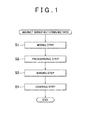
FIG. 1 is a flowchart illustrating a magnet manufacturing method according to an embodiment of the invention; -
FIG. 2A is a view illustrating the initial state of a mixing step inFIG. 1 ; -
FIG. 2B is a view illustrating the state at the completion of the mixing step inFIG. 1 ; -
FIG. 3A is a view illustrating the initial state of a pressurizing step inFIG. 1 ; -
FIG. 3B is a view illustrating the intermediate state of the pressurizing step inFIG. 1 ; -
FIG. 3C is a view illustrating the state at the completion of the pressurizing step inFIG. 1 ; -
FIG. 4 is a schematic view of the structural section of a primary compact at the completion of the pressurizing step; -
FIG. 5 is a schematic view of the structural section of a secondary compact at the compression of a baking step inFIG. 1 ; -
FIG. 6 is a schematic view of the structural section of a tertiary compact at the completion of a coating step inFIG. 1 ; -
FIG. 7 is a process chart of a heating process in the baking step inFIG. 1 ; -
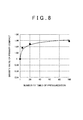
FIG. 8 is a graph indicating the relationship between the number of times of pressurization in the pressurizing step and the density ratio of the primary compact; and -
FIG. 9 is a table indicating the density ratios of the primary compact achieved by changing the number of times of pressurization and presence or absence of heating in the pressurizing step. - Hereinafter, a magnet manufacturing method according to an embodiment of the invention will be described with reference to
FIG. 1 to FIG. 7 .Magnetic powders 10, which are made of a hard magnetic material used as a material of a magnet, andlubricant 60, which is in a powdery state at ordinary temperature, are prepared. In the present embodiment, any bonding agent such as resin, which is conventionally used, is not used. - As illustrated in
FIG. 1 andFIG. 2A , themagnetic powders 10 and thelubricant 60, which are prepared as described above, are placed in amixing bowl 1 such as a mortar, and are mixed to produce a powder mix 70 (step S1 inFIG. 1 ). - As the
magnetic powders 10, a R-Fe-Ne compound that contains a rare earth element as R, or a Fe-N compound is used. Rare earth elements other than dysprosium, such as light rare earth elements, are preferably used as the rare earth element R. Among light rare earth elements, Sm is particularly preferable. Note that, in this specification, the light rare earth elements are lanthanoid elements having an atomic weight smaller than that of Gd, namely, La, Ce, Pr, Nd, Pm, Sm, Eu. Specifically, Sm2Fe17N3 or Fe16N2 is preferably used as themagnetic powders 10. The average particle diameter of themagnetic powders 10 is approximately 2 to 5 µm. Because hard magnetic material that does not require dysprosium is used, the magnet is manufactured at low costs. Further, as themagnetic powders 10, magnetic powders with oxide films formed partially on their surfaces are used. - As the
lubricant 60, metallic soap powders are used. For example, the stearic acid metal powders such as zinc stearate powders are used as thelubricant 60. The average particle diameter of thelubricant 60 is approximately 10 µm. That is, the average particle diameter of thelubricant 60 is larger than that of themagnetic powders 10. Thelubricant 60 has a specific weight that is smaller than that of themagnetic powders 10. Thus, by setting the average particle diameter of thelubricant 60 in the initial state to a relatively large value, the mass of one particle of thelubricant 60 is made larger. Thus, it is possible to restrain thelubricant 60 from scattering in the air during mixing of thelubricant 60 and themagnetic powders 10. - The volume ratio between the
magnetic powders 10 and thelubricant 60 is set such that themagnetic powders 10 have 80 to 90 volume percent and thelubricant 60 has 5 to 15 volume percent with an additive as the remainder. Themagnetic powders 10 and thelubricant 60 are mixed with each other while being ground in themixing bowl 1. Because themagnetic powders 10 and thelubricant 60 are ground while being mixed with each other, thelubricant 60 having a low bond strength is fragmented, as illustrated inFIG. 2B , and thus the particle diameter of thelubricant 60 is reduced as a whole. Thus, thelubricant 60 having different particle diameters is present after a mixing step is completed. - At the completion of the mixing step, in the
powder mix 70, the amount of massive part formed only of themagnetic powders 10 is reduced and the size of thelubricant 60 is also reduced. That is, the finelyfragmented lubricant 60 is present in the vicinity of each of themagnetic powders 10. - Next, as indicated in step S2 in
FIG. 1 , thepowder mix 70 is pressurized to form a primary compact 100 as illustrated inFIG. 3C andFIG. 4 (pressurizing step). The pressurizing step will be described in detail with referenceFIG. 3A to FIG. 3C . - At first, as illustrated in
FIG. 3A , thepowder mix 70 formed of themagnetic powders 10 and thelubricant 60 in a powdery state is placed in amold 2. Then, by moving a mold 3 (upper mold) as illustrated inFIG. 3B , thepowder mix 70 is pressurized by themolds molds - Pressurization by the
molds mold 3, the pressure applied to themold 3 is once released, and then, a pressure is again applied to themold 3. This process is repeated. When the pressure applied to themold 3 is released, themold 3 may be moved upward or the pressure may be just lowered without moving themold 3 upward. - In the pressurizing step, the
molds powder mix 70 in themolds powder mix 70 is set to a temperature (first temperature) that is lower than a decomposition temperature Te2 of themagnetic powders 10 but is equal to or higher than a melting point of thelubricant 60. Thus, themagnetic powders 10 are not decomposed. Thelubricant 60 that is in a solid state (powdery state) at normal temperature is turned into liquid because thelubricant 60 is heated up to a temperature equal to or higher than its melting point during the pressurizing step. - Thus, during the pressurization of the
magnetic powders 10 in thepowder mix 70, thelubricant 60 is not solid but liquid having a viscosity corresponding to the temperature. It is needless to say that the higher the heating temperature (the first temperature) is, the lower the viscosity of thelubricant 60 is. Thelubricant 60 that is turned into liquid uniformly sticks to the external surfaces of themagnetic powders 10 without segregation. The shape of thelubricant 60 is not illustrated inFIG. 3B . - With the repetitions of the pressurization, as illustrated in
FIG. 3C , clearances between themagnetic powders 10 are gradually reduced and then the primary compact 100 in which the clearances between themagnetic powders 10 are small is formed. This is because themagnetic powders 10 are re-arranged with respect to the arrangement of themagnetic powders 10 during the immediately preceding pressurization, due to pressurization carried out multiple times. In themolds lubricant 60 in the liquid form is present between the adjacentmagnetic powders 10, themagnetic powders 10 are able to move relative to each other considerably smoothly. Due to the synergistic effect between the re-arrangement of themagnetic powders 10 and the slipping effect provided by thelubricant 60, the clearances between themagnetic powders 10 in the primary compact 100 become smaller. - Next, as indicated in step S3 in
FIG. 1 , the primary compact 100 formed in the pressurizing step is heated in an oxidizing atmosphere to form a secondary compact 200 (baking step).FIG. 4 is a schematic view of the structural section of the primary compact 100 before the baking step. As illustrated inFIG. 4 ,clearances 20 are present between themagnetic powders 10.FIG. 5 is a schematic view of the structural section of the secondary compact 200 after the heating. - Because the
primary compact 100 is heated in the oxidizing atmosphere, the exposed surfaces of themagnetic powders 10 react chemically with oxygen to create oxide films 30 (indicated by the bold lines inFIG. 5 ) on the outer surfaces of themagnetic powders 10. Theoxide films 30 bond the outer surfaces of the adjacentmagnetic powders 10 to each other. That is, theoxide films 30 are formed on the outer surfaces of themagnetic powders 10 only at portion exposed to theclearances 20, and portions of the outer surfaces of themagnetic powders 10, which are not exposed to theclearances 20, serve as base materials. Thus, theoxide films 30 are not formed over the entire outer surfaces of themagnetic powders 10. - The thus formed secondary compact 200 has a sufficient strength. Thus, it is possible to enhance the bending strength of the
secondary compact 200. Further, by reducing the region where nomagnetic powders 10 are present in the primary compact 100 in the pressurizing step, the residual magnetic flux density of the secondary compact 200 after the baking step is increased. Note that the secondary compact 200 has a density of approximately 5 to 6 g/cm3. - The baking step is carried out with the primary compact 100 placed in a heating furnace in which heating is carried out using microwaves, an electric furnace, a plasma furnace, a high frequency heating furnace, a heating furnace in which heating is carried out using an infrared heater or the like. The temperature profile of the heating during the baking step is as illustrated in
FIG. 7 . - As illustrated in
FIG. 7 , a heating temperature Te1 (second temperature) is set lower than the decomposition temperature Te2 of the compound of themagnetic powders 10. For example, when Sm2Fe17N3 or Fe16N2 is used as themagnetic powders 10, the decomposition temperature Te2 is approximately 500 deg C, and thus the heating temperature Te1 is set lower than 500 deg C. For example, the heating temperature in the baking step is set to a value within a range from approximately 200 to 300 deg C. - The oxygen concentration and the pressure of the oxidizing atmosphere are not particularly limited as long as the
magnetic powders 10 are oxidized, and may be about the oxygen concentration in the atmospheric air and the atmospheric pressure, respectively. Thus, it is not necessary to specially control the oxygen concentration and the pressure. Thus, the heating may be carried out in the atmosphere. By setting the heating temperature Te1 (second temperature) to a value within a range from approximately 200 to 300 deg C, theoxide films 30 are formed regardless of whether Sm2Fe17N3 or Fe16N2 is used as themagnetic powders 10. - Next, as indicated in step S4 in
FIG. 1 and as illustrated inFIG. 6 , the surface of the secondary compact 200 formed in the baking step is covered with acoating film 40 to form a tertiary compact 300 (coating step). - The
coating film 40 formed on the tertiary compact 300 is a plating film that is formed of a material such as Cr, Zn, Ni, Ag or Cu by electroplating or a plating film that is formed by electroless plating. Examples of electroless plating include electroless plating formed of Ni, Au, Ag, Cu, Sn, Co or an alloy or a mixture of these metals. Alternatively, thecoating film 40 may be a resin film formed by resin coating, a glass film formed by glass coating or a film made of Ti, diamond-like carbon (DLC) or the like. Examples of resin coating include silicon resin coating, fluororesin coating, and urethane resin coating. - That is, the
coating film 40 formed on the tertiary compact 300 functions like an eggshell. Because both theoxide films 30 and thecoating film 40 exhibit a bond strength, the bending strength of the tertiary compact 300 is enhanced. In particular, application of the electroless plating enhances the surface hardness and the adherence of thecoating film 40, and thus the bond strength of themagnetic powders 10 is further enhanced. For example, nickel-phosphorus electroless plating exhibits a satisfactory corrosion resistance. - Further, as described above, the
oxide films 30 bond themagnetic powders 10 to each other not only at the outer surface of the secondary compact 200 but also in the inside of thesecondary compact 200. Thus, the bond strength provided by theoxide films 30 restricts free movement and rotation of themagnetic powders 10 inside thetertiary compact 300. Thus, the adjacentmagnetic powders 10 are restrained from being arranged such that their magnetic poles are reversed to each other due to the rotation of themagnetic powders 10. Thus, it is possible to restrict a reduction in the residual magnetic flux density of the entirety of thetertiary compact 300. As a result, it is possible to obtain a magnet having a high residual magnetic flux density. - When the electroplating is applied in the coating step, the bond strength of the secondary compact 200 needs to be increased because the secondary compact 200 before the plating serves as an electrode. On the other hand, when the electroless plating, the resin coating or the glass coating is applied in the coating step, it is not necessary to set the bond strength of the secondary compact 200 as high as that in the case of the electroplating. That is, the bond strength provided by the
oxide films 30 is sufficient. Thus, thecoating film 40 is reliably formed on the outer surface of the secondary compact 200 in the coating step in which the above-described electroless plating, resin coating or glass coating is applied. - When the electroless plating is applied in the coating step, the secondary compact 200 is immersed in a plating solution. At this time, the plating solution attempts to enter the inside of the secondary compact 200, but the
oxide films 30 that are formed in the secondary compact 200 exhibit a function restricting the entry of the plating solution into thesecondary compact 200. Thus, it is expected that theoxide films 30 will restrict occurrence of corrosion or the like caused by the entry of the plating solution into thesecondary compact 200. - As described above, the
powder mix 70 is repeatedly pressurized by themolds primary compact 100, which varies as the number of times of pressurization is changed, will be described with reference toFIG. 8 . In this case, no heating at the first temperature was carried out in the pressurizing step in order to clarify the relationship between the number of times of pressurization and the density ratio. -
FIG. 8 is a graph obtained by plotting density ratios when the number of times of pressurization was successively set to 2, 20 and 100 in the case where the density ratio of theprimary compact 100, which is obtained when the number of times of pressurization is 1, was set to 1. InFIG. 8 , a curve indicated by a quadratic expression that approximates the plotting is also illustrated. - As illustrated in
FIG. 8 , by setting the number of times of pressurization to 2, theclearances 20 between themagnetic powders 10 became smaller than that when the number of times of pressurization is 1, and thus the density ratio of theprimary compact 100 was considerably increased. Even when the pressurization is carried out more than 30 times, theclearances 20 between themagnetic powders 10 remained nearly-unchanged. Thus, by setting the number of times of pressurization to a value within a range from 2 to 30, a magnet having a high residual magnetic flux density is reliably obtained while an increase in the man-hours for manufacturing the magnet is prevented. Although the evaluation was made on the primary compact 100 on which thecoating film 40 was formed, it is obvious that the relationship described above is obtained on the secondary compact 200 and thetertiary compact 300. - Next, the density of the
primary compact 100 was examined in each of the case where the number of times of pressurization in the pressurizing step was 1 and heating at the first temperature in the pressurizing step was not carried out, the case where the number of times of pressurization in the pressurizing step was 1 and heating at the first temperature in the pressurizing step was carried out, the case where the number of times of pressurization in the pressurizing step was 30 and heating at the first temperature in the pressurizing step was not carried out, and the case where the number of times of pressurization in the pressurizing step was 30 and heating at the first temperature in the pressurizing step was carried out. There are 4 manufacturing conditions obtained by combining the numbers of times of pressurization and presence or absence of heating in the pressurizing step, that is,cases 1 to 4 indicated inFIG. 9 . - In the
cases 1 to 4, the density ratios of the primary compact 100 were as illustrated inFIG. 9 . The density ratio of the primary compact 100 obtained when the number of times of pressurization was 1 and heating in the pressurizing step was not carried out was set to 1. In thecase 2, the density ratio of theprimary compact 100 was increased by carrying out the heating even though the number of times of pressurization was 1. - In view of the relationship between the
case 1 and thecase 3, and the relationship between thecase 2 and thecase 4, the rates of increase in the density ratio of the primary compact 100 achieved by changing the number of times of pressurization from 1 to 30 were substantially the same. That is, as understood from thecase 4, by setting the number of times of pressurization to 30 and carrying out the heating in the pressurizing step, the effects due to an increase in the number of times of pressurization and the heating were exhibited. As a result, the density of theprimary compact 100 was increased. - In the above-described embodiment, the heating of the
powder mix 70 in the pressurizing step was carried out by heating themolds 2. 3. Alternatively, thepowder mix 70 may be heated up to the first temperature just before thepowder mix 70 is placed in themold 2. - In the above-described embodiment, the
lubricant 60 that is in a solid state (powdery state) at normal temperature is used. Alternatively, thelubricant 60 that is liquid at normal temperature may be used. Even in this case, in the mixing step, theliquid lubricant 60 and themagnetic powders 10 may be mixed with each other. By carrying out the heating in the pressurizing step, the viscosity of thelubricant 60 is lowered. Thus, thelubricant 60 is uniformly applied over the outer surfaces of themagnetic powders 10. As a result, themagnetic powders 10 smoothly move relative to each other. Thus, it is possible to increase the density of theprimary compact 100.
Claims (6)
- A magnet manufacturing method comprising:forming a primary compact by pressurizing magnetic powders made of a hard magnetic material formed of a R-Fe-N compound that contains a rare earth element as R or formed of a Fe-N compound, pressurizing multiple times by a mold; andcarrying out baking to form a secondary compact by heating the primary compact at a temperature lower than a decomposition temperature of the magnetic powders to bond together outer surfaces of the magnetic powders that are adjacent to each other.
- The magnet manufacturing method according to claim 1, wherein, during the baking, the secondary compact is formed by heating the primary compact in an oxidizing atmosphere to bond together the outer surfaces of the magnetic powders with oxide films formed on the outer surfaces of the magnetic powders.
- The magnet manufacturing method according to claim 1 or 2, wherein the pressurizing is repeated 2 to 30 times.
- The magnet manufacturing method according to claim 2, wherein:during the pressurizing, the primary compact is formed by pressurizing the magnetic powders by the mold while the magnetic powders and a lubricant placed in the mold are heated at a first temperature that is lower than the decomposition temperature of the magnetic powders and equal to or higher than a melting point of the lubricant; andduring the baking, the secondary compact is formed by heating the primary compact at a second temperature that is lower than the decomposition temperature of the magnetic powders to bond together the outer surfaces of the magnetic powders adjacent to each other.
- The magnet manufacturing method according to claim 4, further comprising mixing the magnetic powders and the lubricant in a powdery state with each other to prepare a powder mix, wherein
during the pressurizing, the primary compact is formed by pressurizing the powder mix placed in the mold while heating the powder mix at the first temperature. - A magnet manufactured by the magnet manufacturing method according to any of claims 1 to 5.
Applications Claiming Priority (2)
| Application Number | Priority Date | Filing Date | Title |
|---|---|---|---|
| JP2013132540A JP2015008200A (en) | 2013-06-25 | 2013-06-25 | Method of manufacturing magnet and magnet |
| JP2013132541A JP2015008201A (en) | 2013-06-25 | 2013-06-25 | Magnet manufacturing method and magnet |
Publications (1)
| Publication Number | Publication Date |
|---|---|
| EP2822003A1 true EP2822003A1 (en) | 2015-01-07 |
Family
ID=50979635
Family Applications (1)
| Application Number | Title | Priority Date | Filing Date |
|---|---|---|---|
| EP14173515.9A Withdrawn EP2822003A1 (en) | 2013-06-25 | 2014-06-23 | Magnet manufacturing method and magnet |
Country Status (3)
| Country | Link |
|---|---|
| US (1) | US20140374643A1 (en) |
| EP (1) | EP2822003A1 (en) |
| CN (1) | CN104252966A (en) |
Cited By (3)
| Publication number | Priority date | Publication date | Assignee | Title |
|---|---|---|---|---|
| EP3086332A1 (en) * | 2015-04-16 | 2016-10-26 | Jtekt Corporation | Magnet manufacturing method and magnet |
| EP3089174A1 (en) * | 2015-04-16 | 2016-11-02 | Jtekt Corporation | Magnet manufacturing method and magnet |
| EP3118864A1 (en) * | 2015-07-08 | 2017-01-18 | Jtekt Corporation | Manufacturing method for magnet and magnet |
Families Citing this family (4)
| Publication number | Priority date | Publication date | Assignee | Title |
|---|---|---|---|---|
| JP2013175650A (en) * | 2012-02-27 | 2013-09-05 | Jtekt Corp | Magnet manufacturing method and magnet |
| JP6003085B2 (en) | 2012-02-27 | 2016-10-05 | 株式会社ジェイテクト | Magnet manufacturing method |
| WO2016144811A1 (en) * | 2015-03-06 | 2016-09-15 | SDCmaterials, Inc. | Coated magnetic particle and methods of making and using the same |
| US20160379755A1 (en) * | 2015-06-24 | 2016-12-29 | Jtekt Corporation | Manufacturing method for magnet and magnet |
Citations (11)
| Publication number | Priority date | Publication date | Assignee | Title |
|---|---|---|---|---|
| JPS62206801A (en) | 1986-03-07 | 1987-09-11 | Tohoku Metal Ind Ltd | Manufacture of rare earth magnet |
| EP0481224A1 (en) * | 1990-09-18 | 1992-04-22 | Kanegafuchi Kagaku Kogyo Kabushiki Kaisha | Permanent magnet having high corrosion resistance, a process for making the same and a process for making a bonded magnet having high corrosion resistance |
| JPH1072603A (en) * | 1996-09-02 | 1998-03-17 | Toyota Central Res & Dev Lab Inc | Manufacturing method of magnetic material |
| US6317020B1 (en) * | 1999-05-19 | 2001-11-13 | Kabushiki Kaisha Toshiba | Bond magnet and manufacturing method thereof, and actuator therewith |
| JP2005223263A (en) | 2004-02-09 | 2005-08-18 | Sumitomo Metal Mining Co Ltd | Rare earth permanent magnet manufacturing method and obtained rare earth permanent magnet |
| JP2007039794A (en) | 2005-06-30 | 2007-02-15 | Toyota Motor Corp | Method for producing hard magnetic alloy nanoparticles and method for producing nanocomposite magnets |
| WO2010071111A1 (en) * | 2008-12-15 | 2010-06-24 | 住友金属鉱山株式会社 | Iron-based magnetic alloy powder containing rare earth element, method for producing same, resin composition for bonded magnet obtained from same, bonded magnet, and compacted magnet |
| EP2228808A1 (en) * | 2007-11-02 | 2010-09-15 | Asahi Kasei Kabushiki Kaisha | Composite magnetic material for magnet and method for manufacturing such material |
| JP2012069962A (en) | 2011-10-19 | 2012-04-05 | Asahi Kasei Chemicals Corp | Solid material for magnets |
| EP2631918A2 (en) * | 2012-02-27 | 2013-08-28 | JTEKT Corporation | Method of manufacturing magnet and magnet |
| EP2680280A1 (en) * | 2012-06-25 | 2014-01-01 | Jtekt Corporation | Method of manufacturing magnet and magnet |
-
2014
- 2014-06-13 US US14/304,360 patent/US20140374643A1/en not_active Abandoned
- 2014-06-23 EP EP14173515.9A patent/EP2822003A1/en not_active Withdrawn
- 2014-06-24 CN CN201410286894.5A patent/CN104252966A/en active Pending
Patent Citations (11)
| Publication number | Priority date | Publication date | Assignee | Title |
|---|---|---|---|---|
| JPS62206801A (en) | 1986-03-07 | 1987-09-11 | Tohoku Metal Ind Ltd | Manufacture of rare earth magnet |
| EP0481224A1 (en) * | 1990-09-18 | 1992-04-22 | Kanegafuchi Kagaku Kogyo Kabushiki Kaisha | Permanent magnet having high corrosion resistance, a process for making the same and a process for making a bonded magnet having high corrosion resistance |
| JPH1072603A (en) * | 1996-09-02 | 1998-03-17 | Toyota Central Res & Dev Lab Inc | Manufacturing method of magnetic material |
| US6317020B1 (en) * | 1999-05-19 | 2001-11-13 | Kabushiki Kaisha Toshiba | Bond magnet and manufacturing method thereof, and actuator therewith |
| JP2005223263A (en) | 2004-02-09 | 2005-08-18 | Sumitomo Metal Mining Co Ltd | Rare earth permanent magnet manufacturing method and obtained rare earth permanent magnet |
| JP2007039794A (en) | 2005-06-30 | 2007-02-15 | Toyota Motor Corp | Method for producing hard magnetic alloy nanoparticles and method for producing nanocomposite magnets |
| EP2228808A1 (en) * | 2007-11-02 | 2010-09-15 | Asahi Kasei Kabushiki Kaisha | Composite magnetic material for magnet and method for manufacturing such material |
| WO2010071111A1 (en) * | 2008-12-15 | 2010-06-24 | 住友金属鉱山株式会社 | Iron-based magnetic alloy powder containing rare earth element, method for producing same, resin composition for bonded magnet obtained from same, bonded magnet, and compacted magnet |
| JP2012069962A (en) | 2011-10-19 | 2012-04-05 | Asahi Kasei Chemicals Corp | Solid material for magnets |
| EP2631918A2 (en) * | 2012-02-27 | 2013-08-28 | JTEKT Corporation | Method of manufacturing magnet and magnet |
| EP2680280A1 (en) * | 2012-06-25 | 2014-01-01 | Jtekt Corporation | Method of manufacturing magnet and magnet |
Cited By (3)
| Publication number | Priority date | Publication date | Assignee | Title |
|---|---|---|---|---|
| EP3086332A1 (en) * | 2015-04-16 | 2016-10-26 | Jtekt Corporation | Magnet manufacturing method and magnet |
| EP3089174A1 (en) * | 2015-04-16 | 2016-11-02 | Jtekt Corporation | Magnet manufacturing method and magnet |
| EP3118864A1 (en) * | 2015-07-08 | 2017-01-18 | Jtekt Corporation | Manufacturing method for magnet and magnet |
Also Published As
| Publication number | Publication date |
|---|---|
| US20140374643A1 (en) | 2014-12-25 |
| CN104252966A (en) | 2014-12-31 |
Similar Documents
| Publication | Publication Date | Title |
|---|---|---|
| US20140374643A1 (en) | Magnet manufacturing method and magnet | |
| US8562756B2 (en) | NdFeB sintered magnet and method for producing the same | |
| EP2945172B1 (en) | Soft magnetic metal powder and soft magnetic metal powder core using the same | |
| CN107658087B (en) | R-T-B sintered magnet | |
| JPWO2018163967A1 (en) | Magnet powder containing Sm-Fe-N-based crystal particles, sintered magnet produced therefrom, and production method thereof | |
| CN111261352B (en) | Method for producing R-T-B permanent magnet | |
| US20160303651A1 (en) | Magnet Manufacturing Method And Magnet | |
| CN108231392A (en) | The method for preparing rare-earth permanent magnet | |
| JP2014203922A (en) | Production method of magnet and magnet | |
| JP2008277775A (en) | Dust core and its manufacturing method | |
| JPH07283016A (en) | Magnet and production thereof | |
| JP2015008200A (en) | Method of manufacturing magnet and magnet | |
| EP0675511A1 (en) | Material for permanent magnet, production method thereof and permanent magnet | |
| EP2518742B1 (en) | R-T-B system permanent magnet | |
| EP3089174A1 (en) | Magnet manufacturing method and magnet | |
| KR101744403B1 (en) | Manufacturing method of rare-earth magnet | |
| KR101837280B1 (en) | Method of manufacturing a Rare Earth Sintering Magnet | |
| EP2680280A1 (en) | Method of manufacturing magnet and magnet | |
| JP2812152B2 (en) | Magnetic body and method of manufacturing the same | |
| JPH09223617A (en) | Rare earth-B-Fe based sintered magnet excellent in corrosion resistance and magnetic properties and method for producing the same | |
| JP2015008201A (en) | Magnet manufacturing method and magnet | |
| JP2014192460A (en) | Method of manufacturing r-t-x based powder-compacted magnet, and r-t-x based powder-compacted magnet | |
| EP3086332A1 (en) | Magnet manufacturing method and magnet | |
| JPH0554683B2 (en) | ||
| JP2014199845A (en) | Method of manufacturing composition for metal powder containing resin molded body, preforming body, method of manufacturing metal sintered body, and rare earth sintered magnet |
Legal Events
| Date | Code | Title | Description |
|---|---|---|---|
| PUAI | Public reference made under article 153(3) epc to a published international application that has entered the european phase |
Free format text: ORIGINAL CODE: 0009012 |
|
| 17P | Request for examination filed |
Effective date: 20140623 |
|
| AK | Designated contracting states |
Kind code of ref document: A1 Designated state(s): AL AT BE BG CH CY CZ DE DK EE ES FI FR GB GR HR HU IE IS IT LI LT LU LV MC MK MT NL NO PL PT RO RS SE SI SK SM TR |
|
| AX | Request for extension of the european patent |
Extension state: BA ME |
|
| STAA | Information on the status of an ep patent application or granted ep patent |
Free format text: STATUS: THE APPLICATION IS DEEMED TO BE WITHDRAWN |
|
| 18D | Application deemed to be withdrawn |
Effective date: 20150708 |