EP2821187A2 - Processing device and processing method - Google Patents
Processing device and processing method Download PDFInfo
- Publication number
- EP2821187A2 EP2821187A2 EP14174561.2A EP14174561A EP2821187A2 EP 2821187 A2 EP2821187 A2 EP 2821187A2 EP 14174561 A EP14174561 A EP 14174561A EP 2821187 A2 EP2821187 A2 EP 2821187A2
- Authority
- EP
- European Patent Office
- Prior art keywords
- conveyor
- workpieces
- robot
- workpiece
- processing
- Prior art date
- Legal status (The legal status is an assumption and is not a legal conclusion. Google has not performed a legal analysis and makes no representation as to the accuracy of the status listed.)
- Granted
Links
Images


Classifications
-
- B—PERFORMING OPERATIONS; TRANSPORTING
- B25—HAND TOOLS; PORTABLE POWER-DRIVEN TOOLS; MANIPULATORS
- B25J—MANIPULATORS; CHAMBERS PROVIDED WITH MANIPULATION DEVICES
- B25J9/00—Programme-controlled manipulators
- B25J9/0093—Programme-controlled manipulators co-operating with conveyor means
-
- B—PERFORMING OPERATIONS; TRANSPORTING
- B25—HAND TOOLS; PORTABLE POWER-DRIVEN TOOLS; MANIPULATORS
- B25J—MANIPULATORS; CHAMBERS PROVIDED WITH MANIPULATION DEVICES
- B25J9/00—Programme-controlled manipulators
- B25J9/0084—Programme-controlled manipulators comprising a plurality of manipulators
Definitions
- the invention relates to a processing device and a processing method having the features in the preamble of the method and device main claim.
- processing devices with industrial robots in the form of individual robot cells or machining lines are known in which the workpieces are transported by a controlled driven conveyor on pallets or other workpiece carriers through the stations of a production line or from cell to cell.
- Such conveyors are e.g. designed as Hubshuttle, roller or chain conveyor. It is also known to transport the workpieces by means of handling robots in a cell linking. In all these cases, extensive safety measures for operating and accident protection are required for legal reasons.
- the invention solves this problem with the features in the method and device main claim.
- the claimed processing technique i.
- the processing equipment and the processing method have the advantage of reducing the safety effort and improving the performance and the economy.
- the processing of the workpieces by an industrial robot and / or by a worker takes place during the workpiece transport on the conveyor.
- the workpieces can be temporarily at rest during processing and occupy a possibly defined working position.
- the workpieces can be processed during the transport movement on the conveyor or on the fly.
- the claimed processing technique also has the advantage of high flexibility. It can be changed in its configuration and size, in particular adjusted and also extended or reduced. It is also flexible and can be used for different purposes Workpieces are used.
- the processing device can be designed to be mobile and can be used as needed at different locations. In addition, a chaining or networking of multiple processing facilities without much effort and in particular without special security arrangements is possible.
- the combination of a designed as a gravity conveyor conveyor with an automated process area with an industrial robot has other advantages.
- Such an industrial robot can not only be used for the actual machining process, e.g. used for assembly or joining tasks, but also for conveyor technology purposes. This also optimizes the construction, control and energy costs.
- a possibly required safety effort depends only on the type and design of the industrial robot and is limited accordingly.
- An automated process area may be shielded by a personal access device.
- an industrial robot which is designed as a tactile robot, in particular as a MRK-capable robot.
- a tactile robot may include one or more robot axes a force control or force control or a combination of a position control or position control with a force control or force control. It can also have an integrated sensor system arranged on the robot axes.
- an industrial robot as a tactile robot with one or more robot axes with a compliance control, in particular a pure force control or a combined position and force control, and an integrated, stress-absorbing sensors formed.
- Such a tactile and MRK capable robot has several advantages. He can get along because of the reduced risk of accidents without protection. It also allows a combination with a manual work station in the immediate vicinity of the conveyor. In addition, the workplace can optionally be manual or automated, whereby a change can take place. In the claimed processing technology, it is generally possible to arrange automated and manual process areas on the conveyor. When using such a tactile robot, these process areas can be mixed or overlap each other.
- the processing technique may also include a buffer area that can serve different purposes.
- a buffer area can be arranged for several workpieces or workpiece carriers.
- the buffer area can also be present several times.
- the buffer area can be a storage area in order to meet requirements and differences in the process and transport cycle and, if necessary, to achieve clock decoupling.
- a buffer area can also serve as a transfer and loading buffer for storing empty workpiece carriers.
- a buffer or storage area can be combined with a manual process area for a worker who performs here, for example, an inspection, quality inspection or the like.
- the working time of the worker can be used in an optimized way, in which the worker is present only temporarily and performs manual work in blocks on the collected in the buffer area workpieces and / or workpiece carriers and these are then removed in the block. While refilling the buffer area, the operator can do other work.
- the conveyor can be designed in different ways. It has e.g. one or more downwardly inclined and preferably substantially straight conveyor tracks on which workpiece carriers loaded with one or more workpieces are transported in a sliding or preferably rolling manner. The workpieces can be transported even with appropriate training without workpiece carrier and in direct contact with the conveyor track.
- the conveyor has a plurality of downwardly inclined, opposing conveyor tracks for flow and return of workpieces or workpiece carriers.
- the conveyor tracks can be the same direction and transport the workpieces in the same direction.
- the conveying device has at one end between adjacent, in particular counter-rotating conveying paths, a transfer device for the automatic transfer of a workpiece or a workpiece carrier. For the conversion It is also possible to use one of the aforementioned industrial robots.
- the workpieces or workpiece carriers can also be positioned on a conveyor track in a predetermined working position in an automatic or manual process area by means of a positioning device.
- a positioning device This may include a stop at a given location and possibly also a lift off the conveyor.
- the positioning device may e.g. have a stopper and / or a lifting device for a workpiece or a workpiece carrier.
- the positioning device can be designed such that it can be operated either by a worker or by an industrial robot.
- the workpiece or the workpiece carrier can also be pushed manually or by an industrial robot.
- the conveyor is preferably designed for a rolling transport and has for this purpose a plurality of rolling elements on the conveyor track or on a workpiece carrier.
- a braking device may be provided which is associated with a rolling body and this brakes.
- the braking device may have a mechanical brake or an electric brake, in particular an electric regenerative brake.
- About the braking device can be influenced with fixed specification or controllable braking effect on the workpiece or the workpiece carrier in a fixed or adjustable, in particular controllable manner. This allows the movements of a workpiece or a mobile workpiece carrier on the conveyor track and while driving are controlled. This can be done in particular in adaptation to the loading condition and the total weight of a loaded workpiece carrier. There is also an adaptation to the respective inclination of a conveyor track possible. In addition, congestion and collision situations can be better controlled.
- a particular advantage is the self-sufficient design of the braking device, which manages with the kinetic energy of the moving workpiece or workpiece carrier.
- An external energy supply and an external control influence are dispensable.
- an adaptation of a workpiece carrier to different application areas on different conveyor tracks or conveyors is possible.
- the braking device may have a starting device for a delayed entry of the braking effect, which allows a largely unrestrained approach movement. Furthermore, the braking device can have a regulating device for the braking effect, with which the movement speed of the workpiece or workpiece carrier is regulated, in particular one of the height can be limited and optionally also regulated to a predetermined value. The braking device may also have a selection device with which the braking effect can be influenced and adjusted in dependence on the direction of movement, in particular the direction of rotation of a rolling body. In particular, for different directions of movement, e.g. for flow and return, different large braking effects are set.
- the claimed machining technique has particular advantages for maximizing process performance and utilization of the industrial robot (s).
- several conveyor tracks can be arranged.
- the industrial robot can work alternately at different points or working positions and thus optimally be exploited.
- sequences of process steps on the one-piece or preferred multi-part workpieces can be optimized.
- An industrial robot, in particular a tactile robot which is particularly suitable for sensitive tasks can be used for similar and temporally and spatially staggered process jobs, in particular assembly jobs on a workpiece. This can, for example, first arrive in the supply and with time interval then again in the locally separate return to this industrial robot.
- the latter can use a uniform tool, for example a gripping tool, which minimizes set-up times and maximizes the use of robots.
- other process steps eg, other assembly and / or joining work, may be performed at one or more other locations on the conveyor.
- the industrial robot is preferably designed as articulated arm robot.
- the industrial robot can carry a fixed or exchangeable tool, in particular a gripping or joining tool.
- one or more of said industrial robots are arranged between adjacent and preferably parallel aligned conveyor tracks.
- this has advantages for the aforementioned multiple functions of such an industrial robot.
- further workplaces, in particular manual workstations may be provided on the outer side or sides of said conveyor tracks.
- a replaceable tool can also be arranged detachably on a workpiece carrier and be moved.
- a provision for a tool can be arranged on a workpiece carrier.
- a particular advantage of the claimed processing technique is the high flexibility. On the one hand can be done very quickly a conversion to other types of workpieces. In addition, different types of workpieces in the change, especially in free mix, transported and processed with the intended processes. For this purpose, if necessary, a tool change in the or the industrial robots done. Also, the aforementioned braking device can be adjusted accordingly.
- the industrial robot (s) may be mobile, e.g. be changed in their position by means of an adjustable holder on the frame of the processing device. They can also be detached from the bracket and removed or reassembled elsewhere on the rack.
- the conveyor is adjustable with a corresponding bracket.
- the one or more industrial robots can be arranged hanging and / or standing on the frame.
- An auxiliary device can be arranged on the frame.
- the processing device may be designed to be mobile, the frame being detachably arranged and having a transport aid, in particular forklift pockets.
- the number and arrangement of the one or more automated and / or. Manual process areas are changed.
- the number and arrangement of industrial robots within an automated process area can also be changed as desired.
- the length of the conveyor can be increased or decreased. It is also a concatenation or Networking of conveyors and processing facilities possible.
- the workpieces or workpiece carriers can be transported on the conveyor between opposing loading and unloading. They can also be circulated on the conveyor and loaded and unloaded in the same place.
- the loading and unloading can be done manually or automatically with a corresponding device, in particular also with one of said industrial robots, in particular a tactile robot.
- a pneumatic manual power assistance may be present, which supports the worker with limited force and thus requires no additional safety technology.
- the invention relates to a machining device (1) and a machining method for workpieces (2).
- the invention also relates to a processing system (46) having a plurality of interconnected Machining equipment (1).
- the workpieces (2) can be of any type and design and consist of any materials.
- the workpieces (2) may be in one piece or consist of several workpiece parts (13).
- the workpieces (2) or workpiece parts (13) are formed as body components of a vehicle. They preferably consist at least partially of metal.
- the one- or multi-part workpieces (2) are subjected to a machining process in the processing device (1).
- This can be designed in different ways. In particular, it can consist of a sequence of several process steps.
- the said process is a mounting process in which a plurality of initially separate workpiece parts (13) are connected and assembled in several process steps.
- one-piece and multi-part workpieces for the sake of simplicity are referred to uniformly as workpieces (2).
- the said process may be designed differently. It may, for example, be a joining process in which different workpiece parts are joined and joined together, eg by welding, soldering, gluing, folding or clinching or the like. In addition, other process variants with shaping processing of the work piece (2), eg forming, machining or the like possible. Further processes may be, for example, application or coating processes, marking processes or mixtures of the abovementioned different individual processes.
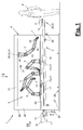
- FIG. 1 to 3 is a first variant of the processing device (1) in a side view according to FIG. 1 and in associated plan view and end view according to arrow II and III of FIG. 1 shown.
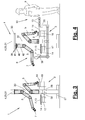
- FIGS. 4 to 7 show more variants.
- the processing device (1) has in each case a conveying device (3) for workpieces (2) and an automated process region (9) with an industrial robot (5, 6). In a process area (9) several and possibly different industrial robots (5,6) may be arranged.
- the processing device (1) can also have a plurality of automated process areas (9) each with one or more industrial robots (5, 6).
- the processing device (1) can also have a manual process area (10) for a worker (8), wherein this process area (10) can also be present multiple times. It can also be provided and designed for several workers (8).
- a buffer area (12) which may also be single or multiple.
- the process area (s) (9, 10) is / are associated with the conveyor (3).
- the workpieces (2) are processed on the conveyor (3). This can happen while stationary or during their transport movement.
- the workpieces (2) are on the conveyor (3). They can be arranged standing, hanging or in any other position.
- the industrial robots (5,6) may be formed in the same or different ways. This may relate in particular to their control or regulation described below.
- the industrial robots (5,6) may be formed substantially similar. They have a plurality of interconnected robot axes, which can be configured in any suitable manner and combination as a rotary and / or translatory robot axes.
- the industrial robots (5, 6) are articulated-arm robots having five or more rotary axes and possibly one or more additional axles, in particular a linear drive axle according to FIG FIG. 4 , educated.
- FIG. 1 3 shows by way of example that an industrial robot (5, 6) has an optionally rotatable base (42), a first robot arm (43) pivotably arranged thereon and a further robot arm (44) likewise pivotably mounted on the free end, and a multiaxial end member ( 45), eg a so-called robot hand.
- a multiaxial end member eg a so-called robot hand.
- This is connected in a 2-axis design on the one hand pivotally connected to the second robot arm (44) and has a rotating output element, for example, an output flange.
- the end or driven member (45) may also have three axes and have an additional, longitudinal axis of rotation.
- a suitable for the respective process or process step tool (7) is fixed or detachable, possibly arranged with the interposition of a robot (5,6) controllable change coupling.
- the tool (7) is designed as a gripping tool with which handling and assembly work can be carried out.
- the tool (7) may alternatively be designed as a joining tool, application tool, test tool or the like.
- the industrial robots (5,6) are each connected to a separate or a common robot controller (not shown).
- the industrial robots (5,6) are preferred as small robots with low weight of e.g. less than 50 kg and correspondingly low load capacity of e.g. less than 35 kg, trained. They can be designed in particular as so-called lightweight robots.
- the industrial robots (5,6) may differ in the aforementioned manner with regard to their control, in particular their axis control.
- the industrial robots (6) have a position control or position control of their robot axes and drive the stored in a control program positions of individual space points or a lane or regulated by means of a suitable monitoring sensor, if necessary, any obstacles or resistances on the way to be overcome if necessary ,
- a safety device (11) is provided for safety reasons, which in the variants of Figure 5 to 7 is shown and will be discussed below.
- One or more industrial robots (5) may alternatively be designed as tactile robots which, with their suitable movement, absorb externally acting loads, in particular forces and / or moments, during their movement, and take them into account in the control.
- Such a tactile industrial robot (5) can be used in particular for a machine-robot cooperation (MRK). be suitable trained. For this purpose, it can have a compliance control which brakes it or stops it in the event of unforeseen stress, eg a body contact with a worker (8).
- MMRK machine-robot cooperation
- a tactile industrial robot (5) has e.g. one or more force-controlled or force-controlled robot axes. It can also have an integrated, stress-absorbing sensor, wherein preferably each force-controlled or force-controlled robot axis is associated with a corresponding force and / or torque sensor.
- a tactile industrial robot (5) can also be equipped with a compliance control on one or more robot axes. This can e.g. be a pure force control or a combined position and force control.
- the tactile industrial robot (5) also in this case has an integrated and load-bearing sensor, e.g. Force and / or torque sensors on the respective robot axes, on.
- These tactile industrial robots (5) have sensitive properties and are particularly suitable for handling and assembly work. They can also be easily taught by hand.
- the processing device (1) has in the various variants in each case a frame (4) on which the conveyor (3) and the one or more industrial robots (5,6) are arranged together.
- the conveyor (3) can in this case fixed or by means of a in FIG. 1 shown bracket (38) adjustable on the frame (4) can be arranged.
- the one or more industrial robots (5, 6) can be fixed or adjustable or also detachable on the frame (4).
- bracket (39) with an aforementioned additional axis forming actuator (41) and / or be provided with a removable unit (40) for quick assembly.
- the industrial robots (5,6) can be arranged standing or suspended on the frame (4) in the various embodiments.
- the processing device (1) is shown in each case with different robot configurations.
- auxiliary devices (34) can be arranged rigidly or adjustably on the frame (4).
- the auxiliary devices (34) may optionally have their own drives and may be independently controllable or controllable. They may be formed, for example, as an independent pressing tool or assembly tool, eg for the assembly of rolling bearings, retaining rings, sealing rings or the like carried out by means of a tactile industrial robot (5) on a workpiece (2). In FIG. 1 such an auxiliary device (34) is shown schematically.
- the frame (4) can be designed in different ways. In the illustrated and preferred embodiments, it has a portal shape. It consists of a base frame (27) for supporting on a substrate, such as a hall floor and a philosophicalgestell (29) arranged thereon. This can have one, two or more upright uprights (30), between which an upper, longitudinally oriented support (31) and optionally a lower or middle parallel support (32) can be arranged to form the portal shape.
- the one or more industrial robots (5, 6) are arranged, for example, standing or hanging on the supports (31, 32) extending between the uprights (30). Also a laterally offset arrangement on a, connected to a support (31,32) transverse yoke (33) according to FIG. 4 is possible.
- the arrangement and attachment can be fixed or in the aforementioned manner be solvable. For this purpose, if necessary, several prepared mounting points or brackets (39) may be present.
- the frame (4) and with it the processing device (1) can be designed to be mobile and transportable.
- a transport aid (28) may be provided.
- the eg according to FIG. 1 consists of one or more forklift pockets which receive for transport the fork or other means of transport of a corresponding delivery, such as a forklift.
- the conveyor (3) operates as a gravity conveyor and has one or more downwardly inclined conveyor tracks (17,18) for guided transport for workpieces (2) or workpiece carrier (14).
- the workpieces (2) can be transported in direct support on a correspondingly formed conveyor track (17,18) sliding or rolling.
- workpiece transport is by means of one or more workpiece carriers (14).
- the illustrated and described embodiments show this variant and can be modified accordingly to a direct workpiece support.
- the workpiece carriers (14) are preferably conveyed rolling on the conveyor belt or tracks (17, 18) by gravity and their own weight.
- the conveying device (3) has a plurality of rotatable rolling bodies (15) which can be arranged on a conveying track (17, 18) and / or on a workpiece carrier (14).
- Preferred is a rolling body assembly on a workpiece carrier (14).
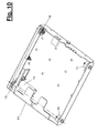
- FIG. 10 shows a workpiece carrier (14) in a perspective view and in bottom view. He has an example box-shaped frame on the side walls a plurality, eg four rolling elements (15) or wheels, are rotatably arranged.
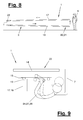
- the rolling bodies (15) may have a shape adapted to the geometry of the conveyor track (s) (17, 18), in particular a cylindrical or grooved jacket for preferably leading engagement with a contact surface, eg two parallel rails (19), a conveyor track (17 , 18).
- FIG. 9 clarifies this training.
- the rolling bodies (15) may have single axes or in pairs a common axis.
- two roller bodies (15) are arranged at both ends on a rotatable rocker.
- the rocker and the longitudinal side extend along the intended transport direction on a conveyor track (17,18).
- the workpiece carrier (14) has a braking device (16) which is associated with at least one rolling body (15) and brakes it in its rotational movement.
- a braking device can also be assigned to one or more rolling bodies on a conveyor track (17, 18).
- the braking device (16) includes a suitable brake, e.g. a mechanical brake or preferably an electric brake, in particular an electric regenerative brake.
- the braking effect can be fixed or variable, with a need for controlling the braking effect is possible.
- regenerative brake for example, a start-up device and / or a regulating device and / or a selection device for the above-described influencing the braking effect is provided.
- an electric regenerative brake one or more of these aforementioned devices may be formed as an electrical circuit (s).
- the power consumer may be variable and may be connected to a control device connected to a selector switch or other control element incorporated in FIG. 10 is shown on the right edge of the workpiece carrier (14).
- the braking device (16) can be adapted to the depending on the load condition, inclination, process requirements or the like other requirements with their braking effect.
- the workpiece carrier (14) may have on the upper side a workpiece holder (not shown) on which one or more workpieces (2) can be received in a predefined and defined position. This can also be a location reference to the respective conveyor track (17,18) are produced, with the workpiece carrier (14) is engaged.
- a location reference to the respective conveyor track (17,18) are produced, with the workpiece carrier (14) is engaged.
- FIG. 2 clarifies, on the exemplary pallet-like workpiece carrier (14) a plurality of workpiece parts (13) for a workpiece (2) to be mounted therefrom be received at predetermined locations.
- the industrial robot or robots (5, 6) can grasp, handle and assemble or otherwise process the workpiece parts (13) in a targeted and secure manner.
- the conveyor tracks (17,18) have a substantially linear and straight extension. You can alternatively have a curved course. You have a suitable downward slope for the transport of gravity of the workpiece or the workpiece carrier (14). The inclination and the total height can be adjusted via the aforementioned holder (38) on the frame (4) become.
- the one or more conveyor tracks (17,18) may be formed in one or more parts. They can consist of several successively arranged in the conveying direction segments.
- the conveyor track (s) (17, 18) may also have a variable length, e.g. by using the aforementioned segments, have.
- the conveyor track (s) (17,18) as a rail track (s) for rolling or alternatively sliding workpiece carrier (14) are formed.
- the conveyor track (s) (17,18) as a runway (s) may be formed with a plurality of preferably stationary and free or possibly brakable rotatable rolling elements.
- two conveyor tracks (17,18) are arranged side by side with substantially parallel orientation and possibly different inclinations on the frame (4).
- Arrows illustrate the transport direction of the work piece (2) or workpiece carrier (14), which can be moved in a circuit in this embodiment, wherein the conveyor track (17) the forward and the conveyor track (18) forms the return.
- a loading point (20) on the flow (17) and an unloading point (21) on the return (18) are arranged side by side.
- the conversion device (22) can be designed in different ways and is symbolized in the drawings by an arrow.
- the loading and unloading of the workpiece carriers (14) can be performed manually by the operator shown (8) or mechanically by a corresponding device, e.g. a loading robot, done.
- a manual or mechanical transfer of the workpiece carrier (14) from the return (18) on the lead (17) take place.
- the manual force can be reduced by a e.g. pneumatic device are supported.
- FIG. 1 shows a constructive embodiment of a transfer device (22) having a on the frame (4) arranged vertical lifting device to compensate for differences in height between the track ends and a horizontal carriage for the side transport between the conveyor tracks (17,18).
- the converting device (22) can grip and transfer the workpieces (2) or workpiece carriers (14) directly. It can alternatively have a in FIG. 1 and 8th detect indicated end portion of a conveyor track (17,18) and transport together with the workpiece thereon (2) or workpiece carrier (14). When converting can also be done a tilt adjustment of the web sections to the respective inclination of the conveyor track (17,18). In addition, a docking operation can be performed, which then allows a sliding or rolling onward transport of the converted workpiece carrier (14) by its own weight and gravity.
- the conversion device (22) can be controlled and driven, wherein the driving forces are limited and a compliance can be present. Alternatively, the conversion device (22) can be formed by an industrial robot (5, 6).
- FIG. 1 to 5 are several, for example, two conveyor tracks (17,18) on both sides of the frame (4) and in particular its structural frame (29) arranged. Between the conveyor tracks (17,18) are the or the automated process areas (9) and the industrial robot (s) there (5,6). In the working area there are thus two or more conveyor tracks (17,18). The industrial robot or robots (5, 6) can thereby work on one or more conveyor tracks (17, 18) located in particular in their working area and carry out process steps.
- the conveyor device (3) has one or more working positions (23) on the conveyor track (s) (17, 18) in the automated and optionally manual process area (9, 10), on which a workpiece carrier (14) for carrying out one or more process steps by an industrial robot (5,6) and / or a worker (8) can be temporarily stopped and positioned in a predetermined position.
- a positioning device (24) is arranged at the working position (23) at the working position (23).
- the positioning device (24) can have a stopper (25) and / or an excavating device (26) for a workpiece carrier (14).
- the positioning device (24) can be designed such that it can be operated manually by a worker (8) and / or by machine by an industrial robot (5, 6) with a corresponding tool (7).
- pivot lever provided on the short lever arm, a stop member and at its longer lever arm a weight are arranged. Due to the weight and its stop on a conveyor track (17,18), the stopper (25) is brought into a raised stop and positioning position for an incoming workpiece carrier (14).
- the positioning device (24) can also be designed so that the weight-loaded pivot lever acts as a lifting device and holds the workpiece carrier (14) in an optionally locked and raised position.
- the excavating device (26) can also be formed in other ways, for example by a manually or automatically actuated and possibly pneumatically driven lifting carriage.
- processing device (1) can be dispensed thanks to the use of tactile industrial robots (5) on a protective device.
- a tactile robot (5) it is possible for a tactile robot (5) to cooperate with a worker (8).
- a mutual replacement and exchange is possible.
- the processing device (1) can provide a supply (35) for workpieces or workpiece parts (13) and / or a supply (36) near the conveyor (3) and in the working area of an industrial robot (5, 6) and / or a worker (8). for tools (7).
- FIG. 4 shows by way of example both arrangements.
- an industrial robot (5, 6) can automatically change its tool (7) as needed.
- one or more feed devices (37) for workpiece parts (13) or workpieces on the periphery of the processing device (1) and in the aforementioned robot work areas be present.
- FIG. 5 is also a variant of the provision (36) for one or more interchangeable tools (7), which can be located on a workpiece carrier (14) and is moved along with this during transport.
- This has several advantages.
- special tools (7) adapted to the workpiece (2) or the workpiece parts (13) may be present in any variant width and nevertheless limited number. This benefits a particularly high flexibility.
- Such a tool (7) can be used temporarily and temporarily by several industrial robots (5, 6) and returned to the workpiece carrier (14). Despite the large variety of tools, the space required for deployments (36) remains small.
- FIG. 5 shows a variant of the processing device (1), which is largely with the above-described first variant of Figure 1 to 3 and the modification of FIG. 4 matches.
- one or more industrial robots (6) with a position control or position control for use.
- the associated and single or multiple existing automated process area (9) is therefore provided with a protective device (11), which shields him against personal access.
- This may be, for example, a fencing or enclosure surrounding the automated process area (9) and the industrial robot (s) (6).
- the conveyor (3) may extend with its conveyor track (s) (17,18) through the protective device (11), for which purpose suitable locks may be present.
- FIG. 5 also shows several feeders (37) extending into the automated process area (9). Furthermore, two initially mentioned buffer areas (12) are present.
- a first buffer area (12) can be connected to a Conveyor track (17), for example, be arranged on the flow, and before entering an automated process area (9). It can be designed as a storage or stacking area for a plurality of workpiece carriers (14) and can have corresponding devices.
- a worker (8) load a plurality of workpiece carriers (14) independently of the process clock and park in the buffer area (12) from which they are then retrieved automatically and eg with the help of an industrial robot (5,6) for further transport and the process sequence ,
- a further buffer area (12) may be arranged, which may be e.g. is located outside the protective device (11) and on which a manual process area (10) can be arranged.
- a worker (8) carry out inspection and testing or other process steps. In this case, decoupling from the process cycle and delivery cycle is again possible via the congestion.
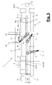
- FIG. 6 shows a variant too FIG. 5 in which the conveyor device (3) has a conveyor track (17) which is intended for one-way operation and the workpiece carriers (14) are conveyed through one or more process areas (9, 10) from one loading point (20) to an opposite unloading point (21). transported.
- the unloading point (21) can also be shielded by a protective device (11).
- a return transport of the empty workpiece carrier (14) is possible in different ways.
- a further conveyor track (18) for the return transport below the conveyor track or the flow (17) may be arranged.
- a such arrangement may, for example, accordingly FIG. 8 be educated.
- a transfer device (22) can also be present at the unloading point (21).
- the processing device (1) can also in this case have one or more buffer areas (12), a protective device (11) and one or more feed devices (37).
- a conveyor (3) with one-way function can also be used in an exclusive arrangement of tactile industrial robots (5).
- FIG. 6 are the industrial robot or (5,6) in another suitable manner to a frame, not shown, (4) fixed, adjustable or detachably arranged.
- FIG. 6 can also be modified to the effect that a workpiece processing on both superposed conveyor tracks (17,18) by appropriately arranged industrial robot (5,6).
- the web assembly can be vertically stacked with alignment or lateral offset.
- the loading and unloading can be arranged at the same end of the track as in the first embodiment, wherein a conversion device (22) is located at the other end of the track.
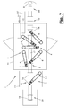
- FIG. 7 shows a modification opposite FIG. 6 , wherein the rear or left buffer area (12) is a pure storage area and may possibly also be designed as a further automated process area (9).
- the buffer area (12) is a pure storage area and may possibly also be designed as a further automated process area (9).
- a coupling of the buffer area (12) with a manual process area (10) is provided.
- a pure buffer function without further process area (9, 10) can be present.
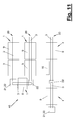
- FIG. 11 shows the above-mentioned processing plant (46), in which a plurality of processing devices (1) in a suitable manner coupled together and, for example in series or connected in parallel or even networked.
- the conveyors (3) can be connected or coupled in a suitable manner.
- a suitably adapted conversion device (22) can be used.
Abstract
Die Erfindung betrifft eine Einrichtung (1) und ein Verfahren zum Bearbeiten von Werkstücken (2), die auf einem Schwerkraftförderer (3) durch ihr Eigengewicht transportiert werden. Am Schwerkraftförderer (3) ist ein automatisierter Prozessbereich (9) mit einem Industrieroboter (5,6) und gegebenenfalls ein manueller Prozessbereich (10) angeordnet. Im Prozessbereich (9,10) erfolgt die Bearbeitung der Werkstücke (2) auf dem Schwerkraftförderer (3). Dies kann in einer ruhenden Arbeitsposition (23) oder während der Transportbewegung der Werkstücke (2) erfolgen.The invention relates to a device (1) and a method for processing workpieces (2) which are transported on a gravity conveyor (3) by their own weight. At the gravity conveyor (3) an automated process area (9) with an industrial robot (5,6) and possibly a manual process area (10) is arranged. In the process area (9, 10), the workpieces (2) are processed on the gravity conveyor (3). This can be done in a stationary working position (23) or during the transport movement of the workpieces (2).
Description
Die Erfindung betrifft eine Bearbeitungseinrichtung und ein Bearbeitungsverfahren mit den Merkmalen im Oberbegriff des Verfahrens- und Vorrichtungshauptanspruchs.The invention relates to a processing device and a processing method having the features in the preamble of the method and device main claim.
Aus der Praxis sind Bearbeitungseinrichtungen mit Industrierobotern in Form von einzelnen Roboterzellen oder von Bearbeitungslinien bekannt, bei denen die Werkstücke mit einer gesteuert angetriebenen Fördereinrichtung auf Paletten oder anderen Werkstückträgern durch die Stationen einer Fertigungslinie oder von Zelle zu Zelle transportiert werden. Solche Fördereinrichtungen sind z.B. als Hubshuttle, Rollen- oder Kettenförderer ausgebildet. Es ist auch bekannt, bei einer Zellenverkettung die Werkstücke mittels Handhabungsrobotern zu transportieren. In all diesen Fällen sind aus gesetzlichen Gründen umfangreiche Sicherheitsmaßnahmen zum Betriebs- und Unfallschutz erforderlich.In practice, processing devices with industrial robots in the form of individual robot cells or machining lines are known in which the workpieces are transported by a controlled driven conveyor on pallets or other workpiece carriers through the stations of a production line or from cell to cell. Such conveyors are e.g. designed as Hubshuttle, roller or chain conveyor. It is also known to transport the workpieces by means of handling robots in a cell linking. In all these cases, extensive safety measures for operating and accident protection are required for legal reasons.
In solchen durch angetriebene Fördereinrichtungen verbundenen Bearbeitungseinrichtungen kommen in der Regel auch positionsgesteuerte Industrieroboter zum Einsatz, die ebenfalls wegen der hiervon ausgehenden Unfallgefahr aufwändige Sicherheitsmaßnahmen bedingen.In such connected by driven conveyors processing equipment usually position-controlled industrial robots are used, which also require elaborate security measures because of the risk of accidents emanating therefrom.
In der Praxis ist es ferner bekannt, taktile und für eine Mensch-Roboter-Kooperation (Abk. MRK) taugliche Roboter mit einer Nachgiebigkeitsregelung einzusetzen. Derartige Industrieroboter können als Leichtbauroboter mit niedrigem Eigengewicht und begrenzter Tragkraft ausgebildet sein. Sie eignen sich durch ihre taktilen Fähigkeiten vor allem für Montageprozesse. Der Werkstücktransport erfolgt auch in diesen Fällen mittels gesteuert angetriebener Fördereinrichtungen in Verbindung mit entsprechenden Sicherheitsvorkehrungen.In practice, it is also known to use tactile and for a human-robot cooperation (abbr. MRK) capable robot with a compliance control. Such industrial robots can be designed as a lightweight robot with low weight and limited carrying capacity. Their tactile capabilities make them especially suitable for assembly processes. The workpiece transport takes place in these cases by means of controlled driven conveyors in conjunction with appropriate Safety precautions.
Es ist daher Aufgabe der vorliegenden Erfindung, eine verbesserte Bearbeitungstechnik aufzuzeigen.It is therefore an object of the present invention to provide an improved processing technique.
Die Erfindung löst diese Aufgabe mit den Merkmalen im Verfahrens- und Vorrichtungshauptanspruch.The invention solves this problem with the features in the method and device main claim.
Die beanspruchte Bearbeitungstechnik, d.h. die Bearbeitungseinrichtung und das Bearbeitungsverfahren haben den Vorteil einer Verringerung des Sicherheitsaufwands und einer Verbesserung der Leistungsfähigkeit und der Wirtschaftlichkeit.The claimed processing technique, i. The processing equipment and the processing method have the advantage of reducing the safety effort and improving the performance and the economy.
Die Bearbeitung der Werkstücke durch einen Industrieroboter und/oder durch einen Werker erfolgt während des Werkstücktransports auf der Fördereinrichtung. Die Werkstücke können während der Bearbeitung temporär in Ruhe sein und eine ggf. definierte Arbeitsposition einnehmen. Alternativ können die Werkstücke während der Transportbewegung auf der Fördereinrichtung bzw. on the fly bearbeitet werden.The processing of the workpieces by an industrial robot and / or by a worker takes place during the workpiece transport on the conveyor. The workpieces can be temporarily at rest during processing and occupy a possibly defined working position. Alternatively, the workpieces can be processed during the transport movement on the conveyor or on the fly.
Der Einsatz einer Fördereinrichtung mit Schwerkrafttransport der Werkstücke verringert den diesbezüglichen Sicherheits- und Bauaufwand. Insbesondere kann der Energie- und Steueraufwand minimiert werden. Zudem wird die Montage und Eingliederung der Fördereinrichtung in neue und bestehenden Bearbeitungseinrichtungen bzw. Bearbeitungsanlagen erleichtert.The use of a conveyor with gravity transport of the workpieces reduces the related safety and construction costs. In particular, the energy and tax expense can be minimized. In addition, the assembly and integration of the conveyor is facilitated in new and existing processing facilities or processing equipment.
Die beanspruchte Bearbeitungstechnik hat ferner den Vorteil einer hohen Flexibilität. Sie kann in ihrer Konfiguration und Größe verändert, insbesondere verstellt und auch erweitert oder verkleinert werden. Sie ist außerdem typflexibel und kann für unterschiedliche Werkstücke eingesetzt werden. Zudem kann die Bearbeitungseinrichtung mobil ausgebildet sein und kann sich bedarfsweise an unterschiedlichen Orten einsetzen lassen. Zudem ist eine Verkettung oder Vernetzung mehrerer Bearbeitungseinrichtungen ohne größeren Aufwand und insbesondere ohne besondere Sicherheitsvorkehrungen möglich.The claimed processing technique also has the advantage of high flexibility. It can be changed in its configuration and size, in particular adjusted and also extended or reduced. It is also flexible and can be used for different purposes Workpieces are used. In addition, the processing device can be designed to be mobile and can be used as needed at different locations. In addition, a chaining or networking of multiple processing facilities without much effort and in particular without special security arrangements is possible.
Die Kombination einer als Schwerkraftförderer ausgebildeten Fördereinrichtung mit einem automatisierten Prozessbereich mit einem Industrieroboter hat weitere Vorteile. Ein solcher Industrieroboter kann nicht nur für den eigentlichen Bearbeitungsprozess, z.B. für Montageoder Fügeaufgaben, sondern auch für fördertechnische Zwecke eingesetzt werden. Dies optimiert ebenfalls den Bau-, Steuer- und Energieaufwand. Außerdem hängt ein evtl. erforderlicher Sicherheitsaufwand nur von der Art und Ausbildung des Industrieroboters ab und ist entsprechend begrenzt. Ein automatisierter Prozessbereich kann von einer Schutzeinrichtung gegen Personenzutritt abgeschirmt sein.The combination of a designed as a gravity conveyor conveyor with an automated process area with an industrial robot has other advantages. Such an industrial robot can not only be used for the actual machining process, e.g. used for assembly or joining tasks, but also for conveyor technology purposes. This also optimizes the construction, control and energy costs. In addition, a possibly required safety effort depends only on the type and design of the industrial robot and is limited accordingly. An automated process area may be shielded by a personal access device.
Bei der beanspruchten Bearbeitungstechnik können unterschiedliche Arten von Industrierobotern zum Einsatz kommen. Dies können positionsgesteuerte oder positionsgeregelte Roboter sein, die eine hohe Leistungsfähigkeit und insbesondere Schnelligkeit haben. Sofern ein solcher Industrieroboter eine Schutzeinrichtung, z.B. einen Zaun oder eine Einhausung, verlangt, kann diese örtlich begrenzt ausgebildet und angeordnet sein. Die Fördereinrichtung kann sich durch diesen Sicherheitsbereich hindurch erstrecken.In the claimed processing technology different types of industrial robots can be used. These can be position-controlled or position-controlled robots that have high performance and in particular speed. If such an industrial robot has a protective device, e.g. a fence or enclosure, this may be locally limited and arranged. The conveyor may extend through this security area.
Besondere Vorteile bestehen bei Einsatz eines Industrieroboters, der als taktiler Roboter, insbesondere als MRK-tauglicher Roboter, ausgebildet ist. Ein solcher taktiler Roboter kann eine oder mehrere Roboterachsen mit einer Kraftsteuerung oder Kraftregelung oder einer Kombination einer Positionssteuerung bzw. Positionsregelung mit einer Kraftsteuerung bzw. Kraftregelung aufweisen. Er kann auch eine integrierte und an den Roboterachsen angeordnete Sensorik aufweisen. In einer Ausführungsform ist ein Industrieroboter als taktiler Roboter mit einer oder mehreren Roboterachsen mit einer Nachgiebigkeitsregelung, insbesondere einer reinen Kraftregelung oder einer kombinierten Positions- und Kraftregelung, und einer integrierten, Belastungen aufnehmenden Sensorik, ausgebildet.Particular advantages are the use of an industrial robot, which is designed as a tactile robot, in particular as a MRK-capable robot. Such a tactile robot may include one or more robot axes a force control or force control or a combination of a position control or position control with a force control or force control. It can also have an integrated sensor system arranged on the robot axes. In one embodiment, an industrial robot as a tactile robot with one or more robot axes with a compliance control, in particular a pure force control or a combined position and force control, and an integrated, stress-absorbing sensors formed.
Ein solcher taktiler und MRK-tauglicher Roboter hat verschiedene Vorteile. Er kann wegen der verringerten Unfallgefahr ohne Schutzeinrichtung auskommen. Er erlaubt ferner eine Kombination mit einem manuellen Arbeitsplatz in unmittelbarer Nachbarschaft an der Fördereinrichtung. Hierbei kann außerdem der Arbeitsplatz wahlweise manuell oder automatisiert sein, wobei auch ein Wechsel stattfinden kann. Bei der beanspruchten Bearbeitungstechnik ist es generell möglich, an der Fördereinrichtung automatisierte und manuelle Prozessbereiche anzuordnen. Bei Einsatz eines solchen taktilen Roboters können diese Prozessbereiche vermischt werden bzw. einander überschneiden.Such a tactile and MRK capable robot has several advantages. He can get along because of the reduced risk of accidents without protection. It also allows a combination with a manual work station in the immediate vicinity of the conveyor. In addition, the workplace can optionally be manual or automated, whereby a change can take place. In the claimed processing technology, it is generally possible to arrange automated and manual process areas on the conveyor. When using such a tactile robot, these process areas can be mixed or overlap each other.
Die Bearbeitungstechnik kann außerdem einen Pufferbereich aufweisen, der unterschiedlichen Zwecken dienen kann. An der Fördereinrichtung kann ein Pufferbereich für mehrere Werkstücke oder Werkstückträger angeordnet sein. Der Pufferbereich kann auch mehrfach vorhanden sein. Der Pufferbereich kann einerseits ein Staubereich sein, um Erfordernissen und Unterschieden im Prozess- und Transporttakt gerecht zu werden und bedarfsweise eine Taktentkoppelung zu erreichen. Ein Pufferbereich kann auch als Umsetz- und Ladepuffer zur Bevorratung von leeren Werkstückträgern dienen. Ein Puffer- oder Staubereich kann mit einem manuellen Prozessbereich für einen Werker kombiniert werden, der hier z.B. eine Inspektion, Qualitätsprüfung oder dergleichen vornimmt. Die Arbeitszeit des Werkers kann dabei in optimierter Weise genutzt werden, in dem der Werker nur zeitweise anwesend ist und manuelle Arbeiten blockweise an den im Pufferbereich gesammelten Werkstücken und/oder Werkstückträgern vornimmt und diese dann im Block abtransportiert werden. Während der erneuten Auffüllung des Pufferbereichs kann der Werker anderen Tätigkeiten nachgehen.The processing technique may also include a buffer area that can serve different purposes. On the conveyor, a buffer area can be arranged for several workpieces or workpiece carriers. The buffer area can also be present several times. On the one hand, the buffer area can be a storage area in order to meet requirements and differences in the process and transport cycle and, if necessary, to achieve clock decoupling. A buffer area can also serve as a transfer and loading buffer for storing empty workpiece carriers. A buffer or storage area can be combined with a manual process area for a worker who performs here, for example, an inspection, quality inspection or the like. The working time of the worker can be used in an optimized way, in which the worker is present only temporarily and performs manual work in blocks on the collected in the buffer area workpieces and / or workpiece carriers and these are then removed in the block. While refilling the buffer area, the operator can do other work.
Die Fördereinrichtung kann in unterschiedlicher Weise ausgebildet sein. Sie weist z.B. eine oder mehrere abwärts geneigte und bevorzugt im wesentlichen gerade Förderbahnen auf, auf denen mit ein oder mehreren Werkstücken beladene Werkstückträger gleitend oder bevorzugt rollend transportiert werden. Die Werkstücke können auch bei entsprechender Ausbildung ohne Werkstückträger und in direktem Kontakt mit der Förderbahn transportiert werden.The conveyor can be designed in different ways. It has e.g. one or more downwardly inclined and preferably substantially straight conveyor tracks on which workpiece carriers loaded with one or more workpieces are transported in a sliding or preferably rolling manner. The workpieces can be transported even with appropriate training without workpiece carrier and in direct contact with the conveyor track.
In einer Variante weist die Fördereinrichtung mehrere abwärts geneigte, gegenläufige Förderbahnen für Vorlauf und Rücklauf von Werkstücken oder Werkstückträgern auf. In einer anderen Ausführung können die Förderbahnen gleichläufig sein und die Werkstücke in die gleiche Richtung transportieren. Über eine geeignete Ausbildung der Förderbahn(en) sind unterschiedlichste Förderkonzepte mit Vorlauf und Rücklauf, Einbahnstraßenbetrieb, Umlaufoder Verteilerbetrieb oder dergleichen möglich. Auch ein Umsetzen von Werkstücken und/oder Werkstückträgern zwischen benachbarten, insbesondere gegenläufigen Förderbahnen ist möglich. In einer Variante weist die Fördereinrichtung an einem Ende zwischen benachbarten, insbesondere gegenläufigen Förderbahnen eine Umsetzeinrichtung für das automatische Umsetzen von einem Werkstück oder einem Werkstückträger auf. Für das Umsetzen kann auch einer der vorgenannten Industrieroboter eingesetzt werden.In one variant, the conveyor has a plurality of downwardly inclined, opposing conveyor tracks for flow and return of workpieces or workpiece carriers. In another embodiment, the conveyor tracks can be the same direction and transport the workpieces in the same direction. Through a suitable design of the conveyor track (s) a variety of delivery concepts with flow and return, one-way operation, circulation or distribution operation or the like are possible. Also, a conversion of workpieces and / or workpiece carriers between adjacent, especially opposing conveyor tracks is possible. In one variant, the conveying device has at one end between adjacent, in particular counter-rotating conveying paths, a transfer device for the automatic transfer of a workpiece or a workpiece carrier. For the conversion It is also possible to use one of the aforementioned industrial robots.
Die Werkstücke oder Werkstückträger können an einer Förderbahn auch in einer vorgegebenen Arbeitsposition in einem automatischen oder manuellen Prozessbereich mittels einer Positioniereinrichtung positioniert werden. Dies kann einen Stopp an einer vorgegebenen Bahnstelle und ggf. auch ein Abheben von der Förderbahn einschließen. Die Postitioniereinrichtung kann z.B. einen Stopper und/oder eine Aushubeinrichtung für ein Werkstück oder einen Werkstückträger aufweisen.The workpieces or workpiece carriers can also be positioned on a conveyor track in a predetermined working position in an automatic or manual process area by means of a positioning device. This may include a stop at a given location and possibly also a lift off the conveyor. The positioning device may e.g. have a stopper and / or a lifting device for a workpiece or a workpiece carrier.
Die Postitioniereinrichtung kann derart ausgebildet sein, dass sie wahlweise von einem Werker oder von einem Industrieroboter bedient werden kann. Für den Weitertransport kann das Werkstück oder der Werkstückträger außerdem manuell oder von einem Industrieroboter angeschoben werden.The positioning device can be designed such that it can be operated either by a worker or by an industrial robot. For further transport, the workpiece or the workpiece carrier can also be pushed manually or by an industrial robot.
Die Fördereinrichtung ist vorzugsweise für einen rollenden Transport ausgebildet und weist hierfür mehrere Rollkörper an der Förderbahn oder an einem Werkstückträger auf. Hierbei kann auch eine Bremseinrichtung vorgesehen sein, die einem Rollkörper zugeordnet ist und diesen bremst. Hierfür kann z.B. die Bremseinrichtung eine mechanische Bremse oder eine elektrische Bremse, insbesondere eine elektrische generatorische Bremse aufweisen. Über die Bremseinrichtung kann mit fester Vorgabe oder steuerbar die Bremswirkung auf das Werkstück oder dem Werkstückträger in fester oder einstellbarer, insbesondere steuerbarer Weise beeinflusst werden. Hierüber können die Bewegungen eines Werkstücks oder eines mobilen Werkstückträgers an der Förderbahn und während der Fahrt kontrolliert werden. Dies kann insbesondere in Anpassung an den Beladezustand und das Gesamtgewicht eines beladenen Werkstückträgers geschehen. Außerdem ist einen Anpassung an die jeweilige Neigung einer Förderbahn möglich. Zudem lassen sich Stau- und Kollisionssituationen besser beherrschen.The conveyor is preferably designed for a rolling transport and has for this purpose a plurality of rolling elements on the conveyor track or on a workpiece carrier. In this case, a braking device may be provided which is associated with a rolling body and this brakes. For this example, the braking device may have a mechanical brake or an electric brake, in particular an electric regenerative brake. About the braking device can be influenced with fixed specification or controllable braking effect on the workpiece or the workpiece carrier in a fixed or adjustable, in particular controllable manner. This allows the movements of a workpiece or a mobile workpiece carrier on the conveyor track and while driving are controlled. This can be done in particular in adaptation to the loading condition and the total weight of a loaded workpiece carrier. There is also an adaptation to the respective inclination of a conveyor track possible. In addition, congestion and collision situations can be better controlled.
Ein besonderer Vorteil ist die autarke Ausbildung der Bremseinrichtung, die mit der kinetischen Energie des bewegten Werkstücks oder Werkstückträgers auskommt. Eine Energiezuführung von außen und eine externe Steuerbeeinflussung sind entbehrlich. Zudem ist eine Adaption eines Werkstückträgers an unterschiedliche Einsatzbereiche an unterschiedlichen Förderbahnen oder Fördereinrichtungen möglich.A particular advantage is the self-sufficient design of the braking device, which manages with the kinetic energy of the moving workpiece or workpiece carrier. An external energy supply and an external control influence are dispensable. In addition, an adaptation of a workpiece carrier to different application areas on different conveyor tracks or conveyors is possible.
Die Bremseinrichtung kann eine Anlaufeinrichtung für einen verzögerten Eintritt der Bremswirkung aufweisen, die eine weitgehend ungebremste Anfahrbewegung ermöglicht. Ferner kann die Bremseinrichtung eine Regulierungseinrichtung für die Bremswirkung aufweisen, mit der die Bewegungsgeschwindigkeit des Werkstücks oder Werkstückträgers reguliert, insbesondere ein der höhe begrenzt und ggf. auch auf einen vorgegebenen Wert geregelt werden kann. Die Bremseinrichtung kann auch eine Selektionseinrichtung aufweisen, mit der die Bremswirkung in Abhängigkeit von der Bewegungsrichtung, insbesondere der Drehrichtung eines Rollkörpers beeinflusst und eingestellt werden kann. Insbesondere können für verschiedene Bewegungsrichtungen, z.B. bei Vorlauf und Rücklauf, unterschiedliche große Bremswirkungen eingestellt werden.The braking device may have a starting device for a delayed entry of the braking effect, which allows a largely unrestrained approach movement. Furthermore, the braking device can have a regulating device for the braking effect, with which the movement speed of the workpiece or workpiece carrier is regulated, in particular one of the height can be limited and optionally also regulated to a predetermined value. The braking device may also have a selection device with which the braking effect can be influenced and adjusted in dependence on the direction of movement, in particular the direction of rotation of a rolling body. In particular, for different directions of movement, e.g. for flow and return, different large braking effects are set.
Die beanspruchte Bearbeitungstechnik hat besondere Vorteile für die Maximierung der Prozessleistungen und der Auslastung des oder der Industrieroboter. Im Arbeitsbereich eines Industrieroboters können mehrere Förderbahnen angeordnet sein. Hierdurch kann der Industrieroboter an verschiedenen Stellen bzw. Arbeitspositionen im Wechsel arbeiten und dadurch optimal ausgenutzt werden. Zudem können Folgen von Prozessschritten an den einteiligen oder bevorzugten mehrteiligen Werkstücken optimiert werden. Ein Industrieroboter, insbesondere ein für sensitive Aufgaben besonders geeigneter taktiler Roboter, kann für gleichartige und dabei zeitlich und örtlich versetzte Prozessjobs, insbesondere Montagejobs an einem Werkstück eingesetzt werden. Dieses kann beispielsweise zunächst im Vorlauf und mit zeitlichem Abstand dann wieder im örtlich getrennten Rücklauf zu diesem Industrieroboter gelangen. Letzterer kann hierfür ein einheitliches Werkzeug, z.B. ein Greifwerkzeug, einsetzen, wodurch Rüstzeiten minimiert und die Roboterauslastung maximiert werden können. In dem Zeitraum zwischen den besagten Prozessjobs können andere Prozessschritte, z.B. andere Montage- und/oder Fügearbeiten, an einer oder mehreren anderen Stellen der Fördereinrichtung durchgeführt werden.The claimed machining technique has particular advantages for maximizing process performance and utilization of the industrial robot (s). In the work area of an industrial robot, several conveyor tracks can be arranged. As a result, the industrial robot can work alternately at different points or working positions and thus optimally be exploited. In addition, sequences of process steps on the one-piece or preferred multi-part workpieces can be optimized. An industrial robot, in particular a tactile robot which is particularly suitable for sensitive tasks, can be used for similar and temporally and spatially staggered process jobs, in particular assembly jobs on a workpiece. This can, for example, first arrive in the supply and with time interval then again in the locally separate return to this industrial robot. The latter can use a uniform tool, for example a gripping tool, which minimizes set-up times and maximizes the use of robots. In the period between said process jobs, other process steps, eg, other assembly and / or joining work, may be performed at one or more other locations on the conveyor.
Der Industrieroboter ist bevorzugt als Gelenkarmroboter ausgebildet. Der Industrieroboter kann ein festes oder wechselbares Werkzeug, insbesondere ein Greif- oder Fügewerkzeug, tragen.The industrial robot is preferably designed as articulated arm robot. The industrial robot can carry a fixed or exchangeable tool, in particular a gripping or joining tool.
Bevorzugt sind ein oder mehrere der besagten Industrieroboter zwischen benachbarten und bevorzugt parallel ausgerichteten Förderbahnen angeordnet. Dies hat einerseits Vorteile für die vorgenannten Mehrfachfunktionen eines solchen Industrieroboters. Andererseits können an der oder den Außenseiten der besagten Förderbahnen weitere Arbeitsplätze, insbesondere manuelle Arbeitsplätze, vorgesehen sein. Andererseits besteht die Möglichkeit für die Anordnung einer oder mehrerer Bereitstellungen für Werkstückteile, wechselbare Werkzeuge oder dgl.. Ein wechselbares Werkzeug kann auch auf einem Werkstückträger lösbar angeordnet sein und mitbewegt werden. Auf einem Werkstückträger kann eine Bereitstellung für ein Werkzeug angeordnet sein.Preferably, one or more of said industrial robots are arranged between adjacent and preferably parallel aligned conveyor tracks. On the one hand, this has advantages for the aforementioned multiple functions of such an industrial robot. On the other hand, further workplaces, in particular manual workstations, may be provided on the outer side or sides of said conveyor tracks. On the other hand, there is the possibility for the arrangement of one or more provisions for workpiece parts, interchangeable tools or the like. A replaceable tool can also be arranged detachably on a workpiece carrier and be moved. A provision for a tool can be arranged on a workpiece carrier.
Ein besonderer Vorteil der beanspruchten Bearbeitungstechnik ist die hohe Flexiblität. Einerseits kann sehr schnell eine Umrüstung auf andere Typen von Werkstücken erfolgen. Zudem können auch verschiedene Werkstücktypen im Wechsel, insbesondere im freien Mix, transportiert und mit den vorgesehenen Prozessen bearbeitet werden. Hierfür kann ggf. ein Werkzeugwechsel bei dem oder den Industrierobotern erfolgen. Auch die vorgenannte Bremseinrichtung lässt sich entsprechend anpassen.A particular advantage of the claimed processing technique is the high flexibility. On the one hand can be done very quickly a conversion to other types of workpieces. In addition, different types of workpieces in the change, especially in free mix, transported and processed with the intended processes. For this purpose, if necessary, a tool change in the or the industrial robots done. Also, the aforementioned braking device can be adjusted accordingly.
Eine hohe Flexibilität ist auch hinsichtlich der Anordnung und Funktion der ein oder mehreren Industrieroboter und des oder der ggf. eingesetzten Werker möglich. Der oder die Industrieroboter können ortsveränderlich sein, wobei sie z.B. in ihrer Position mittels einer verstellbaren Halterung am Gestell der Bearbeitungseinrichtung verändert werden. Sie können auch von der Halterung gelöst und entfernt oder an einem anderen Ort am Gestell wieder montiert werden. Auch die Fördereinrichtung ist mit einer entsprechenden Halterung verstellbar. Ferner können der oder die Industrieroboter hängend und/oder stehend am Gestell angeordnet sein. Am Gestell kann eine Hilfsvorrichtung angeordnet sein.A high degree of flexibility is also possible with regard to the arrangement and function of the one or more industrial robots and of the worker (s) possibly employed. The industrial robot (s) may be mobile, e.g. be changed in their position by means of an adjustable holder on the frame of the processing device. They can also be detached from the bracket and removed or reassembled elsewhere on the rack. The conveyor is adjustable with a corresponding bracket. Furthermore, the one or more industrial robots can be arranged hanging and / or standing on the frame. An auxiliary device can be arranged on the frame.
Die Bearbeitungseinrichtung kann mobil ausgebildet sein, wobei das Gestell lösbar angeordnet ist und eine Transporthilfe, insbesondere Staplertaschen, aufweist.The processing device may be designed to be mobile, the frame being detachably arranged and having a transport aid, in particular forklift pockets.
Ferner kann die Zahl und Anordnung der ein oder mehreren automatisierten und/ggf. manuellen Prozessbereiche verändert werden. Die Zahl und Anordnung der Industrieroboter innerhalb eines automatisierten Prozessbereichs ist ebenfalls beliebig veränderbar. Zudem kann die Länge der Fördereinrichtung vergrößert oder verkleinert werden. Es ist auch eine Verkettung oder Vernetzung von Fördereinrichtungen und Bearbeitungseinrichtungen möglich.Furthermore, the number and arrangement of the one or more automated and / or. Manual process areas are changed. The number and arrangement of industrial robots within an automated process area can also be changed as desired. In addition, the length of the conveyor can be increased or decreased. It is also a concatenation or Networking of conveyors and processing facilities possible.
Die Werkstücke oder Werkstückträger können auf der Fördereinrichtung zwischen einander gegenüberliegenden Beund Entladestellen transportiert werden. Sie können auch im Kreislauf auf der Fördereinrichtung geführt und an der gleichen Stelle be- und entladen werden. Das Be- und Entladen kann manuell oder automatisiert mit einer entsprechenden Einrichtung, insbesondere auch mit einem der besagten Industrieroboter, insbesondere einem taktilen Roboter erfolgen. Bei einer manuellen Be- und/oder Entladung und ggf. einer Umsetzung der Werkstückträger kann eine pneumatische Handkraftunterstützung vorhanden sein, die mit begrenzter Kraft den Werker unterstützt und dadurch keine zusätzliche Sicherheitstechnik erfordert.The workpieces or workpiece carriers can be transported on the conveyor between opposing loading and unloading. They can also be circulated on the conveyor and loaded and unloaded in the same place. The loading and unloading can be done manually or automatically with a corresponding device, in particular also with one of said industrial robots, in particular a tactile robot. In a manual loading and / or unloading and possibly an implementation of the workpiece carrier, a pneumatic manual power assistance may be present, which supports the worker with limited force and thus requires no additional safety technology.
In den Unteransprüchen sind weitere vorteilhafte Ausgestaltungen der Erfindung angegeben.In the subclaims further advantageous embodiments of the invention are given.
Die Erfindung ist in den Zeichnungen beispielhaft und schematisch dargestellt. Im einzelnen zeigen:
Figur 1 bis 3:- eine Bearbeitungseinrichtung mit einer Fördereinrichtung und einem automatisierten Prozessbereich mit mehreren Industrierobotern in Seitenansicht und in Draufsicht sowie Stirnansicht gemäß Pfeil II und
III von Figur 1 , - Figur 4:
- eine Variante einer Bearbeitungseinrichtung in Stirnansicht,
Figur 5 bis 7:- drei weitere Varianten einer Bearbeitungseinrichtung mit anderen Industrierobotern und einer Schutzeinrichtung in Draufsicht,
- Figur 8:
- eine schematische Seitenansicht einer Fördereinrichtung und ihrer Förderbahnen,
- Figur 9:
- eine schematische Darstellung einer Positioniereinrichtung in verschiedenen Betriebsstellungen
- Figur 10:
- eine perspektivische Unteransicht eines Werkstückträgers mit einer Bremseinrichtung und
- Figur 11:
- eine Schemadarstellung einer Bearbeitungsanlage.
- FIGS. 1 to 3:
- a processing device with a conveyor and an automated process area with several industrial robots in side view and top view and end view according to arrow II and III of
FIG. 1 . - FIG. 4:
- a variant of a processing device in front view,
- FIGS. 5 to 7:
- three further variants of a processing device with other industrial robots and a protective device in plan view,
- FIG. 8:
- a schematic side view of a conveyor and its conveyor tracks,
- FIG. 9:
- a schematic representation of a positioning device in different operating positions
- FIG. 10:
- a perspective bottom view of a workpiece carrier with a braking device and
- FIG. 11:
- a schematic representation of a processing plant.
Die Erfindung eine Bearbeitungseinrichtung (1) und ein Bearbeitungsverfahren für Werkstücke (2). Die Erfindung betrifft außerdem eine Bearbeitungsanlage (46) mit mehreren untereinander verbundenen Bearbeitungseinrichtungen (1).The invention relates to a machining device (1) and a machining method for workpieces (2). The invention also relates to a processing system (46) having a plurality of interconnected Machining equipment (1).
Die Werkstücke (2) können von beliebiger Art und Ausbildung sein und aus beliebigen Werkstoffen bestehen. Die Werkstücke (2) können einteilig sein oder aus mehreren Werkstückteilen (13) bestehen. In der gezeigten und bevorzugten Ausführungsform sind die Werkstücke (2) oder Werkstückteile (13) als Karosseriebauteile eines Fahrzeugs ausgebildet. Sie bestehen bevorzugt zumindest teilweise aus Metall.The workpieces (2) can be of any type and design and consist of any materials. The workpieces (2) may be in one piece or consist of several workpiece parts (13). In the illustrated and preferred embodiment, the workpieces (2) or workpiece parts (13) are formed as body components of a vehicle. They preferably consist at least partially of metal.
Die ein- oder mehrteiligen Werkstücke (2) werden in der Bearbeitungseinrichtung (1) einem Bearbeitungsprozess unterworfen. Dieser kann in unterschiedlicher Weise ausgebildet sein. Er kann insbesondere aus einer Abfolge von mehreren Prozessschritten bestehen. In dem gezeigten Ausführungsbeispiel ist der besagte Prozess ein Montageprozess, bei dem mehrere zunächst getrennt vorliegende Werkstückteile (13) in mehreren Prozessschritten miteinander verbunden und montiert werden. In der nachfolgenden Figurenbeschreibung werden einteilige und mehrteilige Werkstücke zur vereinfachten Darstellung einheitlich als Werkstücke (2) bezeichnet.The one- or multi-part workpieces (2) are subjected to a machining process in the processing device (1). This can be designed in different ways. In particular, it can consist of a sequence of several process steps. In the exemplary embodiment shown, the said process is a mounting process in which a plurality of initially separate workpiece parts (13) are connected and assembled in several process steps. In the following description of the figures, one-piece and multi-part workpieces for the sake of simplicity are referred to uniformly as workpieces (2).
In anderen Ausführungsvarianten kann der besagte Prozess anders ausgebildet sein. Es kann sich z.B. um einen Fügeprozess handeln, bei dem verschiedene Werkstückteile miteinander gefügt und verbunden werden, z.B. durch Schweißen, Löten, Kleben, Falzen oder Clinchen oder dergleichen. Daneben sind andere Prozessvarianten mit formgebender Bearbeitung der Werktücke (2), z.B. Umformung, spanabhebender Bearbeitung oder dergleichen möglich. Weitere Prozesse können z.B. Auftrage- oder Beschichtungsprozesse, Markierungsprozesse oder auch Mischungen der vorgenannten unterschiedlichen Einzelprozesse sein.In other embodiments, the said process may be designed differently. It may, for example, be a joining process in which different workpiece parts are joined and joined together, eg by welding, soldering, gluing, folding or clinching or the like. In addition, other process variants with shaping processing of the work piece (2), eg forming, machining or the like possible. Further processes may be, for example, application or coating processes, marking processes or mixtures of the abovementioned different individual processes.
In
Die Bearbeitungseinrichtung (1) weist in den Varianten jeweils eine Fördereinrichtung (3) für Werkstücke (2) und einen automatisierten Prozessbereich (9) mit einem Industrieroboter (5,6) auf. In einem Prozessbereich (9) können mehrere und ggf. unterschiedliche Industrieroboter (5,6) angeordnet sein. Die Bearbeitungseinrichtung (1) kann ferner mehrere automatisierte Prozessbereiche (9) mit jeweils einem oder mehreren Industrierobotern (5,6) aufweisen.In the variants, the processing device (1) has in each case a conveying device (3) for workpieces (2) and an automated process region (9) with an industrial robot (5, 6). In a process area (9) several and possibly different industrial robots (5,6) may be arranged. The processing device (1) can also have a plurality of automated process areas (9) each with one or more industrial robots (5, 6).
In den anderen Ausführungsbeispielen von
Ferner weist die Bearbeitungseinrichtung (1) in den anderen Ausführungsbeispielen von
Der oder die Prozessbereich(e) (9,10) ist/sind der Fördereinrichtung (3) zugeordnet. Die Werkstücke (2) werden auf der Fördereinrichtung (3) bearbeitet. Dies kann im Stand oder während ihrer Transportbewegung geschehen. Bei der Bearbeitung im Prozessbereich (9,10) befinden sich die Werkstücke (2) auf der Fördereinrichtung (3). Sie können dort stehend, hängend oder in beliebiger anderer Lage angeordnet sein.The process area (s) (9, 10) is / are associated with the conveyor (3). The workpieces (2) are processed on the conveyor (3). This can happen while stationary or during their transport movement. When processing in the process area (9,10), the workpieces (2) are on the conveyor (3). They can be arranged standing, hanging or in any other position.
Bei der Bearbeitungseinrichtung (1) können die Industrieroboter (5,6) in gleicher oder unterschiedlicher Weise ausgebildet sein. Dies kann insbesondere ihre nachfolgend beschriebene Steuerung oder Regelung betreffen.In the processing device (1), the industrial robots (5,6) may be formed in the same or different ways. This may relate in particular to their control or regulation described below.
Ansonsten können die Industrieroboter (5,6) im wesentlichen gleichartig ausgebildet sein. Sie weisen mehrere miteinander verbundene Roboterachsen auf, die in beliebig geeigneter Weise und Kombination als rotatorische und/oder translatorische Roboterachsen ausgebildet sein können. Vorzugsweise sind die Industrieroboter (5,6) als Gelenkarmroboter mit fünf oder mehr rotatorischen Achsen und ggf. einer oder mehreren Zusatzachsen, insbesondere einer linearen Fahrachse gemäß
In
Am Endglied (45), insbesondere an dessen Abtriebselement, ist ein für den jeweiligen Prozess oder Prozessschritt geeignetes Werkzeug (7) fest oder lösbar, ggf. unter Zwischenschaltung einer vom Roboter (5,6) steuerbaren Wechselkupplung angeordnet. In den gezeigten Ausführungsbeispielen ist das Werkzeug (7) als Greifwerkzeug ausgebildet, mit dem Handhabungs- und Montagearbeiten durchgeführt werden können. Entsprechend der vorgenannten Prozessvarianten kann das Werkzeug (7) alternativ als Fügewerkzeug, Auftragwerkzeug, Prüfwerkzeug oder dergleichen ausgebildet sein.At the end member (45), in particular at its output element, a suitable for the respective process or process step tool (7) is fixed or detachable, possibly arranged with the interposition of a robot (5,6) controllable change coupling. In the exemplary embodiments shown, the tool (7) is designed as a gripping tool with which handling and assembly work can be carried out. Corresponding the aforementioned process variants, the tool (7) may alternatively be designed as a joining tool, application tool, test tool or the like.
Die Industrieroboter (5,6) sind jeweils mit einer eigenen oder einer gemeinsamen Robotersteuerung (nicht dargestellt) verbunden. Die Industrieroboter (5,6) sind bevorzugt als Kleinroboter mit geringem Gewicht von z.B. weniger als 50 kg und entsprechend geringer Tragkraft von z.B. weniger als 35 kg, ausgebildet. Sie können insbesondere als sogenannte Leichtbauroboter ausgeführt sein.The industrial robots (5,6) are each connected to a separate or a common robot controller (not shown). The industrial robots (5,6) are preferred as small robots with low weight of e.g. less than 50 kg and correspondingly low load capacity of e.g. less than 35 kg, trained. They can be designed in particular as so-called lightweight robots.
Die Industrieroboter (5,6) können sich in der vorerwähnten Weise hinsichtlich ihrer Steuerung, insbesondere ihrer Achsenansteuerung, unterscheiden.The industrial robots (5,6) may differ in the aforementioned manner with regard to their control, in particular their axis control.
Hierbei haben die Industrieroboter (6) eine Positionssteuerung oder Positionsregelung ihrer Roboterachsen und fahren die in einem Steuerprogramm abgelegten Positionen von einzelnen Raumpunkten oder einer Bahn gesteuert oder mittels einer entsprechenden Überwachungssensorik ggf. geregelt an, wobei etwaige Hindernisse oder Widerstände auf dem Weg ggf. überwunden werden. Bei Einsatz derartiger Industrieroboter (6) ist aus Sicherheitsgründen eine Schutzeinrichtung (11) vorgesehen, die in den Varianten von
Ein oder mehrere Industrieroboter (5) können alternativ als taktile Roboter ausgebildet sein, die mit einer geeigneten Sensorik bei ihrer Bewegung von außen einwirkende Belastungen, insbesondere Kräfte und/oder Momente, aufnehmen und bei der Steuerung berücksichtigen. Ein solcher taktiler Industrieroboter (5) kann insbesondere für eine Maschine-Roboter-Kooperation (MRK) tauglich ausgebildet sein. Er kann hierfür eine Nachgiebigkeitsregelung aufweisen, die ihn bei Auftreten unvorhergesehener Belastungen, z.B. einem evtl. Körperkontakt mit einem Werker (8), bremst oder zum Stillstand bringt.One or more industrial robots (5) may alternatively be designed as tactile robots which, with their suitable movement, absorb externally acting loads, in particular forces and / or moments, during their movement, and take them into account in the control. Such a tactile industrial robot (5) can be used in particular for a machine-robot cooperation (MRK). be suitable trained. For this purpose, it can have a compliance control which brakes it or stops it in the event of unforeseen stress, eg a body contact with a worker (8).
Ein taktiler Industrieroboter (5) weist z.B. eine oder mehrere kraftgesteuerte oder kraftgeregelte Roboterachsen auf. Er kann ferner eine integrierte, Belastungen aufnehmende Sensorik aufweisen, wobei bevorzugt jeder kraftgesteuerten oder kraftgeregelten Roboterachse ein entsprechender Kraft- und/oder Momentensensor zugeordnet ist.A tactile industrial robot (5) has e.g. one or more force-controlled or force-controlled robot axes. It can also have an integrated, stress-absorbing sensor, wherein preferably each force-controlled or force-controlled robot axis is associated with a corresponding force and / or torque sensor.
Ein taktiler Industrieroboter (5) kann an einer oder mehreren Roboterachsen auch mit einer Nachgiebigkeitsregelung ausgerüstet sein. Dies kann z.B. eine reine Kraftregelung oder eine kombinierte Positions-und Kraftregelung sein. Der taktile Industrieroboter (5) weist auch in diesem Fall eine integrierte und Belastungen aufnehmende Sensorik, z.B. Kraft- und/oder Momentensensoren an den betreffenden Roboterachsen, auf. Diese taktilen Industrieroboter (5) haben sensitive Eigenschaften und eignen sich besonders für Handhabungs-und Montagearbeiten. Sie können außerdem auf einfache Weise von Hand geteacht werden.A tactile industrial robot (5) can also be equipped with a compliance control on one or more robot axes. This can e.g. be a pure force control or a combined position and force control. The tactile industrial robot (5) also in this case has an integrated and load-bearing sensor, e.g. Force and / or torque sensors on the respective robot axes, on. These tactile industrial robots (5) have sensitive properties and are particularly suitable for handling and assembly work. They can also be easily taught by hand.
Die Bearbeitungseinrichtung (1) weist in den verschiedenen Varianten jeweils ein Gestell (4) auf, an dem die Fördereinrichtung (3) und die ein oder mehreren Industrieroboter (5,6) gemeinsam angeordnet sind.The processing device (1) has in the various variants in each case a frame (4) on which the conveyor (3) and the one or more industrial robots (5,6) are arranged together.
Die Fördereinrichtung (3) kann hierbei fest oder mittels einer in
Am Gestell (4) können außerdem ein oder mehrere Hilfsvorrichtungen (34) starr oder verstellbar angeordnet sein. Die Hilfvorrichtungen (34) können ggf. eigene Antriebe aufweisen und können eigenständig steuerbar oder regelbar sein. Sie können z.B. als eigenständiges Presswerkzeug oder Montagewerkzeug, z.B. für die mittels eines taktilen Industrieroboters (5) durchgeführte Montage von Wälzlagern, Sicherungsringen, Dichtungsringen oder dergleichen an einem Werkstück (2) ausgebildet sein. In
Das Gestell (4) kann in unterschiedlicher Weise ausgebildet sein. In den gezeigten und bevorzugten Ausführungsbeispielen hat es eine Portalform. Es besteht aus einem Grundgestell (27) zur Abstützung auf einen Untergrund, z.B. einem Hallenboden und einem hierauf angeordneten Aufbaugestell (29). Dieses kann ein, zwei oder mehr aufrechte Ständer (30) haben, zwischen denen zur Bildung der Portalform ein oberer, längsgerichteter Träger (31) und ggf. ein unterer bzw. mittlerer paralleler Träger (32) angeordnet sein kann. Der oder die Industrieroboter (5,6) sind beispielsweise an den zwischen den Ständern (30) sich erstreckenden Trägern (31,32) stehend oder hängend angeordnet. Auch eine seitlich versetzte Anordnung an einem, mit einem Träger (31,32) verbundenen Querjoch (33) gemäß
Das Gestell (4) und mit ihm die Bearbeitungseinrichtung (1) kann mobil und transportabel ausgebildet sein. Hierfür kann eine Transporthilfe (28) vorgesehen sein. Die z.B. gemäß
Die Fördereinrichtung (3) arbeitet als Schwerkraftförderer und weist ein oder mehrere abwärts geneigte Förderbahnen (17,18) zum geführten Transport für Werkstücke (2) oder Werkstückträger (14) auf. Die Werkstücke (2) können in direkter Auflage auf einer entsprechend ausgebildeten Förderbahn (17,18) gleitend oder rollend transportiert werden. In den gezeigten und bevorzugten Ausführungsbeispielen erfolgt der Werkstücktransport mittels eines oder mehrerer Werkstückträger (14). Die dargestellten und nachfolgend beschriebenen Ausführungsbeispiele zeigen diese Variante und können entsprechend auf eine direkte Werkstückauflage abgewandelt werden.The conveyor (3) operates as a gravity conveyor and has one or more downwardly inclined conveyor tracks (17,18) for guided transport for workpieces (2) or workpiece carrier (14). The workpieces (2) can be transported in direct support on a correspondingly formed conveyor track (17,18) sliding or rolling. In the illustrated and preferred embodiments, workpiece transport is by means of one or more workpiece carriers (14). The illustrated and described embodiments show this variant and can be modified accordingly to a direct workpiece support.
Die Werkstückträger (14) werden auf der oder den Förderbahnen (17,18) bevorzugt rollend durch Schwerkraft und ihr Eigengewicht transportiert. Die Fördereinrichtung (3) weist hierfür mehrere drehbare Rollkörper (15) auf, die an einer Förderbahn (17,18) und/oder an einem Werkstückträger (14) angeordnet sein können. Bevorzugt wird eine Rollkörperanordnung an einem Werkstückträger (14).The workpiece carriers (14) are preferably conveyed rolling on the conveyor belt or tracks (17, 18) by gravity and their own weight. For this purpose, the conveying device (3) has a plurality of rotatable rolling bodies (15) which can be arranged on a conveying track (17, 18) and / or on a workpiece carrier (14). Preferred is a rolling body assembly on a workpiece carrier (14).
Die Rollkörper (15) können Einzelachsen oder paarweise eine gemeinsame Achse haben. Vorzugsweise sind an einer Längsseite des Werkstückträgers (14) zwei Rollkörper (15) an einer drehbaren Wippe beidendig angeordnet. Die Wippe und die Längsseite erstrecken sich entlang der vorgesehenen Transportrichtung auf einer Förderbahn (17,18).The rolling bodies (15) may have single axes or in pairs a common axis. Preferably, on one longitudinal side of the workpiece carrier (14), two roller bodies (15) are arranged at both ends on a rotatable rocker. The rocker and the longitudinal side extend along the intended transport direction on a conveyor track (17,18).
Der Werkstückträger (14) weist eine Bremseinrichtung (16) auf, die mindestens einem Rollkörper (15) zugeordnet ist und diesen in seiner Drehbewegung bremst. Alternativ kann eine Bremseinrichtung auch ein oder mehreren Rollkörpern an einer Förderbahn (17,18) zugeordnet sein. Die Bremseinrichtung (16) beinhaltet eine geeignete Bremse, z.B. eine mechanische Bremse oder bevorzugt eine elektrische Bremse, insbesondere eine elektrische generatorische Bremse. Die Bremswirkung kann fest eingestellt oder veränderlich sein, wobei auch eine bedarfsweise Steuerung der Bremswirkung möglich ist.The workpiece carrier (14) has a braking device (16) which is associated with at least one rolling body (15) and brakes it in its rotational movement. Alternatively, a braking device can also be assigned to one or more rolling bodies on a conveyor track (17, 18). The braking device (16) includes a suitable brake, e.g. a mechanical brake or preferably an electric brake, in particular an electric regenerative brake. The braking effect can be fixed or variable, with a need for controlling the braking effect is possible.
Bei der in
Die Bremseinrichtung (16) kann dadurch an die je nach Beladungszustand, Bahnneigung, Prozessvorgaben oder dergleichen andere Erfordernisse mit ihrer Bremswirkung angepasst werden.The braking device (16) can be adapted to the depending on the load condition, inclination, process requirements or the like other requirements with their braking effect.
Der Werkstückträger (14) kann auf der Oberseite eine Werkstückaufnahme (nicht dargestellt) aufweisen, auf der ein oder mehrere Werkstücke (2) in einer vorgebenen und definierten Position aufgenommen werden können. Hierüber kann auch ein Ortsbezug zur jeweiligen Förderbahn (17,18) hergestellt werden, mit der der Werkstückträger (14) im Eingriff steht. Wie z.B.
In den gezeigten Ausführungsbeispielen haben die Förderbahnen (17,18) eine im wesentlichen lineare und gerade Erstreckung. Sie können alternativ einen gebogenen Verlauf haben. Sie besitzen eine geeignete Abwärtsneigung für den Schwerkrafttransport des oder der Werkstückträger (14). Die Neigung und auch die Gesamthöhe kann über die vorerwähnte Halterung (38) am Gestell (4) eingestellt werden.In the embodiments shown, the conveyor tracks (17,18) have a substantially linear and straight extension. You can alternatively have a curved course. You have a suitable downward slope for the transport of gravity of the workpiece or the workpiece carrier (14). The inclination and the total height can be adjusted via the aforementioned holder (38) on the frame (4) become.
Die ein oder mehreren Förderbahnen (17,18) können einteilig oder mehrteilig ausgebildet sein. Sie können aus mehreren hintereinander in Förderrichtung angeordneten Segmenten bestehen. Die Förderbahn(en) (17,18) können ferner eine veränderliche Länge, z.B. durch Einsatz der vorerwähnten Segmente, haben. In den gezeigten Ausführungsbeispielen sind die Förderbahn(en) (17,18) als Schienenbahn(en) für rollende oder alternativ gleitende Werkstückträger (14) ausgebildet. In einer anderen Variante können die Förderbahn(en) (17,18) als Rollbahn(en) mit einer Vielzahl von bevorzugt stationären und frei oder ggf. bremsbar drehbaren Rollkörpern ausgebildet sein.The one or more conveyor tracks (17,18) may be formed in one or more parts. They can consist of several successively arranged in the conveying direction segments. The conveyor track (s) (17, 18) may also have a variable length, e.g. by using the aforementioned segments, have. In the embodiments shown, the conveyor track (s) (17,18) as a rail track (s) for rolling or alternatively sliding workpiece carrier (14) are formed. In another variant, the conveyor track (s) (17,18) as a runway (s) may be formed with a plurality of preferably stationary and free or possibly brakable rotatable rolling elements.
Im Ausführungsbeispiel von
Am einen Ende der Fördereinrichtung (3), z.B. der gleich langen Förderbahnen (17,18), sind eine Beladestelle (20) am Vorlauf (17) und eine Entladestelle (21) am Rücklauf (18) nebeneinander angeordnet. Am gegenüberliegenden Ende ist eine Umsetzeinrichtung (22) vorhanden, mit der die Werkstückträger (14) vom Vorlauf (17) auf den Rücklauf (18) umgesetzt werden. Die Umsetzeinrichtung (22) kann in unterschiedlicher Weise ausgebildet sein und ist in den Zeichnungen durch einen Pfeil symbolisiert.At one end of the conveyor (3), for example, the same length conveyor tracks (17,18), a loading point (20) on the flow (17) and an unloading point (21) on the return (18) are arranged side by side. At the opposite end there is a transfer device (22) with which the workpiece carriers (14) are transferred from the supply line (17) to the return line (18). The conversion device (22) can be designed in different ways and is symbolized in the drawings by an arrow.
Die Be- und Entladung der Werkstückträger (14) kann manuell durch den gezeigten Werker (8) oder maschinell durch eine entsprechende Vorrichtung, z.B. einen Laderoboter, erfolgen. Zudem kann ein manuelles oder maschinelles Umsetzen der Werkstückträger (14) vom Rücklauf (18) auf den Vorlauf (17) erfolgen. Bei manueller Tätigkeit kann die Handkraft durch eine z.B. pneumatische Einrichtung unterstützt werden.The loading and unloading of the workpiece carriers (14) can be performed manually by the operator shown (8) or mechanically by a corresponding device, e.g. a loading robot, done. In addition, a manual or mechanical transfer of the workpiece carrier (14) from the return (18) on the lead (17) take place. In manual operation, the manual force can be reduced by a e.g. pneumatic device are supported.
In den Ausführungsbeispielen von
In den Ausführungsbeispielen von
Die Fördereinrichtung (3) weist an der oder den Förderbahn(en) (17,18) im automatisierten und ggf. manuellen Prozessbereich (9,10) eine oder mehrere Arbeitspositionen (23) auf, an denen ein Werkstückträger (14) für die Durchführung eines oder mehrerer Prozessschritte durch einen Industrieroboter (5,6) und/oder einen Werker (8) temporär angehalten und in einer vorgegebenen Stellung positioniert werden kann. An der Arbeitsposition (23) ist gemäß
Für die Positioniereinrichtung (24) ist in
Bei der in
Die Bearbeitungseinrichtung (1) kann nahe der Fördereinrichtung (3) und im Arbeitsbereich eines Industrieroboters (5,6) und/oder eines Werkers (8) eine Bereitstellung (35) für Werkstücke oder Werkstückteile (13) und/oder eine Bereitstellung (36) für Werkzeuge (7) aufweisen.
In
Am Ausgang des automatisierten Prozessbereichs (9) kann ein weiterer Pufferbereich (12) angeordnet sein, der sich z.B. außerhalb der Schutzeinrichtung (11) befindet und an dem ein manueller Prozessbereich (10) angeordnet sein kann. Hier kann z.B. ein Werker (8) Inspektions- und Prüfungsarbeiten oder andere Prozessschritte ausführen. Hierbei ist wiederum über die Staubildung eine Entkopplung vom Prozesstakt und Fördertakt möglich.At the output of the automated process area (9), a further buffer area (12) may be arranged, which may be e.g. is located outside the protective device (11) and on which a manual process area (10) can be arranged. Here, e.g. a worker (8) carry out inspection and testing or other process steps. In this case, decoupling from the process cycle and delivery cycle is again possible via the congestion.
Ein Rücktransport der leeren Werkstückträger (14) ist auf unterschiedliche Weise möglich. Z.B. kann eine weitere Förderbahn (18) für den Rücktransport unterhalb der Förderbahn bzw. des Vorlaufs (17) angeordnet sein. Eine solche Anordnung kann z.B. entsprechend
Die Ausführungsform von
Abwandlungen der gezeigten und beschriebenen Ausführungsbeispiele sind in verschiedener Weise möglich. Dies betrifft zum einen die konstruktive Ausbildung der Bearbeitungseinrichtung (1) und ihrer Komponenten. Ferner können die Merkmale der Ausführungsbeispiele in verschiedener Weise untereinander kombiniert und ggf. auch vertauscht werden.Variations of the embodiments shown and described are possible in various ways. This relates to the structural design of the processing device (1) and its components. Furthermore, the features of the embodiments can be combined with each other in a variety of ways and possibly also reversed.
- 11
- Bearbeitungseinrichtungprocessing device
- 22
- Werkstückworkpiece
- 33
- Fördereinrichtung, SchwerkraftfördererConveyor, gravity conveyor
- 44
- Gestellframe
- 55
- Industrieroboter, taktiler RoboterIndustrial robot, tactile robot
- 66
- Industrieroboter, positionsgesteuerter RoboterIndustrial robot, position-controlled robot
- 77
- Werkzeug, GreifwerkzeugTool, gripping tool
- 88th
- Werkerimprovement
- 99
- Prozessbereich automatisiertProcess area automated
- 1010
- Prozessbereich manuellProcess area manually
- 1111
- Schutzeinrichtung, Zaun, EinhausungProtective device, fence, enclosure
- 1212
- Pufferbereichbuffer area
- 1313
- WerkstückteilWorkpiece part
- 1414
- Werkstückträger, PaletteWorkpiece carrier, pallet
- 1515
- Rollkörperroll body
- 1616
- Bremseinrichtungbraking means
- 1717
- Förderbahn, VorlaufbahnConveyor track, forerunner
- 1818
- Förderbahn, RücklaufbahnConveyor track, return track
- 1919
- Schienerail
- 2020
- BeladestelleLoading point
- 2121
- Entladestelleunloading
- 2222
- Umsetzeinrichtung für WerkstückträgerTransfer device for workpiece carriers
- 2323
- Arbeitspositionworking position
- 2424
- Positioniereinrichtung für WerkstückträgerPositioning device for workpiece carriers
- 2525
- Stopperstopper
- 2626
- Aushubeinrichtungexcavator
- 2727
- Grundgestellbase frame
- 2828
- Transporthilfe, StaplertascheTransport aid, forklift bag
- 2929
- Aufbaugestellconstruction frame
- 3030
- Ständerstand
- 3131
- Träger obenCarrier above
- 3232
- Träger untenCarrier below
- 3333
- Querjochcrosshead
- 3434
- Hilfsvorrichtungauxiliary device
- 3535
- Bereitstellung für WerkstückeProvision for workpieces
- 3636
- Bereitstellung für WerkzeugeProvision for tools
- 3737
- Zuführeinrichtungfeeding
- 3838
- Halterung für FördereinrichtungSupport for conveyor
- 3939
- Halterung für RoboterHolder for robots
- 4040
- Wechseleinheitexchange unit
- 4141
- Stelleinheitactuator
- 4242
- BasisBase
- 4343
- Roboterarmrobot arm
- 4444
- Roboterarmrobot arm
- 4545
- Endglied, RoboterhandEnd link, robot hand
- 4646
- Bearbeitungsanlageprocessing plant
Claims (15)
Applications Claiming Priority (1)
| Application Number | Priority Date | Filing Date | Title |
|---|---|---|---|
| DE202013102852.5U DE202013102852U1 (en) | 2013-07-01 | 2013-07-01 | processing device |
Publications (3)
| Publication Number | Publication Date |
|---|---|
| EP2821187A2 true EP2821187A2 (en) | 2015-01-07 |
| EP2821187A3 EP2821187A3 (en) | 2015-08-26 |
| EP2821187B1 EP2821187B1 (en) | 2016-11-23 |
Family
ID=51220379
Family Applications (1)
| Application Number | Title | Priority Date | Filing Date |
|---|---|---|---|
| EP14174561.2A Not-in-force EP2821187B1 (en) | 2013-07-01 | 2014-06-26 | Processing device and processing method |
Country Status (2)
| Country | Link |
|---|---|
| EP (1) | EP2821187B1 (en) |
| DE (1) | DE202013102852U1 (en) |
Cited By (2)
| Publication number | Priority date | Publication date | Assignee | Title |
|---|---|---|---|---|
| CN112689551A (en) * | 2018-09-14 | 2021-04-20 | 海拉有限双合股份公司 | Device with a first and a second robot and method for operating said device |
| EP4289770A1 (en) * | 2022-06-09 | 2023-12-13 | Krones Aktiengesellschaft | System and method for grouping and palletizing containers |
Families Citing this family (5)
| Publication number | Priority date | Publication date | Assignee | Title |
|---|---|---|---|---|
| DE202015103857U1 (en) * | 2015-07-22 | 2016-10-26 | Kuka Systems Gmbh | manufacturing facility |
| DE102015121884A1 (en) | 2015-12-15 | 2017-06-22 | Schuler Pressen Gmbh | Transport device for transporting a workpiece along successive processing stations of a production device, production device, multi-stage forming press and method for manufacturing products from workpieces by means of a production device |
| DE102016002812A1 (en) * | 2016-03-08 | 2017-09-14 | Sami Haddadin | Robot system, method for controlling a robot system and flow processing device |
| CN108973509B (en) * | 2018-08-09 | 2020-12-08 | 广东智媒云图科技股份有限公司 | Drawing device and drawing device control method |
| DE102021211425A1 (en) | 2021-10-11 | 2023-04-13 | Robert Bosch Gesellschaft mit beschränkter Haftung | Equipment for handling objects |
Family Cites Families (5)
| Publication number | Priority date | Publication date | Assignee | Title |
|---|---|---|---|---|
| DE20216636U1 (en) * | 2002-10-28 | 2004-03-11 | Kuka Schweissanlagen Gmbh | processing plant |
| DE202007016549U1 (en) | 2007-11-27 | 2009-03-05 | Kuka Systems Gmbh | feeding |
| DE102009018403A1 (en) * | 2009-04-22 | 2010-10-28 | Kuka Roboter Gmbh | Method for controlling a welding robot, for welding with a welding tong and a force detecting device for detecting reaction forces on the welding tong, comprises determining a sum of reaction forces on the welding tong |
| DE102010011397B4 (en) * | 2010-03-12 | 2022-02-24 | Ebz Systec Gmbh | Device for conveying workpieces to a processing station |
| JP5454491B2 (en) * | 2011-02-25 | 2014-03-26 | 株式会社安川電機 | Work system |
-
2013
- 2013-07-01 DE DE202013102852.5U patent/DE202013102852U1/en not_active Expired - Lifetime
-
2014
- 2014-06-26 EP EP14174561.2A patent/EP2821187B1/en not_active Not-in-force
Non-Patent Citations (1)
| Title |
|---|
| None |
Cited By (2)
| Publication number | Priority date | Publication date | Assignee | Title |
|---|---|---|---|---|
| CN112689551A (en) * | 2018-09-14 | 2021-04-20 | 海拉有限双合股份公司 | Device with a first and a second robot and method for operating said device |
| EP4289770A1 (en) * | 2022-06-09 | 2023-12-13 | Krones Aktiengesellschaft | System and method for grouping and palletizing containers |
Also Published As
| Publication number | Publication date |
|---|---|
| EP2821187A3 (en) | 2015-08-26 |
| EP2821187B1 (en) | 2016-11-23 |
| DE202013102852U1 (en) | 2014-10-13 |
Similar Documents
| Publication | Publication Date | Title |
|---|---|---|
| EP2821187B1 (en) | Processing device and processing method | |
| EP2137053B1 (en) | Method and device for conveying movable tools | |
| EP0760770B1 (en) | Process and apparatus for feeding, clamping and machining parts of a vehicle body | |
| EP3170772B1 (en) | Supply device | |
| DE202007009014U1 (en) | Transportable component carrier | |
| DE202004017881U1 (en) | handling device | |
| EP3927578B1 (en) | Driverless transport vehicle | |
| WO2018189221A2 (en) | Manufacturing station, manufacturing process and manufacturing plant | |
| DE102018113202A1 (en) | Pallet robot with gripping tool | |
| EP2307264B1 (en) | Transport device | |
| EP3620422A1 (en) | Driverless transporter | |
| DE102005015580B4 (en) | clamping module | |
| EP0585584B1 (en) | Machining station for vehicle bodywork within a production line | |
| DE202009005237U1 (en) | processing device | |
| DE102009040951B4 (en) | Handling/stacking device for pallets, containers or the like | |
| WO2009000438A1 (en) | Conveying device for components, in particular vehicle bodies | |
| DE202008006717U1 (en) | processing station | |
| EP3110683B1 (en) | Interchanging apparatus and interchanging method | |
| EP3120970B1 (en) | Production device | |
| WO2008098605A1 (en) | Positioning device | |
| EP3672763B1 (en) | Positioning and clamping system and method | |
| EP1874666A1 (en) | Transport device, transport method and logistics system | |
| DE102021122406B4 (en) | Stacking device, automation module, manufacturing system and method for feeding a machine tool | |
| WO2018100077A1 (en) | Transport device and transport method for workpiece carriers | |
| EP1072542B1 (en) | Pile-up system for sheet metal forming presses |
Legal Events
| Date | Code | Title | Description |
|---|---|---|---|
| PUAI | Public reference made under article 153(3) epc to a published international application that has entered the european phase |
Free format text: ORIGINAL CODE: 0009012 |
|
| 17P | Request for examination filed |
Effective date: 20140626 |
|
| AK | Designated contracting states |
Kind code of ref document: A2 Designated state(s): AL AT BE BG CH CY CZ DE DK EE ES FI FR GB GR HR HU IE IS IT LI LT LU LV MC MK MT NL NO PL PT RO RS SE SI SK SM TR |
|
| AX | Request for extension of the european patent |
Extension state: BA ME |
|
| PUAL | Search report despatched |
Free format text: ORIGINAL CODE: 0009013 |
|
| AK | Designated contracting states |
Kind code of ref document: A3 Designated state(s): AL AT BE BG CH CY CZ DE DK EE ES FI FR GB GR HR HU IE IS IT LI LT LU LV MC MK MT NL NO PL PT RO RS SE SI SK SM TR |
|
| AX | Request for extension of the european patent |
Extension state: BA ME |
|
| RIC1 | Information provided on ipc code assigned before grant |
Ipc: B25J 9/00 20060101AFI20150723BHEP |
|
| R17P | Request for examination filed (corrected) |
Effective date: 20160204 |
|
| RBV | Designated contracting states (corrected) |
Designated state(s): AL AT BE BG CH CY CZ DE DK EE ES FI FR GB GR HR HU IE IS IT LI LT LU LV MC MK MT NL NO PL PT RO RS SE SI SK SM TR |
|
| GRAP | Despatch of communication of intention to grant a patent |
Free format text: ORIGINAL CODE: EPIDOSNIGR1 |
|
| INTG | Intention to grant announced |
Effective date: 20160620 |
|
| GRAS | Grant fee paid |
Free format text: ORIGINAL CODE: EPIDOSNIGR3 |
|
| GRAA | (expected) grant |
Free format text: ORIGINAL CODE: 0009210 |
|
| AK | Designated contracting states |
Kind code of ref document: B1 Designated state(s): AL AT BE BG CH CY CZ DE DK EE ES FI FR GB GR HR HU IE IS IT LI LT LU LV MC MK MT NL NO PL PT RO RS SE SI SK SM TR |
|
| REG | Reference to a national code |
Ref country code: GB Ref legal event code: FG4D Free format text: NOT ENGLISH |
|
| REG | Reference to a national code |
Ref country code: CH Ref legal event code: EP |
|
| REG | Reference to a national code |
Ref country code: IE Ref legal event code: FG4D Free format text: LANGUAGE OF EP DOCUMENT: GERMAN |
|
| REG | Reference to a national code |
Ref country code: AT Ref legal event code: REF Ref document number: 847447 Country of ref document: AT Kind code of ref document: T Effective date: 20161215 |
|
| REG | Reference to a national code |
Ref country code: DE Ref legal event code: R096 Ref document number: 502014002023 Country of ref document: DE |
|
| PG25 | Lapsed in a contracting state [announced via postgrant information from national office to epo] |
Ref country code: LV Free format text: LAPSE BECAUSE OF FAILURE TO SUBMIT A TRANSLATION OF THE DESCRIPTION OR TO PAY THE FEE WITHIN THE PRESCRIBED TIME-LIMIT Effective date: 20161123 |
|
| REG | Reference to a national code |
Ref country code: LT Ref legal event code: MG4D |
|
| REG | Reference to a national code |
Ref country code: NL Ref legal event code: MP Effective date: 20161123 |
|
| PG25 | Lapsed in a contracting state [announced via postgrant information from national office to epo] |
Ref country code: LT Free format text: LAPSE BECAUSE OF FAILURE TO SUBMIT A TRANSLATION OF THE DESCRIPTION OR TO PAY THE FEE WITHIN THE PRESCRIBED TIME-LIMIT Effective date: 20161123 Ref country code: SE Free format text: LAPSE BECAUSE OF FAILURE TO SUBMIT A TRANSLATION OF THE DESCRIPTION OR TO PAY THE FEE WITHIN THE PRESCRIBED TIME-LIMIT Effective date: 20161123 Ref country code: NO Free format text: LAPSE BECAUSE OF FAILURE TO SUBMIT A TRANSLATION OF THE DESCRIPTION OR TO PAY THE FEE WITHIN THE PRESCRIBED TIME-LIMIT Effective date: 20170223 Ref country code: GR Free format text: LAPSE BECAUSE OF FAILURE TO SUBMIT A TRANSLATION OF THE DESCRIPTION OR TO PAY THE FEE WITHIN THE PRESCRIBED TIME-LIMIT Effective date: 20170224 Ref country code: NL Free format text: LAPSE BECAUSE OF FAILURE TO SUBMIT A TRANSLATION OF THE DESCRIPTION OR TO PAY THE FEE WITHIN THE PRESCRIBED TIME-LIMIT Effective date: 20161123 |
|
| REG | Reference to a national code |
Ref country code: FR Ref legal event code: PLFP Year of fee payment: 4 |
|
| PG25 | Lapsed in a contracting state [announced via postgrant information from national office to epo] |
Ref country code: ES Free format text: LAPSE BECAUSE OF FAILURE TO SUBMIT A TRANSLATION OF THE DESCRIPTION OR TO PAY THE FEE WITHIN THE PRESCRIBED TIME-LIMIT Effective date: 20161123 Ref country code: HR Free format text: LAPSE BECAUSE OF FAILURE TO SUBMIT A TRANSLATION OF THE DESCRIPTION OR TO PAY THE FEE WITHIN THE PRESCRIBED TIME-LIMIT Effective date: 20161123 Ref country code: PT Free format text: LAPSE BECAUSE OF FAILURE TO SUBMIT A TRANSLATION OF THE DESCRIPTION OR TO PAY THE FEE WITHIN THE PRESCRIBED TIME-LIMIT Effective date: 20170323 Ref country code: RS Free format text: LAPSE BECAUSE OF FAILURE TO SUBMIT A TRANSLATION OF THE DESCRIPTION OR TO PAY THE FEE WITHIN THE PRESCRIBED TIME-LIMIT Effective date: 20161123 Ref country code: PL Free format text: LAPSE BECAUSE OF FAILURE TO SUBMIT A TRANSLATION OF THE DESCRIPTION OR TO PAY THE FEE WITHIN THE PRESCRIBED TIME-LIMIT Effective date: 20161123 Ref country code: FI Free format text: LAPSE BECAUSE OF FAILURE TO SUBMIT A TRANSLATION OF THE DESCRIPTION OR TO PAY THE FEE WITHIN THE PRESCRIBED TIME-LIMIT Effective date: 20161123 |
|
| PG25 | Lapsed in a contracting state [announced via postgrant information from national office to epo] |
Ref country code: CZ Free format text: LAPSE BECAUSE OF FAILURE TO SUBMIT A TRANSLATION OF THE DESCRIPTION OR TO PAY THE FEE WITHIN THE PRESCRIBED TIME-LIMIT Effective date: 20161123 Ref country code: DK Free format text: LAPSE BECAUSE OF FAILURE TO SUBMIT A TRANSLATION OF THE DESCRIPTION OR TO PAY THE FEE WITHIN THE PRESCRIBED TIME-LIMIT Effective date: 20161123 Ref country code: EE Free format text: LAPSE BECAUSE OF FAILURE TO SUBMIT A TRANSLATION OF THE DESCRIPTION OR TO PAY THE FEE WITHIN THE PRESCRIBED TIME-LIMIT Effective date: 20161123 Ref country code: SK Free format text: LAPSE BECAUSE OF FAILURE TO SUBMIT A TRANSLATION OF THE DESCRIPTION OR TO PAY THE FEE WITHIN THE PRESCRIBED TIME-LIMIT Effective date: 20161123 Ref country code: RO Free format text: LAPSE BECAUSE OF FAILURE TO SUBMIT A TRANSLATION OF THE DESCRIPTION OR TO PAY THE FEE WITHIN THE PRESCRIBED TIME-LIMIT Effective date: 20161123 |
|
| REG | Reference to a national code |
Ref country code: DE Ref legal event code: R097 Ref document number: 502014002023 Country of ref document: DE |
|
| PG25 | Lapsed in a contracting state [announced via postgrant information from national office to epo] |
Ref country code: BG Free format text: LAPSE BECAUSE OF FAILURE TO SUBMIT A TRANSLATION OF THE DESCRIPTION OR TO PAY THE FEE WITHIN THE PRESCRIBED TIME-LIMIT Effective date: 20170223 Ref country code: SM Free format text: LAPSE BECAUSE OF FAILURE TO SUBMIT A TRANSLATION OF THE DESCRIPTION OR TO PAY THE FEE WITHIN THE PRESCRIBED TIME-LIMIT Effective date: 20161123 Ref country code: IT Free format text: LAPSE BECAUSE OF FAILURE TO SUBMIT A TRANSLATION OF THE DESCRIPTION OR TO PAY THE FEE WITHIN THE PRESCRIBED TIME-LIMIT Effective date: 20161123 |
|
| PLBE | No opposition filed within time limit |
Free format text: ORIGINAL CODE: 0009261 |
|
| STAA | Information on the status of an ep patent application or granted ep patent |
Free format text: STATUS: NO OPPOSITION FILED WITHIN TIME LIMIT |
|
| 26N | No opposition filed |
Effective date: 20170824 |
|
| PG25 | Lapsed in a contracting state [announced via postgrant information from national office to epo] |
Ref country code: SI Free format text: LAPSE BECAUSE OF FAILURE TO SUBMIT A TRANSLATION OF THE DESCRIPTION OR TO PAY THE FEE WITHIN THE PRESCRIBED TIME-LIMIT Effective date: 20161123 |
|
| PG25 | Lapsed in a contracting state [announced via postgrant information from national office to epo] |
Ref country code: MC Free format text: LAPSE BECAUSE OF FAILURE TO SUBMIT A TRANSLATION OF THE DESCRIPTION OR TO PAY THE FEE WITHIN THE PRESCRIBED TIME-LIMIT Effective date: 20161123 |
|
| REG | Reference to a national code |
Ref country code: CH Ref legal event code: PL |
|
| REG | Reference to a national code |
Ref country code: IE Ref legal event code: MM4A |
|
| PG25 | Lapsed in a contracting state [announced via postgrant information from national office to epo] |
Ref country code: IE Free format text: LAPSE BECAUSE OF NON-PAYMENT OF DUE FEES Effective date: 20170626 Ref country code: LU Free format text: LAPSE BECAUSE OF NON-PAYMENT OF DUE FEES Effective date: 20170626 Ref country code: LI Free format text: LAPSE BECAUSE OF NON-PAYMENT OF DUE FEES Effective date: 20170630 Ref country code: CH Free format text: LAPSE BECAUSE OF NON-PAYMENT OF DUE FEES Effective date: 20170630 |
|
| REG | Reference to a national code |
Ref country code: FR Ref legal event code: PLFP Year of fee payment: 5 |
|
| REG | Reference to a national code |
Ref country code: BE Ref legal event code: MM Effective date: 20170630 |
|
| PG25 | Lapsed in a contracting state [announced via postgrant information from national office to epo] |
Ref country code: BE Free format text: LAPSE BECAUSE OF NON-PAYMENT OF DUE FEES Effective date: 20170630 |
|
| PG25 | Lapsed in a contracting state [announced via postgrant information from national office to epo] |
Ref country code: MT Free format text: LAPSE BECAUSE OF FAILURE TO SUBMIT A TRANSLATION OF THE DESCRIPTION OR TO PAY THE FEE WITHIN THE PRESCRIBED TIME-LIMIT Effective date: 20161123 |
|
| PG25 | Lapsed in a contracting state [announced via postgrant information from national office to epo] |
Ref country code: HU Free format text: LAPSE BECAUSE OF FAILURE TO SUBMIT A TRANSLATION OF THE DESCRIPTION OR TO PAY THE FEE WITHIN THE PRESCRIBED TIME-LIMIT; INVALID AB INITIO Effective date: 20140626 |
|
| PGFP | Annual fee paid to national office [announced via postgrant information from national office to epo] |
Ref country code: DE Payment date: 20190612 Year of fee payment: 6 |
|
| PGFP | Annual fee paid to national office [announced via postgrant information from national office to epo] |
Ref country code: FR Payment date: 20190510 Year of fee payment: 6 |
|
| PG25 | Lapsed in a contracting state [announced via postgrant information from national office to epo] |
Ref country code: CY Free format text: LAPSE BECAUSE OF FAILURE TO SUBMIT A TRANSLATION OF THE DESCRIPTION OR TO PAY THE FEE WITHIN THE PRESCRIBED TIME-LIMIT Effective date: 20161123 |
|
| PGFP | Annual fee paid to national office [announced via postgrant information from national office to epo] |
Ref country code: GB Payment date: 20190626 Year of fee payment: 6 |
|
| PG25 | Lapsed in a contracting state [announced via postgrant information from national office to epo] |
Ref country code: MK Free format text: LAPSE BECAUSE OF FAILURE TO SUBMIT A TRANSLATION OF THE DESCRIPTION OR TO PAY THE FEE WITHIN THE PRESCRIBED TIME-LIMIT Effective date: 20161123 |
|
| PG25 | Lapsed in a contracting state [announced via postgrant information from national office to epo] |
Ref country code: TR Free format text: LAPSE BECAUSE OF FAILURE TO SUBMIT A TRANSLATION OF THE DESCRIPTION OR TO PAY THE FEE WITHIN THE PRESCRIBED TIME-LIMIT Effective date: 20161123 |
|
| PG25 | Lapsed in a contracting state [announced via postgrant information from national office to epo] |
Ref country code: AL Free format text: LAPSE BECAUSE OF FAILURE TO SUBMIT A TRANSLATION OF THE DESCRIPTION OR TO PAY THE FEE WITHIN THE PRESCRIBED TIME-LIMIT Effective date: 20161123 Ref country code: IS Free format text: LAPSE BECAUSE OF FAILURE TO SUBMIT A TRANSLATION OF THE DESCRIPTION OR TO PAY THE FEE WITHIN THE PRESCRIBED TIME-LIMIT Effective date: 20170323 |
|
| REG | Reference to a national code |
Ref country code: AT Ref legal event code: MM01 Ref document number: 847447 Country of ref document: AT Kind code of ref document: T Effective date: 20190626 |
|
| PG25 | Lapsed in a contracting state [announced via postgrant information from national office to epo] |
Ref country code: AT Free format text: LAPSE BECAUSE OF NON-PAYMENT OF DUE FEES Effective date: 20190626 |
|
| REG | Reference to a national code |
Ref country code: DE Ref legal event code: R119 Ref document number: 502014002023 Country of ref document: DE |
|
| GBPC | Gb: european patent ceased through non-payment of renewal fee |
Effective date: 20200626 |
|
| PG25 | Lapsed in a contracting state [announced via postgrant information from national office to epo] |
Ref country code: GB Free format text: LAPSE BECAUSE OF NON-PAYMENT OF DUE FEES Effective date: 20200626 Ref country code: FR Free format text: LAPSE BECAUSE OF NON-PAYMENT OF DUE FEES Effective date: 20200630 |
|
| PG25 | Lapsed in a contracting state [announced via postgrant information from national office to epo] |
Ref country code: DE Free format text: LAPSE BECAUSE OF NON-PAYMENT OF DUE FEES Effective date: 20210101 |