EP2821149B1 - Apparatus and system for the external cleaning of containers for loose substances - Google Patents
Apparatus and system for the external cleaning of containers for loose substances Download PDFInfo
- Publication number
- EP2821149B1 EP2821149B1 EP13175003.6A EP13175003A EP2821149B1 EP 2821149 B1 EP2821149 B1 EP 2821149B1 EP 13175003 A EP13175003 A EP 13175003A EP 2821149 B1 EP2821149 B1 EP 2821149B1
- Authority
- EP
- European Patent Office
- Prior art keywords
- containers
- cleaning
- support table
- spray nozzles
- external
- Prior art date
- Legal status (The legal status is an assumption and is not a legal conclusion. Google has not performed a legal analysis and makes no representation as to the accuracy of the status listed.)
- Active
Links
- 238000004140 cleaning Methods 0.000 title claims description 120
- 239000000126 substance Substances 0.000 title claims description 30
- 239000012530 fluid Substances 0.000 claims description 33
- 239000007921 spray Substances 0.000 claims description 20
- 238000005507 spraying Methods 0.000 claims description 14
- 230000001681 protective effect Effects 0.000 claims description 5
- 239000003344 environmental pollutant Substances 0.000 claims description 4
- 231100000719 pollutant Toxicity 0.000 claims description 4
- 239000007788 liquid Substances 0.000 description 8
- 239000000843 powder Substances 0.000 description 5
- XLYOFNOQVPJJNP-UHFFFAOYSA-N water Substances O XLYOFNOQVPJJNP-UHFFFAOYSA-N 0.000 description 4
- 238000001035 drying Methods 0.000 description 3
- 230000001680 brushing effect Effects 0.000 description 2
- 238000011109 contamination Methods 0.000 description 2
- 238000000151 deposition Methods 0.000 description 2
- -1 granular Substances 0.000 description 2
- 239000000463 material Substances 0.000 description 2
- 238000000034 method Methods 0.000 description 2
- 235000011837 pasties Nutrition 0.000 description 2
- 238000005406 washing Methods 0.000 description 2
- 241001465754 Metazoa Species 0.000 description 1
- 238000010171 animal model Methods 0.000 description 1
- 230000004888 barrier function Effects 0.000 description 1
- 230000005540 biological transmission Effects 0.000 description 1
- 239000011111 cardboard Substances 0.000 description 1
- 230000008021 deposition Effects 0.000 description 1
- 230000000249 desinfective effect Effects 0.000 description 1
- 230000009977 dual effect Effects 0.000 description 1
- 239000004744 fabric Substances 0.000 description 1
- 235000013305 food Nutrition 0.000 description 1
- 239000007789 gas Substances 0.000 description 1
- 238000003780 insertion Methods 0.000 description 1
- 230000037431 insertion Effects 0.000 description 1
- 230000010354 integration Effects 0.000 description 1
- 239000002184 metal Substances 0.000 description 1
- 238000012986 modification Methods 0.000 description 1
- 230000004048 modification Effects 0.000 description 1
- 239000000123 paper Substances 0.000 description 1
- 230000002093 peripheral effect Effects 0.000 description 1
- 239000004033 plastic Substances 0.000 description 1
- 229920003023 plastic Polymers 0.000 description 1
- 239000004065 semiconductor Substances 0.000 description 1
- 239000010802 sludge Substances 0.000 description 1
- 230000001954 sterilising effect Effects 0.000 description 1
- 238000004659 sterilization and disinfection Methods 0.000 description 1
- 238000011282 treatment Methods 0.000 description 1
Images
Classifications
-
- B—PERFORMING OPERATIONS; TRANSPORTING
- B08—CLEANING
- B08B—CLEANING IN GENERAL; PREVENTION OF FOULING IN GENERAL
- B08B1/00—Cleaning by methods involving the use of tools
- B08B1/30—Cleaning by methods involving the use of tools by movement of cleaning members over a surface
- B08B1/32—Cleaning by methods involving the use of tools by movement of cleaning members over a surface using rotary cleaning members
-
- B—PERFORMING OPERATIONS; TRANSPORTING
- B08—CLEANING
- B08B—CLEANING IN GENERAL; PREVENTION OF FOULING IN GENERAL
- B08B15/00—Preventing escape of dirt or fumes from the area where they are produced; Collecting or removing dirt or fumes from that area
- B08B15/02—Preventing escape of dirt or fumes from the area where they are produced; Collecting or removing dirt or fumes from that area using chambers or hoods covering the area
-
- B—PERFORMING OPERATIONS; TRANSPORTING
- B08—CLEANING
- B08B—CLEANING IN GENERAL; PREVENTION OF FOULING IN GENERAL
- B08B3/00—Cleaning by methods involving the use or presence of liquid or steam
- B08B3/02—Cleaning by the force of jets or sprays
-
- B—PERFORMING OPERATIONS; TRANSPORTING
- B08—CLEANING
- B08B—CLEANING IN GENERAL; PREVENTION OF FOULING IN GENERAL
- B08B3/00—Cleaning by methods involving the use or presence of liquid or steam
- B08B3/02—Cleaning by the force of jets or sprays
- B08B3/024—Cleaning by means of spray elements moving over the surface to be cleaned
-
- B—PERFORMING OPERATIONS; TRANSPORTING
- B08—CLEANING
- B08B—CLEANING IN GENERAL; PREVENTION OF FOULING IN GENERAL
- B08B9/00—Cleaning hollow articles by methods or apparatus specially adapted thereto
- B08B9/08—Cleaning containers, e.g. tanks
- B08B9/0861—Cleaning crates, boxes or the like
-
- B—PERFORMING OPERATIONS; TRANSPORTING
- B08—CLEANING
- B08B—CLEANING IN GENERAL; PREVENTION OF FOULING IN GENERAL
- B08B9/00—Cleaning hollow articles by methods or apparatus specially adapted thereto
- B08B9/08—Cleaning containers, e.g. tanks
- B08B9/093—Cleaning containers, e.g. tanks by the force of jets or sprays
-
- B—PERFORMING OPERATIONS; TRANSPORTING
- B08—CLEANING
- B08B—CLEANING IN GENERAL; PREVENTION OF FOULING IN GENERAL
- B08B9/00—Cleaning hollow articles by methods or apparatus specially adapted thereto
- B08B9/08—Cleaning containers, e.g. tanks
- B08B9/20—Cleaning containers, e.g. tanks by using apparatus into or on to which containers, e.g. bottles, jars, cans are brought
- B08B9/28—Cleaning containers, e.g. tanks by using apparatus into or on to which containers, e.g. bottles, jars, cans are brought the apparatus cleaning by splash, spray, or jet application, with or without soaking
-
- B—PERFORMING OPERATIONS; TRANSPORTING
- B08—CLEANING
- B08B—CLEANING IN GENERAL; PREVENTION OF FOULING IN GENERAL
- B08B9/00—Cleaning hollow articles by methods or apparatus specially adapted thereto
- B08B9/08—Cleaning containers, e.g. tanks
- B08B9/20—Cleaning containers, e.g. tanks by using apparatus into or on to which containers, e.g. bottles, jars, cans are brought
- B08B9/42—Cleaning containers, e.g. tanks by using apparatus into or on to which containers, e.g. bottles, jars, cans are brought the apparatus being characterised by means for conveying or carrying containers therethrough
Definitions
- the present invention refers to an apparatus and a cleaning system that are suitable for removing dirt or polluting substances that have adhered to the external surface of containers, in particular containers for loose substances, intended for automatic opening and emptying plants.
- the term "container” is defined as any type of bag, box, stiff or flexible package made of paper, cardboard, fabric, plastics or a combination thereof
- the loose substance inside the containers can be of any type; for example, it can consist of powder, granular, liquid or pasty substances.
- the containers can be cleaned by spraying any type of liquid, gas or powder fluid, for example, air, water, sterilising gas or liquids, disinfecting gas or liquids, fluidising powders in general, or combinations thereof, in function of the type of container, of the material with which the container has been made, and/or of the loose substance contained therein.
- the apparatus and the cleaning system according to the invention lend themselves to applied to any technological field, for example to the food, chemical, industrial sector, i.e. in all those cases in which the containers, before being automatically emptied, have to be washed or cleaned to ensure suitable conditions for avoiding that dirt or polluting substances that have adhered to the external surface of the containers during conveying and/or storing thereof, can become mixed, during automatic opening of the containers, with the substance contained therein, and contaminate said substance.
- containers for loose substances such as bags, boxes or the like
- containers for loose substances such as bags, boxes or the like
- US 2007/056612A1 discloses a tunnel washer, particularly for cleaning articles used in the care of laboratory animals, that includes fluid exhaust paths and spaced-apart double wall curtains for isolating chambers of the tunnel; the tunnel washer also includes an air manifold for uniformly drying the articles.
- DE 4332857A1 discloses a semiconductor cleaning apparatus which includes a cleaning portion for cleaning a wafer, a wafer cleaning portion for cleaning with water the cleaned wafer and a drying portion for drying the wafer cleaned with water.
- One object of the present invention is thus to provide an apparatus that is suitable for the external cleaning of containers for loose substances, which requires a high degree of automation, minimising, if not wholly eliminating any risk of contamination of the environment and of the product during opening and emptying of the containers.
- a further object of the invention is to provide a system suitable for external cleaning of containers, that is extremely versatile and is able to permit a high degree of productivity.
- Another object of the invention is to provide a system for external cleaning of containers, as previously mentioned, which enables successive cleaning steps to be executed using the same cleaning fluid, or using different cleaning fluids, depending on the features of the containers to be cleaned and on the nature of the loose substance contained therein.
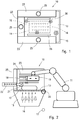
- the cleaning apparatus 10 comprises a table 13 for supporting a bag 12, in combination with a robot 11 for moving dirty bags to be cleaned from a pallet and for transferring the dirty bags to the support table 13.
- the support table 13 for the bag 12 to be cleaned can be configured in any manner provided it is suitable for enabling the bag 12 to be cleaned by a plurality of jets of a fluid directed upwards, through a plurality of passage openings of the support table 13; in this regard, the support table 13 can consist of a tough metal grid or can comprise a plurality of holes at a spraying zone for cleaning the bags 12, schematically indicated by reference 14 in figure 1 , or can consist of idle or driven rollers, or of a table of brushes configured for enabling a cleaning fluid to be sprayed.
- the device 11 for removing and transferring the bags 12 has been schematically represented in the form of a robot;
- the table 13 for supporting and for cleaning the bags 12 is supported by a hopper 15 for collecting the cleaning fluid and polluting substances that fall, dragged by the fluid, whereas they are removed by jets of fluid during a cleaning step for the bags.
- the cleaning fluid is a liquid
- the hopper 15, in addition to collecting the sludge, is also used to contain the excess liquid; if desired, in certain cases the hopper 15 for collecting the cleaning fluid and polluting substances can operate in a slight vacuum condition by connecting the hopper 15 to a suitable air sucking device.
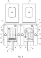
- a plurality of lower spray nozzles 16 oriented upwards are provided and connected to a suitable source 17 of a pressurised cleaning fluid of the type referred to previously; the pressurised jets of fluid that exit the nozzles 16, through the meshes of the grid or openings of the table 13, are directed upwards against the lower and the side surfaces of the bag 12, removing the dirt and the polluting substances, which are dragged by the fluid until they fall into the hopper underneath.
- the upper spray nozzles 18 are fixed to a side of a holding head 19 for removing the bags 12, the holding head 19 being fixed to the articulated arm of the robot 11.
- the holding head 19 can be of any type, for example a mechanical or pneumatic head that can be moved vertically and/or horizontally, as shown.
- the cleaning apparatus 10 can be optionally provided with one or more mechanical cleaning devices; in the case shown in figure 2 , a first mechanical cleaning device 20 schematically represented on the front side of the support table 13, consisting, for example, of a rotating brush, and a second mechanical cleaning device on the rear side of the table 13, for example consisting of a rotating brush 21 fixed to the stem of a linear actuator or pneumatic cylinder 22; thus the brush 21 can be moved longitudinally in contact with the bag 12.
- any other mechanical cleaning device can be used.
- the cleaning apparatus in addition to preventing contamination of the substance contained in the bag 12, also has to be able to prevent repollution of the bag or container 12 during the cleaning step, and to prevent the dispersal of polluting substances externally; thus, according to another feature of the cleaning apparatus 10, above the table 13 for supporting and cleaning the bags 12, air-sucking means are provided along the peripheral edges of the support table 13 for the bags.
- the air-sucking devices consist of sucking walls 23 that extend upwards on the two longitudinal sides and on the rear transverse side of the table 13, forming a protective barrier.
- the sucking walls 23 can consist of hollow walls, having on the internal side facing the cleaning zone 14 provided with sucking holes or slits 24, as shown in figure 2 ; the hollow walls 23, above or on an external side have a hole 25 for connection to a system of sucking conduits.
- FIG 1 with reference 26 two side bars are indicated for centring the bags 12 on the table 13, at the cleaning zone 14.
- robot 11 after removal of a dirty bag 12, deposits the dirty bag 12 on the cleaning zone 14 of the support table 13; during the insertion of the bag 12, the lower side thereof can be partially cleaned by the brush 20, if present.
- both the lower spray nozzles 16 and the upper spray nozzles 18 are activated, the latter moving by means of the articulated arm of the robot 11; obviously, the drive sequence of the lower and upper spray nozzles can also be different from the drive sequence referred to above. Whilst the cleaning fluid is being sprayed, the rotating brush 21 can be moved by the actuator 22.
- the washing fluid that is sprayed against the bag 12 at a certain pressure removes all the dirt and the polluting substances that have adhered over time, or have been deposited on the bag, which are dragged by the cleaning fluid so as to fall into the collecting hopper 15.
- the air sucking walls 23 are activated, preventing the dirt or polluting substances suspended in the air from being able to fall and again contaminate the bag 12, or the exterior.
- the disclosed cleaning apparatus permits a high degree of integration and automation to significantly reduce work times; this can be illustrated with reference to the examples of the remaining figures.
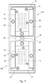
- FIG 3 a system has been shown comprising two cleaning stations 10A and 10B that are alongside one another, consisting of cleaning apparatuses similar to or completely identical to those of figures 1 and 2 ; thus also in figure 3 the same reference numbers have been used to indicate similar or equivalent parts.
- the robot 11 has not been shown that alternatively serves the two stations 10A and 10B, as explained before.
- the removing and/or deposition point for the bags 12A and 12B has been indicated.
- the operative method of the cleaning system of figure 3 is completely similar to that of the apparatus of figures 1 and 2 , with the only difference that now a single robot 11 is used to serve in sequence the two cleaning stations 10A and 10B, in this way enabling a higher automation degree and a consequent reduction of the work cycle.
- the system operates in the following manner: as mentioned previously, a single robot that is not shown, for moving and transferring the bags 12, removes a bag 12A from the removal point 30 and positions the bag 12A in the spraying zone 14 of the station 10A, where it is subjected to cleaning by spray jets of gas and/or liquid, and to a possible mechanical brushing action, depending on the type of bag and/or of the contents thereof; during the cleaning operation, the dirt or possible polluting substances become detached from the bag, most fall into the hopper 15 underneath, with the same cleaning fluid, and partially, if they are present in the air, they are sucked by the walls 23.
- the robot after taking and positioning a dirty bag 12A in the axially aligned cleaning station 10A, immediately afterwards removes a clean bag 12B from the station 10B, which in the meantime has completed the cleaning operations, and after depositing the bag, replaces the clean bag with a new bag to be cleaned.
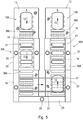
- FIG 4 shows a second solution, still relating to a double cleaning system, in which the two stations 10A and 10B are axially aligned and are integrated into a single structure 32 rotatably around a vertical axis 33 operationally connected to a rotary actuator 34; also in figure 4 the same reference numbers as the previous figures have been used to indicate similar or equivalent parts.
- the support structure 32 of the two cleaning stations 10A and 10B can rotate in a single direction or alternatively in the two opposite directions, providing in both cases a suitable rotating distributor connecting nozzles 16 to a source of pressurised cleaning fluid.
- a single robot for removing and transferring the bags which is not shown, can be provided as in the previous cases, further, both the cleaning stations 10A and 10B can be optionally provided with mechanical cleaning devices, for example of the roller type, as in the previous cases.
- the operation of the cleaning system of figure 4 is substantially similar to that of figure 3 , with the sole difference that now the dirty bags or containers are loaded, and the clean bags or containers are unloaded with the supporting structure 32 of the two cleaning stations 10A and 10B that is stationary and in a position aligned with the loading and unloading device, whereas the cleaning operation can be initiated and made to continue during rotation. Also in this case system productivity and versatility is increased, enabling in all cases the desired objects to be achieved.
- Figure 5 shows a further solution in which the single bags 12 are moved along a cleaning path in a tunnel type system, comprising a plurality of successive cleaning stations 10A, 10N, in each of which a determined cleaning, washing and/or sterilisation operation can be performed with a suitable gaseous and/or powder fluid, depending on the case.
- the cleaning system is served by a single robot for removing and transferring the bags, which is not shown, which loads the dirty bags at one end A of the cleaning line and unloads the clean bags at the other end B; again in figure 5 the same reference numbers have been used to indicate parts that are similar or equivalent to those of the preceding figures.
- the cleaning line extends along a U-shaped path, i.e.
- a path comprising a first linear portion 35A along which the bags 12 are advanced in one direction by a first conveyor 36A, for example of the roller type, and a second linear portion 35B, alongside and parallel to the previous one, along which the bags 12 are advanced in a direction opposite the previous one, for example by a second roller conveyor 36B; the rollers of the two conveyors 36A and 36B, in a manner that is per se known, are operationally connected to a driven reduction unit by a suitable chain or other type of transmission, which is not shown.
- the bags 12 can be transferred from the portion 35A to the portion 35B of the cleaning system in any manner, for example by a transverse conveyor 37 of the belt type, or in another manner.
- the air sucking walls 23 are provided peripherally on the external and internal sides of the two portions 35A and 35B of the cleaning line, as shown, again making use of the same reference numbers to indicate similar or equivalent parts.
- FIG 5 three cleaning stations 10 have been shown along each portion 35A and 35B providing spray nozzles 16 and hoppers for collecting the fluid and the pollutants independent for each axially aligned cleaning station, or common to several stations 10, depending on design requirements and needs.
- the dirty bags 12 are loaded singularly onto the front end A of the first portion of line 35A, and are then made to advance by the roller conveyor 36A, through the three cleaning stations 10 where they are washed and cleaned with a same or with different types of cleaning fluids, undergoing possible brushing in the intermediate axially aligned cleaning station by means of one or more rotating brushes 21.
- each portion 35A and 35B of the cleaning line comprise a greater or lesser number of stations 10 than those shown, providing a number and type of spray nozzles that are the same or different for each axially aligned cleaning station 10, depending on the different needs with regard to cleaning the bags or containers 12.
Landscapes
- Engineering & Computer Science (AREA)
- Mechanical Engineering (AREA)
- Cleaning In General (AREA)
Description
- The present invention refers to an apparatus and a cleaning system that are suitable for removing dirt or polluting substances that have adhered to the external surface of containers, in particular containers for loose substances, intended for automatic opening and emptying plants.
- For the purposes of the present description, the term "container" is defined as any type of bag, box, stiff or flexible package made of paper, cardboard, fabric, plastics or a combination thereof Further, the loose substance inside the containers can be of any type; for example, it can consist of powder, granular, liquid or pasty substances. Lastly, the containers can be cleaned by spraying any type of liquid, gas or powder fluid, for example, air, water, sterilising gas or liquids, disinfecting gas or liquids, fluidising powders in general, or combinations thereof, in function of the type of container, of the material with which the container has been made, and/or of the loose substance contained therein.
- The apparatus and the cleaning system according to the invention lend themselves to applied to any technological field, for example to the food, chemical, industrial sector, i.e. in all those cases in which the containers, before being automatically emptied, have to be washed or cleaned to ensure suitable conditions for avoiding that dirt or polluting substances that have adhered to the external surface of the containers during conveying and/or storing thereof, can become mixed, during automatic opening of the containers, with the substance contained therein, and contaminate said substance.
- As already mentioned, containers for loose substances, such as bags, boxes or the like, before being automatically opened and emptied, have to be suitably washed and/or cleaned to avoid dirt or extraneous substances, which have adhered to the external surface of the containers, during opening and emptying can pollute the substance or the product contained therein, or be dispersed towards the external environment.
- Currently, for cleaning containers, in general, a manual procedure is followed, using brushes, jets of pressurised water or air on each single container, before opening.
- Cleaning containers manually, in addition to requiring much time, does not ensure a thorough degree of hygiene and cleaning, and an appropriate protection of the external environment, negatively affecting the work cycle and the automatic opening systems.
- Using simple conveyors provided with spray nozzles, would not in itself solve the problem of automation avoiding recontamination of the containers and dispersal of contaminating substances in the external environment.
- Further, the tendency today to increase the productivity of automatic plants for opening containers requires automatic cleaning solutions and devices that are extremely versatile that are able to meet the most diverse needs.
-
US 2007/056612A1 discloses a tunnel washer, particularly for cleaning articles used in the care of laboratory animals, that includes fluid exhaust paths and spaced-apart double wall curtains for isolating chambers of the tunnel; the tunnel washer also includes an air manifold for uniformly drying the articles. -
DE 4332857A1 discloses a semiconductor cleaning apparatus which includes a cleaning portion for cleaning a wafer, a wafer cleaning portion for cleaning with water the cleaned wafer and a drying portion for drying the wafer cleaned with water. - One object of the present invention is thus to provide an apparatus that is suitable for the external cleaning of containers for loose substances, which requires a high degree of automation, minimising, if not wholly eliminating any risk of contamination of the environment and of the product during opening and emptying of the containers.
- A further object of the invention is to provide a system suitable for external cleaning of containers, that is extremely versatile and is able to permit a high degree of productivity.
- Another object of the invention is to provide a system for external cleaning of containers, as previously mentioned, which enables successive cleaning steps to be executed using the same cleaning fluid, or using different cleaning fluids, depending on the features of the containers to be cleaned and on the nature of the loose substance contained therein.
- The objects referred to above are achievable with an apparatus suitable for the external cleaning of containers for loose substances, according to claim 1, respectively with a system according to claim 7.
- The apparatus and the system for the external cleaning of containers, according to the present invention, will be explained in greater detail here below, with reference to the attached drawings, in which:
-
Fig. 1 shows schematically a plan view of the cleaning apparatus; -
Fig. 2 is a longitudinal section according to the line 2-2 offigure 1 , in combination with an automatic robot for removing and transferring the containers; -
Fig. 3 shows a dual cleaning system comprising two cleaning apparatuses that are alongside one another and functionally integrated; -
Fig. 4 shows a cleaning system of turnable type; -
Fig. 5 shows a multiple-station cleaning system of tunnel type which does not fall under the scope of the claims. - With reference to
figures 1 and 2 the general features of a cleaning apparatus according to the invention will now be disclosed, suitable for cleaning bags for containing loose products; nevertheless, what will be said here below with reference to the cleaning of bags in general must be understood to apply to the external cleaning of any type of container.
As shown, thecleaning apparatus 10 according to the example infigures 1 and 2 comprises a table 13 for supporting abag 12, in combination with arobot 11 for moving dirty bags to be cleaned from a pallet and for transferring the dirty bags to the support table 13.
The support table 13 for thebag 12 to be cleaned can be configured in any manner provided it is suitable for enabling thebag 12 to be cleaned by a plurality of jets of a fluid directed upwards, through a plurality of passage openings of the support table 13; in this regard, the support table 13 can consist of a tough metal grid or can comprise a plurality of holes at a spraying zone for cleaning thebags 12, schematically indicated byreference 14 infigure 1 , or can consist of idle or driven rollers, or of a table of brushes configured for enabling a cleaning fluid to be sprayed. - Still with reference to
figures 1 and 2 , thedevice 11 for removing and transferring thebags 12 has been schematically represented in the form of a robot; - The table 13 for supporting and for cleaning the
bags 12 is supported by ahopper 15 for collecting the cleaning fluid and polluting substances that fall, dragged by the fluid, whereas they are removed by jets of fluid during a cleaning step for the bags. If the cleaning fluid is a liquid, thehopper 15, in addition to collecting the sludge, is also used to contain the excess liquid; if desired, in certain cases thehopper 15 for collecting the cleaning fluid and polluting substances can operate in a slight vacuum condition by connecting thehopper 15 to a suitable air sucking device. - Inside the
hopper 15, at thespraying zone 14 and the table 13 supporting thebags 12, a plurality oflower spray nozzles 16 oriented upwards are provided and connected to asuitable source 17 of a pressurised cleaning fluid of the type referred to previously; the pressurised jets of fluid that exit thenozzles 16, through the meshes of the grid or openings of the table 13, are directed upwards against the lower and the side surfaces of thebag 12, removing the dirt and the polluting substances, which are dragged by the fluid until they fall into the hopper underneath.
In addition to thelower spray nozzles 16, it is possible to provide a plurality ofupper spray nozzles 18 oriented downwards, to clean the side of thebag 12 facing upwards. Theupper spray nozzles 18 are fixed to a side of aholding head 19 for removing thebags 12, theholding head 19 being fixed to the articulated arm of therobot 11. Theholding head 19 can be of any type, for example a mechanical or pneumatic head that can be moved vertically and/or horizontally, as shown. - In addition to fluid-jet cleaning of the
bags 12, thecleaning apparatus 10 can be optionally provided with one or more mechanical cleaning devices; in the case shown infigure 2 , a firstmechanical cleaning device 20 schematically represented on the front side of the support table 13, consisting, for example, of a rotating brush, and a second mechanical cleaning device on the rear side of the table 13, for example consisting of arotating brush 21 fixed to the stem of a linear actuator orpneumatic cylinder 22; thus thebrush 21 can be moved longitudinally in contact with thebag 12. Alternatively to or in combination with the mechanical cleaning devices shown, any other mechanical cleaning device can be used. - It has been specified that the cleaning apparatus according to the present invention, in addition to preventing contamination of the substance contained in the
bag 12, also has to be able to prevent repollution of the bag orcontainer 12 during the cleaning step, and to prevent the dispersal of polluting substances externally; thus, according to another feature of thecleaning apparatus 10, above the table 13 for supporting and cleaning thebags 12, air-sucking means are provided along the peripheral edges of the support table 13 for the bags. - In the case shown in
figures 1 and 2 , the air-sucking devices consist of suckingwalls 23 that extend upwards on the two longitudinal sides and on the rear transverse side of the table 13, forming a protective barrier. - For example, the sucking
walls 23 can consist of hollow walls, having on the internal side facing thecleaning zone 14 provided with sucking holes orslits 24, as shown infigure 2 ; thehollow walls 23, above or on an external side have ahole 25 for connection to a system of sucking conduits. Lastly, infigure 1 , withreference 26 two side bars are indicated for centring thebags 12 on the table 13, at thecleaning zone 14. - The operation of the cleaning apparatus disclosed is briefly as follows:
robot 11, after removal of adirty bag 12, deposits thedirty bag 12 on thecleaning zone 14 of the support table 13; during the insertion of thebag 12, the lower side thereof can be partially cleaned by thebrush 20, if present. - Once the
bag 12 has been deposited on the table 13 and released by theholding head 19 of therobot 11 at thecleaning zone 14, both thelower spray nozzles 16 and theupper spray nozzles 18 are activated, the latter moving by means of the articulated arm of therobot 11; obviously, the drive sequence of the lower and upper spray nozzles can also be different from the drive sequence referred to above. Whilst the cleaning fluid is being sprayed, the rotatingbrush 21 can be moved by theactuator 22. - Once
spray nozzles 16 and/or 18 have been activated, the washing fluid that is sprayed against thebag 12 at a certain pressure, removes all the dirt and the polluting substances that have adhered over time, or have been deposited on the bag, which are dragged by the cleaning fluid so as to fall into thecollecting hopper 15. During the spraying step of the cleaning fluid, theair sucking walls 23 are activated, preventing the dirt or polluting substances suspended in the air from being able to fall and again contaminate thebag 12, or the exterior. - When the operation of cleaning a
bag 12 has terminated therobot 11 is again driven to remove the clean bag and deposit the bag in a collecting point, from which it is moved to a subsequent opening and emptying step; at this point the operative cycle can be started again to clean anotherbag 12. - As mentioned before, the disclosed cleaning apparatus permits a high degree of integration and automation to significantly reduce work times; this can be illustrated with reference to the examples of the remaining figures.
- In
figure 3 a system has been shown comprising twocleaning stations figures 1 and 2 ; thus also infigure 3 the same reference numbers have been used to indicate similar or equivalent parts. For reasons of drawing simplicity, infigure 3 therobot 11 has not been shown that alternatively serves the twostations figure 3 with 30 and 31 the removing and/or deposition point for thebags - The operative method of the cleaning system of
figure 3 is completely similar to that of the apparatus offigures 1 and 2 , with the only difference that now asingle robot 11 is used to serve in sequence the twocleaning stations
In brief, the system operates in the following manner: as mentioned previously, a single robot that is not shown, for moving and transferring thebags 12, removes abag 12A from theremoval point 30 and positions thebag 12A in thespraying zone 14 of thestation 10A, where it is subjected to cleaning by spray jets of gas and/or liquid, and to a possible mechanical brushing action, depending on the type of bag and/or of the contents thereof; during the cleaning operation, the dirt or possible polluting substances become detached from the bag, most fall into thehopper 15 underneath, with the same cleaning fluid, and partially, if they are present in the air, they are sucked by thewalls 23. - The robot, after taking and positioning a
dirty bag 12A in the axially alignedcleaning station 10A, immediately afterwards removes aclean bag 12B from thestation 10B, which in the meantime has completed the cleaning operations, and after depositing the bag, replaces the clean bag with a new bag to be cleaned. - During the removing step and replacing a
clean bag 12B, the cleaning operation of thebag 12A in thestation 10A is completed; then the robot removes the clean bag from thestation 10A and replaces the clean bag with a new bag to be cleaned. The removing and cleaning operations of thebags stations
Thefigure 4 shows a second solution, still relating to a double cleaning system, in which the twostations single structure 32 rotatably around avertical axis 33 operationally connected to arotary actuator 34; also infigure 4 the same reference numbers as the previous figures have been used to indicate similar or equivalent parts. Thesupport structure 32 of the twocleaning stations distributor connecting nozzles 16 to a source of pressurised cleaning fluid. Also in this case, a single robot for removing and transferring the bags, which is not shown, can be provided as in the previous cases, further, both thecleaning stations
The operation of the cleaning system offigure 4 is substantially similar to that offigure 3 , with the sole difference that now the dirty bags or containers are loaded, and the clean bags or containers are unloaded with the supportingstructure 32 of the twocleaning stations
Figure 5 shows a further solution in which thesingle bags 12 are moved along a cleaning path in a tunnel type system, comprising a plurality ofsuccessive cleaning stations - Also in this latter case the cleaning system is served by a single robot for removing and transferring the bags, which is not shown, which loads the dirty bags at one end A of the cleaning line and unloads the clean bags at the other end B; again in
figure 5 the same reference numbers have been used to indicate parts that are similar or equivalent to those of the preceding figures.
In this respect, as shown infigure 5 , the cleaning line extends along a U-shaped path, i.e. a path comprising a firstlinear portion 35A along which thebags 12 are advanced in one direction by afirst conveyor 36A, for example of the roller type, and a second linear portion 35B, alongside and parallel to the previous one, along which thebags 12 are advanced in a direction opposite the previous one, for example by asecond roller conveyor 36B; the rollers of the twoconveyors - The
bags 12 can be transferred from theportion 35A to the portion 35B of the cleaning system in any manner, for example by atransverse conveyor 37 of the belt type, or in another manner. - Again, the
air sucking walls 23 are provided peripherally on the external and internal sides of the twoportions 35A and 35B of the cleaning line, as shown, again making use of the same reference numbers to indicate similar or equivalent parts. - In
figure 5 , three cleaningstations 10 have been shown along eachportion 35A and 35B providingspray nozzles 16 and hoppers for collecting the fluid and the pollutants independent for each axially aligned cleaning station, or common toseveral stations 10, depending on design requirements and needs. - The operation of the cleaning system of
figure 5 is briefly as follows: thedirty bags 12 are loaded singularly onto the front end A of the first portion ofline 35A, and are then made to advance by theroller conveyor 36A, through the three cleaningstations 10 where they are washed and cleaned with a same or with different types of cleaning fluids, undergoing possible brushing in the intermediate axially aligned cleaning station by means of one or more rotating brushes 21. - The
single bags 12, already partially cleaned, when they arrive at the rear end of the first portion ofline 35A, opposite the loading end, are transferred by thetransverse belt conveyor 37 to the rear end of the second cleaning line portion 35B along which they are made to advance by thesecond roller conveyor 36B, in a direction opposite the previous connection. Whilst thesingle bags 12 advance along the second portion of line 35B they undergo further cleaning treatments in the various sprayingstations 10, reaching thefinal unloading station 10N. - It is clear that, depending on the type of bag or
container 12, of the material with which the bag orcontainer 12 is made, on the type of substance, whether liquid, powder or in pasty state, contained in the single bags orcontainers 12, and on the type of dirt or pollutant to be cleaned, eachportion 35A and 35B of the cleaning line comprise a greater or lesser number ofstations 10 than those shown, providing a number and type of spray nozzles that are the same or different for each axially aligned cleaningstation 10, depending on the different needs with regard to cleaning the bags orcontainers 12. - What has been said and shown with reference to the examples of the enclosed figures has been provided by way of illustrative example of the technical features of the
cleaning apparatus 10, and of the entire system; accordingly other modifications or variations can be made to the cleaning apparatus offigure 1 or to the single cleaning stations of the entire system, without departing from the claims.
Claims (9)
- An apparatus (10) suitable for the external cleaning of containers (12) for loose substances, wherein the external surface of the containers (12) is contaminated by dirt and/or by polluting substances that have to be removed before opening the containers (12), comprising:a table (13) supporting the containers having at least one spraying zone (14) for a cleaning fluid configured with a plurality of passage openings of the fluid;a plurality of lower spray nozzles (16) of the cleaning fluid, underneath the spraying zone (14') of the support table (13) for the containers (12);a hopper (15) for collecting cleaning fluid, dirt and/or the pollutant removed from the containers (12); andprotective and air-sucking side walls (23), peripherally arranged on the support table (13) for the containers (12),upper spray nozzles (18) for a cleaning fluid, in position above the support table (13) for the containers (12),characterised in that the upper spray nozzles (18) are movably supported along the spraying zone (14) of the support table (13) for the containers (12), a robot (11) is provided for removing and transferring the containers (12), the upper spray nozzles (18) are fixed to a side of a holding head (19) for removing the containers (12), the holding head (19) being fixed to an articulated arm of the robot (11).
- The apparatus (10) suitable for the external cleaning of containers (12) according to claim 1, characterised by comprising at least one mechanical device (20, 21) for cleaning the containers (12).
- The apparatus (10) suitable for the external cleaning of containers (12) according to claim 2, characterised in that the mechanical cleaning device (21) is movable longitudinally to the support table (13) for the containers (12).
- The apparatus (10) suitable for the external cleaning of containers (12) according to any one of claims 1 to 3, characterised in that the protective walls (23) consist of hollow walls, a side of the protective walls (23) facing the spraying zone (14) being configured with a plurality of air-sucking openings (24).
- The apparatus (10) suitable for the external cleaning of containers according to any one of claims 1 to 4, characterised by comprising centring members (20) for centring the containers (12) at the spraying zone (14).
- The apparatus (10) suitable for the external cleaning of containers (12) according to claim 1, characterised in that the hopper (15) is operatively connected to an air sucking device.
- A system suitable for external cleaning of containers (12) for loose substances, wherein the external surface of the containers (12) is contamined by dirt and/or by polluting substances that have to be removed before opening the containers (12), comprising:first and second tables (13) supporting the containers having at least one spraying zone (14) for a cleaning fluid configured with a plurality of passage openings of the fluid;a plurality of lower spray nozzles (16) of the cleaning fluid, underneath the spraying zone (14') of each support table (13) for the containers (12);a hopper (15) for collecting cleaning fluid, dirt and/or the pollutant removed from the containers (12); andprotective and air-sucking side walls (23), peripherally arranged on each support table (13) for the containers (12),upper spray nozzles (18) for a cleaning fluid, in position above the support table (13) for the containers (12), characterised in that the upper spray nozzles (18) are movably supported along the spraying zone (14) of the support table (13) for the containers (12), whereina robot (11) is provided for removing and transferring the containers (12) to and from the tables (13), and wherein
the upper spray nozzles (18) are fixed to a side of a holding head (19) for removing the containers (12), the holding head (19) being fixed to an articulated arm of the robot (11). - The system suitable for external cleaning of containers according to claim 7, characterised by comprising a first and at least a second support table (13) parallely arranged alongside one another.
- The system suitable for external cleaning of containers (12) according to claim 7, characterised by comprising a first and a second axially aligned support table (13), wherein said support tables (13) are integrated into a rotating structure (32) according to a vertical axis (33).
Priority Applications (5)
| Application Number | Priority Date | Filing Date | Title |
|---|---|---|---|
| EP13175003.6A EP2821149B1 (en) | 2013-07-04 | 2013-07-04 | Apparatus and system for the external cleaning of containers for loose substances |
| NO13175003A NO2821149T3 (en) | 2013-07-04 | 2013-07-04 | |
| ES13175003.6T ES2667423T3 (en) | 2013-07-04 | 2013-07-04 | Apparatus and system for external cleaning of containers for loose substances |
| PL13175003T PL2821149T3 (en) | 2013-07-04 | 2013-07-04 | Apparatus and system for the external cleaning of containers for loose substances |
| DK13175003.6T DK2821149T3 (en) | 2013-07-04 | 2013-07-04 | APPLIANCE AND SYSTEM FOR EXTERNAL CLEANING OF LIQUID CONTAINERS |
Applications Claiming Priority (1)
| Application Number | Priority Date | Filing Date | Title |
|---|---|---|---|
| EP13175003.6A EP2821149B1 (en) | 2013-07-04 | 2013-07-04 | Apparatus and system for the external cleaning of containers for loose substances |
Publications (2)
| Publication Number | Publication Date |
|---|---|
| EP2821149A1 EP2821149A1 (en) | 2015-01-07 |
| EP2821149B1 true EP2821149B1 (en) | 2017-09-20 |
Family
ID=49118285
Family Applications (1)
| Application Number | Title | Priority Date | Filing Date |
|---|---|---|---|
| EP13175003.6A Active EP2821149B1 (en) | 2013-07-04 | 2013-07-04 | Apparatus and system for the external cleaning of containers for loose substances |
Country Status (5)
| Country | Link |
|---|---|
| EP (1) | EP2821149B1 (en) |
| DK (1) | DK2821149T3 (en) |
| ES (1) | ES2667423T3 (en) |
| NO (1) | NO2821149T3 (en) |
| PL (1) | PL2821149T3 (en) |
Families Citing this family (14)
| Publication number | Priority date | Publication date | Assignee | Title |
|---|---|---|---|---|
| CN104959335B (en) * | 2015-06-25 | 2017-08-22 | 国网山东省电力公司济南供电公司 | Transformer oil stain cleaning plant |
| CN105013730A (en) * | 2015-08-13 | 2015-11-04 | 吴江市元通纺织品有限公司 | Textile fiber cleaning device |
| CN105747995B (en) * | 2016-03-24 | 2018-06-12 | 福建省淼鑫投资管理有限公司 | A kind of automatic cleaning apparatus for rectangle dining table |
| CN106269620B (en) * | 2016-08-26 | 2018-08-28 | 国网山东省电力公司鄄城县供电公司 | Transformer oil stain cleaning plant |
| CN106423922B (en) * | 2016-09-28 | 2018-08-07 | 国网山东省电力公司章丘市供电公司 | Oil in transformer of electric substation mark cleaning plant |
| CN110447318B (en) * | 2017-03-22 | 2021-03-05 | 株式会社富士 | Tool management device |
| CN108745997A (en) * | 2018-07-26 | 2018-11-06 | 深圳市鑫万福珠宝首饰有限公司 | A kind of jewelry processing cleaning device |
| US11951610B2 (en) | 2018-07-31 | 2024-04-09 | Mjnn Llc | Opening apparatus for use with a multi-piece, hinged, hydroponic tower |
| CN109513649A (en) * | 2018-11-14 | 2019-03-26 | 俞海心 | A kind of rice harvesting machine inlet cleaning plant |
| CN109731819B (en) * | 2018-12-26 | 2021-07-23 | 中环艾能(高邮)能源科技有限公司 | Polycrystalline silicon wafer production device |
| US11723328B2 (en) * | 2019-05-08 | 2023-08-15 | Mjnn Llc | Cleaning apparatus for use with a plant support tower |
| CN110732518A (en) * | 2019-10-30 | 2020-01-31 | 湖南机电职业技术学院 | multifunctional toy cleaning machine |
| JP7255557B2 (en) * | 2020-06-12 | 2023-04-11 | 株式会社ダイフク | Conveyor equipment |
| CN113770140B (en) * | 2021-09-22 | 2023-04-14 | 哈尔滨华兴玻璃有限公司 | Glass bottle recycling and cleaning system |
Family Cites Families (8)
| Publication number | Priority date | Publication date | Assignee | Title |
|---|---|---|---|---|
| DE3014788A1 (en) * | 1980-04-17 | 1981-10-22 | Heinz Till | Cleaning appts. for barrel exteriors - has movable hooped pipe and nozzle unit rotating round correctly positioned stationary container |
| DE3715305A1 (en) * | 1987-05-08 | 1988-12-01 | Helmut Silberzahn | Washing system for the exterior cleaning of containers |
| DE9114761U1 (en) * | 1991-11-27 | 1992-04-02 | Gebr. Thiemt oHG, 4520 Melle | Extraction device for a powder coating system |
| JP3110218B2 (en) * | 1992-09-25 | 2000-11-20 | 三菱電機株式会社 | Semiconductor cleaning apparatus and method, wafer cassette, dedicated glove, and wafer receiving jig |
| FR2829714B1 (en) * | 2001-09-17 | 2004-09-10 | Italinnova Sas De Grandi Rene | METHOD AND INSTALLATION FOR CLEANING CONTAINERS |
| US7621285B2 (en) * | 2005-09-15 | 2009-11-24 | Steris Inc. | Tunnel washer system with improved cleaning efficiency |
| KR101253219B1 (en) * | 2011-05-12 | 2013-04-16 | (주)클레슨 | A large size box for automatic washing machine and automatic washing machine of washing method |
| FR2978685A1 (en) * | 2011-08-02 | 2013-02-08 | Ascodero Productique | Device for cleaning container for hydroponic culture for endives, has washing block including support structure, spraying units and separation units for separation of solid and liquid wastes, and processing unit for processing liquid waste |
-
2013
- 2013-07-04 NO NO13175003A patent/NO2821149T3/no unknown
- 2013-07-04 DK DK13175003.6T patent/DK2821149T3/en active
- 2013-07-04 EP EP13175003.6A patent/EP2821149B1/en active Active
- 2013-07-04 ES ES13175003.6T patent/ES2667423T3/en active Active
- 2013-07-04 PL PL13175003T patent/PL2821149T3/en unknown
Non-Patent Citations (1)
| Title |
|---|
| None * |
Also Published As
| Publication number | Publication date |
|---|---|
| PL2821149T3 (en) | 2018-04-30 |
| NO2821149T3 (en) | 2018-02-17 |
| ES2667423T3 (en) | 2018-05-10 |
| DK2821149T3 (en) | 2018-01-08 |
| EP2821149A1 (en) | 2015-01-07 |
Similar Documents
| Publication | Publication Date | Title |
|---|---|---|
| EP2821149B1 (en) | Apparatus and system for the external cleaning of containers for loose substances | |
| JP3298014B2 (en) | Industrial cleaning equipment | |
| EP2008728A1 (en) | Container-cleaning system | |
| US7143793B2 (en) | Cleaning system for a filling machine | |
| US20100218792A1 (en) | Packing Machine | |
| US7213606B2 (en) | Valve device, a unit for unloading loose materials from a dispenser device to a user unit comprising the valve device and a method for unloading loose material from a dispenser device to a user unit | |
| JP2011251828A (en) | Food conveying system | |
| JP2022519682A (en) | A chain cleaning module, a conveyor equipped with the chain cleaning module, and a method for cleaning the conveyor chain. | |
| JP5838504B2 (en) | Container cleaning system using robot | |
| CN211679185U (en) | Traditional Chinese medicine decocting barrel cleaning line | |
| JPH04215916A (en) | Method and device for carrying sausage | |
| JPH03242255A (en) | Method and device for coating workpiece | |
| JPS605530A (en) | Treating device for wafer surface | |
| JP2665474B2 (en) | External cleaning device for flexible containers | |
| KR101553014B1 (en) | Apparatus for washing and sterlization of agricultural and marine products | |
| JP2008110323A (en) | Apparatus and method for washing and drying container vessel | |
| CN116271154A (en) | High-temperature disinfection and sterilization equipment with automatic feeding function | |
| JP2009233596A (en) | Sterilization washing process and sterilization washing device | |
| CN212370686U (en) | Cleaning equipment | |
| CN111712330B (en) | Novel coating method and system | |
| EP0603975A1 (en) | A method and a device for cleaning containers | |
| JPH044082A (en) | Washing and drying device for moving container | |
| CN221086528U (en) | Spray cleaning equipment | |
| CN207872664U (en) | A kind of glue valve cleaning platform | |
| JPH0678632A (en) | Hydro-extractor in washing machine for raising seedling box |
Legal Events
| Date | Code | Title | Description |
|---|---|---|---|
| PUAI | Public reference made under article 153(3) epc to a published international application that has entered the european phase |
Free format text: ORIGINAL CODE: 0009012 |
|
| 17P | Request for examination filed |
Effective date: 20130704 |
|
| AK | Designated contracting states |
Kind code of ref document: A1 Designated state(s): AL AT BE BG CH CY CZ DE DK EE ES FI FR GB GR HR HU IE IS IT LI LT LU LV MC MK MT NL NO PL PT RO RS SE SI SK SM TR |
|
| AX | Request for extension of the european patent |
Extension state: BA ME |
|
| RBV | Designated contracting states (corrected) |
Designated state(s): AL AT BE BG CH CY CZ DE DK EE ES FI FR GB GR HR HU IE IS IT LI LT LU LV MC MK MT NL NO PL PT RO RS SE SI SK SM TR |
|
| R17P | Request for examination filed (corrected) |
Effective date: 20150630 |
|
| 17Q | First examination report despatched |
Effective date: 20151210 |
|
| GRAP | Despatch of communication of intention to grant a patent |
Free format text: ORIGINAL CODE: EPIDOSNIGR1 |
|
| STAA | Information on the status of an ep patent application or granted ep patent |
Free format text: STATUS: GRANT OF PATENT IS INTENDED |
|
| INTG | Intention to grant announced |
Effective date: 20170419 |
|
| GRAS | Grant fee paid |
Free format text: ORIGINAL CODE: EPIDOSNIGR3 |
|
| GRAA | (expected) grant |
Free format text: ORIGINAL CODE: 0009210 |
|
| STAA | Information on the status of an ep patent application or granted ep patent |
Free format text: STATUS: THE PATENT HAS BEEN GRANTED |
|
| AK | Designated contracting states |
Kind code of ref document: B1 Designated state(s): AL AT BE BG CH CY CZ DE DK EE ES FI FR GB GR HR HU IE IS IT LI LT LU LV MC MK MT NL NO PL PT RO RS SE SI SK SM TR |
|
| REG | Reference to a national code |
Ref country code: GB Ref legal event code: FG4D |
|
| REG | Reference to a national code |
Ref country code: CH Ref legal event code: EP |
|
| REG | Reference to a national code |
Ref country code: AT Ref legal event code: REF Ref document number: 929738 Country of ref document: AT Kind code of ref document: T Effective date: 20171015 |
|
| REG | Reference to a national code |
Ref country code: IE Ref legal event code: FG4D |
|
| REG | Reference to a national code |
Ref country code: DE Ref legal event code: R096 Ref document number: 602013026787 Country of ref document: DE |
|
| REG | Reference to a national code |
Ref country code: NL Ref legal event code: FP |
|
| REG | Reference to a national code |
Ref country code: DK Ref legal event code: T3 Effective date: 20180103 |
|
| REG | Reference to a national code |
Ref country code: SE Ref legal event code: TRGR |
|
| PG25 | Lapsed in a contracting state [announced via postgrant information from national office to epo] |
Ref country code: LT Free format text: LAPSE BECAUSE OF FAILURE TO SUBMIT A TRANSLATION OF THE DESCRIPTION OR TO PAY THE FEE WITHIN THE PRESCRIBED TIME-LIMIT Effective date: 20170920 Ref country code: HR Free format text: LAPSE BECAUSE OF FAILURE TO SUBMIT A TRANSLATION OF THE DESCRIPTION OR TO PAY THE FEE WITHIN THE PRESCRIBED TIME-LIMIT Effective date: 20170920 Ref country code: FI Free format text: LAPSE BECAUSE OF FAILURE TO SUBMIT A TRANSLATION OF THE DESCRIPTION OR TO PAY THE FEE WITHIN THE PRESCRIBED TIME-LIMIT Effective date: 20170920 |
|
| REG | Reference to a national code |
Ref country code: LT Ref legal event code: MG4D |
|
| REG | Reference to a national code |
Ref country code: AT Ref legal event code: MK05 Ref document number: 929738 Country of ref document: AT Kind code of ref document: T Effective date: 20170920 |
|
| REG | Reference to a national code |
Ref country code: NO Ref legal event code: T2 Effective date: 20170920 |
|
| PG25 | Lapsed in a contracting state [announced via postgrant information from national office to epo] |
Ref country code: BG Free format text: LAPSE BECAUSE OF FAILURE TO SUBMIT A TRANSLATION OF THE DESCRIPTION OR TO PAY THE FEE WITHIN THE PRESCRIBED TIME-LIMIT Effective date: 20171220 Ref country code: LV Free format text: LAPSE BECAUSE OF FAILURE TO SUBMIT A TRANSLATION OF THE DESCRIPTION OR TO PAY THE FEE WITHIN THE PRESCRIBED TIME-LIMIT Effective date: 20170920 Ref country code: GR Free format text: LAPSE BECAUSE OF FAILURE TO SUBMIT A TRANSLATION OF THE DESCRIPTION OR TO PAY THE FEE WITHIN THE PRESCRIBED TIME-LIMIT Effective date: 20171221 Ref country code: RS Free format text: LAPSE BECAUSE OF FAILURE TO SUBMIT A TRANSLATION OF THE DESCRIPTION OR TO PAY THE FEE WITHIN THE PRESCRIBED TIME-LIMIT Effective date: 20170920 |
|
| PG25 | Lapsed in a contracting state [announced via postgrant information from national office to epo] |
Ref country code: CZ Free format text: LAPSE BECAUSE OF FAILURE TO SUBMIT A TRANSLATION OF THE DESCRIPTION OR TO PAY THE FEE WITHIN THE PRESCRIBED TIME-LIMIT Effective date: 20170920 Ref country code: RO Free format text: LAPSE BECAUSE OF FAILURE TO SUBMIT A TRANSLATION OF THE DESCRIPTION OR TO PAY THE FEE WITHIN THE PRESCRIBED TIME-LIMIT Effective date: 20170920 |
|
| REG | Reference to a national code |
Ref country code: ES Ref legal event code: FG2A Ref document number: 2667423 Country of ref document: ES Kind code of ref document: T3 Effective date: 20180510 |
|
| PG25 | Lapsed in a contracting state [announced via postgrant information from national office to epo] |
Ref country code: SM Free format text: LAPSE BECAUSE OF FAILURE TO SUBMIT A TRANSLATION OF THE DESCRIPTION OR TO PAY THE FEE WITHIN THE PRESCRIBED TIME-LIMIT Effective date: 20170920 Ref country code: SK Free format text: LAPSE BECAUSE OF FAILURE TO SUBMIT A TRANSLATION OF THE DESCRIPTION OR TO PAY THE FEE WITHIN THE PRESCRIBED TIME-LIMIT Effective date: 20170920 Ref country code: AT Free format text: LAPSE BECAUSE OF FAILURE TO SUBMIT A TRANSLATION OF THE DESCRIPTION OR TO PAY THE FEE WITHIN THE PRESCRIBED TIME-LIMIT Effective date: 20170920 Ref country code: IS Free format text: LAPSE BECAUSE OF FAILURE TO SUBMIT A TRANSLATION OF THE DESCRIPTION OR TO PAY THE FEE WITHIN THE PRESCRIBED TIME-LIMIT Effective date: 20180120 Ref country code: EE Free format text: LAPSE BECAUSE OF FAILURE TO SUBMIT A TRANSLATION OF THE DESCRIPTION OR TO PAY THE FEE WITHIN THE PRESCRIBED TIME-LIMIT Effective date: 20170920 |
|
| REG | Reference to a national code |
Ref country code: DE Ref legal event code: R097 Ref document number: 602013026787 Country of ref document: DE |
|
| REG | Reference to a national code |
Ref country code: FR Ref legal event code: PLFP Year of fee payment: 6 |
|
| PLBE | No opposition filed within time limit |
Free format text: ORIGINAL CODE: 0009261 |
|
| STAA | Information on the status of an ep patent application or granted ep patent |
Free format text: STATUS: NO OPPOSITION FILED WITHIN TIME LIMIT |
|
| 26N | No opposition filed |
Effective date: 20180621 |
|
| PG25 | Lapsed in a contracting state [announced via postgrant information from national office to epo] |
Ref country code: SI Free format text: LAPSE BECAUSE OF FAILURE TO SUBMIT A TRANSLATION OF THE DESCRIPTION OR TO PAY THE FEE WITHIN THE PRESCRIBED TIME-LIMIT Effective date: 20170920 |
|
| PG25 | Lapsed in a contracting state [announced via postgrant information from national office to epo] |
Ref country code: LU Free format text: LAPSE BECAUSE OF NON-PAYMENT OF DUE FEES Effective date: 20180704 Ref country code: MC Free format text: LAPSE BECAUSE OF FAILURE TO SUBMIT A TRANSLATION OF THE DESCRIPTION OR TO PAY THE FEE WITHIN THE PRESCRIBED TIME-LIMIT Effective date: 20170920 |
|
| REG | Reference to a national code |
Ref country code: IE Ref legal event code: MM4A |
|
| PG25 | Lapsed in a contracting state [announced via postgrant information from national office to epo] |
Ref country code: IE Free format text: LAPSE BECAUSE OF NON-PAYMENT OF DUE FEES Effective date: 20180704 |
|
| PG25 | Lapsed in a contracting state [announced via postgrant information from national office to epo] |
Ref country code: MT Free format text: LAPSE BECAUSE OF NON-PAYMENT OF DUE FEES Effective date: 20180704 |
|
| PG25 | Lapsed in a contracting state [announced via postgrant information from national office to epo] |
Ref country code: TR Free format text: LAPSE BECAUSE OF FAILURE TO SUBMIT A TRANSLATION OF THE DESCRIPTION OR TO PAY THE FEE WITHIN THE PRESCRIBED TIME-LIMIT Effective date: 20170920 |
|
| PG25 | Lapsed in a contracting state [announced via postgrant information from national office to epo] |
Ref country code: PT Free format text: LAPSE BECAUSE OF FAILURE TO SUBMIT A TRANSLATION OF THE DESCRIPTION OR TO PAY THE FEE WITHIN THE PRESCRIBED TIME-LIMIT Effective date: 20170920 Ref country code: HU Free format text: LAPSE BECAUSE OF FAILURE TO SUBMIT A TRANSLATION OF THE DESCRIPTION OR TO PAY THE FEE WITHIN THE PRESCRIBED TIME-LIMIT; INVALID AB INITIO Effective date: 20130704 |
|
| PG25 | Lapsed in a contracting state [announced via postgrant information from national office to epo] |
Ref country code: MK Free format text: LAPSE BECAUSE OF NON-PAYMENT OF DUE FEES Effective date: 20170920 Ref country code: CY Free format text: LAPSE BECAUSE OF FAILURE TO SUBMIT A TRANSLATION OF THE DESCRIPTION OR TO PAY THE FEE WITHIN THE PRESCRIBED TIME-LIMIT Effective date: 20170920 |
|
| PG25 | Lapsed in a contracting state [announced via postgrant information from national office to epo] |
Ref country code: AL Free format text: LAPSE BECAUSE OF FAILURE TO SUBMIT A TRANSLATION OF THE DESCRIPTION OR TO PAY THE FEE WITHIN THE PRESCRIBED TIME-LIMIT Effective date: 20170920 |
|
| PGFP | Annual fee paid to national office [announced via postgrant information from national office to epo] |
Ref country code: NO Payment date: 20230727 Year of fee payment: 11 Ref country code: IT Payment date: 20230726 Year of fee payment: 11 Ref country code: GB Payment date: 20230727 Year of fee payment: 11 Ref country code: ES Payment date: 20230804 Year of fee payment: 11 Ref country code: CH Payment date: 20230802 Year of fee payment: 11 |
|
| REG | Reference to a national code |
Ref country code: DE Ref legal event code: R079 Ref document number: 602013026787 Country of ref document: DE Free format text: PREVIOUS MAIN CLASS: B08B0001040000 Ipc: B08B0001320000 |
|
| PGFP | Annual fee paid to national office [announced via postgrant information from national office to epo] |
Ref country code: SE Payment date: 20230727 Year of fee payment: 11 Ref country code: FR Payment date: 20230725 Year of fee payment: 11 Ref country code: DK Payment date: 20230727 Year of fee payment: 11 Ref country code: DE Payment date: 20230727 Year of fee payment: 11 Ref country code: BE Payment date: 20230727 Year of fee payment: 11 |
|
| PGFP | Annual fee paid to national office [announced via postgrant information from national office to epo] |
Ref country code: PL Payment date: 20240620 Year of fee payment: 12 |
|
| PGFP | Annual fee paid to national office [announced via postgrant information from national office to epo] |
Ref country code: NL Payment date: 20240726 Year of fee payment: 12 |